

Page 1

Grindmaster Model FDD2500
Service Manual
for
Model FDD2500
Warning Labels.................................... 12
Installation .......................................... 13
Programming ...................................... 14
Start-up & Adjustments ...................... 17
Cleaning .............................................. 18
Shipping Preparation........................ 110
Replacing Controller ............................11
Replacing Components ........................11
Product Out Adjustment......................11
Troubleshooting Guide ........................12
Assembly Drawings ..............................14
Wiring Diagrams.................................. 28
Table of Contents
Prior authorization must be obtained from Grindmaster
Corporation for all warranty claims.
© Grindmaster Corporation, 2005 0905 Form # AM-342-02
PRINTED IN USA Part #63361
Grindmaster Corporation
4003 Collins Lane
Louisville, KY 40245 USA
(502) 425-4776
(800) 695-4500 (USA & Canada only)
FAX: (502) 425-4664
www.grindmaster.com
Model FDD2500-1-M-B
Model FDD2500-3-M-B
Model FDD2500-1-3A-B
Model FDD2500-3-3A-B
Page 2
Page 2 Model FDD2500
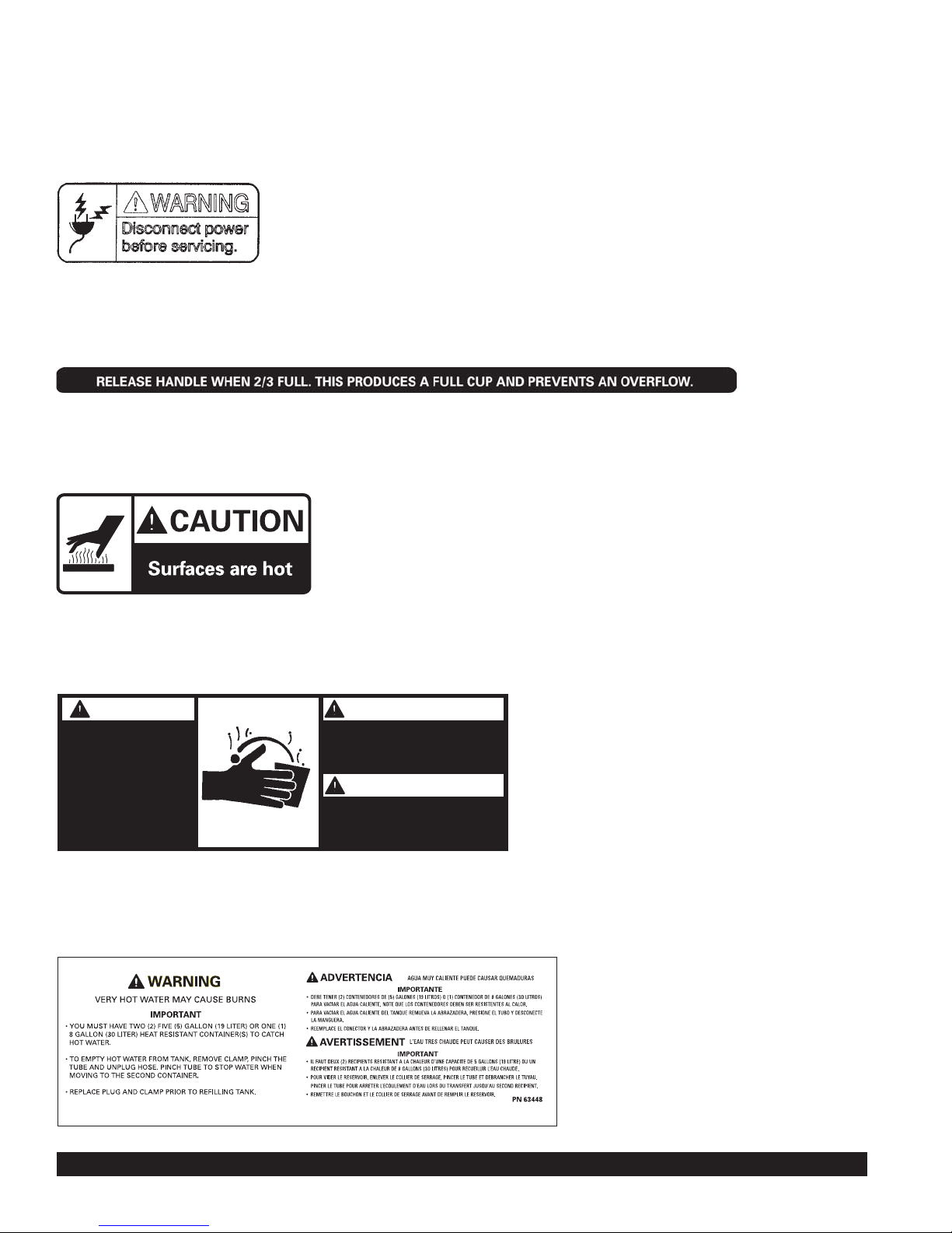
Warning Labels
The following warning labels were on your dispenser when it was shipped from the factory. They should remain on your dispenser
in good, readable condition at all times. If one of your labels is missing or damaged, order a replacement label immediately.
Part #71582
Located on machine cover and spout mounting bracket.
Part #63370
For FDD2500- -M-B models only
Located on front splash panel
Part #63371
Located next to center spout
Part #62981
Located on front splash panel
Part #63448
Located on tank drain hose
ADVERTENCIA
Contenidos pueden causar
quemadur as severas si el
uso es inadecuado .
AVERTISSEMENT
Contenu peut pr ovoquer
des brûlures grâves si il est
manipul é incorrectement.
WARNING
Contents can cause
severe burns if
handled impr oper ly.
PN# 62981
*
Page 3

Model FDD2500 Page 3
Installation
WATER INLET CONNECTION
The National Sanitation Foundation requires the following for an NSF approved water hook-up:
1. A quick disconnect water connection or enough coiled tubing so that the machine can be moved for cleaning
underneath.
2. An approved backflow prevention device, such as a double check valve to be installed between the machine and
water supply. On units plumbed to permanent water line, installation of a water filter/softener system is recommended
to prevent lime and scale build up in the machine. On units pumping from remote water container, filtered water
is recommended to prevent lime and scale buildup in the machine.
3. Water pipe connections and fixtures directly connected to potable water supply shall be sized, installed and maintained
in accordance with Federal, State, and Local codes.
WATER HOOK-UP
1. Install the 4" legs and hand tighten. Install the plastic drain tray onto the
drain tray bracket and install drain grid. (Note: The drain tray is provided with
a drill-out port to allow for plumbing to a drain.)
2. Remove front splash panel for access to water hook-up. (see Figure 1)
3. Ensure the 3/8" water supply hose has sufficient length to allow the machine
to be moved for cleaning or service. Supplying hot water to the machine will
greatly increase the capacity of the machine. The use of copper tubing is
required to prevent rupture when using a hot water supply. A maximum inlet
water temperature of 160°F (71°C) is recommended.
4. Flush the water line to purge any debris from the supply line.
5. Connect a 3/8" water line to the 3/8" male flare connection.
6. Ensure water supply to machine is within 20 to 100psi. Install a pressure
regulator if pressure is too high.
7. Turn on water supply and check for leaks.
WARNING: ELECTRIC SHOCK HAZARD
Only qualified service personnel should perform installation of this appliance.
Improper installation could result in serious injury or death.
WARNING: ELECTRIC SHOCK HAZARD
Always disconnect power to the machine before servicing or cleaning. Risk
of electric shock is present which can cause serious injury or death.
WARNING: ELECTRIC SHOCK HAZARD
Never use the ground conductor as a neutral conductor. Serious injury or
death could occur in the event of a fault condition.
Figure 1
Page 4
Page 4 Model FDD2500
Installation (cont.)
ELECTRICAL HOOK-UP
Ensure water connection is made to machine before proceeding.
The electrical ratings for your dispenser are located on the serial plate on the outside cabinet and inside door.
For configuration of three heater models to optional wattages, refer to page 31 of service manual.
1. For cord connected models, plug the power cord into an appropriate grounded
and dedicated electrical outlet. Go to step 8.
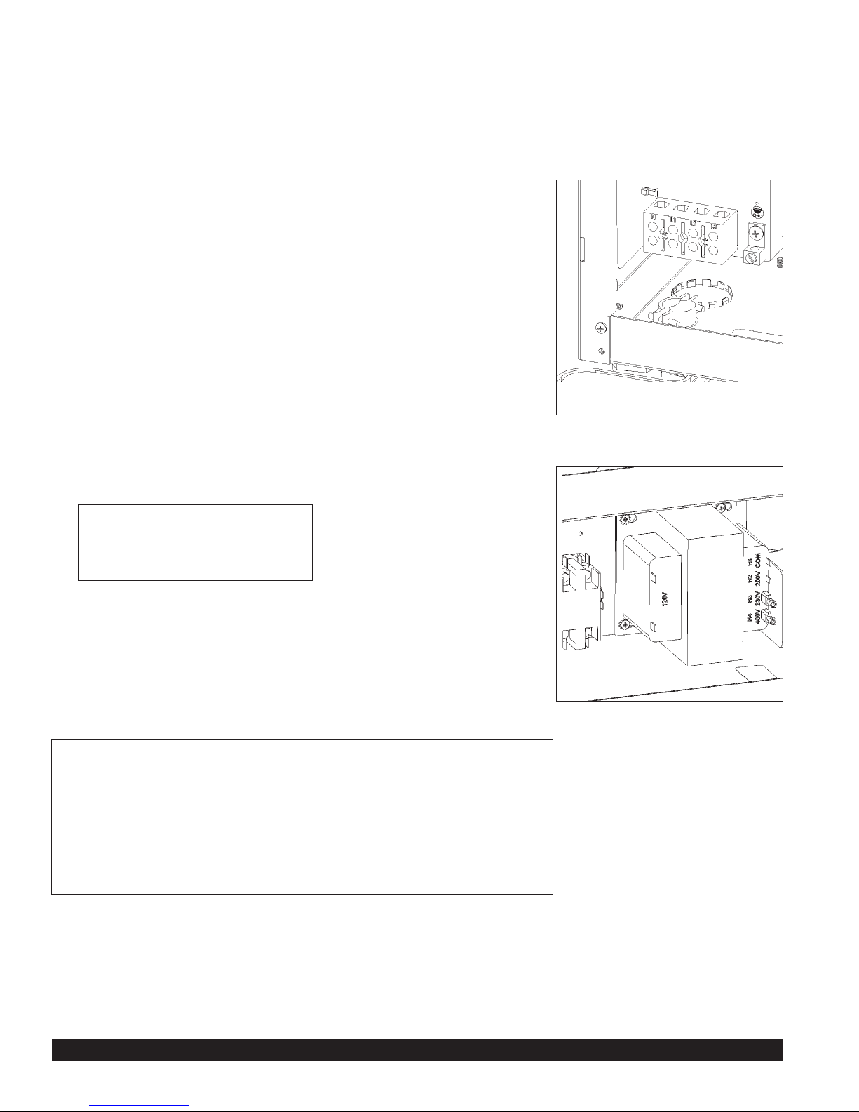
2. For hard-wired models not supplied with an electrical cord, the dispenser
should be connected to a dedicated circuit with a fused disconnect switch or
a circuit breaker near the dispenser.
3. Strain relief is supplied under the machine chassis for power entry.
(see Figure 2)
• Electrical connections and wiring materials must conform to local
codes and/or be in compliance with the National Electric Code
• Use only copper conductors
4. Note: Wiring diagram is on inside of left side panel.
5. Connect the power supply conductors, neutral (optional) and ground wire to
the appropriate positions on the terminal block. The ground lug is separate
from the terminal block. Note: machine is equipped with a stepdown
transformer to provide the necessary 120 volt power supply for the control
circuits. Neutral will not be used.
6. Remove lid and left side panel. (see Figure 3)
7. Install the front splash panel.
8. Install the plastic drain tray into the drain tray rails then place drain grid onto
drain tray.
9. Flip power supply to machine “ON” at the branch supply disconnect.
10. Flip power switch to the “ON” position and allow the water tank to fill. The
machine will make a subtle hissing sound while filling. Allow 3-4 minutes for
fill time depending on water pressure.
Attention: This machine employs an interlock switch to disable
the dispense and fill circuits when the front door is open. Ensure
the front door is closed while installing or operating the machine.
A watchdog circuit also monitors the water level in the tank and
will disable the machine if the water level in the tank is not normal
within (5) minutes of fill time. The machine will require power to
be reset to clear the watchdog timeout.
11. After the water tank has completed the fill cycle, the display will read “Water Heating” signifying that the heating
element has been activated. Allow 10-45 minutes for the display to read “Ready” signifying the water tank has
reached operating temperature. (Note: Heatup time is dependent on water inlet temperature and input wattage
to the machine.)
Figure 2
Figure 3
Move red wire on transformer to:
• “H2” for 208V supply
• “H3” for 240V supply
Page 5

Model FDD2500 Page 5
Programming Machine from Touchpads
Tools Required: None
MACHINE PROGRAMMING: The machine operating parameters can be changed from the touchpad and LCD display
without opening up the machine. (See illustration below).
To enter Programming Mode:
Press and hold (>) and (+) at the same time for approximately 5 seconds.
Tip: Use the eraser end of two pencils to press the buttons if you are having difficulty entering programming mode.
To Exit programming mode at anytime:
• Wait 20 seconds without pressing a button.
• The display will prompt “Exit?”
• Press (+) or (-) to toggle between YES and NO.
• After selecting YES, you MUST press (>) to SAVE changes, or wait for ready message and machine
will exit without saving.
Tip: To verify changes successfully save, re-enter programming mode and check settings.
1) Press (>) to select Language. (1A)
Press (+) to choose English, Spanish, German, or French.
2) Press (>) to set the Time of day on the machine.
Press (+) or (-) to change the time.
3) If password is activated, enter password now.
a) Press (+) to enter first number.
b) Press (>), then (+) to enter second number.
c) Press (>), then (+) to enter third number.
NOTE: The default password is “111”. If the password has been changed and forgotten, press “I/O” and “+” at the
same time to proceed.
4) Press (>) to change Password settings. (2B)
Press (+) or (-) to toggle between ON (enable password) and OFF (disable password).
If ON is selected, press (>) to change password.
a) Press (>) to enter new password. (following steps 3 a, b, c)
b) Press (>) to confirm new password. (following steps 3 a, b, c)
5) Press (>) to program Dispense Settings. (to change Portion Sizes) (2E) (For FDD2500-**-3A models only)
a) Press (+) for message “Select Dispense Button”. (5A)
b) Press the dispense button for the dispense head you wish to adjust the settings. LCD will display L, M,
or R for left, middle, or right dispense head to acknowledge your selection.
c) Once the dispense head is selected, press (+) or (-) to change the amount of time (portion size) for the
beverage being dispensed.
6) Press (>) to change Whipper Settings. (5A1)
a) Press the dispense button for the dispense head you wish to adjust the settings. LCD will display L, M,
or R for left, middle, or right dispense head to acknowledge your selection.
b) Once the dispense head is selected, press (+) or (-) to toggle between ON (turn whipper ON) and OFF
(turn whipper OFF).
7) Press (>) to return to Dispense Settings. (2E)
Repeat steps 6 & 7 for remaining heads.
8) Press (>) to modify Drink Strength. (7A)
a) Press (>) to Select a Dispense Button. (7B)
b) Press the dispense button for the dispense head that you want to change the drink strength for.
c) Press (+) or (-) to modify the auger speed which changes the drink strength (0-100% of maximum auger
speed in 1% increments).
Note: A faster speed will result in a stronger drink and a slower speed will result in a weaker drink.
PROCEED
POWER ON/OFF
(STANDBY)
INCREMENT UP
INCREMENT DOWN
Page 6

Page 6 Model FDD2500
Programming Machine from Touchpads (cont.)
9) Press (>) to modify Auger Delay.
a) Press (>) and select dispense button.
b) Press the dispense button for the dispense head that you want to change the auger ON delay time.
c) Press (+) or (-) to modify the time in tenths of a second.
10) Press (>) to modify Auger Off Delay.
a) Press the dispense button for the dispense head that you want to change the auger OFF delay time.
b) Press (+) or (-) to modify the time in tenths of a second.
11) Press (>) to change Heater settings. (8A)
Press (+) or (-) to toggle between ON (water tank heater ON) and OFF (water tank heater OFF).
12) Press (>) to modify Water Tank Temperature. (7A)
Press (+) or (-) to increase or decrease water tank temperature.
13) Press (>) to modify Low Temp/No Brew settings. (7B)
Press (+) or (-) to toggle between ON (will not allow drinks to dispense if water temperature is below
programmed temperature) and OFF.
a) If turned ON press (>) to modify Minimum Dispensing Temp.
b) Press (+) or (-) to increase or decrease Minimum Dispensing Temp.
14) Press (>) to change Sleep Mode settings. (8A)
Press (+) or (-) to toggle between OFF and ON (forces the water tank temperature to a programmed temperature
after a programmed time of inactivity – used for energy savings).
a) If turned ON, press (>) to change Sleep Mode Settings.
b) Press (+) or (-) to increase or decrease the amount of time the unit is inactive before going into sleep mode.
c) Press (>) to change sleep mode water tank temperature setting.
d) Press (+) or (-) to increase or decrease the water tank temperature during sleep mode.
15) Press (>) to view Manual Dispense mode. (9A)
(Models with manual Free-Flow Tomlinson handles cannot be changed to portion control.)
16) Press (>) for Sales Mode. (14A) (This option for future use. “Free” is currently the default setting.)
17) Press (>) to retrieve Sales Data. (15A)
18) Press (>) to view Total Dispense data (number of drinks dispensed per head). (15B)
Press the dispense buttons that you want to retrieve information about.
After viewing each head’s data, proceed to next step.
19) Press (>) to view Total Brews data. (15E)
LCD will display total number of drinks dispensed by the unit.
20) Press (>) for Clear Data options. (16A)
Press (+) or (-) to toggle between YES (resets sales data counter to “0”) and NO.
Important: After selecting YES and then pressing (>) all data will be cleared immediately.
21) Press (>) to view Dispenser Type. (17A)
LCD will display type of dispenser.
22) Press (>) to display Date Code information. (18A)
LCD will display manufacture date.
23) Press (>) to display Software Version on controller. (19A)
Displays current software version stored in controller memory.
24) Press (>) to Retrieve Error Codes. (20A)
Press (+) or (-) to toggle through and review all error codes. The LCD will display the number of times each
error code has occurred. Error Codes:
SC1: No Water Pressure
SC2: Reset Power (Error has occurred that requires power to be reset).
SC3: Low Water Level (Inlet valve ON for more than 5 minutes.)
Page 7
Model FDD2500 Page 7
Programming Machine from Touchpads (cont.)
24) Press (>) to Retrieve Error Codes. (20A) (cont.)
SC4: Thermistor Failure (Temperature is out of range – less than 32°F or greater than 210°F.)
SC6: Check Heating (Tank is too hot.)
SC8: Overcooling
SC9: Overflow (Water level safety probe is tripped.)
SC10: Adjust Temperature (Temperature adjusted from touchpad.)
25) Press (>) for Clear Error Code options. (20B)
Press (+) or (-) to toggle between YES (clears all stored error codes from memory) and NO.
Important: After selecting YES and then pressing (>) all data will be cleared immediately.
26) Press (>) for EXIT option
Press (+) or (-) to toggle between YES and NO.
Important: After selecting YES, you MUST press (>) to SAVE changes, or wait for READY message and machine
will exit without saving.
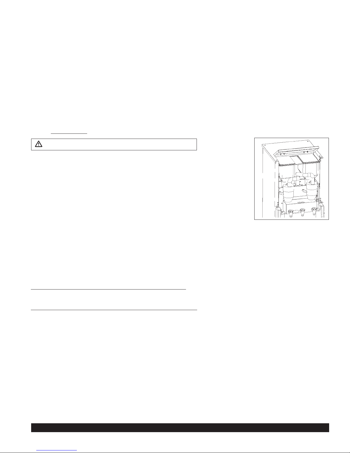
FILLING PRODUCT HOPPERS (see Figure 4)
1) Open door.
2) Lift hinged top.
3) Remove hopper lid.
4) Carefully pour product into hopper.
5) Replace hopper lid.
6) Lower hinged top.
7) Close door.
THERMOSTAT ADJUSTMENT
(See machine programming procedure: Water tank temperature)
Tools required: None
NOTE: The thermostat range is approximately 40°F to 205°F (4°C to 96°C). The water tank temperature is factory set
at 190°F (87°C), making the beverage temperature slightly lower than 190°F (87°C).
HOW TO DISPENSE A DRINK
Machine is equipped to dispense into cups, decanters, 1.3 L servers, 2.2 L airpots or hose connected to 5 gal. containers.
WARNING: Server must rest flat on tray with a 1/4" (6 mm) clearance between cup and spout. Contents can cause
severe burns if handled improperly.
For Manual Machines FDD2500-1-M-B and FDD2500-3-M-B:
1) Place a server under the selected drink dispense nozzle.
2) Pull dispense handle until cup is 2/3 full, then release handle.
For Automatic Machines FDD2500-1-3A-B and FDD2500-3-3A-B:
1) Place a server under the selected drink dispense nozzle.
2) Press and release desired dispense button.
NOTE: To stop a dispense, simply press-and-release any button.
Figure 4
WARNING: Disconnect power before servicing machine.
Page 8
Page 8 Model FDD2500
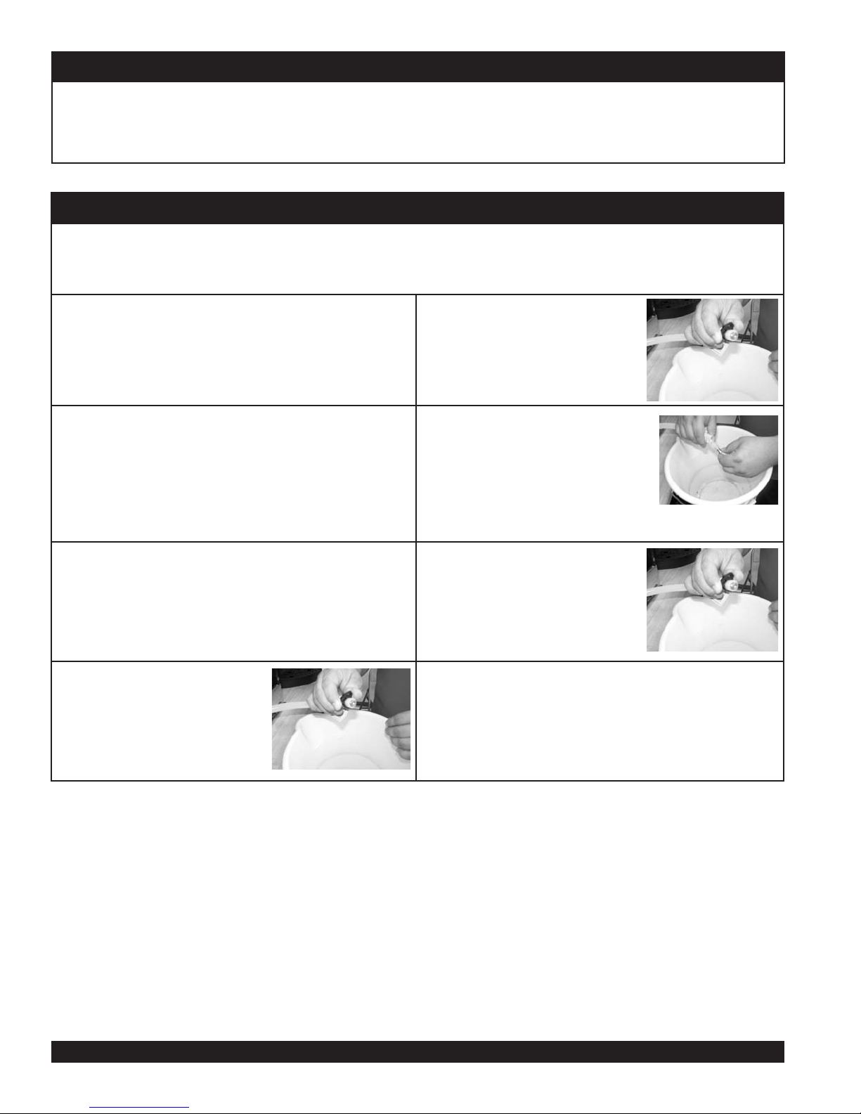
Weekly Cleaning
ylbmessaeR– lennuF eht gninaelCylbmessasiD – lennuF eht gninaelC
1.
Open the door and remove the large tube
from the funnel cover, then remove the
cover.
1.
Place funnel into position, then
connect hoses.
2.
Remove the mixing funnel by removing silicone tube at the side, then remove funnel.
2.
Place funnel cover on funnel and connect
large tube.
3.
PARTS IN CONTACT WITH FOOD MUST BE WASHED,
RINSED, SANITIZED, AND AIR DRIED.
Daily Cleaning
1.
CAUTION: When cleaning the unit, do not use cleansers, liquid bleach, powders or any other substance that contains
chlorine.These products promote corrosion of stainless steel and plastic parts. Use of these products will void the warranty.
Empty drip pan as needed and wash daily in a dish detergent.
Wipe down all surfaces of the dispense spouts, product storage cabinet, splash panel and drip tray areas with a clean
soft cloth using a mixture of one ounce Ivory liquid detergent (or equivalent) to one gallon of fresh water. Follow by
wiping down all surfaces of the dispense spouts, product storage cabinet, splash panel and drip tray areas with a clean
soft cloth moistened with fresh water and allow to air dry.
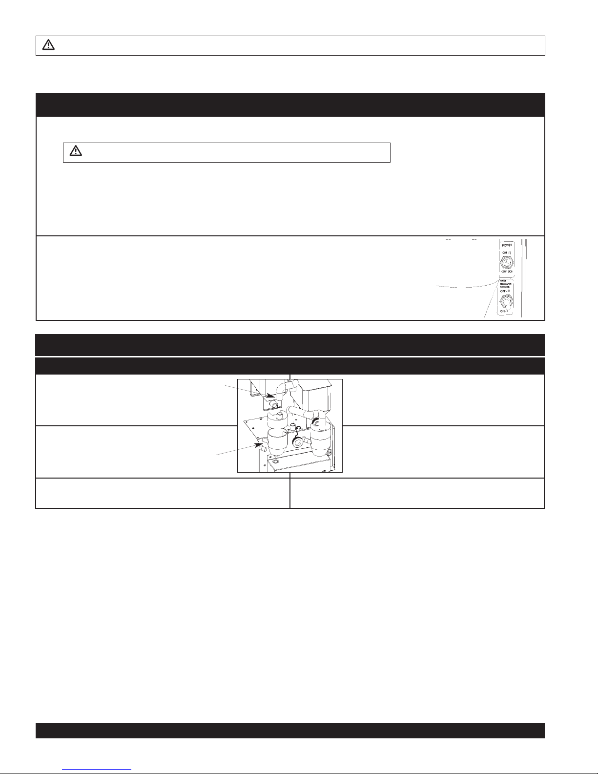
2.
Rinse out the funnel by placing the rinse switch (located to the right of the dispensing valves
when the door is open) in the ON position. Dispense one to two cupfuls until the water is clear.
Short bursts of dispensing may also help clean the chambers. When
complete, return the rinse switch to the OFF position.
WARNING: Disconnect power before servicing machine.
WARNING: Do not use a water jet to clean machine. Risk of electric shock.
Cleaning
Page 9

Model FDD2500 Page 9
Cleaning (cont.)
Weekly Cleaning (cont.)
Cleaning Hoppers – Disassembly Cleaning Hoppers – Reassembly
CAUTION: Do not wash hopper without first
disassembling.
IMPORTANT: All components must be completely dry prior
to reassembly.
1.
Open door, disconnect large hose from
funnel cover and then lift off funnel
cover.
1.
Place driveshaft bearing inside hopper
with threads going through hole in the
rear of the hopper.
2.
Lift off ring heater and set aside.
2.
Secure the bearing by attaching the palnut
to the bearing outside rear hopper opening. Use
one hand inside the hopper to push
the bearing outward while turning the
palnut clockwise.
3.
Lift open lid and remove coffee spill
pan.
4.
Remove the hopper from the cabinet.
3.
Install the auger spring driveshaft
and the auger spring by inserting the
flat end of the spring into the
5.
Remove the hopper
cover and empty
hopper contents.
4.
Insert assembly into lower front hopper
opening, making sure the threaded end of
the auger spring driveshaft completely
inserts into the plastic driveshaft bearing in
the rear of the hopper. The driveshaft
bearing threads should be accessible
6.
Remove the auger pinwheel by pulling it
forward while stretching out the sides of
the hopper.
5.
Place the washer over the driveshaft
bearing threads followed by securing
the drivelink onto the driveshaft bearing
by turning counterclockwise. Secure
the auger spring with one hand while
attaching the drivelink with the other.
7.
Remove the drivelink and washer at
the rear of the hopper by holding the
auger spring with one hand at the front
of the hopper while turning the drivelink
clockwise with the other hand.
6.
Replace the auger pinwheel making sure
the pins are securely positioned inside the
locator holes in the hopper.
8.
Remove the auger
spring and auger spring
driveshaft by pulling out
through the lower front opening of the hopper.
7.
Carefully fill
the hopper
with product
and replace
the cover.
9.
Remove the palnut at the
rear of the hopper by turning
it counterclockwise then remove
the driveshaft bearing from the
inside of the hopper.
8.
Reinstall hopper into the
machine, making sure it is
properly aligned.
10.
All parts in contact with food must be washed, rinsed,
sanitized, and air dried.
1
Install ring heater to front spout.
Open lid and install coffee
spill pan.
Driveshaft
Bearing
PULL
Auger Spring
Driveshaft
9.
10.
Install funnel cover with large
tube attached.
Page 10
Page 10 Model FDD2500
Prepare for Shipment
Important: Always completely empty water tank and PRODUCT HOPPERS prior to shipping unit. (See Draining
the Tank and Cleaning the Hoppers section).
NEVER SHIP UNIT WITH PRODUCT IN HOPPER OR WATER IN TANK –
THIS WILL CAUSE IRREPARABLE DAMAGE.
Draining the Tank
Always empty the tank before shipping.
WARNING: Draining of the tank should be performed by a qualified service technician. The tank contains
7.5 gallons (28.4L) of very hot water. May cause severe burns.
1.
Prepare a heat resistant container to drain 7.5 gallons
(28.4L) of hot water from the tank into.
5.
Pinch hose with fingers and
remove the hose clamp
and plug.
2.
Disconnect power to machine.
6.
Allow the tank to drain
completely.
NOTE: It may be necessary to pinch
the hose and stop the water before
container is full. Carefully re-install
plug, then empty container. Repeat
steps 4-6 to completely drain tank.
3.
Remove the drain tray and front access panel.
7.
Once the tank is empty, securely
replace the plug and clamp on
the end of the hose. Reposition
the drain hose.
4.
Locate the silicone drain hose.
Put the end of the drain hose
into the container. Secure the
end of the drain hose (i.e. with
tape) into the container.
8.
Reassemble the front access panel and drain tray.
Page 11
Model FDD2500 Page 11
REPLACING COMPONENTS
Tools Required: Phillips Head Screwdriver
1. Remove drain tray.
2. Remove 2 screws then remove front panel.
3. Remove 4 screws then remove lid.
4. Lift off side panels and/or rear panel.
5. Replace components as needed.
WARNING: Disconnect power before servicing machine.
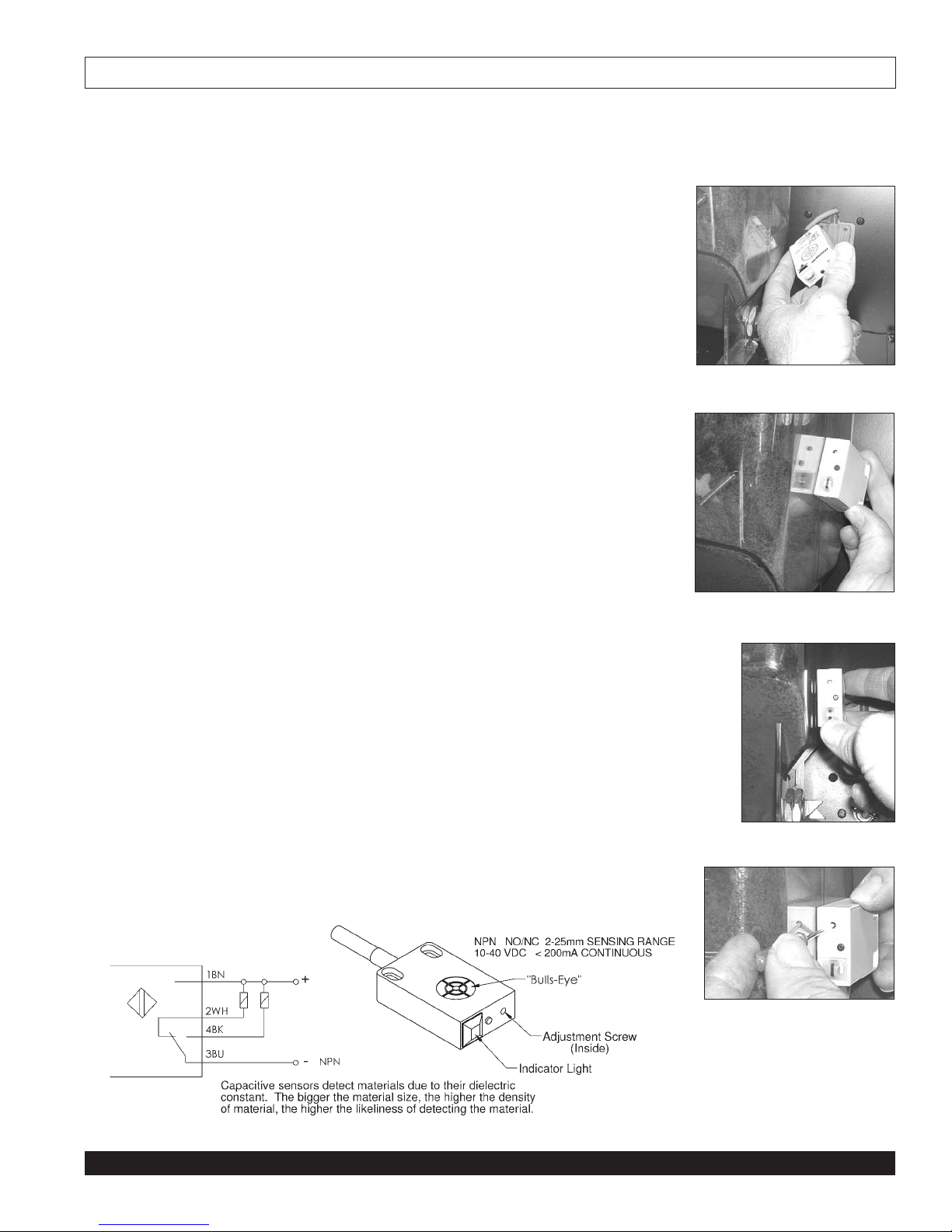
ADJUSTMENT TO “ADD PRODUCT” SENSORS
Capacitive Sensors might need to be adjusted if either situation occurs:
• Hoppers are full and display reads “ADD PRODUCT” when attempting a dispense.
• Hoppers are empty and display does NOT read “ADD PRODUCT” when attempting
a dispense.
Adjusting Capacitive Sensors:
1. Remove both hoppers.
2. Remove Sensor screws and gently pull sensor into cabinet. (see Figure 5)
3. Fill one hopper half full with product.
4. Hold sensor (“bulls-eye” side) flat against the full half of the hopper. (see Figure 6)
* Indicator light should be “ON”
5. Slowly move sensor away from the full half of the hopper.
* Indicator light should turn “OFF” 1/16” from hopper. (see Figure 7)
* If needed, adjust sensor with micro-screwdriver by gently turning adjustment screw.
(see Figure 8)
6. Hold sensor (“bulls-eye” side) flat against the empty half of the hopper. (see Figure 6)
* Indicator light should be “OFF”
* If indicator light is “ON”, adjust sensor with micro-screwdriver until light turns “OFF”.
7. Repeat steps 4 through 6 until no adjustment is needed.
Figure 5
Figure 6
Figure 7
Figure 8
REPLACING CONTROLLER
Tools Required: Phillips Head Screwdriver
1. Remove 4 screws and lift off lid.
2. Lift off right side panel.
3. Carefully disconnect each wiring connector from controller.
NOTE: Pull only on connectors. Do not pull on wires.
4. Carefully spring-back mounting clips and lift controller out of clips.
NOTE: Do not pull or press on sensitive controller components. Handle controller by
touching the edges.
NOTE: Reverse procedure to install controller. Make sure connector ramps and pins
are properly aligned before installing connectors.
Page 12

Page 12 Model FDD2500
Troubleshooting Guide
NOTE: The LCD display provides diagnostic feedback for determining the cause of fault or abnormal conditions. Error codes listed below are
stored in the controller memory and can be retrieved through the programming menu. Additional diagnostic LEDs are located on the controller
located behind the right side panel. See wiring schematics for LED locations and descriptions. Disconnect power before servicing machine.
Failure to do so can result in risk of electric shock.
Problem Possible Cause Solution
LCD display not illuminated
• Power switch turned “OFF”
• No power supplied to machine
• Ground Fault Circuit Interrupter (GFCI)
has tripped
• Machine control transformer circuit breaker
has tripped
• Fuse has blown.
• Faulty wiring connections
• Press and release “I/O” button located under the display.
• Turn power switch “ON”.
• Ensure machine is plugged in at wall socket.
• Reset GFCI (if applicable) at power outlet
• Check if green LED is illuminated on control board located behind
right panel. If LED is not illuminated, reset the control transformer
circuit breaker located next to the
control board.
NOTE: An overload condition can
reoccur. The overload
condition must be diagnosed and
corrected.
• Replace fuse. (see figure on right)
• Ensure all wiring connectors are
plugged into display board and
control board correctly. Check if any
wires have pulled loose from terminals.
LCD display shows error code (i.e. SC 1, 2, 3, etc.)
SC1: No Water Pressure
This feature is disabled and should not appear.
SC2: Reset Power • A fault condition described below has
occurred requiring power to be reset to
machine.
1) Water tank fill circuit has exceeded the
maximum run time (5 minutes)
2) A water tank overflow condition has
occurred
3) A water tank heating condition has
exceeded the water tank temperature set
point due to:
• Welded contacts on heater contactor
• For #1-3, turn power switch OFF for 5 seconds, then ON.
• Call Technical Service for assistance.
SC3: Low Water Level • Machine is filling the water tank
• Faulty water inlet valve electrical connections
• Faulty water inlet valve
• Insufficient water flow rate to machine (typically
during dispensing only).
• Allow machine to fill the water tank
• Ensure electrical leads are properly made to water inlet valve
• Check for power across water inlet valve terminals. If power is not
detected, replace water inlet valve.
• Allow water tank to fill. If problem continues, check for restrictions in
water line and check for proper water pressure (20-100 psi).
SC4: Thermistor Fail • Thermistor is disconnected
• Thermistor was subjected to sudden
temperature change (i.e. filling or
draining tank)
• Thermistor resistance valve is out of
“valid” range
• Check thermistor wiring connections
• Allow water temperature to stabilize, reset power to machine.
• Reset power first, if continues, check thermistor resistance (consult
factory for details), replace if necessary
SC6: Check Heating Water temperature has increased above set
point due to:
• Abnormal increase or decrease in water tank
temperature
• Welded contacts on heater contactor.
• Inlet water temperature must be below temperature set point
of water tank
• Check heater contactor for welded contacts, replace contactor if
necessary
SC9: Overflow condition • Water inlet valve weeping (leaking valve seal)
• Water inlet valve stuck open
• Loose water level probe connection
• Replace inlet valve
• Replace inlet valve
• Check connection to water level probe
Add Product • Hopper is empty
• Hopper is disengaged
• Capacitive sensor needs to be adjusted
• Fill hopper
• Make sure hopper is properly in place
• See “Add Product” Adjustment section on page 9.
Fuse
#63395
Page 13

Model FDD2500 Page 13
Problem Possible Cause Solution
LCD display shows “Standby” • Machine is in “STANDBY” mode • Press “I/O” on touchpad to activate machine. (Standby switch
acts as a power switch to the control module of the machine;
however, the machine is still powered up.)
No water or product is
dispensed
• Machine is in “STANDBY” mode
• Door is open
• Press “I/O” on touchpad to activate machine. (Standby switch
acts as a power switch to the control module of the machine;
however, the machine is still powered up.)
• A door interlock disables the dispense circuit when the door
is open. The door interlock switch is located behind the door
near the lower hinge and can be overridden by pulling the
switch plunger out. The switch will reset when the door is
closed.
No water is dispensed • Blockage in water delivery circuit • Check for kinked water delivery tubing, lime and scale blockage
to and from dump valve.
Powder not dispensing • Coffee dispense outlet clogged
• Hopper drive link not engaged with drive
motor
• Low or no product
• “Drink Strength” setting too low
• Clean hoppers according to cleaning procedure
• Remove and reinstall hopper to engage with drive motor
• Check product container for product
• Check “Drink Strength” setting (see programming guide for
setting Drink Strength)
Water overflows mixing funnel • Powder flow rate too fast – too much powder
to water ratio can prevent adequate mixing
resulting in blockage in mixing funnel
• Outlet is restricted
• Adjust powder flow rate to prevent blockage in mixing funnel
• Ensure mixing chamber outlets are free of blockage. Follow
rinse and cleaning procedure to prevent buildup of product in
mixing system.
Drink is too cold or hot • Check temperature set point and adjust as needed. (Refer to
Programming Guide for Thermostat Adjustment section)
Drink is too weak or strong • Check drink strength to desired taste. (Refer to Programming
Guide for Drink Strength Adjustment)
Water tanks boils water • Water temperature too high for elevation
of installation
• Adjust water temperature down. Refer to Thermostat
Adjustment section.
Troubleshooting Guide (cont.)
If you still need help, call our service department (Monday – Friday, 8 am – 6 pm EST) at (800) 695-4500 (USA and Canada
only) or (502) 425-4776 or an authorized service center in your area. Please have the model and serial numbers ready so
that accurate information may be given. Prior authorization must be obtained from Grindmaster Corporation’s Technical
Services Department for all warranty claims.
Page 14

Page 14 Model FDD2500
FDD2500 Assembly
5
2
38
33
4
20 63098 Logo "Grindmaster" PIC5/6
21 63446 Decal,Kraft Service
22 63358 Pad Top Foam FDD2500
23 63359 Pad Bottom Foam FDD2500
24 63357 Carton, FDD2500
25 63357A CARTON BOTTOM FDD2500
26 63360 Manual Installation FDD2500
27 63361 Manual Service FDD2500
28 100736 Decal,Flavor Strip Kraft Soluble
29 63451 Card Cleaning FDD2500
30 63450 Sheet Installation Check FDD2500
31 63427 Decal CDE for Box
32 92716 Warning Card Assy
33 61157 PLUG, HOLE 1/2 HEYCO #3065
34 71129 NUT, 8-32 KEPS SS
35 61303 Screw, #8 x 3/8 black trilobe
36 61186 Washer, #8 Int Lock
37 63402 Hose Adapter Asy FDD2500
18
12
ITEM NO. PART NO. DESCRIPTION
38 71676 Clamp,.671-.812,Nylon Hose
19
7
1
6
17
3
1 63200 Frame Assy FDD2500
2 63213 Tank Assy FDD2500
3 63211 Blower Assy FDD2500
4 63223 Panel Side Outer FDD2500
5 63224 Panel Rear Outer FDD2500
6 63225 Hopper Shelf Assy FDD2500
7 63238 Lid Assy FDD2500
8 63241 Splash Panel Assy FDD2500
9 63388 Decal Wiring Configs FDD
10 63245 Tray, Drain FDD2500
11 63246 Grid Drain FDD2500
12 63323 Control Brkt Assy FDD2500 Rt
13 63249 Contactor Brkt Asy FDD2500
14 63331 Door Assy FDD2500
15 61123-FDD-Left Hose 1-1/4 ID, 24"
16 61123-FDD-Right Hose 1-1/4 ID, 24"
17 62271 FDD Md Re Tube Silicone 1/2 x 3/4 X 8.75"
18 62271 FDD Rt Re Tube Silicone 1/2 x 3/4 X 6"
15
16
3
37
13
ITEM NO. PART NO. DESCRIPTION
8
FDD2500-1-M-B Shown
19 62271 FDD Lt Re Tube Silicone 1/2 x 3/4 X 8.75"
4
9
14
11
10
20
Page 15

Model FDD2500 Page 15
FDD2500 Frame Assembly
2
2
8
7
19
14
10
4
ITEM NO. PART NO. DESCRIPTION
1 63201 Shell Drawing for FDD2500
2 63202 Bracket Rear Corners FDD2500
9
9
3 63203 Bracket Front Left Corner FDD2500
4 63204 Bracket Front Right Corner FDD2500
13
18
5 63205 Bracket Hinge Top FDD2500
6 63206 Bracket Hinge Bottom FDD2500
12
7 63207 Bracket Upper Brace FDD2500
8 63208 Bracket Tank Cradle FDD2500
11
11
9 60380 RIVNUT, 3/8-16
10 63210 Panel Base Pan FDD2500
12
12
11 63119 Rail, Drain Tray PIC5/6
12 71256 Leg, 4" Plastic
13 62269 Fitting, 1/2" Barb SS
14 07920 Connector, 3/4 Conduit Metal Romex
15 61303 Screw, #8 x 3/8 black trilobe
16 61236 SCRW, 10-32X1/2 PH TR SS
17 61186 Washer, #8 Int Lock
18 63397 Plug, Hole, 1.75" Metal
19 63389 Decal, Field Wiring FDD
63200 - FRAME ASSEMBLY
12
5
5
6
3
Page 16

Page 16 Model FDD2500
FDD2500 Door Assembly
for models FDD2500-1-M-B
FDD2500-3-M-B
7
2
12
13
14
6
23
4
25
20
1
5
3
8
22
23
8
25
20
ITEM NO. PART NO. DESCRIPTION
ITEM NO. PART NO. DESCRIPTION
20 63384 Screw 1/4-20 x 1 SS Ph Hd
21 61303 Screw, #8 x 3/8 black trilobe
1 63332 Door Outer Plastic FDD2500
2 63253 Door Weldment FDD2500
22 63296 Harness Display-Switches FDD2500
23 W0611073 1/4-20 Nylon Lock-nut
3 63401 Display,LCD FDD2500
4 100117 Support,Circuit Board
24 71129 NUT, 8-32 KEPS SS
25 61334 Washer, Slinger
5 63255 Panel Access Rear Door FDD2500
6 100050-FDD Harness Cable Door FDD2500
26 63282 Switch Assy FDD
7 100068 Strain Relief,Heyco,SR5M-3
27 63283 Switch Assy FDD
28 63284 Switch Assy FDD
8 63281 Bracket Display Mtg FDD2500
9 62841 Touchpad, Adj only FDD
29 100736-C Label COFFEE (part of 100736)
30 63443 Label HOT WATER FDD
10 63258 Cover Display Plastic FDD2500
11 63286 Decal Display Cover FDD2500
31 100736-D Label DECAF (part of 100736)
12 62219 Spacer, Key Lock
13 100115 Latch,Thumb
19
14 62556 Cam,Straight,Hook,0.883
15 63289 Sight Gage Assy FDD2500
16 63287 Decal Shuttles FDD2500
17 63292 Decal Upper Door FDD2500
18 63288 Decal Brew Basket FDD2500
19 63298 Screw 1/4-20 x 1/2 SS Ph Hd
17
10
11
15
63331 - DOOR ASSEMBLY FDD2500
28
15
27
9
18
18
26
16
31
30
29
Page 17

Model FDD2500 Page 17
FDD2500 Door Assembly
for models FDD2500-1-3A-B
FDD2500-3-3A-B
12
13
14
31
7
2
6
5
3
22
ITEM NO. PART NO. DESCRIPTION
10
11
15
8
23
8
15
9
25
19
26
26 27
18
3-PORT
20
63434 - DOOR ASSEMBLY FDD2500
23
4
25
20
1
19 63298 Screw 1/4-20 x 1/2 SS Ph Hd
20 63384 Screw 1/4-20 x 1 SS Ph Hd
21 61303 Screw, #8 x 3/8 black trilobe
22 63438 Harness Switch 3-Port FDD2500
23 W0611073 1/4-20 Nylon Lock-nut
24 71129 NUT, 8-32 KEPS SS
25 61334 Washer, Slinger
26 63435 Touchpad Assy 3-Port FDD2500
27 63283 Switch Assy FDD
28 100736-C Label COFFEE (part of 100736)
29 63443 Label HOT WATER FDD
30 100736-D Label DECAF (part of 100736)
31 63452 Decal, Cleaning Door FDD
19
17
1 63332 Door Outer Plastic FDD2500
2 63253 Door Weldment FDD2500
3 63401 Display,LCD FDD2500
4 100117 Support,Circuit Board
5 63255 Panel Access Rear Door FDD2500
6 100050-FDD Harness Cable Door FDD2500
7 100068 Strain Relief,Heyco,SR5M-3
8 63281 Bracket Display Mtg FDD2500
9 62841 Touchpad, Adj only FDD
ITEM NO. PART NO. DESCRIPTION
10 63258 Cover Display Plastic FDD2500
11 63286 Decal Display Cover FDD2500
12 62219 Spacer, Key Lock
13 100115 Latch,Thumb
14 62556 Cam,Straight,Hook,0.883
15 63289 Sight Gage Assy FDD2500
16 63287 Decal Shuttles FDD2500
17 63292 Decal Upper Door FDD2500
18 63288 Decal Brew Basket FDD2500
18
16
30
29
28
Page 18

Page 18 Model FDD2500
FDD2500 Lid Assembly
FDD2500 Splash Panel Assembly
4
2
3
5
1
4
ITEM NO. PART NO. DESCRIPTION
1 63239 Panel, Lid, FDD2500
2 63322 Lid, Hinged Cover FDD2500
3 61792-flat HINGE, PWDR COATED SS 2 LEAF
6
4 61303 Screw, #8 x 3/8 black trilobe
5 61440 CAP, #8 SCREW SOFT
6 71582 Decal, Warning Disconnect
Page 19

FDD2500 Hopper Shelf Assembly
Model FDD2500 Page 19
37
37
25
3
43
46
43
9
40
10
2
17
33
42
42
15
19
21
36
23
11
11
51
11
38
27
31
51
24
16
15
20
36
1
29
30
6
6
63225 - HOPPER SHELF ASSEMBLY FDD2500
20
12
44
48
51
14
8
7
41 61303 Screw, #8 x 3/8 black trilobe
42 65131 HEATER RING ASSEMBLY
43 63383 Sleeve Hopr Nozzle FDD
44 63382 Fitting, Funnel Drop-in FDD
45 63229 Bracket Spout Mtg FDD2500
46 63393 Decal, "THIS SIDE UP"
47 07348-01 RIVET, POP MAXG 1/8 X 1/8 SS
48 63376 Diffuser, Flow FDD2500
49 63371 Decal, Caution Surfaces are Hot
50 71582 Decal, Warning Disconnect
51 71676 Clamp,.671-.812,Nylon Hose
52 70425 TERM, 1/4M INS QD 18-22 GA
10 63321 Bracket Dump Valve Mtg FDD2500
11 62251 Valve Dump Unvented Deltrol
53 61264 Plug, 3/16" Hole
12 62271 FDD Lt Fr Hose Silicone 1/2" x 3/4" x 4.25"
13 62271 FDD Md Fr Hose Silicone 1/2" x 3/4" x 6"
14 62271 FDD Rt Fr Hose Silicone 1/2" x 3/4" x 3.38"
15 61236 SCRW, 10-32X1/2 PH TR SS
16 63235 Spacer, Nylon,.194IDx.312ODx.125L
17 61228 Spacer, NYL HEY #334 SPU98
18 63068 NUT, 10-32 ESNA SS
19 61157 PLUG, HOLE 1/2 HEYCO #3065
20 100068 Strain Relief,Heyco,SR5M-3
21 100205 Fan,24VDC,60mm
22 63236 Cover Funnel FDD2500
ITEM NO. P ART NO. DESCRIPTION
1 63363 Bracket, Hopper Lower FDD
2 63362 Bracket, Hopper Upper FDD
3 63227 Hopper Asy .406P FDD2500
4 63228 Faucet Coffee/Water FDD2500
5 63318 Funnel Mixing FDD2500
6 63319 Fitting Plenum Hose FDD2500
7 63368 Lt 16 Tubing 1"ID PVC Flex Hose
8 63368 Rt 16 Tubing 1"ID PVC Flex Hose
ITEM NO. P ART NO. DESCRIPTION
9 61618 Motor,24VDC,Auger,145 RPM
23 63237 Bracket Fan Louver FDD2500
22
22
24 62218 Switch, Panel Mount Interlock
25 63268 Pan Coffee Catcher FDD2500
26 61440 CAP, #8 SCREW SOFT
27 61847 Switch,Toggle-Spst
28 61847-1 Nut, Switch, for 61847
29 61242 Label, Flush On/Off
5
30 61241 Label,Power
31 61466 Switch,Toggle 16 Amp Dpst
5
32 61466-1 Nut, Switch, for 61466
33 62286 Screw 6-32x1.25 PH PN SS (A601018)
44
45
34 61353 Screw,8-32 X 1/4" PH PN 18-8 SS
13
14
51
51
35 61250 Washer, #8 Split Lock
36 63266 Sensor Capacitive Carlo Gav
37 63267 Bracket Cap Sensor Mtg FDD2500
38 63317 Harness Hopr Brkt FDD
39 60145 6-32 x 3/4" SCREW, PH PN SS
40 71084 Screw 8-32 X 1/2 PH HD
51
51
4
4
4
Page 20

Page 20 Model FDD2500
FDD2500 Hopper Assembly
Page 21

20
Model FDD2500 Page 21
17
6
10
8
4
2
5
21
7
3
1
9
9
9
15
13
18
16
19
17
16
9
14
11
16
17
63213 - TANK ASSEMBLY,
ITEM NO. PART NO. DESCRIPTION
1 63214 Tank Weldment FDD2500
2 63355 Tank Gasket Tank 38"
3 63355 Baffle Gasket Baffle 20"
4 63220 Tank Lid Asy FDD2500
5 63222 Insulation Tank FDD2500
6 63294 Harness Htr 1-Ph FDD2500
12
7 62271 FDD Vent Tubing Silicone 1/2 x 3/4, 33"
8 70635 TERMINAL, 1/4-032 X 45DEG TAB
9 62269 Fitting, 1/2" Barb SS
10 63297 NUT, 10-24 ESNA SS
11 05826 FDD Short Tubing Silicone 3/8 x 5/8 x 5"
12 05826 FDD IValve Tubing Silicone 3/8 x 5/8 x 17"
13 61232 Plug,3/8 Barb
14 61152 Tee, 7/16" Barbed
15 63448 Decal,Tank Drain 5+ Gal
16 07327 Clamp,Hose,21/32ID,Heyco#2322
17 71676 Clamp,.671-.812,Nylon Hose
18 05826 FDD Drain Tubing Silicone 3/8 x 5/8 x 25"
19 62282 Gasket, Bulkhead
20 61353 Screw,8-32 X 1/4" PH PN 18-8 SS
21 60262,18 TAPE, ALUM HI-TEMP 18.25"
Page 22

Page 22 Model FDD2500
FDD2500 Tank Assembly – 3 Heater, 11.1kW
10
20
10
6
8
4
2
7
5
21
3
ITEM NO. QTY. PART NO. DESCRIPTION
1 1 63214 Tank Weldment FDD2500
2 1 63355 Tank Gasket Tank 38"
3 1 63355 Baffle Gasket Baffle 20"
17
1
9
9
9
19
9
17
16
11
16
14
16
18
15
12
4 1 63261 Tank Lid Asy FDD2500
5 1 63222 Insulation Tank FDD2500
6 1 63295 Harness Heater 3-Ph FDD2500
7 1 62271 FDD Vent Tubing Silicone 1/2 x 3/4, 33"
8 1 70635 TERMINAL, 1/4-032 X 45DEG TAB
9 4 62269 Fitting, 1/2" Barb SS
10 3 63297 NUT, 10-24 ESNA SS
11 1 05826 FDD Short Tubing Silicone 3/8 x 5/8 x 5"
12 1 05826 FDD IValve Tubing Silicone 3/8 x 5/8 x 17"
13 1 61232 Plug,3/8 Barb
14 1 61152 Tee, 7/16" Barbed
15 1 63448 Decal,Tank Drain 5+ Gal
16 4 07327 Clamp,Hose,21/32ID,Heyco#2322
17 3 71676 Clamp,.671-.812,Nylon Hose
18 1 05826 FDD Drain Tubing Silicone 3/8 x 5/8 x 25"
19 4 62282 Gasket, Bulkhead
20 6 61353 Screw,8-32 X 1/4" PH PN 18-8 SS
21 1 60262,18 TAPE, ALUM HI-TEMP 18.25"
16
13
17
63263 - TANK ASSEMBLY FDD2500-3, 15kW
Page 23

4
3
2
2
5
2
10
11
8
8
6
7
1
11
9
ITEM NO. PART NO. DESCRIPTION
1 63221 Lid Tank FDD2500
2 71147 GROMMET, SILICONE WHT
3 61108 PROBE, PIC
4 61128 Probe,Thermistor,12"
5 100160 Probe,Safety
6 62305 T-STAT, HI TEMP LIMIT
7 62239 BRKT, T-STAT CE MODEL
8 61353 Screw,8-32 X 1/4" PH PN 18-8 SS
9 62265 Element 240V 6.6kW
10 71585 Elbow,1/2mptx5/8barb 90 brass
11 71586 Nut,Lock,1/2fpt brass
Model FDD2500 Page 23
Page 24

Page 24 Model FDD2500
FDD2500 Tank Lid Assembly – 3 Heater
4
7
7
5
1
6
10
2
10
3
2
8
9
9
ITEM NO. PART NO. DESCRIPTION
10
1 63262 Lid Tank FDD2500
2 71147 GROMMET, SILICONE WHT
3 61108 PROBE, PIC
4 61128 Probe,Thermistor,12"
5 62305 T-STAT, HI TEMP LIMIT
6 62239 BRKT, T-STAT CE MODEL
7 61353 Screw,8-32 X 1/4" PH PN 18-8 SS
8 71585 Elbow,1/2mptx5/8barb 90 brass
9 71586 Nut,Lock,1/2fpt brass
10 62403 Element,240V, 3.7kW
Page 25

FDD2500 Control Bracket Assembly
Model FDD2500 Page 25
10
5
5
5
8
1
5
5
5
63323 - CONTROL BRACKET ASSEMBLY RT FDD2500
ITEM NO. PART NO. DESCRIPTION
1 63324 Bracket Control Right FDD2500
2 63345 Valve Inlet 120V Brass
3 100045 TRANSFORMER, 100VA CHASSIS MOUNT
4 63400 Controller FDD2500
5 61266 STANDOFF, RVRS EDGEMOUNT
3
9
2
6 63346 Fitting 1/2barb x 3/8nptm
7 63347 Fitting 3/8mfl x 3/8nptm
8 71620 Bushing, Hole Heyco 1.094" 2166
9 61303 Screw, #8 x 3/8 black trilobe
10 63293 Harness Right FDD2500 Control
6
9
4
7
Page 26

Page 26 Model FDD2500
ITEM NO. PART NO. DESCRIPTION
9
12
6
10
3
11
13
2
1
7
63280 - CONTACTOR BRACKET ASSEMBLY FDD2500-3
5
9
4
17
8
8
17
18
17
16
17
14
15
18
19
9
20
ITEM NO. PART NO. DESCRIPTION
1 63329 Bracket Control Left FDD2500
2 61131 Relay,12 vdc Coil
3 62262 Terminal Block 4-pole
4 61998 Contactor 4-Pole
5 63373 Transformer StepD 200VA 200/230/460-120
6 63349 Harness Left Side FDD2500
7 63350 Harness Term to Contact 3-Ph FDD
8 62332 Fuseholder, 30A 600V pnl mt
9 63395 Fuse 2 Amp Time Delay
10 63396 Decal, 2 Amp Fuse
11 07921 Lug Ground
12 60394 Bushing,Snap-7/8"OD x 3/4"
13 10073 Label, Ground Symbol
14 62286 Screw 6-32x1.25 PH PN SS (A601018)
15 60746 10-24 x 5/16" SCREW, PH PN 18-8 SS
16 70426 TERM, 1/4F INS QD 18-22 GA
17 61303 Screw, #8 x 3/8 black trilobe
18 60758 WASHER, #10 LOCK EXT SS
19 61159-4 Seal, Closed Cell Foam 4"
20 63449 Decal, Step-Down Wiring
1 63329 Bracket Control Left FDD2500
2 61131 Relay,12 vdc Coil
3 62262 Terminal Block 4-pole
4 62261 Contactor DPST 30A 120V
5 63373 Transformer StepD 200VA 200/230/460-120
6 63349 Harness Left Side FDD2500
7 62457 Harness Htr LCD, FDD 1-ph
8 62332 Fuseholder, 30A 600V pnl mt
9 63395 Fuse 2 Amp Time Delay
10 63396 Decal, 2 Amp Fuse
11 07921 Lug Ground
12 60394 Bushing,Snap-7/8"OD x 3/4"
13 10073 Label, Ground Symbol
14 62286 Screw 6-32x1.25 PH PN SS (A601018)
15 60746 10-24 x 5/16" SCREW, PH PN 18-8 SS
16 70426 TERM, 1/4F INS QD 18-22 GA
17 61303 Screw, #8 x 3/8 black trilobe
18 60758 WASHER, #10 LOCK EXT SS
19 61159-4 Seal, Closed Cell Foam 4"
20 63449 Decal, Step-Down Wiring
1
2
12
17
18
17
4
17
16
17
18
17
5
18
63249 - CONTACTOR BRACKET ASSEMBLY FDD2500-1
6
9
19
10
9
17
8
9
9
8
1
13
18
15
7
3
11
14
20
Page 27

FDD2500 Switch Assembly
FDD2500
Sight Gauge Assembly
1 63285 Plate, Switch FDD2500
8 62270 Pin, Pull Switch A551-015
Item No. Part No. Description
1 63285 Plate, Switch FDD2500
2 62260 Bezel, pull switch (A1101-020)
3
62266 Handle, Pull Switch - Coffee
62267 Handle, Pull Switch - Hot Water
62268 Handle, Pull Switch - Decaf
4 62281 Spring, Pull Switch A522120
5 61887 Switch, Snap Action Micro
6 61883 Bracket, Pull Switch Activation
7 63385 Rod, Pull Switch Modified A1101-019
8 62270 Pin, Pull Switch A551-015
9 71127 Screw 4-40 x 5/8 PH HD SS
10 71128 Nut, 4-40 SS Hex
11 71261 Nut, 8-32 SS ESNA
12 63447 Plate Striker
Model FDD2500 Page 27
FDD2500
Touchpad Assembly
2
1
ITEM NO. PART NO. DESCRIPTION
1 63437 Plate, Switch FDD 3-Portion
2 63436 Touchpad 3-Port FDD2500
2 62260 Bezel, pull switch (A1101-020)
3 62266 Handle, Pull Switch
4 62281 Spring, Pull Switch A522120
5 61887 Switch, Snap Action Micro
6 61883 Bracket, Pullswitch Activation
7 63385 Rod Pull Sw Mod 62259/A1101-019
1
9 71127 Screw 6-32 x 9/16" SS
10 71128 Nut 6-32 Hex SS
11 71261 NUT, 8-32 ESNA SS
12 63447 Striker Pullswitch
10
5
10
12
7
4
11
3
2
8
6
9
9
Page 28

Page 28 Model FDD2500
FDD2500 Blower Assembly
FDD2500 Hose Adapter Assembly #63402
(Optional)
2
ITEM NO. PART NO. DESCRIPTION
1 61103 Fan, Blower 120V .25A
2 63212 Bracket Blower Mt FDD2500
3 63260 Insulation Strip Blower FDD
4 61303 Screw, #8 x 3/8 black trilobe
1
4
3
4
63211 - BLOWER ASSEMBLY FDD2500
Page 29

FDD2500 Wiring Schematic
for all models
Model FDD2500 Page 29
FDD2500 WIRING SCHEMATIC
ALL VOLTAGE SUPPLIES
FAN
FAN
120V
STEAM EXHAUST
THERMISTOR
AUGER
MOTORS
Blk
M
Blk
M
RINSE
Blk
NL1
POWER SUPPLY
120V
TRANSFORMER
Capacitive
Sensor
Right
Capacitive
Sensor
Left
Blk
Red
Yel
L3
L2
PUR/WHT
BLK
120
24 VAC
RED
BN +
BLK SIG
WHT SIG
BLU -
BN +
BLK SIG
WHT SIG
BLU -
DOOR
SWITCH
OR
OR
Blk
2143
Right 0-24vdc
Middle
Augers:
Left
Ground
RED
BLK
TERMINAL
BLOCK
WHT
6587109
2A FUSE
2A FUSE
WHT
COM
COM
YEL
TOUCHPAD
Adj/Rinse
B
l
k
B
l
k
15
12111413
CONTROLLER
12VDC
MASTER
POWER
16
RED
BLK
H1
COM
L2
L1
H2
H3
H4
COM
120V
120V
WHT
BLK
B/W
WHT
WATER TANK
GROUND
OVERFLOW
LEVEL
FDD2500-1 only
SEE SWITCH
WIRING SCHEMATIC
DISPLAY
123
Red
Grn
Blk
Wh
CONNECT RED TO:
CONNECT RED TO:
CONNECT RED TO:CONNECT RED TO:
H2 FOR 208V SUPPLY
H2 FOR 208V SUPPLY
H2 FOR 208V SUPPLYH2 FOR 208V SUPPLY
H3 FOR 240V SUPPLY
H3 FOR 240V SUPPLY
H3 FOR 240V SUPPLYH3 FOR 240V SUPPLY
STEP-DOWN
TRANSFORMER
4
R/Wh
Br/Wh
Or
+24VDC
SEE OTHER SHEETS FOR HEATER CONFIGS
L1
L2
L3
CONTACTOR
120V
WHT
HI-TEMP LIMIT
THERMOSTAT
t°
BRN BRN
HEATER RELAY
NC
C
BLK/WHT
120V
YEL
RED
24VAC
24VAC
NO
12VDC
PUR
PUR
COM
Red
GND
Blk
CABINET
FAN
FDD2500 Wiring All
MJB, 6/29/05
PUR
PUR
R/Blk
Blu/Blk
Y/Blk
Blk
Blk
Blu/W
120V INLET VALVE
120V LEFT DISP VAL VE
120V MIDDLE DISP VALVE
120V RIGHT DISP VALVE
Page 30

Page 30 Model FDD2500
1 Heater, 1 Phase, 60 Hz, 240/208 VAC Configuration
for models FDD2500-1-M-B
FDD2500-1-3A-B
(1) 6.6 kW 240 VAC ELEMENT
6.6 kW (28 AMPS) @ 240 VAC (2 WIRE + GND)
5.0 kW (24 AMPS @ 208 VAC (2 WIRE + GND)
6.6 kW (28 AMPS) @ 120/240 VAC (3 WIRE + GND)
5.0 kW (24 AMPS @ 120/208 VAC (3 WIRE + GND)
HE
ATER #
1
TOP VIEW OF WATER TANK
CONNECT RED WIRE TO:
CONNECT RED WIRE TO:
CONNECT RED WIRE TO:CONNECT RED WIRE TO:
"H2" FOR 208V SUPPLY
"H2" FOR 208V SUPPLY
"H2" FOR 208V SUPPLY"H2" FOR 208V SUPPLY
"H3" FOR 240V SUPPLY
"H3" FOR 240V SUPPLY
"H3" FOR 240V SUPPLY"H3" FOR 240V SUPPLY
460VH4230VH3200V
H2
STEP-DOWN
TRANSFORMER
120 VAC
TO CONTROL CIRCUIT
H1
COM
RED
BLACK
2A FUSE
2A FUSE
N
N
L1L3L2
L2
L1
TERMINAL
BLOCK
L3
T2
T1
CONTACTOR
L2L1
FDD Manual Wiring 1-Ph
Page 31

Three Heater Option Configuration Hookup Diagram
for models FDD2500-3-M-B
FDD2500-3-3A-B
Model FDD2500 Page 31
H
EATER #3
FDD2500-3
3-HEATER WIRING HOOK-UP
3
NOTE: MACHINE IS EQUIPPED WITH
(3) 3.7kW 240 VAC ELEMENTS WHICH
CAN BE CONFIGURED TO ACHIEVE
VARIOUS WATTAGE OUTPUTS PER
THE CHART BELOW DEPENDING ON
POWER SOURCE AVAILABLE.
CONNECT RED WIRE TO:
"H2" FOR 208V SUPPLY
"H3" FOR 240V SUPPLY
H4 H3
460V
H2
230V
200V
STEP-DOWN
TRANSFORMER
H
EATER #2
H
EATER #1
TOP VIEW OF WATER TANK
#10 AWG BLACK HEATER WIRES
ARE CONNECTED TO CONTACTOR
CONNECTIONS "T1,T2,T3,T4"
PER THE CHART BELOW TO
ACHIEVE THE SERIAL PLATE
VOLTAGE AND WATTAGE
CONFIGURATION
2A FUSE
2A FUSE
H1
COM
RED
BLACK
3
2
2
1
1
N
L1
NL1
L2
L3
L2
L3
1
1
T2
T1
CONTACTOR
L2
L1
TERMINAL
BLOCK
3
2
2
3
T4
T3
L4
L3
# OF ELEMENTS
UTILIZED
SINGLE PHASE
0.5
1
1.5
2
0.5
1
1.5
2
THREE PHASE (DELTA CONFIGURATION)
3
3
VOLTAGE
208
208
208
208
240
240
240
240
208
240
120 VAC
TO CONTROL CIRCUIT
AMPSWATTS
1390
2780
4140
5560
1850
3700
5550
7400 30.9 1,2
8340
11100
6.7
13.4
19.9
26.8
7.7
15.5
23
23.2
26.8
CONNECT NUMBERED HEATER WIRES TO
CONTACTOR TERMINALS PER CHART BELOW
1,2
1,2
1,2
1,2
1,2
T1
T2
1
1
1
1
2
1
1,3
1,2
2
1
1,3
1,2
1,3
1,3
T3
1,2
2,2
2,3
3,3
1,2
2,2
2,3
3,3
2,3
2,3
T4
3,3
3,3
-
-
3,3
3,3
-
-
-
-
FDD2500 Wiring 3-Ph
Page 32

Page 32 Model FDD2500
Wiring Schematic within Door
for models FDD2500-1-M-B
FDD2500-3-M-B
Page 33

Model FDD2500 Page 33
Wiring Schematic within Door
for models FDD2500-1-3A-B
FDD2500-3-3A-B
W/R
header 2
BLK
TOUCHPAD
W/R
W/ORG
W/BLU
PUR/W
M
N/O
W/ORG6BLK/W
W/ORG
23
45
LEFT
BRN/W
PINK
TOUCHPAD
32
L
S
132
RIGHT
TOUCHPAD
I/O
">"
"+"
324 3
768
9
S
M
21
PUR
4
14
BLU/W
2610
GRN
12
"-"
16 20
5437891513 1917
header 1
2422 26
W/ORG
30
11
header 2
211 25272931
28
header 1
L
6
5
18
2 x 16 backlit LCD display
RED
3412
WH
GRN
WHT
GRY
TO MAIN
ORG
BLK
R/W
W/BLU
COM
W/R
BOARD
WHT
BRN
ORG/W
W/R
SETTINGS
W/BLU
FDD2500-WIRING DISP 3A
FDD2500-*-3A-B
3-PORTION COFFEE & DECAF
MANUAL HOT WATER
SCHEMATIC WITHIN DOOR
CENTER SWITCH
MANUAL FREE-FLOW
CAP THIS TERM.
GRY/WHT
Page 34

Page 34 Model FDD2500
Page 35

Model FDD2500 Page 35
Page 36

Grindmaster® Coffee Grinders and Brewers • Espressimo® Espresso Machines • Crathco® Hot Beverage Dispensers
Crathco® Cold and Frozen Beverage Dispensers • American Metal Ware® Coffee and Tea Systems
Tel (502) 425-4776 • Fax (502) 425-4664 • 1-800-695-4500
P.O. Box 35020 • Louisville, KY 40232 • USA
www.grindmaster.com • email: info@grindmaster.com
© Grindmaster Corporation, 2005 0705 Form # AM-342-02
PRINTED IN USA Part #63361
 Loading...