

Page 1
ET1 Espresso and Tea Machine
Operator Manual
Grindmaster-Cecilware
4003 Collins Lane, Louisville, KY 40245 USA
Phone: 502.425.4776 Toll Free: 800.695.4500
Fax: 502.425.4664
Web: gmcw.com Email: info@gmcw.com
Safety Information..................2
Specifications...........................4
Overview..................................5
Installation...............................7
Programming ..........................7
Operation ................................8
Cleaning...................................9
Adjustments ..........................10
Draining.................................12
Troubleshooting....................12
Parts Diagram and List..........13
Wiring Diagram.....................20
Thank you for purchasing this quality espresso machine. For your safety and the safety of others, read all warnings
and the operator manual before installing or using the product. Properly instruct all operators. Keep training
records. For future reference, record serial number here:
Table of Contents
©2018 Grindmaster-Cecilware
Printed in Taiwan
0218 Form # GC-300-01
Part # 390-00168
Grindmaster-Cecilware provides the
industry’s BEST warranty. Visit gmcw.com
for warranty terms and conditions.
Model ET1
Activate your warranty now at
http://gmcw.com/warranty-registration
Page 2
GB Series Cecilware
®
2
To reduce risk of electrical shock, do not remove or open cover. No user-serviceable parts inside. Repair should
be done by authorized service personnel only.
The appliance is not intended for outdoor use. Do not expose to rain or direct sunlight.
Do not clean with pressurized water or use in an area where pressurized water may be used.
Cleaning and maintenance shall be made only by properly trained persons with supervision.
This appliance is not intended for use by persons with reduced physical, sensory, or mental capabilities, or lack
of experience and knowledge, unless they have been given supervision or instruction concerning use of the
appliance by a person responsible for their safety.
Children should be supervised to ensure that they do not play with the appliance.
Do not alter or deform the power cord or plug in any way! Altering or deforming the plug may cause electrical
shock, damage unit, and will void warranty.
To reduce risk of explosion or fire, do not use near combustibles.
Installation of this appliance should be performed by qualified service personnel only. Improper installation
could result in electrocution.
Shock hazard. Disconnect power before adjusting steam pressure.
To reduce the risk of electrical shock, unplug the dispenser power cord before repairing or replacing any internal
components of the unit. Before any attempt to replace a component, be sure to check all electrical connections
for proper contact. Only a qualified service technician should perform electrical and mechanical adjustments or
repairs.
WARNING
Safety Information
2 Grindmaster
®
ET1 Espresso Machine
Important Safety Information
This is the safety alert symbol. It is used to alert you to potential personal injury hazards. Obey all safety messages
that follow this symbol to avoid possible injury or death.
For your safety and the safety of others, read all warnings and the operator manual before installing or using
the product.
DANGER: This term warns the user of imminent hazard that will result in serious injury or death.
WARNING: This term refers to a potential hazard or unsafe practice, which could result in serious injury or death.
CAUTION: This term refers to a potential hazard or unsafe practice, which could result in minor or moderate
injury.
NOTICE: This term refers to information that needs special attention or must be fully understood.
Page 3
ET1 Espresso Machine Grindmaster
®
3
For safe and proper operation the appliance must be placed in a stable, vertical position.
To reduce risk of serious burns or scalding, do not place hand or other body parts under dispenser while product
is brewing.
Always unplug unit from power supply before servicing.
Surfaces are hot and can cause burns. Use caution especially in the areas of the steam wand, hot water wand,
and brewing group.
Packaging material, including plastic bag and Styrofoam, can be dangerous and should be kept out of reach of
children.
To reduce risk of electrical shock, do not touch machine with wet hands or feet.
Steam wand, hot water wand, and brewing unit are very hot. Use caution when operating unit to prevent burns.
Unit is very hot. Use caution when turning on programming switch to prevent burns.
Dispenser surfaces and water inside dispenser are very hot. Use caution when draining unit to prevent burns.
Never turn on drain valve when there is pressure in the boiler.
CAUTION
Observe machine voltage configuration. Do not apply improper voltage to machine or damage to machine may
occur. For use on individual dedicated branch circuit only. Do not use extension cord.
Make sure that the outlet
the unit plugs into is grounded.
Check rating marking on nameplate to be sure electric lines match voltage, phase,
and amperage requirements of appliance.
Follow national and local electrical codes.
Do not use the machine and turn off the power during water outage.
This equipment must be installed in compliance with applicable Federal, State, and/or Local plumbing codes
having jurisdiction. This product requires an approved back flow prevention water device, such as a double
check valve, to be installed between the machine and the water supply.
Please follow maintenance and cleaning instructions specified in this manual to ensure the best operation
efficiency of machine.
Using filtered and softened water will reduce scaling in the boiler and lengthen the serviceable life of the
machine. Replace filter regularly, depending on volume and quality of water used.
If machine will not be used for a long time, evacuate the water inside the piping completely. Do not expose
machine to freezing temperature if any water is in machine.
Do not block air intake or outlet vents on the machine.
Turn the power off and release all boiler pressure if the machine is to remain idle for an extended period of
time.
After machine power has been switched off, always let the machine set for at least 3 seconds before restarting.
NOTICE
Page 4
4 Grindmaster
®
ET1 Espresso Machine
Rough-In Drawing
Specifications
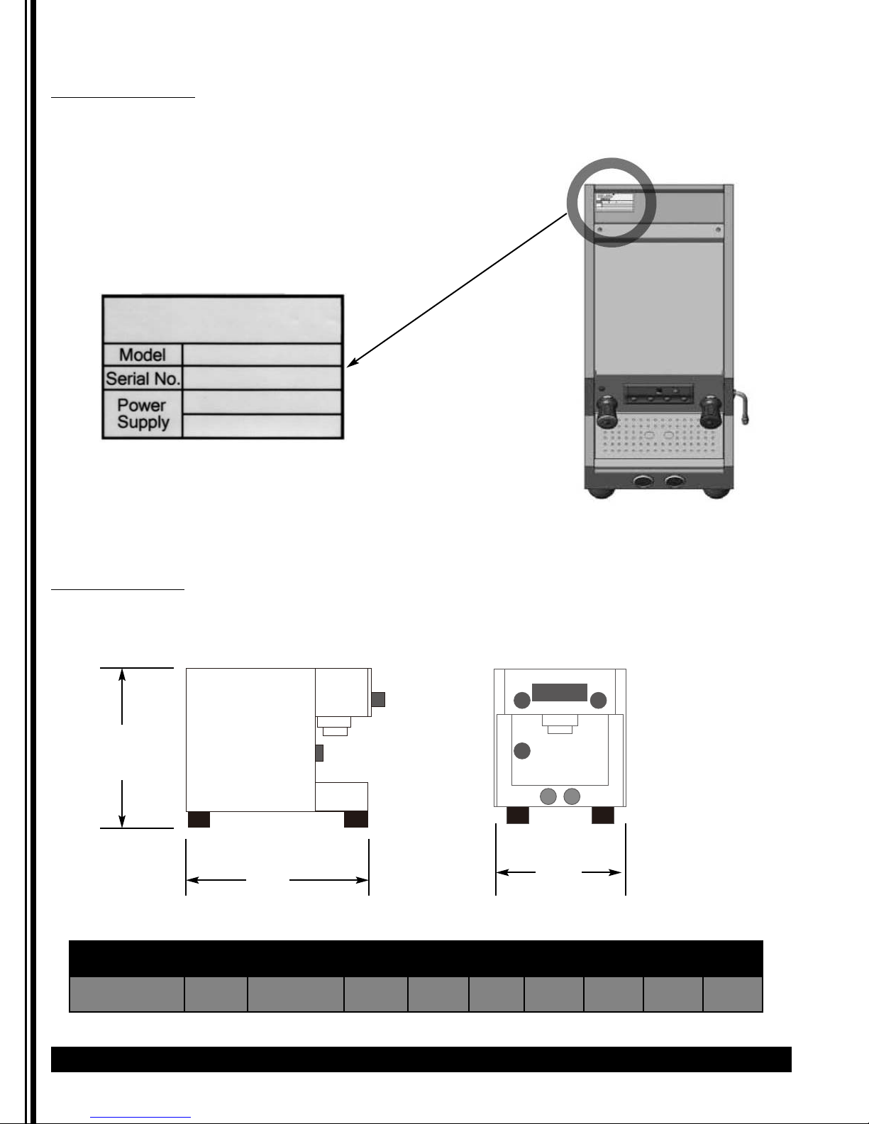
Identification Label
Every machine has an identification label placed on the to of the machine as illustrated below. The label includes
information of model number, voltage, serial number, wattage, and its certificate. Do not remove this label.
Model Group Boiler Voltage Watts Hertz Weight Dimensions
Capacity A B C
ET1 1 3L 220/240 1500 50/60
26 kg
57 lbs
37 cm
15 in
50 cm
20 in
43.6 cm
17 in
37 cm
15 in
50 cm
20 in
43.6 cm
17 in
Figure A
Figure B
Page 5
ET1 Espresso Machine Grindmaster
®
5
Specifications (continued)
Specification Table
Overview
Model Number of Heads Boiler Capacity Electrical
ET1 1 3L 220/240V / 1Ph / 50/60 Hz / 1500 W
Side Clearance required - 4" (10.2 cm)
Rear Clearance required - 4" (10.2 cm) for water and electrical connections
Water connection size - 3/4" GHT, 1/2" water line required
Water pressure between 20 PSI and 90 PSI (138 kPa - 621 kPa). Use regulator if higher pressure.
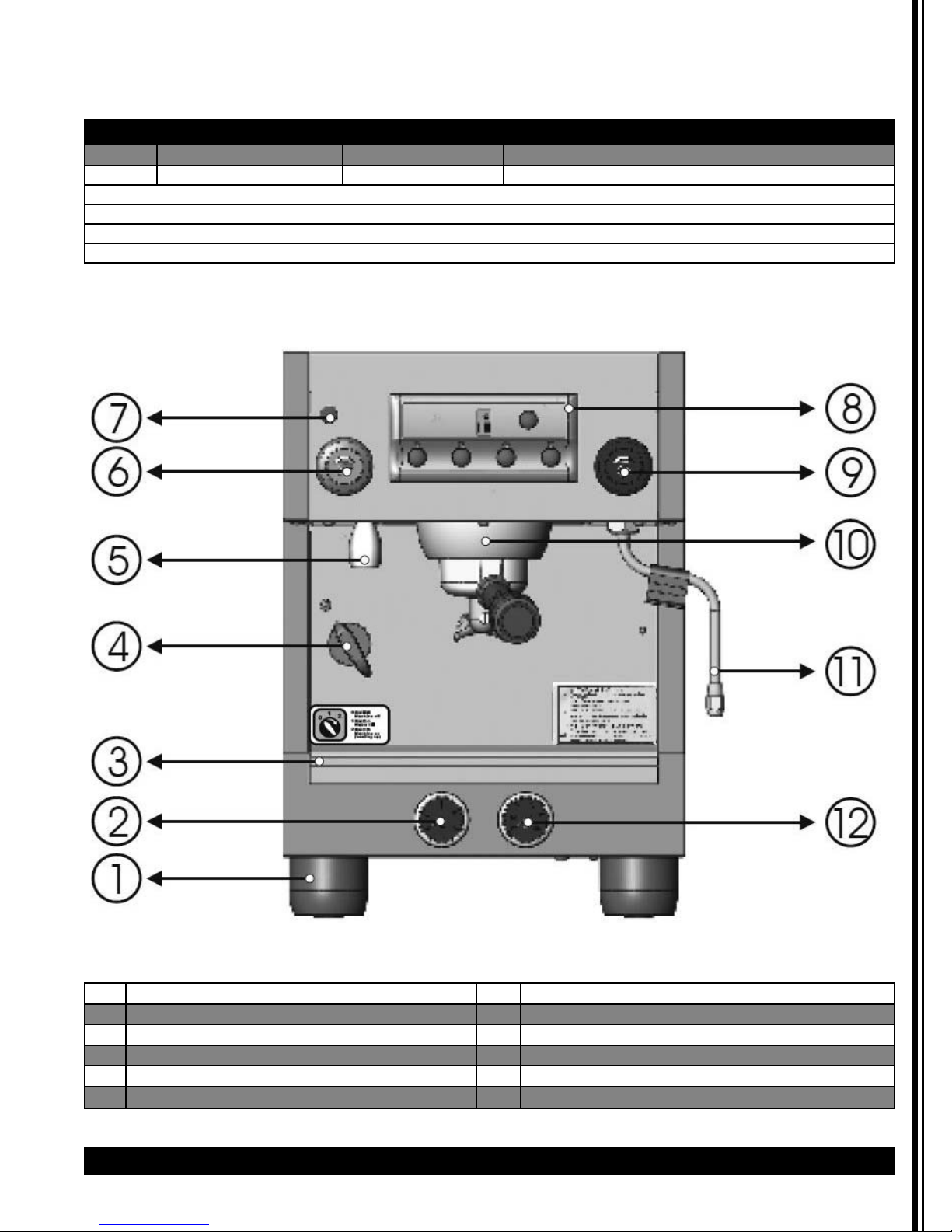
1 Foot 7 Power Indicator
2 Water pressure gauge 8 Control Panel
3 Water tray 9 Steam control knob
4 Power Switch 10 Brewing group
5 Hot water outlet nozzle 11 Steam tube
6 Hot water control knob 12 Steam pressure gauge
Figure C
Page 6
6 Grindmaster
®
ET1 Espresso Machine
Overview continued
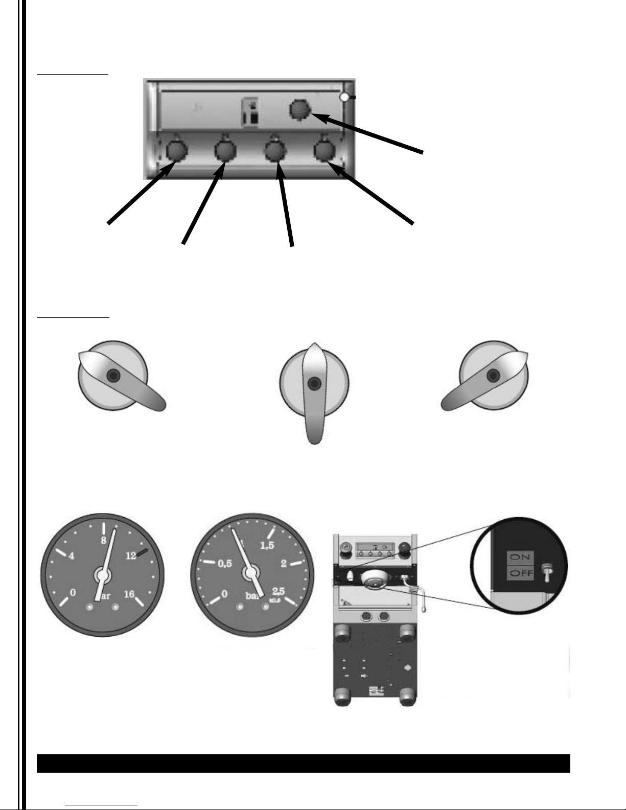
Control Panel
Figure D
1 - Coffee single portion
2 - Coffee double portion
3 - Tea single portion
4 - Tea double portion
Continuous Flow Button
Power Switch
The power switch has 3 settings.
POSITION 0
OFF
POSITION 1
WATER FILL
POSITION 2
MACHINE ON (HEATING)
Figure E
Figure F
Water Pressure
9 bars
Steam Pressure
1.0 bar
Figure G
Page 7

Unpacking Instructions
Carefully unpack the machine and inspect immediately
for shipping damage. The packaging may contain
unattached parts. Your machine was shipped in a carton
designed to give it maximum protection in normal
handling. It was thoroughly inspected before leaving
the factory. In case of damage, contact the shipper, not
Grindmaster-Cecilware.
NOTICE:
This equipment must be installed in
compliance with applicable Federal, State, and/or Local
plumbing codes having jurisdiction. This product requires
an approved back flow prevention water device, such as
a double check valve, to be installed between the
appliance and the water supply. If a check valve type
backflow preventer is used for water supply protection,
a screen of at least 100 mesh (100 strands per 1.0 in [25
mm]) shall be installed immediately upstream. The screen
shall be accessible and removable for cleaning or
replacement. (Required for NSF approved water hookup.)
Incoming pressure should be greater than 20 psi and not
more than 90 psi.
• A filtering system is recommended to remove odors
and inhibit lime and scale build up in the unit.
• In areas with extremely hard water, a water softener
must be installed in order to prevent a malfunctioning
of the equipment and in order not to void the warranty.
Unsoftened water will decompose dissolvable minerals
and turn to limescale after boiling. The limescale will
reduce the machine’s thermal efficiency and machine’s
lifetime.
NOTICE: Do not use extension cord. Make sure that the
outlet the unit plugs into is grounded.
Check rating
marking on nameplate to be sure electric lines match
voltage, phase, and amperage requirements of
appliance.
Connections
1. When operating the machine for the first time or
replacing water softener and filtration system,
remove the water inlet tube and allow it to drain
for about one minute in order to get rid of
impurities from the water.
2. Connect a 1/2" diameter water line to the water
supply connection.
3. Open the water shut-off valve and check
connections for leaks. DO NOT over-tighten. Verify
water supply.
4. Connect 18mm diameter drain line to bottom,
center of machine.
5. Attach appropriate plug to cord. Power source
corresponds to the electrical rating shown on the
serial tag on unit. Plug the ET1 Espresso machine
into a dedicated power supply outlet.
6. Turn the Power Switch on front of unit to POSITION
1 (see Figure E). The tank will fill in approximately
2-3 minutes.
7. Press continuous flow button on control panel (see
Figure D) to verify water flow.
8. Verify water pressure is 9 bars (see Figure F).
Confirm water pressure before turning on
heating element.
9. Turn the Power Switch on front of unit to POSITION
2 (see Figure E). Do not operate the machine
before the steam pressure reaches 1.0 bar (i.e. the
needle of steam gauge is within the blue zone).
10. In case of need to adjust the pressure, refer to
Adjustments section.
11. Machine does not come pre-programmed. It is
necessary to program buttons before operation.
Programming
Control Panel
No default coffee output setting is provided. Settings
must be made manually during set-up.
1. With power switch turned to position 2, turn on the
programming switch (see Figure G). The LED of
buttons 1 - 4 on the control panel will be lit.
2. Press continuous flow button. Buttons 1 - 4 will
flash.
3. Place measuring cup under the brewing group.
Press and hold down the first button. Release when
the required amount of water for the first pulse is
reached. Continue to press and release button 1
until the desired number of pulses and water
output is obtained. Then press the continuous flow
button. The first button is programmed. The first
button’s light will be off and the other three
buttons will still be lit. Maximum number of pulses
is 10.
4. Continue programming other buttons. Turn
programming switch to OFF when completed. Each
time the programming switch is turned ON, it will
reset the buttons. Maximum is 10 pulses.
ET1 Espresso Machine Grindmaster
®
7
WARNING: ELECTRIC SHOCK HAZARD!
Installation of this appliance should be performed by
qualified service personnel only. Improper installation
could result in electrocution.
Installation
CAUTION: BURN HAZARD
Steam wand, hot water wand, and brewing unit are
very hot. Use caution when operating unit to prevent
burns.
CAUTION: BURN HAZARD
Unit is very hot. Use caution when turning on
programming switch to prevent burns.
Page 8

8 Grindmaster
®
ET1 Espresso Machine
NOTICE: To avoid overheating, electric wires should
be kept untangled and free of obstructions. Don’t block
air intake or outlet vents on the machine. Never cover
or otherwise prevent the free flow of air across the cup
warmer.
NOTICE: Do not use cleansers, bleach liquids, powders
or any other substance containing chlorine. These
products promote corrosion and will pit the stainless
steel. USE OF THESE PRODUCTS WILL VOID THE
WARRANTY.
Panel
1. Place an appropriate quantity of ground coffee or
tea leaves in the Portafilter and tamp firmly. Clean
all residual matter from the rim and sides of the
filter. This is to ensure a good seal and full pressure
when brewing coffee or tea, and prolong the
lifetime of the gasket. Attach the Portafilter to the
machine by rotating until it locks in place.
2. Place cup(s) or glass(es) under spout(s).
3. Either press desired portion button or press and
hold the continuous flow button until desired
portion is dispensed. To stop flow at any time, press
and release continuous flow button (see Figure D).
4. Move cup(s) or glass(es) to side and remove
Portafilter. Dump grinds/leaves. Carefully hold
Portafilter near group head and rinse using the
continuous flow button water. Use extreme caution
to avoid burns. Then, fit empty Portafilter to the
brewing group to store and keep warm.
Steam Wand:
This can be used by turning the knob counterclockwise,
which allows for a varied amount of steam or by pulling
out the handle which will dispense the maximum
amount of steam.
1. To drain condensate, ensure steam wand is pointed
toward the drain grid and pull handle out briefly to
dispense a small amount of steam.
2. Pour cold milk in a pitcher and place steam arm into
pitcher. Hold pitcher with one hand and turn on
steam, either by twisting to add a controlled
amount or pulling knob out to add steam at full
pressure.
3. Remove pitcher.
4. Wipe arm and nipple clean with soft cloth
moistened with sanitizer solution after each use.
After wiping, pull steam knob to release a steam
burst through the tube to remove any residual milk
remaining in the nozzle.
NOTICE: Remove the pitcher from the steam tube
after foaming milk. Failure to do so may draw liquid
from the pitcher into the steam tube, risking machine
component contamination.
Hot Water
1. Turn the hot water knob counterclockwise to obtain
hot water through hot water wand (on right side
of machine). Hot water output will increase the
further the hot water knob is turned. Turn the knob
clockwise to reduce/stop hot water output.
2. You can also pull the knob straight out in order to
obtain hot water. (See Figure H)
Operation
CAUTION: BURN HAZARD
Steam wand, hot water wand, and brewing unit are
very hot. Use caution when operating unit to prevent
burns.
Figure H
Page 9

ET1 Espresso Machine Grindmaster
®
9
Power Off
To extend your boiler’s serviceable life, when the
machine is expected to sit idle for a couple of days, turn
power OFF and open the steam output to discharge
steam pressure in the boiler. Continue until the pressure
gauge reading falls to zero and steam discharge ends.
Once complete, empty and clean the water tray.
NOTICE: Leave the steam output setting open when
steam discharges. Steam output should remain open
until the machine is turned on and hot water begins
dripping from the steam tube.
Cleaning
NOTICE: All sanitizing agents in the food zone must
comply with 21 CFR 178.1010. Sanitize all food
dispensing units periodically. All parts to be sanitized
must be cleaned first. Cleaning and sanitizing frequency
must follow state and local health department
regulations.
NOTICE: Wipe the accessories with a soft cloth or
specific detergent powder. Don’t use scrub sponge or
wire brushes.
After each brewing
1. Carefully hold Portafilter near group head and rinse
Portafilter using the continuous flow button water.
Water is hot - use extreme caution.
2. Wipe arm and nipple clean with soft cloth
moistened with sanitizer solution after each use.
After wiping, pull steam knob to release a steam
burst through the tube to remove any residual milk
remaining in the nozzle.
Daily
Exterior:
Wipe the machine exterior with soft, slightly
dampened cloth daily before starting operations. If
necessary, a mild, non-corrosive cleaning agent may
be applied to the cloth.
NOTICE: Do not spray cleaning fluid directly on the
espresso machine to avoid corrosion or possible
electrical damage.
Back flushing:
1. Remove screw (E), shower screen (D), and plate (C)
from the group head (be careful, metal components
may be hot). (see Figure I)
2. Place the rubber disc in Portafilter (see Figure J),
and apply about 2-3 grams of espresso machine
detergent/sanitizer on top of rubber disc. Attach
the Portafilter to the group head and check for
tightness.
3. Press any button and continuous flow button
simultaneously to start automatic back flushing
function. This auto back flushing system will
complete 10 cleaning cycles.
4. After automatic back flushing cycle is complete,
rinse Portafilter and rubber disc with water from
the continuous flow button until water in Porta
Filter appears clean.
5. Replace rubber disc on Portafilter, then place
Portafilter on the group head and press any button
and continuous flow button simultaneously to start
automatic back flushing function to rinse. This auto
back flushing system will complete 10 cleaning
cycles.
6. Screw (E), shower screen (D), and plate (C) should
be cleaned and sanitized with the Portafilter, steam
wand nipple and hot water wand sprayer.
Operation (continued)
Figure I
Figure J
Page 10

10 Grindmaster
®
ET1 Espresso Machine
Cleaning and sanitizing portafilter:
Notice: To avoid damage, do not immerse espresso
Porta Filter handle in water. Do not put group gasket
(item B from Figure I) in water or any liquid detergent.
1. Disassemble Portafilter. (see Figure K)
2. Remove sprayer from hot water wand.
3. Remove nipple from steam arm.
4. Add loose group head parts [screw (E), shower
screen (D), and plate(C) from Figure I].
5. Use brush to clean and wash parts in detergent or
espresso urn cleaner/sanitizer. DO NOT immerse
Portafilter handle. (see Figure L)
6. Rinse parts.
7. Prepare a sanitizing solution in accordance with
local health department regulations. You may also
refer to the US Food and Drug Administration
regulation 21 CFR 178.1010 “Sanitizing Solutions”
and US Environmental Protection Agency 40 CFR
18.940 “Tolerance exemptions for active and inert
ingredients for use in antimicrobial formulations
(Food-contact surface sanitizing solutions)”.
8. Follow the instructions provided with the sanitizing
agent.
9. Let all sanitized parts drain and dry naturally. DO
NOT WIPE THEM DRY.
10. Reassemble parts.
Drain Tray and Discharge Trough:
1. Remove and wash the drain tray after stopping use.
2. Wipe and remove sediments in the discharge
trough with a wet cloth and wash with hot water
to clear the discharge tube.
3. If water does not discharge properly, place a
teaspoon of detergent into the discharge trough
and flush with hot water to dissolve residual oils in
the tube.
4. Reassemble after the water tray has dried.
Adjustments
The rest of this manual contains information to aid the
service technician who is maintaining this equipment.
This section has information on performing common
service tasks.
Water Pressure Adjustment
The water pressure has been factory adjusted to 9 bar
(the recommended pressure). After machine starts up
and water refills, press continuous flow button and read
pressure on pressure gauge to determine if the
indicator is in blue zone (8-10 bar) as shown in Figure
M.
If the pressure is not in the blue zone, adjust pressure
as shown below:
1. Remove left side panel (see Figure N, next page).
2. Attach Portafilter into the brewing group with
filled ground coffee.
3. Press continuous flow button. Turn screw clockwise
as shown in Figure O on next page to increase
pressure; turn counterclockwise to reduce pressure.
Handle
Do not immerse
Liquid
Figure L
Cleaning (continued)
Figure K
Water Pressure 9 bars
Figure M
WARNING: SHOCK / BURN HAZARD
Only a qualified service technician should perform
electrical and mechanical adjustments or repairs.
Page 11

ET1 Espresso Machine Grindmaster
®
11
Steam Boiler Pressure Calibration
Steam boiler pressure is controlled by the pressure
switch. The pressure inside the boiler continues to rise
as the water is heated by the heating elements.
Reducing pressure will reduce temperature, while
increasing pressure will increase temperature. The
steam boiler has been factory adjusted to 1 bar, (the
recommended pressure). Check if the pressure on the
pressure gauge is 1 bar or in the blue zone (1-1.4 bar)
(see Figure P). if so, you don’t need to adjust the
pressure. If there is a need to change the pressure,
follow below procedure for calibration:
1. Turn off machine.
2. Remove top cover of machine, and locate the
pressure switch in the center, back area (see Figure
Q).
3. Use slotted screwdriver to adjust the pressure as
shown in Figure R. Turn screw clockwise to increase
pressure, or counterclockwise to reduce pressure. A
complete screw turn results in about 0.1 bar
variation.
Figure N
Figure O
Figure Q
Figure R
Steam Pressure 1.0 bar
Figure P
Use 14mm wrench to turn the safety
screw counterclockwise to loosen it.
Use 10mm wrench to turn the
adjustment screw counterclockwise
to decrease the water pressure.
Adjustments (continued)
WARNING: SHOCK HAZARD
Unplug machine before adjusting steam pressure.
Page 12

12 Grindmaster
®
ET1 Espresso Machine
If espresso machine will not be used for an extended
period, will be stored, or transported, drain tank to
prolong life and prevent damage from freezing.
1. Turn off the machine, and release all the pressure
from boiler by turning on the steam knob(s).
2. After the steam is completely released and the
pressure on steam boiler pressure gauge reads “0”,
remove drain tray and locate drain valve under
drain tray. Turn on drain valve to drain water out of
boiler. Drain valve is on when it is parallel to pipe.
NOTE: Please DO NOT turn off the steam knob after the
steam is released for storage. Keep the steam knob on.
When you re-start the machine, do not turn off the
steam knob until you see water drop from the steam
wand. This is to balance the boiler pressure.
3. Turn off drain valve when water stops flowing into
waste cup. Drain valve is off when it is
perpendicular to pipe.
CAUTION: BURN HAZARD
Dispenser surfaces and water inside dispenser are very
hot. Use caution when draining unit to prevent burns.
CAUTION: BURN HAZARD
Never turn on drain valve when there is pressure in
the boiler.
Troubleshooting
Before you call for help, please read the following:
WARNING: To reduce the risk of electrical shock, unplug the dispenser power cord before repairing or
replacing any internal components of the unit. Before any attempt to replace a component, be sure to check all
electrical connections for proper contact. Only a qualified service technician should perform electrical and
mechanical adjustments or repairs.
Note: Wait at least 3 seconds to restart the machine after turning it off to ensure previous error stored in memory
is cleared.
If you need help, call Grindmaster-Cecilware Technical Service Department, (502) 425-4776 or (800) 695-4500 (USA
& Canada only) (Monday through Friday 8 AM - 6 PM EST). Please have the model and serial number ready so
that accurate information can be given.
Prior authorization must be obtained from Grindmaster-Cecilware for all warranty claims.
Grindmaster-Cecilware provides the industry’s BEST warranty. Visit our website at gmcw.com for
warranty terms and conditions.
Draining
INDICATION PROBABLE CAUSE SOLUTION
All lights on control • After two minutes of • Water level probe not • Make sure that the water
panel turn on water input, indicator functioning properly. valve is turned on and
still does not show a there is water flowing
rise in machine water into machine.
level. It will take more • Water intake solenoid is • Turn off machine. Restart
than two minutes to out of order. after 3 seconds.
replenish water when
•
Input water flow has been • Turn water supply on.
the machine is used interrupted.
for the first time.
All lights on control • No water output • Coffee grounds are too • Adjust fineness of coffee
panel flash from brewing group. fine. grinds.
• Brewing for a long • Water intake solenoid is • Turn off machine. Restart
time without reaching out of order. after 3 seconds.
setup value. • Flow meter is out of order. • Press any key to eliminate
the breakdown signal,
and notify qualified service
technician.
Page 13

ET1 Espresso Machine Grindmaster
®
13
Parts Diagram and List
怑䓐㨇䧖İġŎŐŅņō烉ņŕIJ
1
2
3
4
5
6
7
8
9
10
13
12
11
14
15
16
17
Item Part # Description Item Part # Description
1 MUG TRAY 10 BASE
2 LEFT SIDE PLATE 11 ANTI-SLIP MATS
3 GAUGE BRACKET 12 FOOT
4 F SERIES STEAM HOT WATER VALVE BRACKET 13 RIGHT PLATE
5 MOISTURE BOARD 14 BOILER BRACKET
6 FORMER TRIM 15 REAR COVER
7 FRONT TRIM 16 F1 DRAINAGE STENT
8 F SERIES WATER TRAY 17 PRESSURE SWITCH BRACKET
Body Parts Assembly
A060648-00
A070030-00
A060364-01
A060649-00
Page 14

14 Grindmaster
®
ET1 Espresso Machine
Parts Diagram and List (cont.)
1
2
12
11
10
9
8
7
6
5
4
3
Item Part # Description Item Part # Description
1 HING SPRAY HOSE-BRAIDED STEEL(2400MM) 7 01312L TEFLON WASHER
2 410-00547 MOTOR/230V 8 BRASS CONNECTOR
3 MOTOR SHOCK FOOT 9 BRASS CONNECTOR
4 SPRING WASHER M6 10 FILTER
5 STAINLESS STEEL HEXAGON NUTS M6 11 01323 NBR O-RING
6 01368L PUMP PO074 12 HING SPRAY HOSE-BRAIDED STEEL(350MM)
Motor Pump Assembly
Page 15

ET1 Espresso Machine Grindmaster
®
15
Parts Diagram and List (cont.)
怑䓐㨇䧖İġŎŐŅņō烉ņŕIJ
䇰㫉
20
4
4
19
4
17
18
23
22
21
24
25
26
27
28
29
30
31
32
33
34
4
35
5
6
7
1
2
3
4
8
4
9
4
10
11
12
13
14
15
16
Item Part # Description Item Part # Description
1 PRESSURE SWITCH BRACKET 19 STEAM INTAKE
2 BRANCH TEE FLARE CONNECTOR 20 BOILER ASSEMBLY
3 COOKING HEAD BACK HOSE 21 410-00493 PRESSURE BRASS BALL VALVE STRAIGHT
4 TYPE L BRASS FLARE CONNECTOR 22 SUB-GROUP OF THE CONNECTING TUBE BOILER
5 THREE-WAY SHUTTLE VALVE 23 METER OUTLET GROUP
6 01319L EXHAUST MANIFOLDS 24 01325L FLOW METER DOSER
7 410-00551 3/8" LEVEL PROBE SET 95L 25 TYPE I FLARED CONNECTOR
8 LARGE BOILER INLET PIPE GROUP 26 410-00550 FLOW METER GAUGE
9 LEFT HOT BRASS GROUP 27 FLOWMETER INLET PIPE GROUP
10 COOKING HEAD INTO THE PIPE GROUP 28 410-00358 S.C.N.R.DOSER VALVE
11 BAROMETER TUBE GROUP 29 PRESSURE GAUGE TUBE SET
12 COOKING HEAD BACK TO THE TRACHEA GROUP 30 PRESSURE SWITCH GROUP
13 RIGHT STEAM PIPE GROUP 31 M10 STAINLESS STEEL SPRING WASHER
14 CHECK VALVE RELIEF PIPE GROUP 32 SOLENOID VALVE INLET GROUP
15 VALVE BRASS GROUP 33 PRESSURE GAUGE CONNECTOR
16 HEATING ELEMENT 34 MA-TER PRESSURE SWITCH
17 TYPE I BRASS CONNECTOR 35 410-00548 SOLENOID VALVE
18 410-00549 STEAM MANIFOLD GROUP
Boiler Hydraulic Circuit
Page 16

16 Grindmaster
®
ET1 Espresso Machine
Parts Diagram and List (cont.)
2
16
14, 15
13
12
11
1
3
4
5
6
7
8
9
10
Item Part # Description Item Part # Description
1 GROUP CAP 9 01301L SHOWER DELIVERY
2 TEFLON GASKET(PLUS COPPER) 10 01302L INXO SHOWER SCREW M5*15
3 01382L FILTER NOZZLE 11 410-00506 STAINLESS STEEL SOCKET HEAD CAP M4*15
4 01381L COOKING COPPER NOZZLE HEAD 12 STAINLESS STEEL SPRING WASHER M4
5 STAINLESS STEEL SOCKET HEAD CAP M5*10 13 410-00552 SOLENOID VALVE ODE
6 R SERIES COFFEE COOKING HEAD(COPPER 14 TYPE I FLARED CONNECTOR
7 01300L FILTER SUPPORT RUBBER/SEAL HOLDER 15 WATER INLET CONNECTOR
8 410-00501 GROUP PLATE 16 R SERIES COFFEE COOKING HEAD SHIMION PADS
Distribution Group Assembly
Page 17

ET1 Espresso Machine Grindmaster
®
17
Parts Diagram and List (cont.)
怑䓐㨇䧖İġŎŐŅņō烉ņŕIJ
䇰㫉
20
21
22
23
24
26
27
28
29
30
31
1 12
2
3
4
5
6
7
13
8
9
10
11
14
15
16
17
18
19
33
14
22
32
25
Item Part # Description Item Part # Description
1 01333L STEAM KNOB CAP 18 NOZZLE UNDER HOT WATER
2 01312L TEFLON WASHER 19 410-00362 HOT WATER NOZZLE GROUP
3 01380L COMPRESSION SPRING 20 STEAM HOT WATER VALVE BASE
4 01379L STEAM SPRING WASHER 21 STEAM WATER BASE NUT
5 01313L O-RING 22 410-00512 STEAM PIPE HOT WATER NOZZLE VALVE SCREW
6 STEAM PIPE BASE 23 01336L KNOB
7 STEAM PIPE 24 01311L R STEEL CIRCLIP
8 410-00516 SEAL SCALD 25 01337L STEAM PIPE HOT WATER NOZZLE VALVE ASSEMBLY
9 O-RING 26 01308L SI GASKET
10 01383L STEAM NOZZLE 27 STEAM HOT WATER VALVE SPINDLE
11 410-00554 STEAM PIPE ASSEMBLY 28 01310L COPPER WASHER
12 01332L HOT WATER KNOB CAP 29 COMPRESSION SPRINGS
13 HOT WATER OUTLET GROUP 30 STEAM HOT WATER VALVE SCREW BASE
14 01309L O-RING 31 01335L STEAM HOT WATER VALVE SCREW
15 HOT WATER NOZZLE 32 WASHER
16 410-00553 O-RING 33 TIGHTING GASKET
17 BUBBLER
Water and Steam Assembly
Page 18

18 Grindmaster
®
ET1 Espresso Machine
Parts Diagram and List (cont.)
怑䓐㨇䧖İġŎŐŅņō烉ņŕIJ
䇰㫉
8
7
6
5
9
17
10
11
12
13
14
15
16
5
1
2
3
4
Filter Holder Assembly
Item Part # Description Item Part # Description
1 01346L SILICA GEL WASHER 10 O-RING 49*3.0
2 01356L FILTER 2 CUPS 11 TO FILTER BASE (TEA BAG)
3 01352L FILLTERHOLDER SPRING 12 H TYPE STOPPER GASKET
4 01350 FILTER CUP HOLDER 13 STAINLESS STEEL STOPPER
5 01354L FILTER CUP HANDLE 14 STEAM TAP SPRING
6 01358L DUAL CUP SPOUT(OPTIONAL) 15 ADJUST VALVE
7 01348L FILTER 1 CUP 16 FILTER CUP HOLDER
8 BIG FLAT HEAD SCREW (STAINLESS) 17 STRESS BRASS SPOUT
9 FILTER (TEA BAG)
Item Part # Description Item Part # Description
1 WATER PRESSURE 4 410-00533 SPRING WASHER M10
2 BAROMETER 5 410-00532 DRAIN TANK
3 410-00534 NUT M10
怑䓐㨇䧖İġŎŐŅņō烉ņŕIJ
䇰㫉
1
2
5
4
3
Other
A020087-00
Page 19

ET1 Espresso Machine Grindmaster
®
19
Parts Diagram and List (cont.)
31
32
27
30
29
28
26
25
24
23
22
21
20
19
18
17
16
1
2
3
4
5
6
7
8
9
10
36
37
38
33
34
35
11
12
13
15
14
Electrical System Assembly
Item Part # Description Item Part # Description
1 CLIP CORE 21 MAIN POWER HEATING PIPELINE
2 410-00359 POWER INDICATOR 220V 22 MAIN POWER SWITCH SET
3 TIN PILL HEAD ST1/8*1/4 23 MAIN POWER LINE GROUP
4 OPERATION BOX 24 INDUCTANCE GROUNDING WIRE
5 YELLOW ZINC LARGE FLAT 1/8*1/4 25 RESONATORS & FILTERS
6 IC BOARD CONTROL PANEL 26 MAIN POWER LINES
7 410-00555 OPERATION PANEL BOX GROUP 27 ANTI-INTERFERENCE SIGNAL LINES
8 OPERATION PANEL UP COVER (COFEE+TEA) 28 WATER LEVEL PROBE WIRE
9 ROUND ALUMINUM 29 T1 FLOWMETER LINE
10 OPERATION NAMEPLATES 30 FLOWMETER CONNECTOR
11 WIRE RETAINER 31 SOLENOID VALVE CONNECTOR
12 SETTING SWITCH STICKERS 32 410-00528 COFFEE SERIES CONTROL PC-MAINBOARD
13 POWER SWITCH STICKER 33 CONTROL BOX WITHOUT IC BOARD (UP COVER)
14 410-00529 SET MOTOR SWITCH LINE 34 STAINLESS STEEL FLAT HEAD ST3.5*19
15 PRESSURE SWITCH HEATING PIPELINE 35 STAINLESS STEEL SOCKET HEAD CAP M4*20
16 POWER SWITCH KNOB 36 410-00526 CONTROL PC-MAINBOARD
17 MAIN SWITCH COVER 37 TIN PILL HEAD ST1/8*1/4
18 PUMP POWER CORD 38 CONTROL BOX WITHOUT IC BOARD (DOWN
19 POWER SWITCH n/a OPERATION PANEL
20 PRESSURE SWITCH LINE n/a KEYSTROKE
Page 20

Wiring Diagram
©2018 Grindmaster-Cecilware
Printed in Taiwan
0218 Form # GC-300-01
Part # 390-00168
J15
J19
Flowmeter
J16
J7
J17
J20
J5
Water level probe
B5
J9
Keyboard
J12
J8
J14
J11
H2
J13
J18
J10 SP1
J4
Set motor switch
B1
J3
B2
B3
J1
B4
A120005-00
A1
J2
Solenoid ValvĞ
(Water in)
Solenoid ValvĞ
(Water out)
ET1 Circuit Diagram
Heating pipe 1.25KW
1 Phase
220V-50/60 Hz
Power Switch
7
5
3
1
Pressure Switch
8
6
4
2
M
Motor & Pump
Connector
L
N
E
Connector
 Loading...