

Page 1
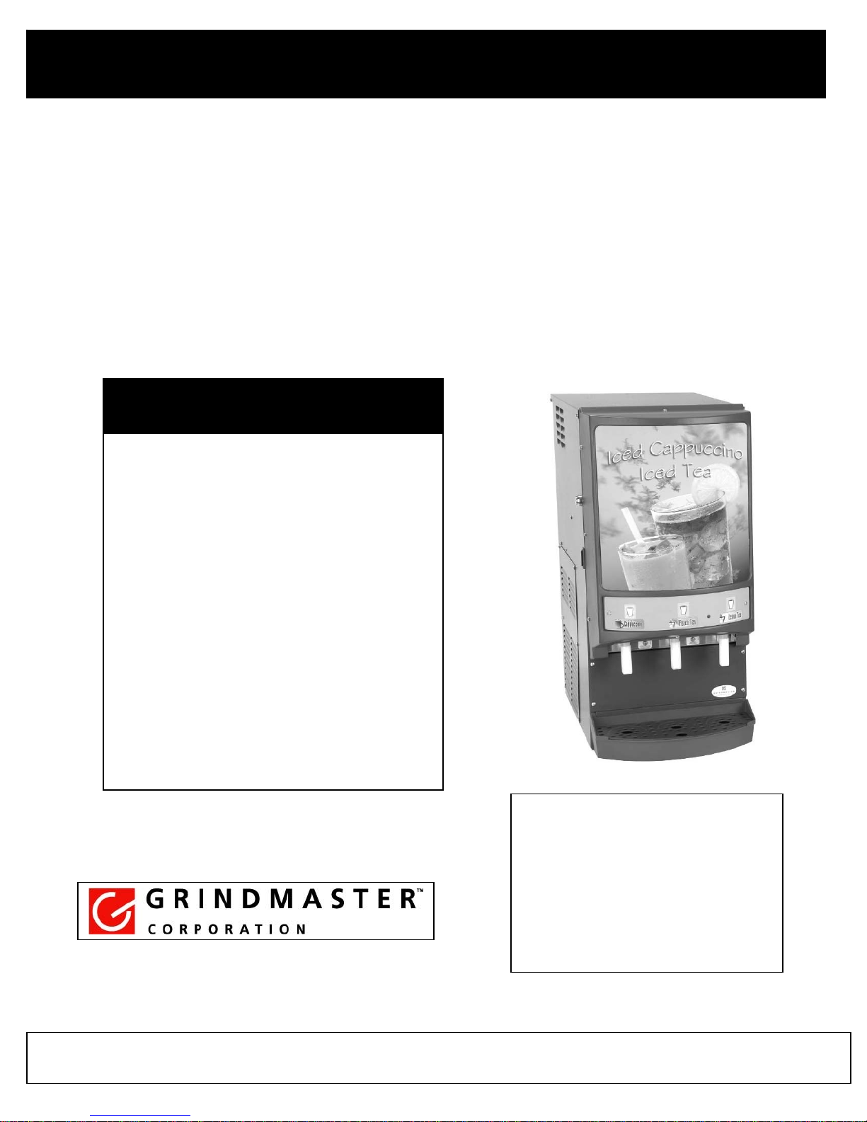
Crathco Cold Powdered Beverage Dispensers
Service Manual
For
Models CP3, CP3A, CP33A,
CP3E, CP3AE, CP33AE
Table of Contents
Warning Labels
Installation and moving
Cleaning of unit
Dispensing
Portion and Drink Strength Adjustment
Prepare for shipment
Refrigeration System Maintenance
Preventative Maintenance Checklist
Troubleshooting
Replaceable parts Illustration
Controller and Refrigeration Info
Exploded Views
Wiring Diagrams
Page 3
Page 4-5
Page 6-7
Page 8
Page 9
Page 10
Page 11
Page 12
Page 13
Page 14-15
Page 16-17
Page 18-34
Page 35-37
©Grindmaster Corporation, 2007 0807 Form CC-352-03
Printed in USA
Grindmaster Corporation
4003 Collins Lane
Louisville, KY 40245
(800) 695-4500 (US & Canada only)
Fax (502) 425-4776
www.grindmaster.com
USA
Page 2

Page 3

Warning Labels
r
Part # 71582 – Warning label located on the lower right hand corner of the lower
front panel. “Disconnect power before servicing unit”
Part # 61848 – Warning label located on plenum cover under hoppers on inner
front tray. “Do not pour liquids into tray. Failure to comply will damage the
dispenser and void the warranty” It is also written in French and Spanish as well.
Part # 65288 – Warning label on upper front panel. “Important to prevent
overflow, release button when cup is 2/3’s full. This will produce a full cup”
Crathco Cold Powdered Beverage Dispense
PAGE 3
Page 4

Installation
Installation Notice
A water filter is recommended for the water supply to the dispenser, especially in areas where water contains a
high level of minerals such as calcium or other solids. Over long periods of time, calcium deposits build on
heat-exchanger coils and will lower the cooling capacity of the system. Calcium build-up will also occur on the
strainers enclosed in the inlet of the water valves as well as in the inlet of the dispensing valve.
The cooling system is provided with copper coils, designed to last the life of the dispenser. However, some
chemicals in treated or non-treated water, specifically chlorine and sulfur (sulfide) may shorten the life of the
coils. The initial investment in the filtering system will pay for itself in product quality and by ensuring a longer
life for the machine.
Water Inlet Connection
The National Sanitation Foundation requires the following for an NSF approved water hook-up:
1. A quick disconnect water connection or enough coiled tubing so the machine can be moved for cleaning
underneath without the water being disconnected from the machine.
2. An approved backflow prevention device, such as a double check valveis to be installed between the
machine and water supply.
3. Water pipe connections and fixtures directly connected to potable water supply shall be sized, installed, and
maintained in accordance with applicable codes.
Unpacking
To remove the machine from the box:
1. Remove staples from the top of the box.
2. Remove top padding from the top of box.
3. Using a utility knife, cut the box vertically from the top to the bottom starting at the top rear corner.
4. Cut the box in the front corners.
5. Remove the machine.
If you intend to keep the box:
1. Tilt the box with the machine 45° and remove staples from the bottom - bring the bottom box flaps up.
2. Tilt the box to the opposite side and remove remaining staples - bring the bottom box flaps up.
3. Set the box to normal position and slide the box upward.
4. Remove drip tray accessories from the bottom pad.
5. Remove the machine from the pad.
Start-up Procedure
1. Install drain tray in front of machine.
2. Flush the water line to purge any debris from the supply line.
3. Connect the 1/4” male flare adapter (provided) to the inlet valve on the back of the
machine.
4. Connect the water line to the connection and turn the water supply on.
a. Minimum water pressure to the machine: 20 psi (1.3 bar))
b. Maximum water pressure to the machine: 100 psi (6.8 bar)
5. Plug the power cord into the proper electrical outlet (either 115V 60 Hz or 220V, 50 Hz).
115 Volt power requirements are as follows 115Volt, 60 Hertz 518 watts , 4.6 amperes.
Note : Take precautions to insure the electrical circuit is not overloaded. It is advised
that this unit be installed on a dedicated electrical circuit.
6. Turn the power switch to the “ON” position and allow the water tank to fill. The machine will make a subtle
hissing sound when this occurs. Allow 1-3 minutes for fill time depending on inlet water pressure.
Page 4 Crathco Cold Powdered Beverage Dispensers
Page 5

Installation (cont.)
7. After the water tank has filled, allow 90-150 minutes to build ice-bank depending on ambient temperature
and the initial water temperature. (Green ready light will illuminate when compressor stops and the
machine has reached full cooling capacity.)
8. Remove the powder hoppers, rotate the dispense elbow to the “UP” position and fill with desired powder
product. IMPORTANT: Make sure that the auger inside inside the hopper is correctly installed prior to
filling. Reinstall powder hoppers. Turn dispense elbow down toward the mixing funnel to rest at a 7 o’clock
position.
9. Peel protective film off the merchandiser cover and install graphic. Install flavor decals as needed.
NOTE: If water supply is allowed to run dry, watchdog timer circuit may disable fill circuit. Ensure adequate
water supply for machine, then reset machine by turning power switch “OFF” for 3 seconds and then turning
the power switch back “ON”.
MOVING MACHINE, TANK DRAINING INSTRUCTIONS
Turn the power switch off first.
1. If the CP3 machine needs to be moved, tank draining instructions are as follows.
Indentify the right hand side panel and remove it. Locate the ice bank tank drain hose. Pull the
hose out to allow it to drain into a bucket
Remove blank off plug from hose. The tank will drain all liquid out into the bucket (about 2
gallons of liquid).
The ice bank (about 1.5 quarts) will remain in the tank, to remove proceed as follows.
Place blank off plug back into drain line. Turn power switch on and allow the tank to
refill with water.
Turn off the power switch off and repeat the draining procedurell and drain the tank at
least 3 times to insure all ice is melted away from coils
2. If machine will be exposed to temperatures below 32 degrees F (less than 0 degrees C) all of the water
from the machine must be removed to avoid water freeze-up and damage to the valves.
Follow above procedure for draining the ice bank tank and in addition.
Turn off water supply and remove water supply line from the water inlet valve.
Power up machine.
Apply pressurized air to the inlet valve and at the same time push dispensing button. Repeat
this for each dispensing head. Some water will splash at the dispensing funnel and nozzle.
Air pressure should not exceed 4.1 bar (60 psi).
Crathco Cold Powdered Beverage Dispensers Page 5
Page 6
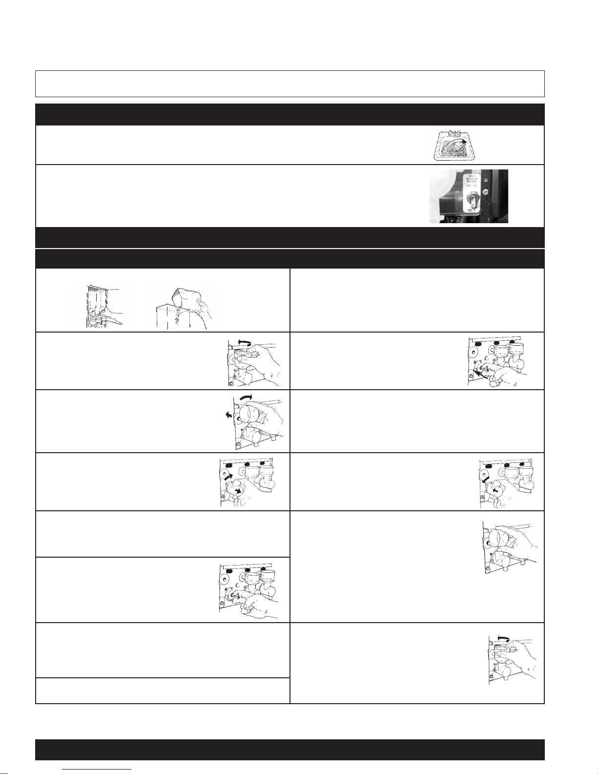
Daily Cleaning (2 times per day)
Empty drip pan as needed and wash in a solution of dish detergent.
Rinse out the whipper chambers by placing the rinse switch (located on the right of the
dispensing valves when the door is open) in the “ON” position. Dispense one to two cups until
the water is clean. Short bursts of dispensing may also help clean the chambers more
effectively. When completed, return the rinse switch to the “OFF” position.
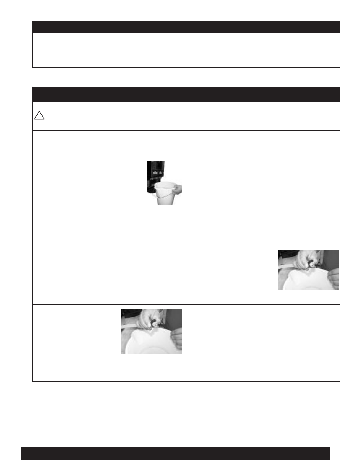
Daily Cleaning (once at the end of the day)
Cleaning the Chambers - Disassembly Cleaning the Chambers - Reassembly
Remove the hoppers and refill with product.
Replace the o-ring onto the whipper shaft.
Open the door and remove the mixing
funnel shroud by pulling forward while
turning 1/4 turn to the right. Lift off and
remove.
Replace the whipper blade by
aligning the flat side inside the blade
with the flat side of the motor shaft.
Push blade firmly onto shaft up to the
end of the flat.
Remove the mixing funnel by lifting the
neck of the funnel out of the whipper
chamber, then tilt clockwise. With one
hand on the water inlet fitting on the back
panel, pull the funnel out of the white ring.
Press dispense nozzle onto whipper
chamber.
Remove the whipper chamber by
rotating it 1/8 of a turn clockwise,
then pull to remove.
Put whipper chamber over whipper
blade and whipper base and turn
counterclockwise until it locks into place.
Remove the dispense nozzle from
the whipper chamber by pulling it
apart.
Replace the mixing funnel by positioning
the large opening up and tilting it slightly
counterclockwise. Lubricate the o-ring on the
water inlet with a film of food grade approved
lubricant. Insert the water inlet into the water
inlet fitting on the back panel then rotate the
funnel to the right until the neck of the funnel seats inside the
whipper chamber opening.
Remove the whipper blade by
grasping the whipper blade with two
fingers and firmly pulling to remove.
Remove the o-ring from the whipper
shaft near the whipper base and wipe
the motor shaft with a clean, damp towel.
Wash o-ring in running water.
Replace the shroud by placing it on the
mixing funnel with the opening to the right.
Turn the shroud to the left until the opening
in the shroud rests inside the opening in the
back panel. If shroud doesn’t rest inside the
opening on the front panel, push in or lift up on
the funnel.
PARTS IN CONTACT WITH FOOD MUST BE WASHED,
RINSED, SANITIZED, AND AIR DRIED.
1.
2.
2.
3.
4.
6.
7.
2.
4.
5.
6.
1.
5.
1.
3.
8.
CAUTION: When cleaning the unit, do not use cleansers, liquid bleach, powders or any other substance that contains chlorine.
These products promote corrosion of stainless steel and plastic parts. Use of these products voids the warranty.
Cleaning
Page 6 Crathco Cold Powdered Beverage Dispensers
Page 7
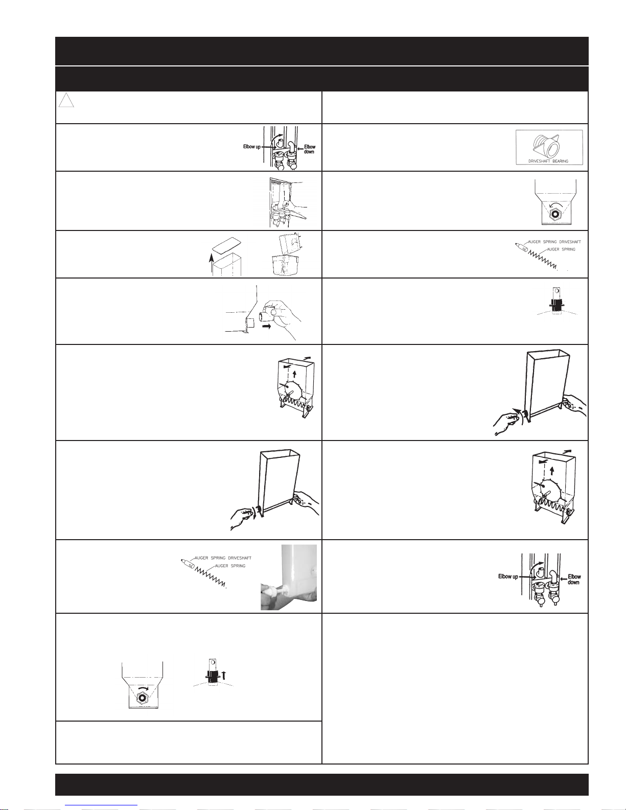
Weekly Cleaning (cont.)
Cleaning Hoppers - Disassembly Cleaning Hoppers - Reassembly
CAUTION: Do not wash hopper without first
disassembling.
IMPORTANT: All components must be completely dry
prior to reassembly.
Open door and rotate elbow on hopper
to the UP position to prevent spillage.
Place driveshaft bearing inside hopper
with threads going through the hole in
the rear of the hopper.
Remove the hopper from the cabinet.
Secure the bearing by attaching the palnut
to the bearing at the outside rear hopper
opening. Tighten using fingers only. Use one hand
inside the hopper to push the bearing outward while
turning the palnut counterclockwise.
Remove the hopper cover
and empty hopper
contents.
Install the auger spring driveshaft and
the auger spring by inserting the flat end
of the spring into the hole in the auger
spring driveshaft.
Pull off the elbow.
Insert assembly into lower front opening,
making sure the threaded end of the auger
spring driveshaft completely inserts into the
driveshaft bearing in the rear of the hopper.
Remove the auger pinwheel by pulling it
forward while stretching out the sides
of the hopper.
Place the washer over the
driveshaft bearing threads followed
by securing the drivelink onto the driveshaft bearing by turning counterclockwise. Secure the auger spring with one
hand while attaching the drivelink with
the other.
Remove the drivelink and washer at
the rear of the hopper by holding the
auger spring with one hand at the front of
the hopper while turning the drivelink
clockwise with the other hand.
Replace the auger pinwheel making sure the
pins are securely positioned inside the notches
under the hopper.
Remove the auger spring and auger spring
driveshaft by pulling out
through the lower front
opening of the hopper.
Turn the elbow DOWN toward the mixing
funnel. Stop when the elbow is at
the 7 o’clock position.
Remove the palnut at the rear of the hopper by turning it
clockwise then remove the driveshaft bearing from
the inside of the hopper.
All parts in contact with food must be washed, rinsed,
sanitized, and air dried.
!
1.
2.
3.
4.
5.
1.
2.
3.
4.
6.
9.
8.
7.
5.
6.
7.
PULL
Driveshaft
Bearing
PULL
Driveshaft
Bearing
Crathco Cold Powdered Beverage Dispensers Page 7
Page 8

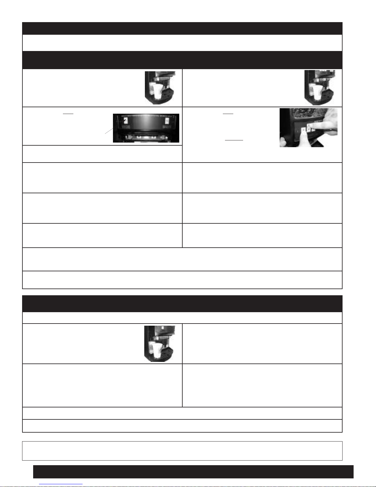
How to Dispense a Cup of Beverage
Models with Manual Dispense Switches
(Refer to serial tag to verify model number of your machine)
Place cup under the selected
1.
drink dispense nozzle.
Push and hold the appropriate
2.
switch on the touchpad until
cup is 2/3 full and then
release switch.
ispense Switch
D
NOTE: Portion may be cancelled by “push and release” of the switch during dispensing.
CAUTION: Cup must rest flat on tray with a 1/4” (6 mm) clearance between cup and spout.
Models with Portion Control
(Single portion or 3 portion per head)
Place cup under the selected
1.
drink dispense nozzle.
Push appropriate switch on
2.
the touchpad, then release
to dispense one preset serving.
(See Portion Control Adjustment
to set portion size)
ispense Switch
D
Changing the Merchandiser Lightbulb
WARNING: Disconnect machine from branch electrical supply before changing the lightbulb.
NOTE: The machine uses a F8T5 12” 8 watt replacement bulb.
Remove the front merchandiser photo
1.
and cover by grasping the edges of the
merchandiser.
Remove the old lightbulb by gently
2.
turning the lightbulb 1/4 turn to the left
and pulling the bulb from the socket.
Install the new bulb by lining up the pins
3.
on either end of the bulb parallel with the
socket opening.
Gently insert both ends of the bulb into
4.
the socket and turn the bulb 1/4 turn to
the right until the bulb locks into place.
Replace the merchandiser photo and
5.
cover.
Page 8 Crathco Cold Powdered Beverage Dispensers
Page 9
Portion Adjustment
If machine is a manual dispense, there are no portion control adjustments to be made. (Please refer to serial tag to
reference model number.
Setting Single Portion Control Setting Three Portion Sizes Per Head
Place a cup under the selected drink
1.
dispense nozzle.
Press and hold the dispense
2.
switch for 10 seconds.
ispense Switch
D
After a 10 second time delay, the machine is triggered into
3.
program mode and will begin dispensing.
Continue pressing the button until cup is approximately
4.
2/3 full, then release the switch to prevent overfill. The
elapsed portion dispense time is saved to memory and
will remain until the dispense switch is reprogrammed.
Check the portion size by placing an empty cup under the
5.
desired dispense nozzle, the press and release the
dispense switch. The machine will dispense the
preprogrammed portion size.
If the portion size is incorrect, repeat above steps until the
6.
desired portion size is achieved. Each dispense switch
needs to be set separately.
Place a cup under the selected drink
1.
dispense nozzle.
Press and hold one of the size
2.
buttons (S, M or L) on the touch
pad. (Hold button throughout entire
procedure).
Then press and release
(top-off) button ( ) . After 10 seconds,
while still depressing portion button, programming sequence
will start.
Continue pressing the size button until cup is approxi-
3.
mately 2/3 full, then release the switch to prevent overfill.
The elapsed portion dispense time is saved to memory
and will remain until the dispense switch is reprogrammed.
Check the portion size by placing an empty cup under the
4.
desired dispense nozzle, then press and release the
dispense switch. The machine will dispense the
preprogrammed portion size.
If the portion size is incorrect, repeat above steps until the
5.
desired portion size is achieved. Each portion size for
each head needs to be set separately.
*
the manual
CAUTION: After button release, there will be 50 ml (1.7 fl. oz.) of water added to the cup. Each dispense includes a 1 second
delay for powder at start and 1 second run-on for water and whipper at end of dispense. This allows for extra rinsing inside the
whipper chamber.
NOTE: Each “S” button on touch pad is pre-set to dispense 150 ml (5 fl. oz.) of water. “M” and “L” settings are not pre-set for
any specified volume unless requested.
Drink Strength Adjustment
Tools Required: Small, Flat Screwdriver
Dispense a drink to determine if drink is
1.
too strong or too weak.
Remove drip tray. Dispense a drink to determine if drink strength is
2.
NOTE: Clockwise rotation will result in a stronger drink and counterclockwise will result in a weaker drink.
NOTE: Water flow rate is factory preset at approximately 24 mL (0.80 ounces) per second.
Using a flat head screwdriver, adjust individual dispense
3.
heads by rotating appropriate adjustment knob.
Clockwise rotation will result in a stronger drink and
counterclockwise will result in a weaker drink.
4.
acceptable, repeat adjustment steps until desired drink
strength is achieved.
NOTE: Machines are factory set in cooling mode to control drinking water temperature between 2.2°C (36°F) and
5.5°C (42°F) and it cannot be adjusted.
Crathco Cold Powdered Beverage Dispensers Page 9
Page 10
Prepare for Shipment
Important: Always completely empty ice bank water tank and POWDER HOPPERS prior to shipping unit. (See
Draining the Tank and Cleaning the Hoppers section).
NEVER SHIP UNIT WITH POWDER IN HOPPER OR WATER IN TANK - THIS MAY CAUSE
IRREPARABLE DAMAGE.
Draining the Tank
Always empty the tank before shipping.
WARNING: Draining of the tank should be performed by a qualified service technician.
!
NOTE: CP3 ice bank tank contains 7.5 L (2 gallons) of water if no ice is present in the tank.
Prepare a container to drain the
1.
tank water into. The container
must hold at least 10 L
(2.6 gallons).
Remove right side louver panel. Drain hose is right behind
2.
the panel routed down and then up to lean against back
wall - The hose is insulated.
Locate the silicone drain hose
3.
end. Put the end of the drain
hose into the container.
Allow the tank to drain completely.
5.
NOTE: It is likely that there will be approximately 4.5 lb
(2 kg) of ice around the evaporator. This ice needs to be
melted and the water drained from the machine:
a) Plug the drain hose
b) Power up the machine
c) Allow to fill the tank.
d) When the compressor starts (fan blade will turn)
turn the machine OFF.
e) Drain the tank.
f) Repeat this cycle three times beginning step (a).
To drain remaining water from
6.
the bottom of the tank, tilt the
dispenser 30° to the right. Once
the tank is empty, securely
replace the plug and
clamp on the end of the hose.
Reposition the drain hose inside
the hose clip.
Replace the louver panel.
7.
Pinch hose with fingers and remove the hose clamp
4.
and plug.
Page 10 Crathco Cold Powdered Beverage Dispensers
Page 11
Refrigeration System Maintenance
Ice Bank Tank Cleaning
NOTE: This procedure may need to be performed once every other year depending on water quality.
If time to make the ice bank or recover the ice bank from the dispensing period is becoming excessively long (e.g. twice as long
as it should take compared to the experience noted in the same ambient conditions) it is likely that there is too much mineral
deposit on the evaporator coil and/or the heat exchanger. The layer of minerals insulates the coil from the water or ice therefore
cooling time increases. To correct the problem, the ice bank tank assembly needs to be cleaned. Proceed as follows:
Turn the power OFF and unplug the machine from the
1.
power receptacle.
Drain the tank (see instructions on page 5). Drain the ice bank tank (see instructions on page 5).
2.
Remove agitator motor from the ice bank tank and clean
3.
any visible mineral deposits from the motor shaft, bottom
of the motor and the propeller.
Through the opening in the lid of the ice bank, add to the
4.
tank a mixture of 1 liter (34 fl. oz.) of distilled vinegar
(clear) and 5 liters (1.3 gallons) of lukewarm water.
Replace the agitator motor.
Disconnect water inlet valve. (Pull the brown wire).
Valve is located on the left side of the machine at the
back.
Turn the machine ON. Replace side panel. The tank and the coils now should
5.
Run the machine for 15 minutes. Turn the machine ON.
6.
Turn the machine OFF.
7.
8.
When water will stop flowing tilt the machine to the right
about 30° to remove remaining water.
Reconnect water inlet valve (brown wire).
Plug the drain hose and start the machine.
9.
When the compressor starts, turn the machine OFF
10.
and repeat this process beginning with step #8 twice.
11.
be free of mineral deposits.
12.
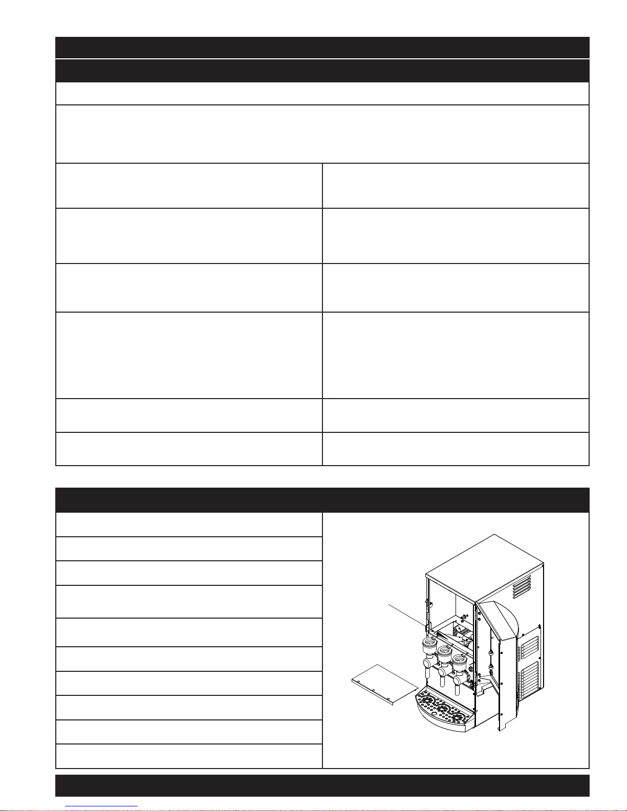
Remove the service panel located under the hoppers.
1.
Remove the dark gray foam filter from plenum.
2.
Bring the filter under running water.
3.
Under the running water, squeeze the filter a couple of
4.
times, by hand, to wash the powder from it.
Squeeze the filter one more time to remove the water
5.
from the foam.
Shake the filter vigorously a couple of times to dry it.
6.
Roll the foam sheet as a tube 1” (25.4 mm) diameter.
7.
Insert the foam into the plenum.
8.
Replace the service access panel.
9.
Install the hopper back into the machine.
10.
Crathco Cold Powdered Beverage Dispensers Page 11
Filter Cleaning
Filter location
Page 12

CP3 Preventative Maintenance Checklist (Every 6 to 12 months)
A preventative maintenance visit should be performed every 6 to 12 months, depending on usage. The following procedures should be
performed during a preventative maintenance visit.
Parts Required: One PM parts kit (Part # 60933).
Tools Required: 11/32 nut driver, needle nose pliers, phillips head screwdriver, food grade lubricant.
The following procedures should be performed by a qualified service technician.
!
WARNING - Risk of electric shock. Disconnect power before servicing.
1. Document model and serial number of equipment above.
2. Disconnect unit from power supply and turn power switch off. Then remove all access panels.
3. Shut off the water supply valve to the machine.
4. Open front door of unit and remove product hoppers. Clean hoppers following procedures on the decal on panel behind
hoppers or as stated in instruction manual.
5. Remove the plenum chamber access panel and filter. Wipe out exposed plenum.
6. Locate the tank drain hose. It is located behind the right side access panel. It is a white silicone tubing that has a 3/8” stainless
steel barb plug and a black 5/8” hose clamp on it.
7. Prepare a container to drain the tank water into. Locate the silicone drain hose on the left side wall. Put the end of the drain
hose into the container. Secure the end of the drain hose
(i.e. with tape) into the container. Pinch hose with fingers and remove the hose clamp and plug. Allow tank to drain completely.
Note: It may be necessary to pinch the hose and stop the water before container is full. Carefully re-install plug, then empty
container. Repeat process until tank is drained completely. Once the tank is empty, securely replace the plug and clamp on the
end of the hose. Refer to Draining the Tank section on page 5.
8. Remove the mixing funnel shroud and mixing funnel from each chamber. Remove and discard the o-ring on the mixing funnel.
Set the shroud and funnel aside.
9. Remove each whipper chamber and whipper blade and discard. Then remove and discard the small whipper shaft o-rings from
each dispense head.
10. Remove the two screws from each whipper base and save the screws. Clean the whipper motor shaft and clean all dried
product in this area under where the whipper base was located. Discard the old whipper base and slinger washer, and
replace with the new parts in the PM kit.
11. Install the new slinger washer onto the whipper motor shaft.
12. Lubricate inside of whipper base with a food grade lubricant. Then install whipper base over the whipper motor shaft and
tighten mounting screws.
13. Check whipper motor shaft to ensure it can turn freely using fingers. If shaft is hard to turn, remove screws, rotate base
180°, and then re-tighten the mounting screws. If the motor shaft is still hard to turn, replace the motor.
14. Install the new, red, small o-rings, along with the new whipper blades, and new whipper chambers. Clean the funnel shrouds
and funnels. Install the new funnel o-ring and lubricate. Install funnel and shroud.
15. Remove plenum through side access opening and remove the plenum hose(s) from the blower to the plenum chamber. Clean
the plenum and either clean or replace the hose. Clean the air filter (see instructions on page 6). If the blower fan is clogged
with powder product clean it by taking apart the blower shroud and blower blade. Re-install clean parts.
16. Turn on water supply, and verify adequate water flow.
17. Plug the power cord back into outlet. Turn main power switch to “on”.
18. Verify water tank is filling. .
19. Allow unit to fill and shut off. Check around valves and any tubing for signs of water leaks. Verify the cooling cycle has started
20. Replace all access panels and reinstall hoppers inside the unit. Verify nut on back of hopper is secure.
21. Verify each dispense head is operating properly and that the settings are correct. Adjust if necessary.
22. Check for proper product temperature and check mix ratio for proper setting, and adjust if necessary.
23. Review proper care, cleaning and maintenance procedures with store personnel.
Page 12 Crathco Cold Powdered Beverage Dispensers
Page 13

Troubleshooting Guide
Only a qualified service technician should perform electrical and mechanical adjustments or repairs.
Always disconnect power before attempting any maintenance procedures.
PROBLEM PROBABLE CAUSE CORRECTIVE ACTION
Powder is not dispensing • Rinse switch turned to “RINSE ON” position
Machine is not dispensing • Power turned “OFF” to machine
Product not whipping • Whipper blade broken or missing
Water overflows mixing funnel • Water flow too fast
Drink is too weak or strong Refer to Drink Strength Adjustment section (page 4)
No cold water from
dispense head
REFRIGERATION TROUBLESHOOTING
Compressor will not start • No power
Compressor will not start hums but trips on overload
Compressor starts but start
relay does not switch off.
Compressor starts but short
cycles on overload protector
Unit operates long or
continuously
• Powder hopper dispense outlet clogged
• No or low powder level in hopper
• Hopper drivelink not engaged with motor
• Hopper elbow is not directed into the mixing funnel
• Dispense cycle watchdog timer has tripped
• Faulty transformer
• Faulty control board
• Faulty whipper motor speed control
• Faulty whipper motor
• Whipper chamber outlet restricted
• Whipper blade broken or missing
• Water level in tank is below water probe
• Faulty compressor relay
• Tube from dispensing valve is kinked
• Water shorting out probe connections
• Faulty Ice Bank Agitator Motor (ice bank frozen)
• Faulty dispensing triple valve
• Compressor power relay failed (located on
controller board)
• Controller board or water inlet valve failure
• Wiring improper/loose
• Compressor improperly wired
• Low voltage to the unit
• Compressor relay failing to close
• Compressor failure
• Improperly wired
• Low voltage to unit
• Relay failing to open
• Low voltage to the unit
• Overload protector defective
• Excessive discharge pressure
• Compressor is too hot, return gas line (suction is hot)
• Compressor motor has windings shorted
• Frequent dispensing cycle
• Dirty condenser
• Unit is low on refrigerant
• Flip rinse switch to “RINSE OFF” position
• Clean hoppers
• Refill hoppers
• Remove and reinstall hopper. Ensure engagement
with motor
• Turn down dispense elbow; align with mixing funnel
• Ensure power switch is in “ON” position, machine is
plugged in and water is turned on
• Reset machine by flipping power switch “OFF” then “ON”
once
• Contact factory for assistance with faulty components
• Verify blade is in place. Replace if broken or missing
• Reset speed control. If cannot reset speed control replace it.
• Contact factory for assistance
• Remove obstruction in mixing chamber or nozzle
• Verify blade is in place. Replace if broken or missing
• Ensure water supply is on to machine and reset power
• Replace relay
• Check tubing for obstructions
• Dry connections on tank
• Thaw out ice bank, replace the motor
• Replace the valve
• Trace power input
• Replace relay
• Check power light is ON
Check if ice bank has sufficient water level (compressor
will not start unless ice bank has correct water level)
• Check wiring against wiring diagram (compressor
electrical box, water inlet valve or compressor power relay)
• Check wiring in compressor electrical box
• Determine reason and correct
• Replace relay (compressor electrical box)
• Replace compressor
• Correct wiring
• Determine reason and correct
• Replace relay
• Determine reason and correct
• Replace overload protector
• Check air flow across condenser (dirty condenser),
restrictions in the refrigeration system
• Check for leaks, low charge
• Replace compressor
• Normal operation
• Clean condenser (removecondenser fan shroud and rear
panel)
• Check for refrigerant leaks and repair then recharge unit.
Suction line frosted • Refrigerant charge too high • Correct the charge (169 grams or 5.91 ounces of R134a)
Liquid line frosted or sweating • Restriction in filter drier (dehydrator)
(more likely end of capillary tube)
If you still need help, call our service department at (800) 695-4500 (USA & Canada only) or (502) 425-4776 Monday - Friday, 8 am - 6 pm EST) or an authorized
service center in your area. Please have the model and serial numbers ready so that accurate information may be given.
Prior authorization must be obtained from Grindmaster Corporation’s Technical Services Department for all warranty claims.
Crathco Cold Powdered Beverage Dispensers Page 13
• Replace the filter drier
Page 14

Replaceable Parts
Part # Description Part # Description
PIC 3 Cold
120V/60z
PIC 3E Cold
230V/50z
PIC 3 Cold
120V/60z
PIC 3E Cold
230V/50z
61490 61490 62395 62395
ssy, Hopper 5#, Auger .718
A
Sugarbased, 2 pinwheel
62925 62925 61221 61221
Assy, Hopper 5#, Auger .406
non-sugar, 2 pinwheel
61442 61442 61127 61127
Assy, Hopper 5#, Auger .718
ugarbased, 1 pinwheel
S
62926 62926 60741 60741
Assy, Hopper 5#, Auger .406
non-sugar, 1 pinwheel
Chamber, Whipper
Funnel, Whipper Mixing
-Ring, Funnel
O
O-RIng, Whipper Shaft
61302 61302 65014 65014
Spring, Auger .718 Pitch
Sugarbased Product
61278 61278 61539 61539
Spring, Auger .406 Pitch
Non-sugar Product
61223 61223 100174 100175
Elbow, 3/4 x 3/4 Hopper
61523 61523 61118 61118
Whipper Base Assembly
61458 61458 05096 70271
Controller
Remote Board
100174
Compressor
Lamp, Fluorescent F8T5 8 Watts
100175
Blade, Whipper (4 Blade)
Page 14 Crathco Cold Powdered Beverage Dispensers
Lamp, Red
Page 15

Replaceable Parts
Part # Description Part # Description
PIC 3 Cold
120V/60z
PIC 3E Cold
230V/50z
PIC 3 Cold
120V/60z
PIC 3E Cold
230V/50z
62436 61125 61847 61466
ight, Indicator Green
L
61103 61111 61847 61847
Motor, Fan
65045 65045 62432 62432
Motor Gear, Auger Dispenser
20 rpm for Sugarbased Product
2
65057 65057 62415 62415
Motor Gear, Auger Dispenser
30 rpm for Non-sugar Product
61847
Switch, Power
Switch, Rinse
ouch Pad - Single Portion
T
Touch Pad - Three Portions
61466
61116-01 61117-01 61481 61470
Motor, Whipper
61131 61131 61198 61198
Relay
61194 61194 61892 61892
Starter, FS-5
61196 61468 65062 65020
Ballast
65399
Kraft
restrictor
65399
Kraft
restrictor
65066 65034
61481
Transformer
Tray, Drain
Grid, Drain
Valve Dispensing, Triple Outlet
Valve Inlet, Dual Outlet
61470
Crathco Cold Powdered Beverage Dispensers Page 15
Page 16

Controller Information
Jumper settings
The controller has (5) 3-pin jumpers along side
the left hand side of the controller. The top pin is
number one, the center is number two and the
bottom pin is number three.
See Figure 1
1
O
2
O
3
Cleaning indicator
The J6 jumper is in on the upper left hand corner J6
This controls the cleaning or rinse reminder LED on the front touch
pad. If the jumper is between terminal 1 and 2 the reminder LED is
enabled. If the jumper is between the 2 and 3 terminal the reminder
LED is off. The timing sequence is every 23 hours the reminder will
illuminate the led. To reset: turn the unit to the rinse mode and rinse
each flavor. This will then reset the timer for the next 23 hour
period.
Dispense Function configuration
The J1 jumper is on the left hand side towards the center J1
This is the dispense function configuration. The default is between
pin 1 and 2 (automatic mode) Do not place the pin between the 2
and 3 pin as the unit will not function.
Cleaning indicator reset – Rinse switch reset circuit
The J2 jumper is just below the J1 on the left side center
This has a connector that hold two wires that goes to the rinse
switch. When the rinse switch is turned on, terminals 2 and 3 are
jumped together resetting the cleaning LED.
Speed Control Configuration
The lower left hand side contains three jumpers
These three jumpers will set the controller to
recognize the onboard auger speed controllers.
Set the jumper between 2 and 3 pin for onboard control (shown)
Set the jumper between 1 and 2 pin for remote controllers (front
panel)
Page 16 Crathco Cold Powdered Beverage Dispensers
Figure 1
J2
J5 left
J4 middle
J3 right
Auger speed controllers
These control the speed of the DC auger motors
Page 17

CP-3 Refrigeration System Part Numbers
Filter Drier (65013) Compressor 115 V (100174)
Condenser Shroud (100169)
Condenser Fan (65064) Condenser (100168)
Refrigeration System information;
Refrigerant R-134A Amount 169 Grams (5.91 Ounces)
The refrigeration system builds and maintains a thickness of ice inside and at the bottom of the water tank. The remaining tank
water is in constant motion via the agitator propeller. The dispensing water travels through a heat exchanger coil also inside the
water tank. Therefore the dispensing water is not in direct contact with the tank water but travels through it and is chilled to the
desired temperature. The water level inside the tank is maintained by the control board to a preset level. The refrigeration system
Is sealed and the system is charged with a very precise amount of refrigerant. No gauge access is provided.
C
Crathco Cold Beverage Dispensers
Page 17
Page 18

CP3 Ice Bank Assembly
Page 18 Crathco Cold Powdered Beverage Dispensers
Page 19

CP3 Lower Panel Assembly
Crathco Cold Powdered Beverage Dispensers Page 19
Page 20

CP3 Condenser Assembly
Page 20 Crathco Cold Powdered Beverage Dispensers
Page 21

CP3 Agitator Motor Assembly
Crathco Cold Powdered Beverage Dispensers Page 21
Page 22

CP3 Controller Panel
Page 22 Crathco Cold Powdered Beverage Dispensers
Page 23

CP3 Hopper Shelf Assembly - 120V
65045
65057
Crathco Cold Powdered Beverage Dispensers Page 23
Page 24

CP3 Hopper Shelf Assembly - 220V
Page 24 Crathco Cold Powdered Beverage Dispensers
Page 25

CP3 Hopper Assembly
Crathco Cold Powdered Beverage Dispensers Page 25
Page 26

CP-3 Controller
P-
Controller part number 65014
Page 26 Crathco Cold Powdered Beverage Dispensers
Page 27

CP3 Drink Strength & Portion Control Adjustment
CP3 Auger Speed Adjustment
Crathco Cold Powdered Beverage Dispensers Page 27
Page 28

CP3 Hot Flush Final Assembly
Page 28 Crathco Cold Powdered Beverage Dispensers
Page 29

CP3 Hot Flush Assembly
Crathco Cold Powdered Beverage Dispensers Page 29
Page 30

CP3 Hot Flush Tank Assembly
Page 30 Crathco Cold Powdered Beverage Dispensers
Page 31

CP3 Hot Flush Shelf Assembly
Crathco Cold Powdered Beverage Dispensers Page 31
Page 32

CP-3 Refrigeration and Water System
Page 32
Crathco Cold Powered Beverage Dispensers
Page 33

CP-3 Door Assembly - single portion
Crathco Cold Powdered Beverage Dispensers
Page 33
Page 34

CP-3 Door assembly - three portion
r
Page 34
Crathco Cold Powdered Beverage Dispense
Page 35

CP-3 Wiring Diagram 120 VAC
Crathco Cold Powdered Beverage Dispensers Page 35
Page 36

CP-3 Pictorial Wiring Diagram 120 VAC
Page 36 Crathco Cold Powdered Beverage Dispensers
Page 37

CP-3AE Wiring Diagram with all options shown
Crathco Cold Powdered Beverage Dispenser Page 37
Page 38

Notes and Comment page
Page 38 Crathco Cold Beverage Dispenser
Page 39

Page 40

© Grindmaster Corporation, 2003
PRINTED IN USA
0405 Form # CC-352-01
Part #
Grindmaster® Coffee Grinders and Brewers • Espressimo® Espresso Machines • Crathco® Hot Beverage Dispensers
Crathco® Cold and Frozen Beverage Dispensers • American Metal Ware® Coffee and Tea Systems
Tel (502) 425-4776 • Fax (502) 425-4664 • 1-800-695-4500 (USA & Canada only)
P.O. Box 35020 • Louisville, KY 40232 • USA
www.grindmaster.com • email: info@grindmaster.com
 Loading...