


Green Power Semiconductors GC89SRDE15F, GC89SRDE12FS, GC89SRDE12F, GC89SRDE10FS, GC89SRDE10F Datasheet
...
GC89…F
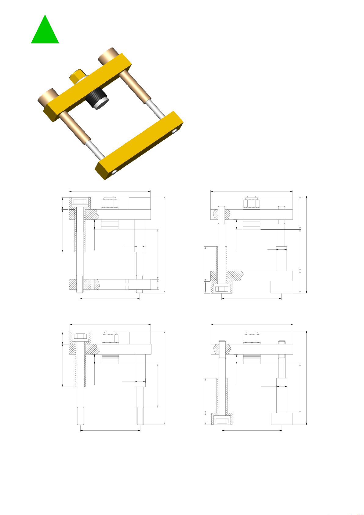
BAR CLAMP FOR HOCKEY PUKS
Various lenghts of bolts and insulators
Pre-loaded to the specific clamping force
Flat clamping head for minimum
clamping head height
Four clamps styles
Gold iridite plating
User friendly clamping force indicator
UL94 certified insulation material
Dimensions in millimeters
T:
Max total height (see table)
S:
Clearance allowed ( see table)
Document GC89…FT001
GPS - Green Power Semiconductors SPA
Factory: Via Ungaretti 10, 16157 Genova, Italy
Phone: +39-010-667 8800
Fax: +39-010-667 8812
Web: www.gpsemi.it
E-mail: info@gpsemi.it
Green Power
Semic onduct ors
T
115
S
20
14
50 up to 120
89
12
89
12
T
115
50 up to 120
14
S
34
12
89
115
50 up to 120
14
T
S
115
T
S
89
14
50 up to 120
12
GC89BN...F GC89BR...F
GC89SR...FGC89SN...F
54
19.4±0.2
19.4±0.2
19.4±0.2
19.4±0.2
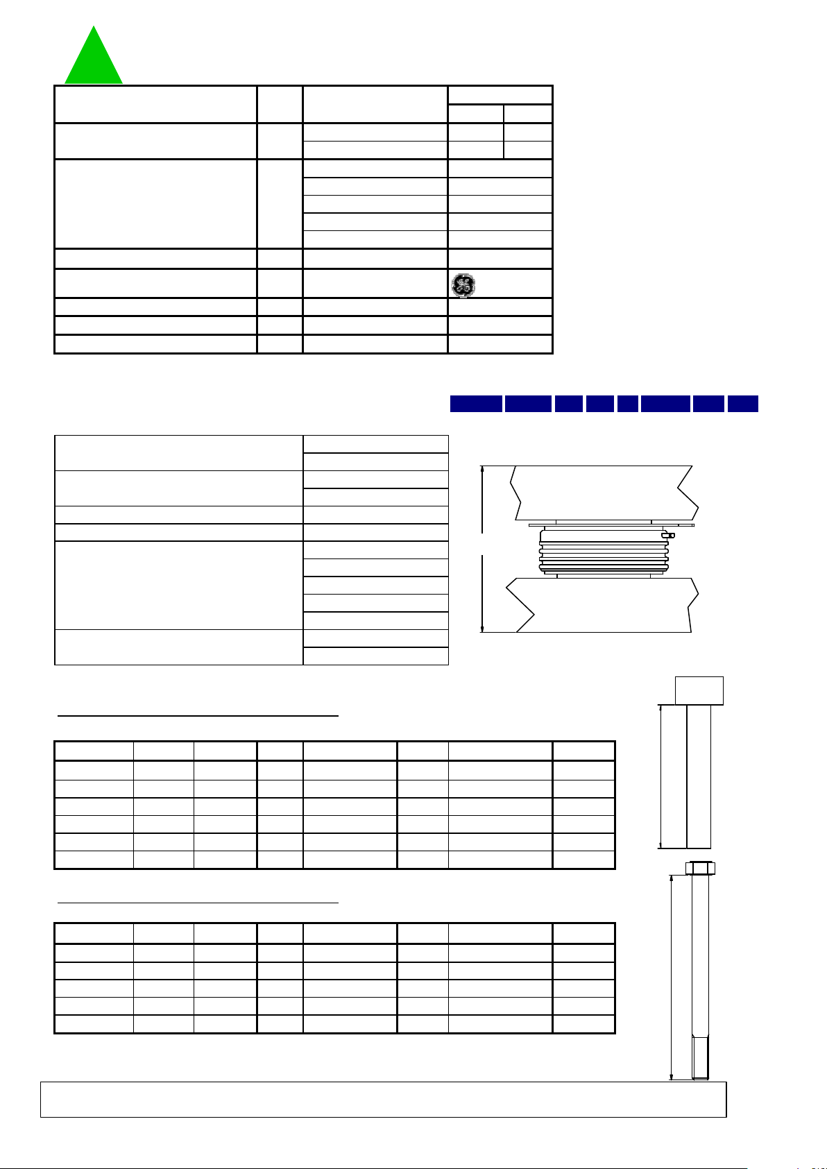
BAR CLAMP FOR HOCKEY PUKS GC89…F
Min Max
GC89S…F 590 720
GC89B…F 980 1150
GC89…08F
GC89…10F
GC89…12F
GC89…15F
GC89…20F
V
RMS
1 min
UL File: E121562
°C
°C
°C
* Other clamping forces available: contact factory
ORDERING INFORMATION TABLE
Clamps can be ordered using the following part numbering system GC89 B N A B 20 F S
(1) (2) (3) (4) (5) (6)
(1) Construction type:
(2) Insulator position:
(3) Insulator code:
(4) Bolt code:
(5) Clamping force (in kN):
(6) Special accessories
K: Total thickness of the assembly to be clamped
For thicknesses S'
Min
< K < S
Min
an additional 4 mm thick
metal spacer is needed ( see list of special accessories)
Type GC89BN…F: suggested insulator/bolt types
S' Min[mm]** S Min [mm] SMax [mm] (3) Ins. Lenght [mm] Bolt Lenght [mm]
39 43 50 A/B 50/70
49 53 60 B 70
59 63 70 B/C 70/95
69 73 80 C 95
79 83 90 C/D 95/120
89 93 100 D 120
** with additional metal spacer only
Type GC89BR…F: suggested insulator/bolt types
S' Min[mm]** S Min [mm] SMax [mm] (3) Ins. Lenght [mm] Bolt Lenght [mm]
39 43 50 A/B 50/70
49 53 60 B 70
59 63 70 B/C 70/95
69 73 80 C 95
79 83 90 C/D 95/120
** with additional metal spacer only
Document GC89…FT001
169
179
T [mm]
139
149
159
157
167
177
Max height
T [mm]
127
137
147
150
160
110
120
110
120
130
140
140
(4)
A
E
B
C
D
150
130
Allowed clearance S Insulator choice Bolt choice
(4)
A
E
F
B
C
D
Allowed clearance S Insulator choice Bolt choice
Max height
10
12
20
blank = no accessories
S = extra metal spacer
15
Storage temp. -40/110
B = with double bar
S = with single bar
Max. working temperature 110
Min. working temperature -30
Clamping Force* kN
8
10
12
15
Insulation Voltage 3000
Insulating Material Noryl
Weight
Types/Testing
conditions/Notes
UnitParameter
Values
g
20
N = upper side
R = lower side
see table below
see table below
08
Green Power
Semiconductors
K
3
4
K
In the interest of product improvement Green Power Semiconductors reserves the right to change any specification given in this data
sheet without notice.
 Loading...