


Green Power Semiconductors GC70SN9515020RD, GC70SN9515020R, GC70SN9515015RS, GC70SN9515015RD, GC70SN9515015R Datasheet
...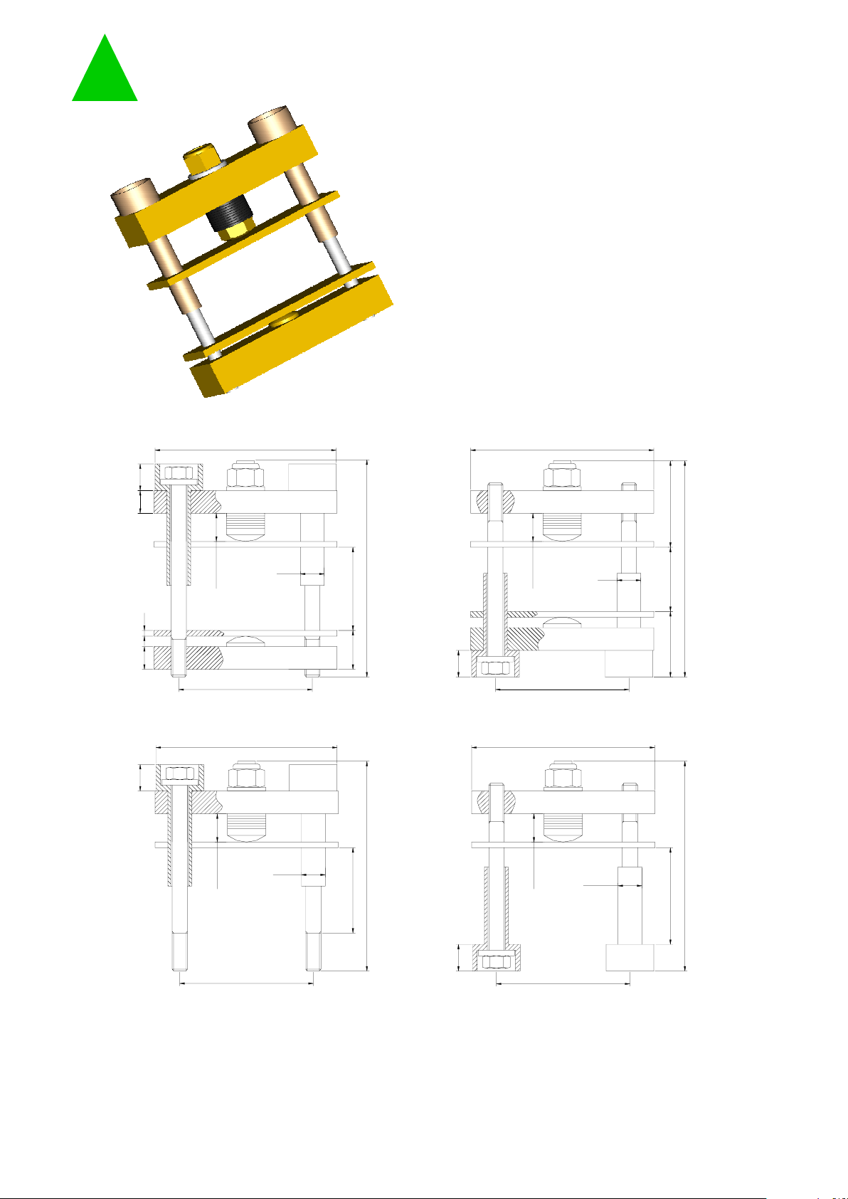
GC70…R
BAR CLAMP FOR HOCKEY PUKS
Various lenghts of bolts and insulators
Round shaped clamping head for optimal
Pre-loaded to the specific clamping force
Four clamps styles
Gold iridite plating
User friendly clamping force indicator
UL94 certified insulation material
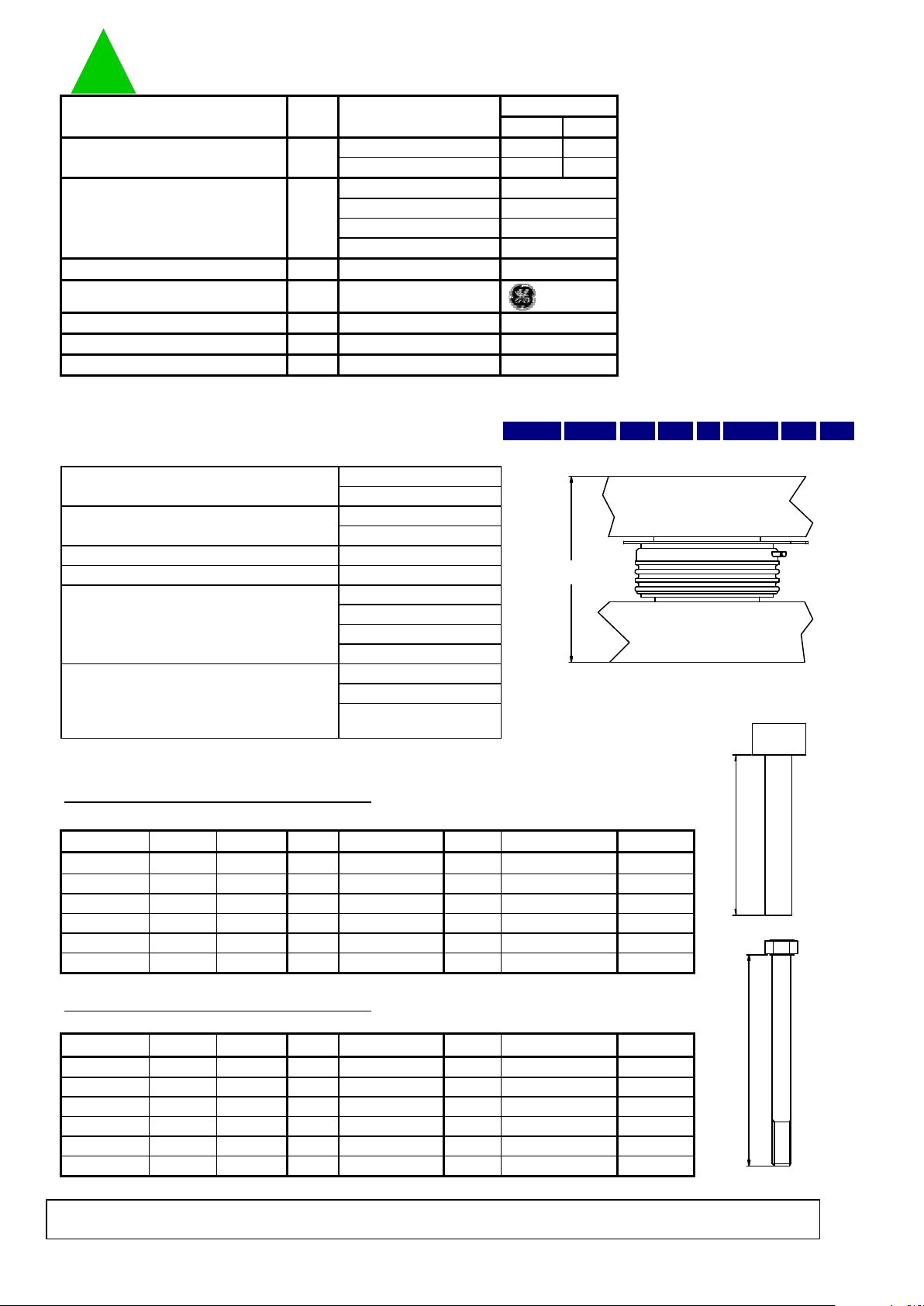
Dimensions in millimeters
T:
Max total height (see table)
S:
Clearance allowed (see table)
Document GC70…RT001
clamping force application
GPS - Green Power Semiconductors SPA
Factory: Via Ungaretti 10, 16157 Genova, Italy
Phone: +39-010-667 8800
Fax: +39-010-667 8812
Web: www.gpsemi.it
E-mail: info@gpsemi.it
Green Power
Semic onduct ors
T
95
S
21
14
70
12
70
12
T
95
14
S35
12
70
95
14
T
S
95
T
S
70
14
12
GC70BN...R GC70BR...R
GC70SR...RGC70SN...R
12
12 4
18.4±0.2
18.4±0.2
18.4±0.2
18.4±0.2
48
BAR CLAMP FOR HOCKEY PUKS GC70…R
Min Max
GC70S… 420 520
GC70B… 590 730
GC70…12
GC70…15
GC70…20
GC70…22
V
RMS
1 min
UL File: E121562
°C
°C
°C
* Other clamping forces available: contact factory
ORDERING INFORMATION TABLE
Clamps can be ordered using the following part numbering system GC70 B N A B 20 R S
(1) (2) (3) (4) (5) (6)
(1) Construction type:
(2) Insulator position:
(3) Insulator code:
(4) Bolt code:
(5) Clamping force (in kN):
(6) Special accessories
K: Total thickness of the assembly to be clamped
For thicknesses S'
Min
< K < S
Min
an additional 4 mm thick
metal spacer is needed ( see list of special accessories)
Type GC70BN…: suggested insulator/bolt types
S' Min[mm]** S Min [mm] SMax [mm] (3) Ins. Lenght [mm] Bolt Lenght [mm]
35 39 46 B 70
45 49 56 B 70
55 59 66 B/C 70/95**
65 69 76 C 95
75 79 86 C 95
85 89 96 D 120
** with additional metal spacer only
Type GC70BR…: suggested insulator/bolt types
S' Min[mm]** S Min [mm] SMax [mm] (3) Ins. Lenght [mm] Bolt Lenght [mm]
35 39 46 A 50
45 49 56 A/B 50/70*
55 59 66 B 70
65 69 76 B 70
75 79 86 C 95
85 89 96 C 95
** with additional metal spacer only
Document GC70…RT001
145
155
165
175
162
172
125
135
122
132
142
152
150
T [mm]
Max height
T [mm]
150
160
110
120
110
120
130
140
140
(4)
A
160
130
E
Allowed clearance S Insulator choice Bolt choice
F
B
C
D
(4)
A
E
F
B
C
D
Allowed clearance S Insulator choice Bolt choice Max height
12
15
20
D = pressure disc in place
of pressure bar
22
blank = no accessories
S = extra metal spacer
N = upper side
R = lower side
see table below
see table below
Storage temperature -40/110
B = with double bar
S = with single bar
Max. working temperature 110
Min. working temperature -30
22
Insulation Voltage 3000
Insulating Material Noryl
Clamping Force* kN
12
15
20
Values
gWeight
Types/Testing
conditions/Notes
UnitParameter
Green Power
Semiconductors
In the interest of product improvement Green Power Semiconductors reserves the right to change any specification given in this data
sheet without notice.
K
3
4
K
 Loading...