


Green Power Semiconductors GC89SRCF27RS, GC89SRCF27RD, GC89SRCF27R, GC89SRCF24RS, GC89SRCF24RD Datasheet
...
Green Power Solutions srl |
Phone: +39-010-659 1869 |
|
Fax: +39-010-659 1870 |
||
Via Greto di Cornigliano 6R - 16152 Genova , Italy |
||
Web: www.gpsemi.it |
||
|
||
|
E-mail: info@gpsemi.it |
GC89…R
BAR CLAMP FOR HOCKEY PUK DEVICES
Clamping total thikness of assembly from 11mm to 119mm
Pre-loaded to the specific clamping force (12 ÷ 24 kN)
Maximum device diameter: 76mm
Surface passivation to provide extra protection Hexagon head bolt partially
threaded M8x1.25, UNI5737, 8.8 steel Various lengths of bolts and insulators
Round shaped clamping head for optimal clamping force application
Four styles available
User friendly clamping force indicator UL94 certified insulation material
Parameter |
Unit |
Types |
Testing conditions |
Notes |
|
Values |
|
|
|
Min |
Typ |
Max |
|||
|
|
|
|
|
|||
Weight |
g |
GC89S…R |
|
|
730 |
|
860 |
GC89B…R |
|
|
1120 |
|
1290 |
||
|
|
|
|
|
|||
|
|
GC89…12R |
|
|
|
12 |
|
Clamping Force* |
kN |
GC89…16R |
|
|
|
16 |
|
GC89…20R |
|
|
|
20 |
|
||
|
|
|
|
|
|
||
|
|
GC89…24R |
|
|
|
24 |
|
Clamping Force tolerance |
|
|
|
|
|
± 10% |
|
Insulation Voltage |
VRMS |
|
1 min |
|
|
3000 |
|
Insulating Material |
|
|
|
Noryl |
|
|
|
UL File |
|
|
|
E121562 |
|
|
|
Max. working temperature |
°C |
|
|
|
-30 |
|
110 |
Creepage distance: |
mm |
|
|
|
|
28 |
|
Clearance distance: |
mm |
|
|
|
|
20.3 |
|
Storage temperature |
°C |
|
|
|
-40 |
|
110 |
|
mm |
|
|
UL94 V-1 Flame class rating |
|
1.5 |
|
Flammability |
mm |
|
|
UL94 V-0 Flame class rating |
|
8.00 |
|
|
mm |
|
|
CSA Flammability |
|
1.00 |
|
*Other clamping forces available: contact factory
** Noryl is a registered trade mark of General Electric
Document GC89…RT001
|
|
BAR CLAMP FOR HOCKEY PUK DEVICES |
|
|
|
GC89…R |
|
|
|
|||||||||||||||||||
ORDERING INFORMATION TABLE |
|
|
|
|
|
|
|
|
|
|
|
|
|
|
|
|
|
|
|
|
|
|
|
|
|
|
|
|
|
|
|
|
|
|
|
|
|
|
|
|
|
|
|
|
|
|
|
|
|
|
|
|
|
|
|
|
|
Clamps can be ordered using the following part numbering system |
GC89 |
|
|
B |
|
N |
|
B |
|
A |
|
20 |
|
|
R |
|
|
S |
|
|
||||||||
|
|
|
|
|
|
|
|
|
|
|
|
|
|
|
|
|
|
|
|
|
|
|
|
|
|
|
|
|
|
|
|
|
(1) |
|
(2) |
(3) |
(4) |
(5) |
|
|
|
|
|
|
|
(6) |
|
|
|||||||||
|
|
|
|
|
|
|
|
|
|
|
|
|
|
|
|
|
|
|
|
|
|
|
|
|
|
|
|
|
(1) |
Construction type: |
B = with double bar |
|
|
|
|
|
|
|
|
|
|
|
|
|
|
|
|
|
|
|
|
|
|
|
|
|
|
|
|
|
|
|
|
|
|
|
|
|
|
|
|
|
|
|
|
|
|
|
|
|
|
|
|
|||
|
|
S = with single bar |
|
|
|
|
|
|
|
|
|
|
|
|
|
|
|
|
|
|
|
|
|
|
|
|
|
|
(2) |
Insulator position: |
N = upper side |
|
|
|
|
|
|
|
|
|
|
|
|
|
|
|
|
|
|
|
|
|
|
|
|
|
|
|
|
R = lower side |
|
|
|
|
|
|
|
|
|
|
|
|
|
|
|
|
|
|
|
|
|
|
|
|
|
|
|
|
|
|
|
|
|
|
|
|
|
|
|
|
|
|
|
|
|
|
|
|
|
|
|
|
|
|
|
|
|
|
|
|
|
|
|
|
|
|
|
|
|
|
|
|
|
|
|
|
|
|
|
|
|
|
|
|
(3) |
Insulator code: |
see table below |
|
|
|
|
|
|
|
|
|
|
|
|
|
|
|
|
|
|
|
|
|
|
|
|
|
|
|
|
|
|
|
|
|
|
|
|
|
|
|
|
|
|
|
|
|
|
|
|
|
|
|
|
|||
|
|
|
|
K |
|
|
|
|
|
|
|
|
|
|
|
|
|
|
|
|
|
|
|
|
|
|
||
(4) |
Bolt code: |
see table below |
|
|
|
|
|
|
|
|
|
|
|
|
|
|
|
|
|
|
|
|
|
|
||||
|
|
|
|
|
|
|
|
|
|
|
|
|
|
|
|
|
|
|
|
|
|
|||||||
|
|
|
|
|
|
|
|
|
|
|
|
|
|
|
|
|
|
|
|
|
|
|||||||
|
|
|
|
|
|
|
|
|
|
|
|
|
|
|
|
|
|
|
|
|
|
|||||||
|
|
|
|
|
|
|
|
|
|
|
|
|
|
|
|
|
|
|
|
|
|
|
|
|
|
|
|
|
(5) |
Clamping force (in kN): |
12 |
|
|
|
|
|
|
|
|
|
|
|
|
|
|
|
|
|
|
|
|
|
|
|
|
|
|
|
|
|
|
|
|
|
|
|
|
|
|
|
|
|
|
|
|
|
|
|
|
|
|
|
|
|||
|
|
|
|
|
|
|
|
|
|
|
|
|
|
|
|
|
|
|
|
|
|
|
|
|
|
|
|
|
|
|
16 |
|
|
|
|
|
|
|
|
|
|
|
|
|
|
|
|
|
|
|
|
|
|
|
|
|
|
|
|
20 |
|
|
|
|
|
|
|
|
|
|
|
|
|
|
|
|
|
|
|
|
|
|
|
|
|
|
|
|
24 |
|
|
|
|
|
|
|
|
|
|
|
|
|
|
|
|
|
|
|
|
|
|
|
|
|
|
|
|
|
|
|
|
|
|
|
|
|
|
|
|
|
|
|
|
|
|
|
|
|
|
|
|
|
|
|
(6) |
Special accessories |
blank = no accessories |
|
|
|
|
|
|
|
|
|
|
|
|
|
|
|
|
|
|
|
|
|
|
|
|
|
|
|
|
S = extra bar spacer |
|
|
|
|
|
|
|
|
|
|
|
|
|
|
|
|
|
|
|
|
|
|
|
|
|
|
|
|
D = pressure disc in place of |
|
|
|
|
|
|
|
|
|
|
|
|
|
|
|
|
|
|
|
|
|
|
|
|
|
|
|
|
pressure bar |
|
|
K: Total thickness of the assembly to be clamped |
|
|
|
||||||||||||||||||||
For thicknesses S' Min < K < S Min an additional 4mm thick bar spacer is needed (see list of special accessories)
Type GC89BN…R: suggested insulator/bolt types
Allowed clearance S |
|
Insulator choice |
|
Bolt choice |
Max height |
|||
S' Min [mm]** |
S Min [mm] |
S Max [mm] |
(3) |
|
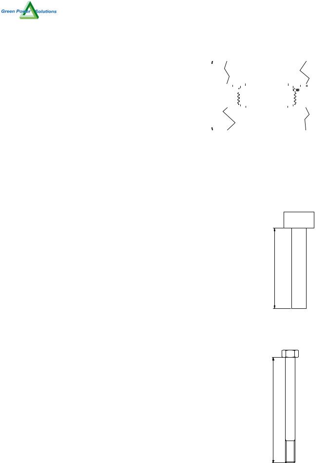
Ins. Length [mm] |
(4) |
Bolt Length [mm] |
T [mm] |
11 |
15 |
30 |
A |
|
50 |
Z |
100 |
115 |
21 |
25 |
40 |
A |
|
50 |
A |
110 |
125 |
31 |
35 |
50 |
B |
|
70 |
B |
120 |
135 |
41 |
45 |
60 |
B |
|
70 |
C |
130 |
145 |
51 |
55 |
70 |
C |
|
95 |
D |
140 |
155 |
61 |
65 |
80 |
C |
|
95 |
E |
150 |
165 |
71 |
75 |
90 |
C |
|
95 |
F |
160 |
175 |
** with additional bar spacer only |
|
|
|
|
|
|
||
Type GC89BR…R: suggested insulator/bolt types |
|
|
|
|||||
Allowed clearance S |
|
Insulator choice |
|
Bolt choice |
Max height |
|||
S' Min [mm]** |
S Min [mm] |
S Max [mm] |
(3) |
|
Ins. Length [mm] |
(4) |
Bolt Length [mm] |
T [mm] |
11 |
15 |
30 |
A |
|
50 *** |
Z |
100 |
129 |
21 |
25 |
40 |
A |
|
50 |
A |
110 |
139 |
31 |
35 |
50 |
A |
|
50 |
B |
120 |
149 |
41 |
45 |
60 |
B |
|
70 |
C |
130 |
159 |
51 |
55 |
70 |
B |
|
70 |
D |
140 |
169 |
61 |
65 |
80 |
B |
|
70 |
E |
150 |
179 |
71 |
75 |
90 |
C |
|
95 |
F |
160 |
189 |
** with additional bar spacer only |
|
|
*** For S Max |
|
|
|
||
Type GC89SN…R: suggested insulator/bolt types |
|
|
|
|||||
Allowed clearance S |
|
Insulator choice |
|
Bolt choice |
Max height |
|||
S' Min [mm]** |
S Min [mm] |
S Max [mm] |
(3) |
|
Ins. Length [mm] |
(4) |
Bolt Length [mm] |
T [mm] |
20 |
24 |
39 |
A |
|
50 |
Z |
100 |
110 |
30 |
34 |
49 |
B |
|
70 |
A |
110 |
120 |
40 |
44 |
59 |
B |
|
70 |
B |
120 |
130 |
50 |
54 |
69 |
C |
|
95 |
C |
130 |
140 |
60 |
64 |
79 |
C |
|
95 |
D |
140 |
150 |
70 |
74 |
89 |
C |
|
95 |
E |
150 |
160 |
80 |
84 |
99 |
D |
|
120 |
F |
160 |
170 |
** with additional bar spacer only |
|
|
|
|
|
|
||
Type GC89SR…R: suggested insulator/bolt types |
|
|
|
|||||
Allowed clearance S |
|
Insulator choice |
|
Bolt choice |
Max height |
|||
S' Min [mm]** |
S Min [mm] |
S Max [mm] |
(3) |
|
Ins. Length [mm] |
(4) |
Bolt Length [mm] |
T [mm] |
40 |
44 |
59 |
B |
|
70 |
Z |
100 |
129 |
50 |
54 |
69 |
B |
|
70 |
A |
110 |
139 |
60 |
64 |
79 |
B |
|
70 |
B |
120 |
149 |
70 |
74 |
89 |
C |
|
95 |
C |
130 |
159 |
80 |
84 |
99 |
C |
|
95 |
D |
140 |
169 |
90 |
94 |
109 |
D |
|
120 |
E |
150 |
179 |
100 |
104 |
119 |
D |
|
120 |
F |
160 |
189 |
** with additional bar spacer only Document GC89…RT001
3
4
 Loading...