


INSTRUCTION MANUAL MANUAL DE INSTRUCCIONES MANUEL D’INSTRUCTIONS
DM-20
Digital
Multimeter
Multímetro
digital
Contrôleur
numérique
Read and understand all of the instructions and safety information in this manual before operating or servicing this tool.
Lea y entienda todas las instrucciones y la información sobre seguridad que aparecen en este manual, antes de manejar esta herramienta o darle mantenimiento.
Lire attentivement et bien comprendre toutes les instructions et les informations sur la sécurité de ce manuel avant d‘utiliser ou de procéder à l‘entretien de cet outil.
999 6758.8 |
© 2004 Greenlee Textron Inc. |
12/04 |

Description
The Greenlee DM-20 Digital Multimeter is a hand-held testing device with the following measurement capabilities: AC and DC voltage, DC current, and resistance. It also checks diodes, verifies continuity, and tests 1.5 V and 9 V batteries.
Safety
Safety is essential in the use and maintenance of Greenlee tools and equipment. This instruction manual and any markings on the tool provide information for avoiding hazards and unsafe practices related to the use of this tool. Observe all of the safety information provided.
Purpose of This Manual
This instruction manual is intended to familiarize all personnel with the safe operation and maintenance procedures for the Greenlee DM-20 Digital Multimeter.
Keep this manual available to all personnel. Replacement manuals are available upon request at no charge.
All specifications are nominal and may change as design improvements occur. Greenlee Textron Inc. shall not be liable for damages resulting from misapplication or misuse of its products.
® Registered: The color green for electrical test instruments is a registered trademark of Greenlee Textron Inc.
KEEP THIS MANUAL
2
DM-20
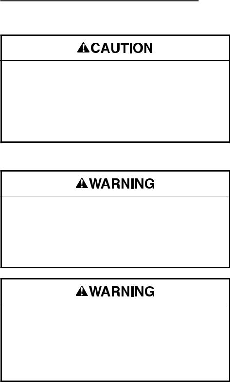
Important Safety Information
SAFETY ALERT SYMBOL
This symbol is used to call your attention to hazards or unsafe practices which could result in an injury or property damage. The signal word, defined below, indicates the severity of the hazard. The message after the signal word provides information for preventing or avoiding the hazard.
Immediate hazards which, if not avoided, WILL result in severe injury or death.
Hazards which, if not avoided, COULD result in severe injury or death.
Hazards or unsafe practices which, if not avoided, MAY result in injury or property damage.
Read and understand this material before operating or servicing this equipment. Failure to understand how to safely operate this tool could result in an accident causing serious injury or death.
3
Important Safety Information
Electric shock hazard:
Contact with live circuits could result in severe injury or death.
Electric shock and fire hazard:
•Do not expose this unit to rain or moisture.
•Do not use the unit if it is wet or damaged.
•Inspect the test leads before use. They must be clean and dry, and the insulation must be in good condition.
•Use this unit for the manufacturer’s intended purpose only, as described in this manual. Any other use can impair the protection provided by the unit.
Failure to observe these warnings could result in severe injury or death.
Electric shock hazard:
•Do not apply more than the rated voltage between any two input terminals, or between any input terminal and earth ground.
•Do not contact the test lead tips.
Failure to observe these warnings could result in severe injury or death.
4
DM-20
Important Safety Information
Electric shock hazard:
•Do not operate with the case open.
•Before opening the case, remove the test leads from the circuit and shut off the unit.
Failure to observe these warnings could result in severe injury or death.
Electric shock hazard:
The fuse is an integral part of the overvoltage protection. When fuse replacement is necessary, refer to “Specifications” for the correct type, size and capacity. Using any other type of fuse will void the overvoltage protection rating of the unit.
Failure to observe this warning could result in severe injury or death.
Electric shock hazard:
•Unless measuring voltage or current, shut off and lock out power. Make sure that all capacitors are discharged. Voltage must not be present.
•Using this unit near equipment that generates electromagnetic interference can result in unstable or inaccurate readings.
Failure to observe these warnings could result in severe injury or death.
5
Important Safety Information
Electric shock hazard:
Do not change the measurement function while the test leads are connected to a component or circuit.
Failure to observe this precaution may result in injury and can damage the unit.
Electric shock hazard:
•Do not attempt to repair this unit. It contains no user-serviceable parts.
•Do not expose the unit to extremes in temperature or high humidity. Refer to “Specifications.”
Failure to observe these precautions may result in injury and can damage the unit.
Set the selector and connect the test leads so that they correspond to the intended measurement. Incorrect settings or connections can result in a blown fuse.
Note: The test leads of this unit are not removable. Do not attempt to remove them.
6
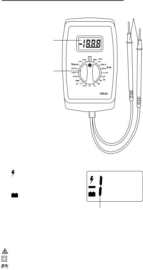
Identification
1.LCD display
2.Selector to select a function or turn power off
3.Permanently attached test leads and probes
1
2
DM-20
3
Display Icons
4.300 V AC or DC range
|
|
|
|
selected |
4 |
|
|
|
|
|
|
|
|
|
|
|
|
|
|
||
5. |
– |
Polarity indicator |
5 |
|
|
|
|
|
||
|
|
|
|
|
||||||
6. |
|
|
|
Low battery indicator |
6 |
|
|
|
|
|
|
|
|
|
|
|
|||||
|
|
|
|
|
|
|||||
|
|
|
|
|
|
|
|
|||
|
|
|
|
|
|
|||||
|
|
|
|
|
|
|||||
7.1 Overload indicator
7
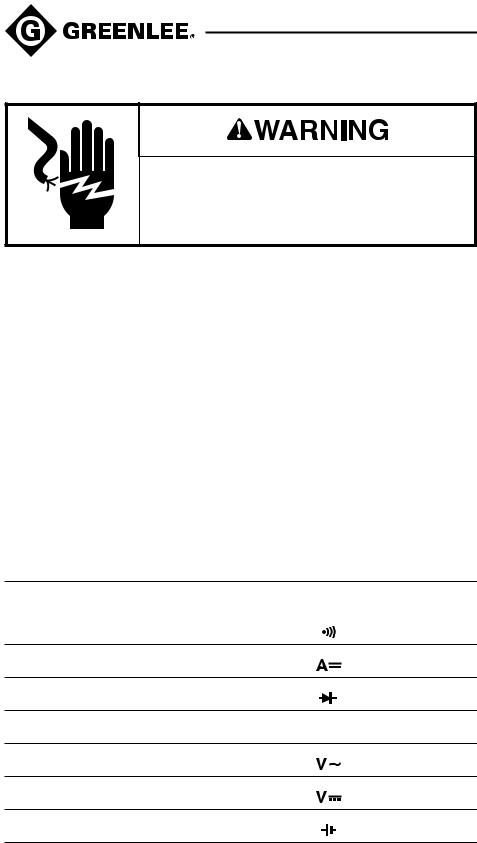
Symbols on the Unit
Warning—Read the instruction manual
Double insulation
Battery
7
Operation
Electric shock hazard:
Contact with live circuits could result in severe injury or death.
1.Refer to the Settings Table. Set the selector to the proper setting. Start with the highest measurement range.
2.Refer to “Typical Measurements” for specific measurement instructions.
3.Test the unit on a known functioning circuit or component.
•If the unit does not function as expected on a known functioning circuit, replace the battery and/or fuses.
•If the unit still does not function as expected, send the unit to Greenlee for repair. Refer to the instructions under the Warranty.
4.Take the reading from the circuit or component to be tested. If the resolution is not satisfactory, remove the meter from the circuit and change to the next lower range.
Settings Table
To measure this value: |
Set the selector to this symbol: |
|
|
Continuity*
Current (DC)**
Diode
Resistance |
Ω |
Voltage (AC)
Voltage (DC)
Battery
*Tone sounds if the measured resistance is less than approximately 25 Ω.
**Connect the unit in series with the test object and then switch the test object on.
8

DM-20
Typical Measurements
Voltage Measurement
Current Measurement
9
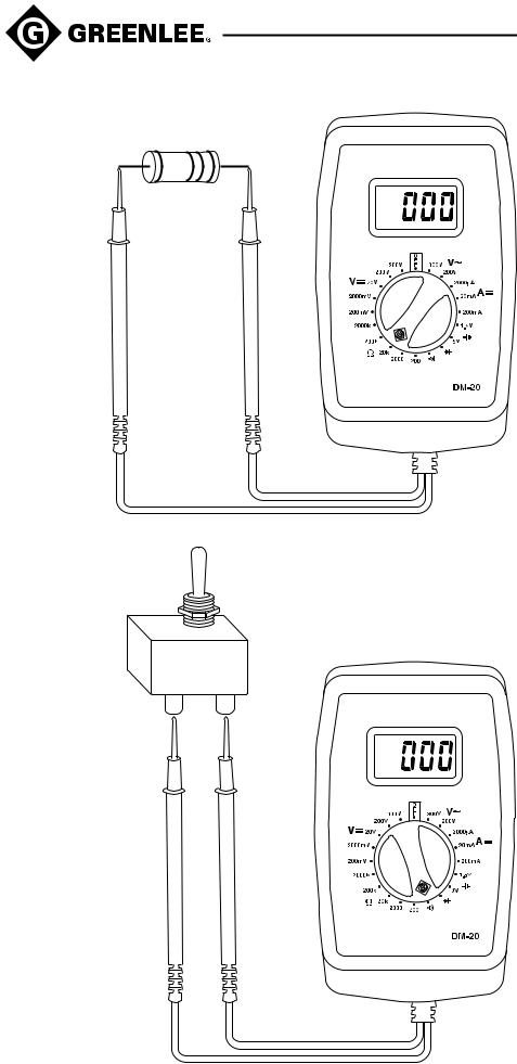
Typical Measurements
Resistance
Measurement
Continuity
Check
10
DM-20
Typical Measurements
Diode Measurement
Reverse Bias
Forward Bias
Red Probe
11

Accuracy
Refer to “Specifications” for operating conditions and temperature coefficient.
Accuracy is specified as follows: ± (a percentage of the reading + a fixed amount) at 23 ° C± 5 ° C (73.°4F± 9 ° F), 0% to 80% relative humidity.
DC Current
Range |
Accuracy |
Burden Voltage |
|
1999 A |
± (2.5% |
+ 4 A) |
|
19.99 mA |
± (2.5% |
+ 0.04 mA) |
< 0.7 V |
199.9 mA |
± (2.5% |
+ 0.4 mA) |
|
AC Voltage
|
|
|
Frequency |
Input |
|
Range |
Accuracy |
Range |
Impedance |
||
199.9 V |
± (1.5% |
+ 0.4 V) |
45 to 400 Hz |
0.5 MΩ |
|
300 V |
± (2.0% |
+ 4 V) |
|||
|
|
||||
DC Voltage
Range |
Accuracy |
Input Impedance |
|
199.9 mV |
± (1.2% + 0.2 mV) |
|
|
1.999 V |
± (1.2% |
+ 0.002 V) |
|
19.99 V |
± (1.2% |
+ 0.02 V) |
1 MΩ |
199.9 V |
± (1.2% |
+ 0.2 V) |
|
300 V |
± (1.5% |
+ 2 V) |
|
Resistance
Range |
Accuracy |
Typical Open Circuit Voltage |
|
199.9 Ω |
± (1.5% + 0.5 Ω) |
3.2 VDC |
|
1999 Ω |
± (1.5% |
+ 0.005 kΩ) |
|
19.99 kΩ |
± (1.5% |
+ 0.05 kΩ) |
|
199.9 kΩ |
± (1.5% |
+ 0.5 kΩ) |
> 0.3 VDC |
1999 kΩ |
± (2.0% |
+ 0.004 MΩ) |
|
12

DM-20
Accuracy (cont’d)
Battery Test
Test Current: Approximately 14 mA for 1.5 V, 8 mA for 9 V Accuracy: ± (5% + 0.1 V)
Diode Test
Open Circuit Voltage: 3.2 VDC (maximum)
Test Current (Typical): 1.0 mA
Continuity
Tone indicates continuity. Threshold is approximately 30 Ω . Resolution: 1 Ω
Open Circuit Voltage: 3.2 VDC (maximum)
Specifications
Display: 3-1/2–digit LCD (1999 maximum count)
Polarity: Automatic
Sampling Rate: 2.5 per second
Temperature Coefficient: 0.1 x (accuracy) per ° C below 18° C or above 28 ° C
Overload Protections:
mA and Battery Test: 0.315 A/250 V F fuse, interrupting rating 1500 A, 5 mm x 20 mm
All Other Functions: 300 VAC RMS and 300 VDC
Measurement Category: Category II, 300 V
Operating Conditions: |
0 ° C to 40° C (32° F to 104 |
° F), |
0 to 80% relative humidity |
|
|
Altitude: 2000 m (6500’) maximum |
|
|
Indoor use only |
|
|
Pollution Degree: |
2 |
|
Storage Conditions: –10 ° C to 60° C (14° F to 140° F), 0 to 70% relative humidity
Remove battery
Battery: 9-Volt battery (NEDA 1604, JIS 006P or IEC 6F22)
13

Measurement Categories
These definitions were derived from the international safety standard for insulation coordination as it applies to measurement, control, and laboratory equipment. These measurement categories are explained in more detail by the International Electrotechnical Commission; refer to either of their publications: IEC 61010-1 or IEC 60664.
Measurement Category I
Signal level. Electronic and telecommunication equipment, or parts thereof. Some examples include transient-protected electronic circuits inside photocopiers and modems.
Measurement Category II
Local level. Appliances, portable equipment, and the circuits they are plugged into. Some examples include light fixtures, televisions, and long branch circuits.
Measurement Category III
Distribution level. Permanently installed machines and the circuits they are hard-wired to. Some examples include conveyor systems and the main circuit breaker panels of a building’s electrical system.
Measurement Category IV
Primary supply level. Overhead lines and other cable systems. Some examples include cables, meters, transformers, and other exterior equipment owned by the power utility.
Statement of Conformity
Greenlee Textron Inc. is certified in accordance with ISO 9000 (2000) for our Quality Management Systems.
The instrument enclosed has been checked and/or calibrated using equipment that is traceable to the National Institute for Standards and Technology (NIST).
14
DM-20
Maintenance
Electric shock hazard:
•Do not attempt to repair this unit. It contains no user-serviceable parts.
•Do not expose the unit to extremes in temperature or high humidity. Refer to “Specifications.”
Failure to observe these precautions may result in injury and can damage the unit.
Battery and Fuse Replacement
Electric shock hazard:
•Do not operate with the case open.
•Before opening the case, remove the test leads from the circuit and shut off the unit.
Failure to observe these warnings could result in severe injury or death.
Electric shock hazard:
The fuse is an integral part of the overvoltage protection. When fuse replacement is necessary, refer to “Specifications” for the correct type, size and capacity. Using any other type of fuse will void the overvoltage protection rating of the unit.
Failure to observe this warning could result in severe injury or death.
1.Disconnect the unit from the circuit. Turn the unit OFF.
2.Remove the screws from the back cover. Remove the back cover.
3.Replace the battery (observe polarity) and/or fuse.
4.Replace the cover and screws.
15
 Loading...