

Page 1
INSTRUCTION MANUAL
HK520
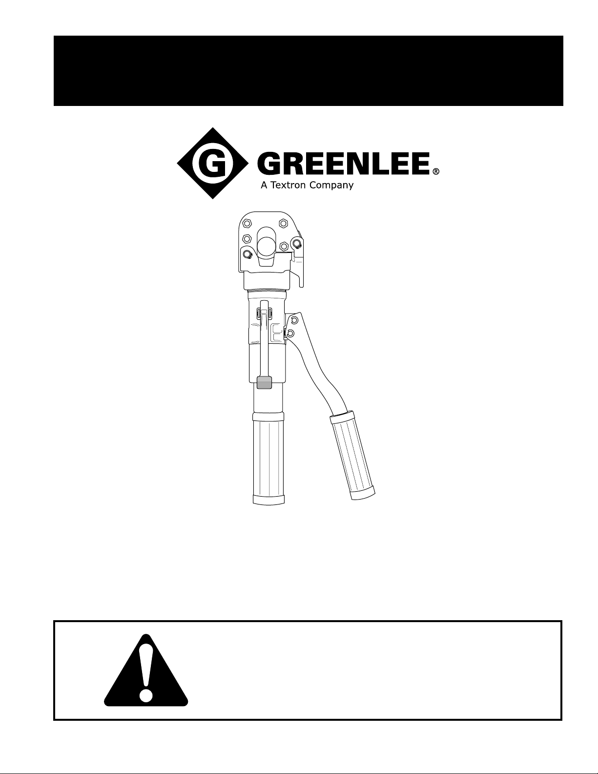
Hydraulic Cable Cutter
Read and understand all of the instructions and
safety information in this manual before operating
or servicing this tool.
999 4017.5 © 2003 Greenlee Textron IM 1539 REV 3 2/03
Page 2

HK520 Hydraulic Cable Cutter
Table of Contents
Description .....................................................................2
Safety .............................................................................2
Purpose of this Manual .................................................. 2
Important Safety Information......................................3–4
Operation ....................................................................... 5
Maintenance...................................................................6
Troubleshooting ............................................................. 7
Exploded View ............................................................... 8
Parts List ........................................................................9
Description
The HK520 Cable Cutter is intended to cut copper
and aluminum cable up to 350 MCM, 397 ACSR,
1/2" reinforcement bar (rebar), 1/2" guy wire and
3/4" wire rope. It is not intended for use on
EHS guy wire.
Safety
Safety is essential in the use and maintenance of
Greenlee tools and equipment. This instruction manual
and any markings on the tool provide information for
avoiding hazards and unsafe practices related to the
use of this tool. Observe all of the safety information
provided.
Purpose
This instruction manual is intended to familiarize
personnel with the safe operation and maintenance
procedures for the Greenlee HK520 Cable Cutter.
Keep this manual available to all personnel.
Replacement manuals are available upon request
at no charge.
All specifications are nominal and may change as design improvements occur. Greenlee Textron shall not be liable for damages
resulting from misapplication or misuse of its products.
KEEP THIS MANUAL
Greenlee / A Textron Company 2 4455 Boeing Dr. • Rockford, IL 61109-2988 USA • 815-397-7070
Page 3
IMPORTANT SAFETY INFORMATION
SAFETY
ALERT
SYMBOL
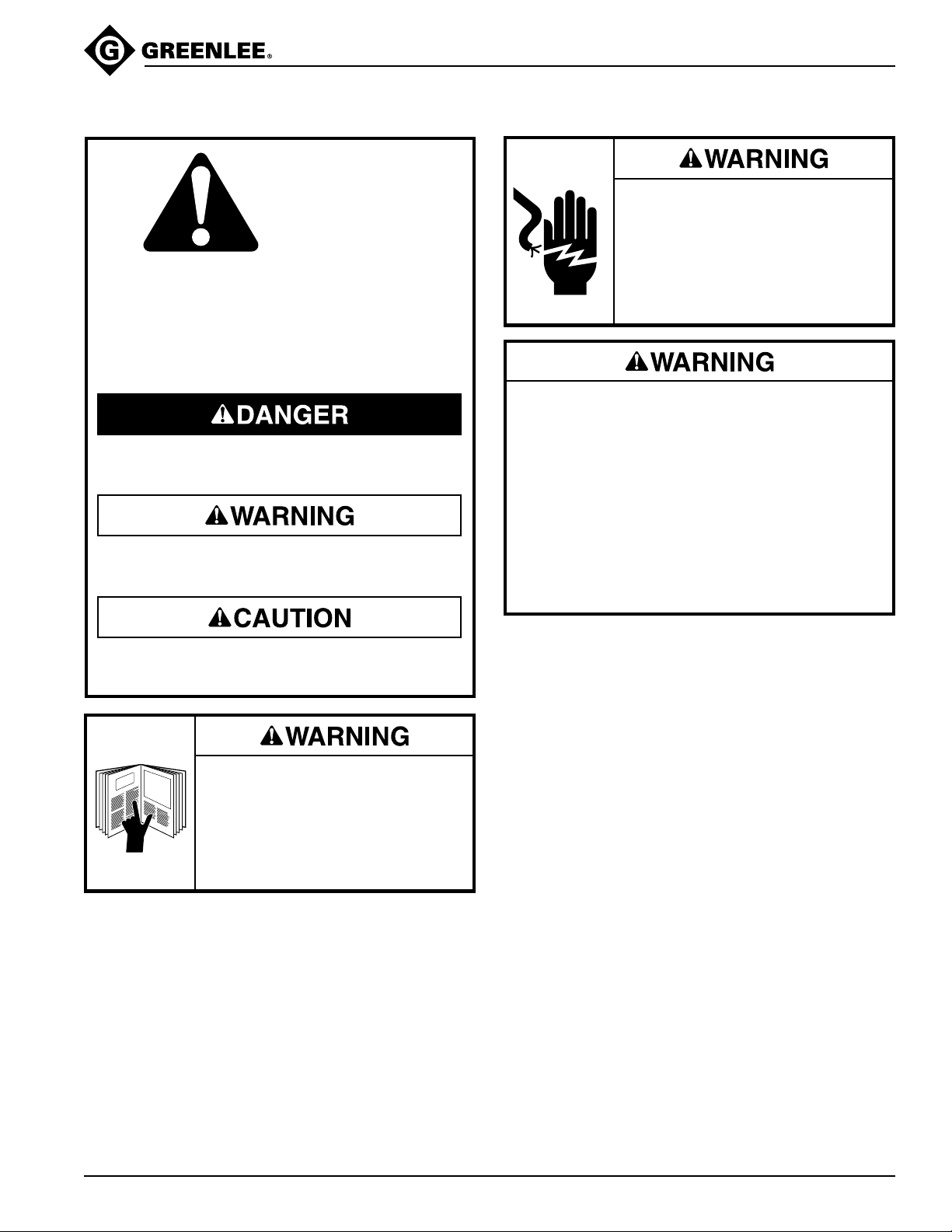
This symbol is used to call your attention to hazards
or unsafe practices which could result in an injury
or property damage. The signal word, defined below,
indicates the severity of the hazard. The message
after the signal word provides information for
preventing or avoiding the hazard.
Immediate hazards which, if not avoided, WILL
result in severe injury or death.
Hazards which, if not avoided, COULD result in
severe injury or death.
HK520 Hydraulic Cable Cutter
Electrical Shock Hazard: This tool
is not insulated. Use protective
equipment when utilizing this unit
near energized electrical lines.
Failure to observe this warning
could result in severe injury or
death.
• Electrical Shock Hazard: The owner of this cutter
must be certain that all users of this tool are
trained in the applicable safety codes and
standards, as well as, in the safe use of this tool
and its accessories.
• Do not cut cable under tension.
• This tool is intended for two-handed operation.
Maintain a firm grip on both handles during
operation.
Failure to observe these warnings could result in
severe injury or death.
Hazards or unsafe practices which, if not avoided,
MAY result in injury or property damage.
Read and understand all of the
instructions and safety information
in this manual before operating or
servicing this tool.
Failure to observe this warning will
result in severe injury or death.
Greenlee / A Textron Company 3 4455 Boeing Dr. • Rockford, IL 61109-2988 USA • 815-397-7070
Page 4
HK520 Hydraulic Cable Cutter
IMPORTANT SAFETY INFORMATION
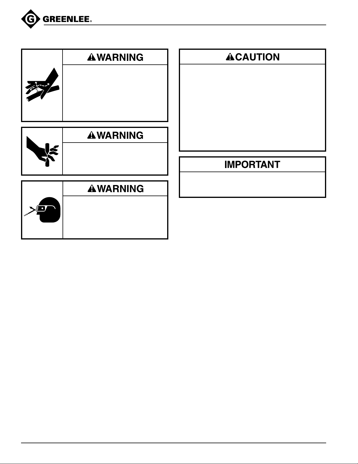
High Pressure Hazard:
Do not use fingers or hands to
check for oil leaks. High pressure
oil easily punctures skin causing
serious injury, gangrene or death.
If injured seek medical help immediately to remove oil.
Keep hands and fingers away from
closing blades.
Wear eye protection when operating
or servicing this tool.
Failure to wear eye protection can
result in serious eye injury from
flying debris or hydraulic oil.
• Inspect the tool before use. Replace any worn
or damaged parts. A damaged or improperly
assembled tool can malfunction, injuring nearby
personnel.
• Do not perform any service or maintenance other
than as described in this manual. Injury or damage
to the tool may result.
• Use this tool for the manufacturer’s intended
purpose only. Use other than that which is
described in this manual could result in injury
or property damage.
Do not place the tool in a vise. The cutter is
designed for hand-held operation.
Greenlee / A Textron Company 4 4455 Boeing Dr. • Rockford, IL 61109-2988 USA • 815-397-7070
Page 5
Operation
Electrical Shock Hazard: This tool
is not insulated. Use protective
equipment when utilizing this unit
near energized electrical lines.
Failure to observe this warning
could result in severe injury or
death.
Keep hands and fingers away from
closing blades.
HK520 Hydraulic Cable Cutter
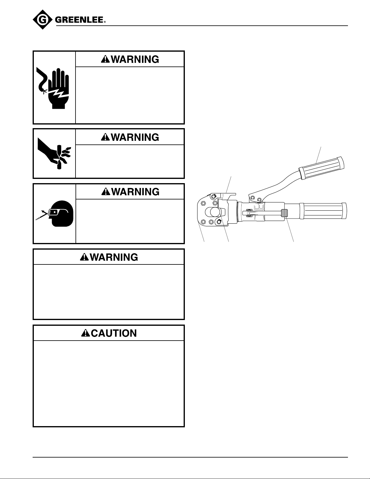
1. Lift the head latch to open the cutter.
2. Place the material to be cut between the jaws.
3. Close the head latch completely.
4. Align the material at a 90° angle to the blades.
5. Pump the pump handle to advance the blade.
6. When the cut is complete, press the release lever to
retract the blade.
Note: Do not continue to advance the blade after the cut
is finished. This could cause the cable cutter to jam.
Pump Handle
Head Latch
Wear eye protection when operating
or servicing this tool.
Failure to wear eye protection can
result in serious eye injury from
flying debris or hydraulic oil.
• Do not cut cable under tension.
• This tool is intended for two-handed operation.
Maintain a firm grip on both handles during
operation.
Failure to observe these warnings could result in
severe injury or death.
• Inspect the tool before use. Replace any worn or
damaged parts. A damaged or improperly
assembled tool can malfunction, injuring nearby
personnel.
• Do not perform any service or maintenance other
than as described in this manual. Injury or damage
to the tool may result.
• Use this tool for the manufacturer’s intended
purpose only. Use other than that which is
described in this manual could result in injury or
property damage.
Cutting
Head
Cutting Blade
Release Lever
Greenlee / A Textron Company 5 4455 Boeing Dr. • Rockford, IL 61109-2988 USA • 815-397-7070
Page 6
Maintenance
Wear eye protection when operating
or servicing this tool.
Failure to wear eye protection can
result in serious eye injury from
flying debris or hydraulic oil.
Do not perform any service or maintenance other
than as described in this manual. Injury or damage
to the tool may result.
HK520 Hydraulic Cable Cutter
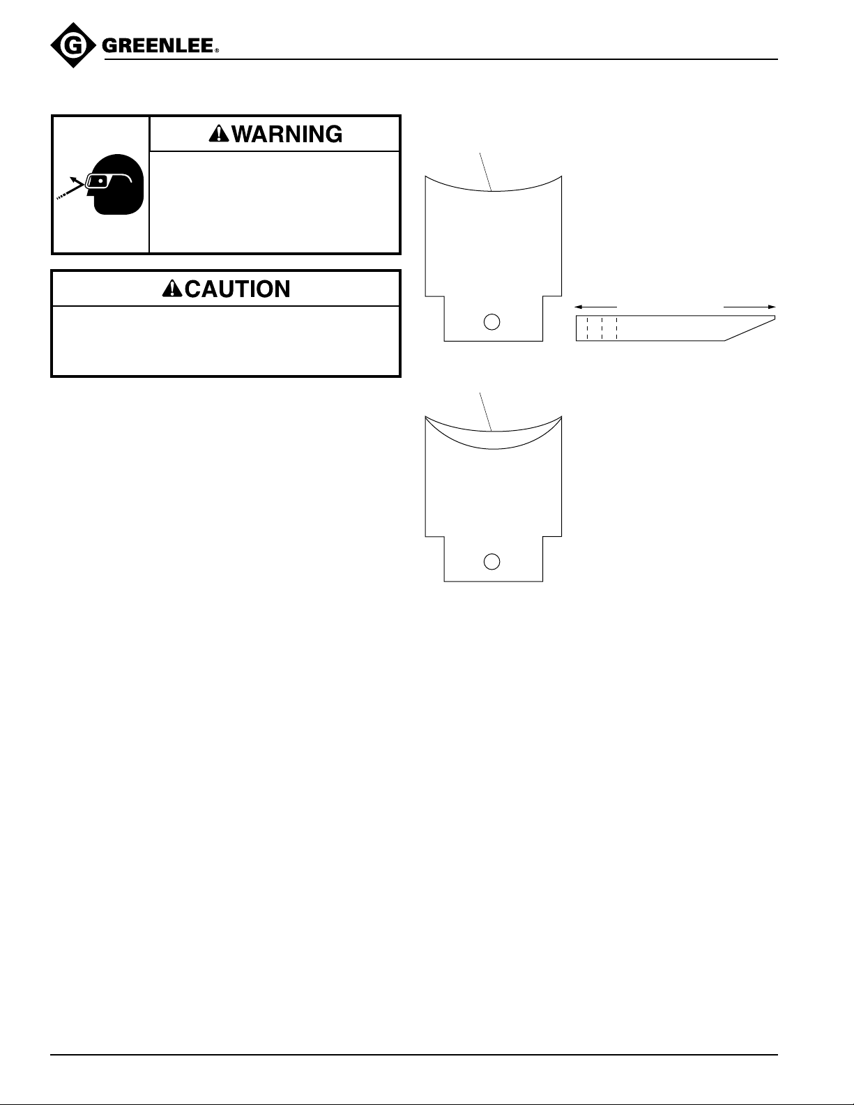
Blade Sharpening Instructions
Edge should be flat
1. Set blade on flat surface with
beveled edge facing down
(see Figure A)
BACK SIDE
Beveled Edge
2. Use a sharpening stone to
remove all burrs from back
surface.
Figure A
Flatten this surface.
Use a spray lubricant to keep the cutting head free of
grit, dirt and metal chips.
FRONT SIDE
3. Use a high-speed dremeltype tool to flatten top edge
of blade (approximately
1/32" wide flat).
Do not leave a sharp edge.
This will cause chipping of
cutting surface and will
decrease blade life.
Greenlee / A Textron Company 6 4455 Boeing Dr. • Rockford, IL 61109-2988 USA • 815-397-7070
Page 7
HK520 Hydraulic Cable Cutter
Troubleshooting
Problem Probable Cause Possible Remedy
Cutting blade does not advance. Check balls are not properly seated. Seat check ball (47) into induction
Ram advances but will not build valve (48).
enough pressure to cut.
Hydraulic fluid level is low, or there is Remove main handle (55) exposing
air in the system. bladder (51). Remove plug (52). Fill
with oil and replace plug (52).
Blade does not retract after cut Debris is caught between the moving Unlatch the head. Press down on the
is completed. blade and the cutter head. release lever (31). Jog the head back
and forth to free the blade. If the blade
still doesn’t retract, spray the head and
moveable blade with a spray lubricant
and repeat.
Release lever (31) cannot be Check ball will not unseat. Place the tip of a screwdriver directly
depressed. on the release valve stem (34) under
the release lever (31). Using the
screwdriver as a lever, pull up on the
screwdriver handle to depress the
release ball stem.
Blades do not cut cleanly. Blades are dull. See blade sharpening instructions and
diagrams.
Greenlee / A Textron Company 7 4455 Boeing Dr. • Rockford, IL 61109-2988 USA • 815-397-7070
Page 8
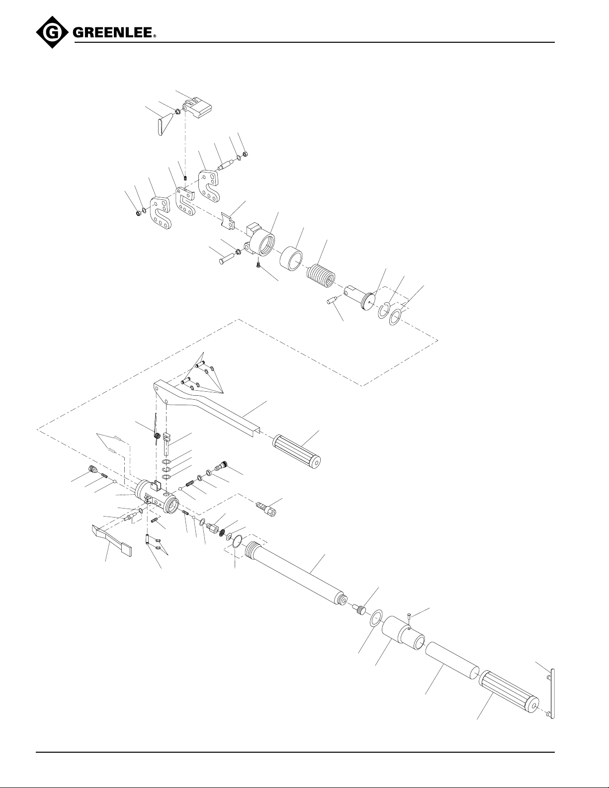
Exploded View
7
10
HK520 Hydraulic Cable Cutter
1
9
8
7
10
6
3
2
4
5
11
13
60
9
8
59
14
15
16
17
21
20
19
58
34
31
18
35
22
32
36
33
46
47
26
25
24
23
37
27
45
38
39
28
48
40
43
49
12
29
30
41
44
50
51
52
54
42
53
55
56
Greenlee / A Textron Company 8 4455 Boeing Dr. • Rockford, IL 61109-2988 USA • 815-397-7070
57
Page 9

Parts List
HK520 Hydraulic Cable Cutter
Key Part No. Description Qty
1 500 0333.0 Locking jaw ....................................................... 1
2 500 0304.6 Spring................................................................ 1
3 500 0301.1 Fixing blade....................................................... 1
4 500 0302.0 Blade spacer ..................................................... 1
5 500 0303.8 Front blade ........................................................ 1
6 500 0228.7 Stud................................................................... 4
7 500 0226.0 Nut .................................................................... 8
8 500 0332.1 Pivot .................................................................. 2
9 500 0331.3 Circlip ................................................................ 2
10 500 0227.9 Washer.............................................................. 8
11 500 0336.4 Moving blade..................................................... 1
12 500 0487.5 Fixing screw ...................................................... 1
13 500 0335.6 Spindle hub ....................................................... 1
14 500 0316.0 Spring................................................................ 1
15 500 0488.3 Output piston..................................................... 1
16* 500 0489.1 Back-up ring ...................................................... 1
17* 500 0490.5 O-ring ................................................................ 1
18 500 1036.0 Main body ......................................................... 1
19 500 0579.0 7/32" ball ........................................................... 1
20 500 0492.1 Spring................................................................ 1
21 500 0491.3 Valve screw....................................................... 1
22 500 1016.6 Spring................................................................ 1
23* 500 1035.2 Oil ring............................................................... 1
24* 500 1034.4 Back-up ring ...................................................... 1
25* 500 1033.6 Oil seal .............................................................. 1
26 500 1028.0 Pump piston ...................................................... 1
27 500 1043.3 Pin ..................................................................... 2
28* 500 1044.1 Snap ring ........................................................... 4
29 500 1045.0 Pump handle ..................................................... 1
30 500 1048.4 Pump handle grip .............................................. 1
Key Part No. Description Qty
31 500 1019.0 Release lever .................................................... 1
32 500 1072.7 Pin ..................................................................... 1
33* 500 1023.9 Snap ring........................................................... 2
34 500 1015.8 Release valve stem........................................... 1
35* 500 1014.0 O-ring ................................................................ 1
36 500 1021.2 Spring................................................................ 1
37 500 1037.9 7/32" Ball........................................................... 1
38 500 1038.7 Spring................................................................ 1
39* 500 1039.5 O-ring ................................................................ 1
40* 500 1040.9 Back-up ring ...................................................... 1
41 500 1041.7 Valve screw....................................................... 1
42* 500 1058.1 O-ring ................................................................ 1
43* 500 1054.9 O-ring ................................................................ 1
44 500 1062.0 Relief valve ....................................................... 1
45* 500 1052.2 Copper gasket ................................................... 1
46* 500 1049.2 Spring ................................................................ 1
47* 500 1050.6 3/16" Ball ........................................................... 1
48* 500 1053.0 Suction valve screw assy .................................. 1
49* 500 0330.5 Oil screen .......................................................... 1
50* 500 0334.8 Screen holder.................................................... 1
51 500 1055.7 Oil reservoir....................................................... 1
52 500 1056.5 Filler cap ........................................................... 1
53 500 1065.4 Body handle head ............................................. 1
54 500 1066.2 Spring pin .......................................................... 1
55 500 1060.3 Body handle ...................................................... 1
56 500 1061.1 Body handle grip ............................................... 1
57 500 1068.9 Holding band ..................................................... 1
58 501 0868.9 Spring pin .......................................................... 2
59 501 0869.7 Screw ................................................................ 1
60 501 0870.0 Ring cover ......................................................... 1
* 500 1078.6 Seal kit (includes items marked with asterisk)
501 0620.1 Stud kit (includes items 6,7,10)
501 0621.0 Pivot kit (includes items 8,9)
Greenlee / A Textron Company 9 4455 Boeing Dr. • Rockford, IL 61109-2988 USA • 815-397-7070
Page 10

www.greenlee.com
USA (800) 435-0786 Fax: (800) 451-2632
(815) 397-7070 Fax: (815) 397-1865
Canada (800) 435-0786 Fax: (800) 524-2853
International +1 (815) 397-7070 Fax: +1 (815) 397-9247
4455 Boeing Drive, Rockford, IL 61109-2988 • USA • 815-397-7070
An ISO 9001 Company • Greenlee Textron is a subsidiary of Textron Inc.
 Loading...