

Page 1
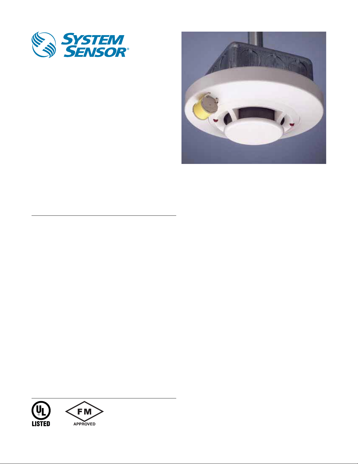
Duct Smoke Detector for
Special Applications
The System Sensor 2151 low-profile photoelectronic
smoke detector is UL listed to UL 268A specifically for
use in no-flow/low-flow air-handling systems.
Features
• Low-profile smoke detector design
• Low standby current
• Two LEDs blink in standby
• Detector head plugs easily into base
• Built-in test switch
• Built-in tamper-resistant feature
• Field sensitivity metering of detector to meet the requirements of
NFPA 72
• 120VAC and 24VAC/DC bases with built-in shorting spring
• Designed for mounting on standard electrical box
• SEMS screws for easy wiring and positive wire retention
• Removable cover and insect screen for field cleaning
The 2151 is designed for installations where a standard Venturi
principle duct smoke detector is unsuitable. This is the perfect
combination for installation in ducts where the air velocity is below
500 fpm or for duct sizes as small as 8 inches in diameter.
Pendant mounted in a standard electrical box within the duct, the
twist-in/twist-out head allows easy removal from the base for quick
cleaning and maintenance. The detector can be combined with the
System Sensor B114LP 120VAC base or the B114LPBT 24VAC/DC
base.
Remote testing is accomplished using our RTC100 Remote Test Coil
with Low Profile ring accessory that includes the RTS151.
The APA151, Remote Annunciator with Piezo Alarm, can also be
connected to provide an audible and visible indication of smoke
detector status.
Agency Listings
S911
Page 2
2151 Photoelectronic Detector Specifications
Architectural/Engineering Specifications
The air duct smoke detector shall be a System Sensor model 2151 Series Smoke detector UL listed to UL 268A specifically for use in air handling systems when
used in conjunction with the B114LP (120 VAC) base or the B114LPBT (24VAC/DC) base. The detector shall operate at air velocities up to 3000 feet per minute.
It shall be capable of local testing via magnetic switch or remote testing using the UL listed RTC100 Remote Test Coil accessory with the RTS151 Remote Test
Station. It shall be capable of providing duct smoke detector status via the UL listed model APA151 Piezo Annunciator.
Physical Specifications Electrical/Operating Specifications
Size 1.66˝ (4.22cm) H, 6.1˝ (155mm) dia. flanged base Operating Voltage/Alarm Current See Base Specifications
Weight 3.6 oz. (104 g) Standby current 85 μA maximum
Operating Temperature Range 32˚F to 120˚F (0˚C to 49˚C) Sensitivity 3%±.7% / ft.
Operating Humidity Range 10 to 93% RH non-condensing Air Velocity Rating 0 to 3000 fpm
Construction Flame retardant thermoplastic
B114LP/B114LPBT Adapter Base Specifications
Electrical Specifications
Loop Type 4-wire
Current Limit Resistor Yes
Alarm Contact Type Form A&C + A supply
Nominal Voltage B114LP: 120 VAC; B114LPBT: 24VAC/DC
Alarm Current (mA) 75 mA AC Max.
Relay Contact Ratings Resistive or Inductive (60% power factor) load. Form A: 2.0A at 30 VAC/DC; Form C: 0.6A at 110VDC, 2.0A at 30VDC;
1.0A at 125VAC, 2.0A at 30VAC
B114LP/B114LPBT Junction Box Specifications
Box depth contingent on base and wire size. Refer to National Electric Code or local applicable codes for appropriate recommendations.
Single Gang 3½˝ Octagon 4˝ Octagon 4˝ Square 50mm 60mm 75mm
No No Yes Yes No No No
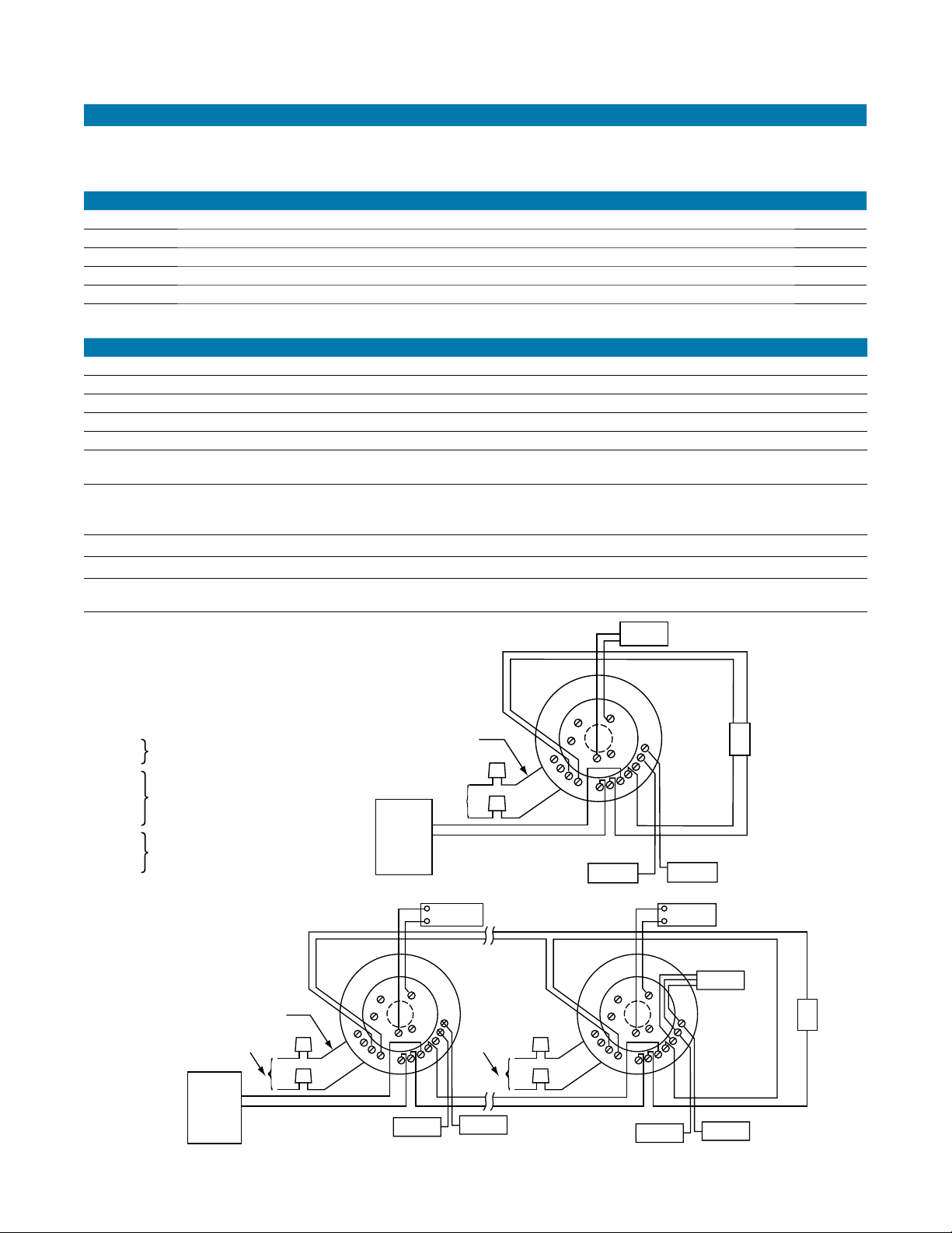
B114LP Typical Wiring Diagrams
B114LP Base Terminals
No. Function
1 Remote Annunciator (+)
2 Not Used
3 Not Used
4 Remote Annunciator (–)
5 Not used
6 N.O. Supervisory Relay
7 N.O. Form A Contacts
8 N.O. Alarm Relay
9 N.O. Form A
10 C. Initiation
11 C. Contacts
12 N.O. Alarm Relay
13 N.C. Form C
14 C. Auxiliary Contacts
BLACK LEADS
TRANSFORMER
PRIMARY
120 VAC
FIRE
A05-1018-004
ALARM
CONTROL
PANEL
ALARM INITIATION LOOP
1
9
8
POWER
2
6
RA100Z
(Optional)
4
14
5
13
12
11
10
(+)
(–)
4
3
5
1
7
9
8
POWER
BLACK LEADS
TRANSFORMER
PRIMARY
120 VAC
FIRE
ALARM
CONTROL
PANEL
3
2
1
6
7
8
POWER RELEASING
(+)
(–)
4
5
11
10
9
ALARM INITIATION LOOP
RA100Z
(Optional)
14
13
12
120 VAC
RELEASING
DEVICE
3
2
6
7
11
10
FAN/DAMPER
CONTROL
RA100Z
(Optional)
14
13
12
RELEASING
DEVICE
DEVICE
EOL
SPECIFIED
BY PANEL
MANUFACTURER
EOL
SPECIFIED
BY PANEL
MANUFACTURER
S02809-01
S0279-01
Page 3

B114LPBT Typical Wiring Diagrams
B114LPBT Base Terminals
No. Function
1 Remote Annunciator (+)
2 Test Coil (+)
3 Not Used
4 Remote Annunciator (–)
5 RTC (–)
6 C. Supervisory Relay
7 N.O. Form A Contacts
8 N.O. Alarm Relay
9 N.O. Form A
10 C. Initiation
11 C. Contacts
12 N.O. Alarm Relay
13 N.C. Form C
14 C. Auxiliary Contacts
3
APA151
2
(Optional)
1
7
RELEASING
DEVICE
1
9
8
POWER
4
14
5
13
12
11
10
H0269-01
FAN / DAMPER
SHUTDOWN
3
2
24 VACrms/DC
3
APA151
2
(Optional)
1
RELEASING
3
4
DEVICE
3
6
3
APA151
2
(Optional)
1
4
2
5
24 VACrms/DC 24 VACrms/DC
FIRE
ALARM
CONTROL
PANEL
ALARM INITIATION LOOP
1
6
7
8
13
12
11
10
9
14
2
1
6
7
8
14
5
13
12
11
10
9
EOL
SPECIFIED
BY PANEL
MANUF
RTC100 Wiring Diagram Ring Replacement on B114LP/B114LPBT
NOTE: Installation and wiring of the
test coil is required. Please see
B114LP/B114LPBT RTS151
ANNUNCIATOR (+)
REMOTE
TEST COIL (+)
1
2
3
FIELD
INSTALLED
JUMPER
TEST
COIL
RTC (–)
4
5
1
2
3
4
5
ALARM
RTC100 Installation & Maintenance
Instructions.
H0191-01
4-POSITION
TERMINAL
BLOCK
TEST
COIL
ACTURER
H0268-01
H01999-00
A05-1018-004
Page 4

Accessories
RTS151
Remote Test Station
APA151
Piezo Annunciator
(provided with RTC100
Remote Test Coil Kit)
Top Mount in Ventilation Shaft
Ordering Information
Part No. Description
2151 Low-profile photoelectric plug-in detector (order one of the bases listed below and RTC100)
B114LP 120VAC detector base
B114LPBT 24VAC/DC detector base
RTC100 Remote test coil kit with low profile ring (Incl. RTS151 remote test station)
Accessories
APA151 Remote annunciator with piezo alarm
RA100Z Remote annunciator
RA100Z
Remote Annunciator
3825 Ohio Avenue • St. Charles, IL 60174
Phone: 800-SENSOR2 • Fax: 630-377-6495
Product specifications subject to change without notice. Visit systemsensor.com for
current product information, including the latest version of this data sheet.
©2009 System Sensor.
A05-1018-005 • 8/09 • #2220
 Loading...