

Page 1
NM Series Direct Coupled Actuator
Minimum 90 in-lb torque
L For damper areas up to 22 sq-ft*
All Actuators
have BDCM
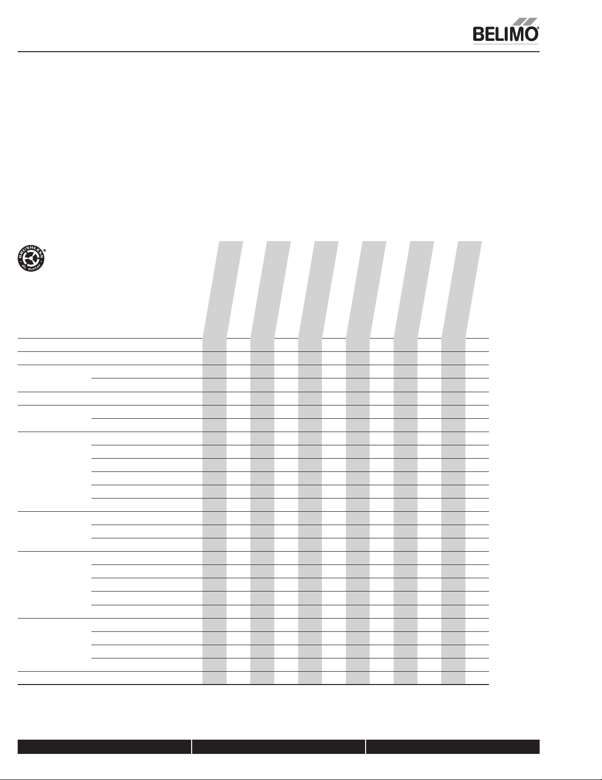
NM Series - At A Glance
Basic Product
Flexible Product
Torque 90 in-lb [10 Nm]
70 in-lb [8 Nm]**
Angle of Rotation 95 degrees
Power Supply 24 VAC/DC
100 to 240 VAC
Control Input On/Off
On/Off, Floating Point
2 to 10 VDC (4 to 20mA)
Multi-Function Technology
0 to 135 Ohm
0 to 20V Phasecut
Feedback None
2 to 10 VDC
Variable (0 to 10 VDC)
Running Time 95 seconds
45 seconds
Adj. 45 to 150 seconds
Adj. 20 to 75 seconds
Adj. 4 to 15 seconds
Wiring Plenum Rated Cable
Appliance Rated Cable
Terminal Strip
Conduit Fitting
Auxiliary Switch Add-On
Installation and Operation… (page 265).
NMCB24-3 (p. 170)
NMB(X)24-3 (p. 170)
LL LL LL LL
L LL LLLLLLL
LLLLLLLLLL
LLLLLLLLLLLL
LL LL LLLLLL
LL
LLL
LLLL L
LL
LL
LLLLLLL
LL LL LLLLLL
LL
LL
LLLLLLLLLLLL
LLLLLLLLL LL
NMB(X)24-SR (p. 176)
NMX120-3 (p. 174)
LLLL
LLL
NMCB24-SR (p. 178)
NMB(X)24-MFT (p. 182)
NMX120-SR (p. 180)
LLL
LLL L
NMX24-PC (p. 188)
NMX24-MFT95 (p. 186)
L
NMCX24-MFT (p. 184)
L
NMQB(X)24-1 (p. 190)
NMQB(X)24-MFT (p. 192)
LL
L
LL
K20901 - 01/09 - Subject to change. © Belimo Aircontrols (USA), Inc.
*Based on 4 in-lb/ft2 damper torque loading. Parallel blade. No edge seals.
**Torque variable based on running time.
800-543-9038 USA 866-805-7089 CANADA 203-791-8396 LATIN AMERICA
168
Page 2
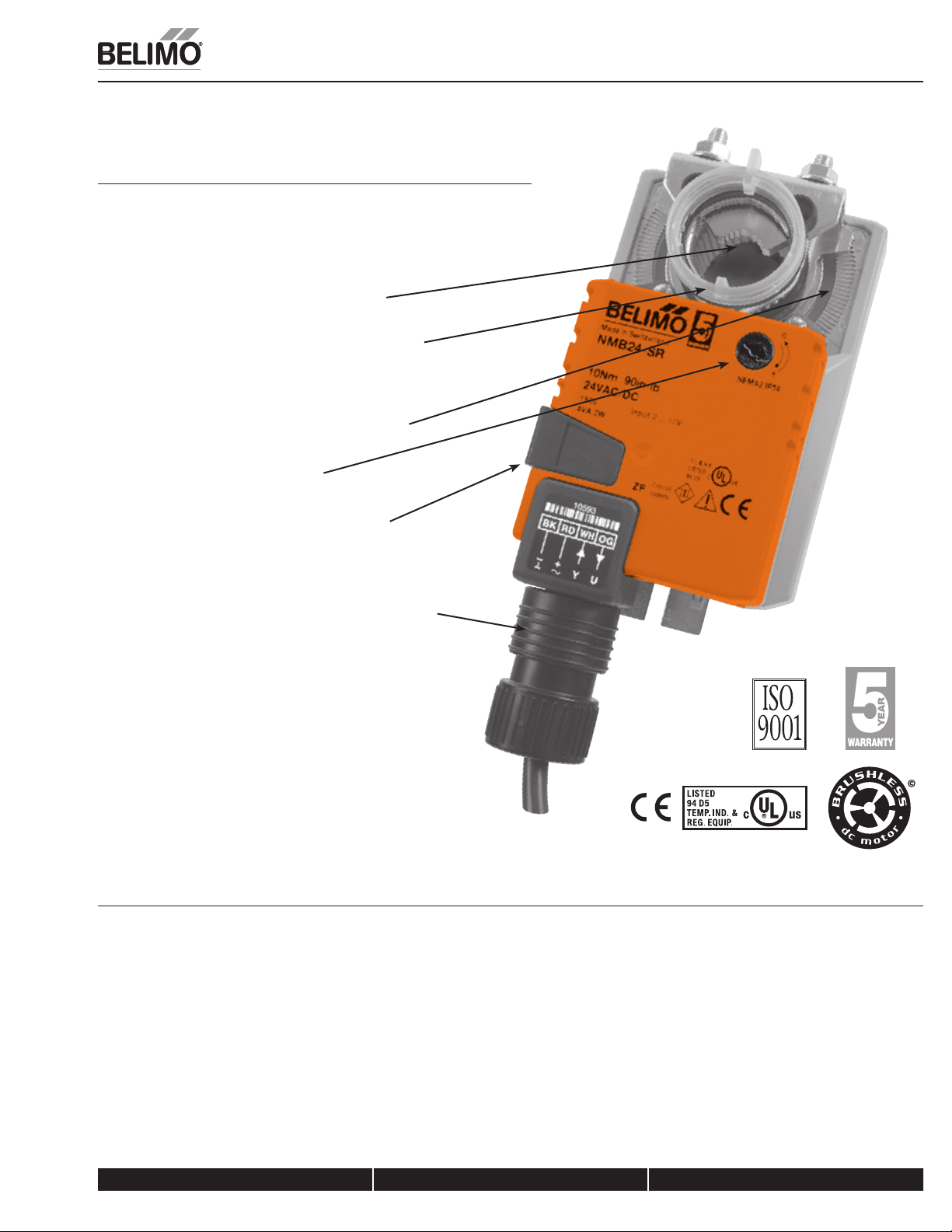
A CLOSER LOOK…
L
Brushless DC Motor for Added Accuracy and
Controllability.
L
Cut Labor Costs with Simple Direct Coupling.
L
Self-Centers on 1/2", 3/4", and 1.05" Jackshafts
with Standard Clamp.
L
Check Damper Position with Clear Position Indicator.
L
Don’t Worry about Actuator Burn-Out; Belimo is Overload
Proof throughout Rotation.
L
Enjoy Added Flexibility with Easy Mechanical Stops
to Adjust Angle of Rotation.
L
Need to Change Control Direction?
Do it easily with a Simple Switch.
NM Series Direct Coupled Actuator
L
Easily Accessible Manual Override Button helps
you Pre-Tension Damper Blades.
L
Auxiliary Switch and Feedback Potentiometer Add-Ons Mount
Directly on Clamp, Includes Conduit Connector.
L
Standard 3ft Plenum Rated Cable and Conduit Connector
Provided on Basic Models.
L
Added Flexibility to Select Clamp, Electrical Connection, and
Running Time to fit your Specific Application with Belimo’s
New Flexible Line of Actuators.
The Belimo Difference
L
Customer Commitment.
Extensive product range. Application assistance.
Same-day shipments. Free technical support. Five year warranty.
K20901 - 01/09 - Subject to change. © Belimo Aircontrols (USA), Inc.
L
Low Installation and Life-Cycle Cost.
Easy installation. Accuracy and repeatability.
Low power consumption. No maintenance.
L
Long Service Life.
Components tested before assembly. Every product tested before shipment.
30+ years direct coupled actuator design.
800-543-9038 USA 866-805-7089 CANADA 203-791-8396 LATIN AMERICA
169
Page 3

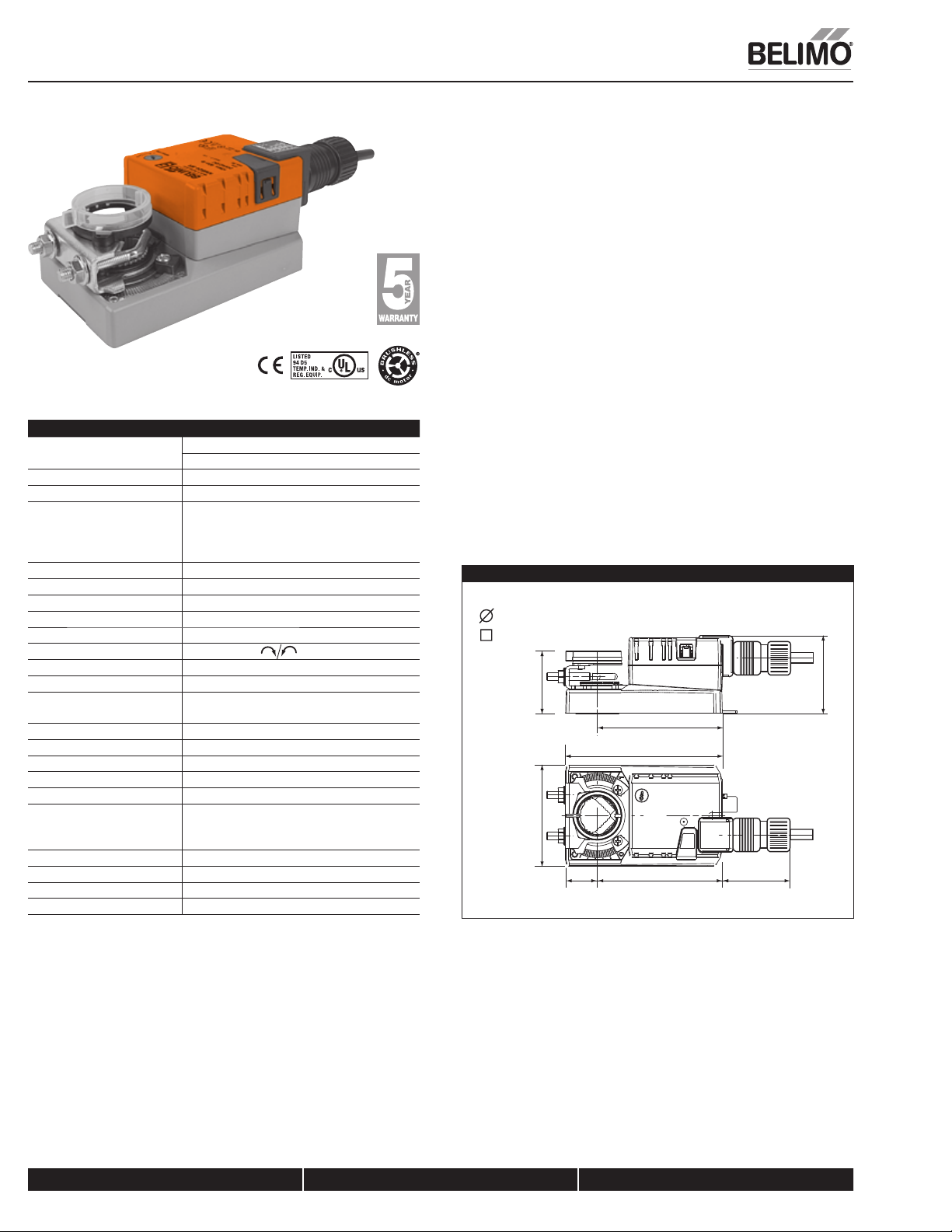
NMB(X)24-3
On/Off-Floating Point Control, Non-Spring Return, Direct Coupled, 24V
Technical Data NMB(X)24-3(-T)
Power Supply 24 VAC ± 20% 50/60 Hz
Power Consumption 2 W (0.2 W)
Transformer Sizing 4 VA (Class 2 power source)
Electrical Connection 18 GA plenum rated cable
Overload Protection electronic throughout 0 to 95° rotation
Control on/off, floating point
Input Impedance 600 7
Angle of Rotation max. 95°, adjust. with mechanical stop
Torque 90 in-lb [10 Nm]
Direction of Rotation reversible with
Position Indication reflective visual indicator (snap-on)
Manual Override external push button
Running Time 95 seconds (default)
Humidity 5 to 95% RH non condensing (EN 60730-1)
Ambient Temperature -22°F to 122°F [-30°C to 50°C]
Storage Temperature -40°F to 176°F [-40°C to 80°C]
Housing NEMA 2, IP54, UL enclosure type 2
Housing Material UL94-5VA
Agency Listings† cULus acc. to UL 60730-1A/-2-14,
Noise Level <45dB(A)
Servicing maintenance free
Quality Standard ISO 9001
Weight 1.7 lbs [0.75 Kg]
24 VDC ± 10%
1/2” conduit connector
Protected NEMA 2 (IP54)
Q 3 ft [1m] Q 10 ft [3m] Q 16 ft [5m]
switch
constant independent of load
CAN/CSA E60730-1:02,
CE acc. to 2004/108/EEC and 2006/95/EC
Torque min. 90 in-lb for control of damper surfaces up to 22 sq ft.
Application
For on/off and floating point control of dampers in HVAC systems. Actuator
sizing should be done in accordance with the damper manufacturer’s
specifications.
The actuator is mounted directly to a damper shaft up to 1.05" in diameter by
means of its universal clamp, 1/2” self-centered default. A crankarm and several
mounting brackets are available for applications where the actuator cannot be
direct coupled to the damper shaft.
Operation
The actuator is not provided with and does not require any limit switches, but is
electronically protected against overload. The anti-rotation strap supplied with
the actuator will prevent lateral movement.
The NMB(X) series provides 95° of rotation and a visual indicator indicates
position of the actuator. When reaching the damper or actuator end position, the
actuator automatically stops. The gears can be manually disengaged with a
button on the actuator cover.
The NMB(X)24-3… actuators use a sensorless Brushless DC motor, which is
controlled by an Application Specific Integrated Circuit (ASIC). The ASIC
monitors and controls the actuator’s rotation and provides a digital rotation
sensing (DRS) function to prevent damage to the actuator in a stall condition.
Power consumption is reduced in holding mode.
Add on auxiliary switches or feedback potentiometers are easily fastened directly
onto the actuator body for signaling and switching functions.
Dimensions (Inches [mm])
1/2” to 1.05” [12.7 to 26.67]
2/5” to 1.05” [10 to 26.67]
2.36” [60]
3.15” [80]
0.98”
[25]
3.66” [93]
4.88” [124]
3.9” [99]
To center of
mounting slot.
2” [50.8]
2.42” [61.4]
D121
NMB(X)24-3-T
Electrical connection screw terminal (for 26 to 14 GA wire)
Q unprotected (NEMA 1/IP20)
Q protected (NEMA 2/IP20)
† Rated Impulse Voltage 800V, Type of action 1, Control Pollution Degree 3.
800-543-9038 USA 866-805-7089 CANADA 203-791-8396 LATIN AMERICA
170
K20901 - 01/09 - Subject to change. © Belimo Aircontrols (USA), Inc.
Page 4

NMB(X)24-3
On/Off-Floating Point Control, Non-Spring Return, Direct Coupled, 24V
Accessories
K-NA Reversible Clamp
ZG-100 Universal Mounting Bracket
ZG-101 Universal Mounting Bracket
ZG-103 Universal Mounting Bracket
ZG-104 Universal Mounting Bracket
ZG-NMA Crankarm Adaptor Kit
AV8-25 Universal Shaft Extension
ZG-NMSA-1 Shaft Adaptor
ZS-T Terminal Cover for NEMA 2
ZS-100 Weather Shield - Steel
ZS-150 Weather Shield - Polycarbonate
Tool-06 8 mm & 10 mm Wrench
S1A, S2A Auxiliary Switch (es)
P370 Shaft Mount Auxiliary Switch
P…A Feedback Potentiometers
NOTE: When using NMX24-3… actuators, only use accessories listed on this page.
Typical Specification
Floating point, on/off control damper actuators shall be electronic direct-coupled
type, which require no crankarm and linkage and be capable of direct mounting to
a shaft up to 1.05” diameter. Actuators shall have Brushless DC motor technology
and be protected from overload at all angles of rotation. Actuators shall have
reversing switch and manual override on the cover. If required, actuators will
be provided with a screw terminal strip for electrical connections (NMX24-3-T).
Run time shall be constant and independent of torque. Actuators shall be cULus
listed, have a 5-year warranty, and be manufactured under ISO 9001 International
Quality Control Standards. Actuators shall be as manufactured by Belimo.
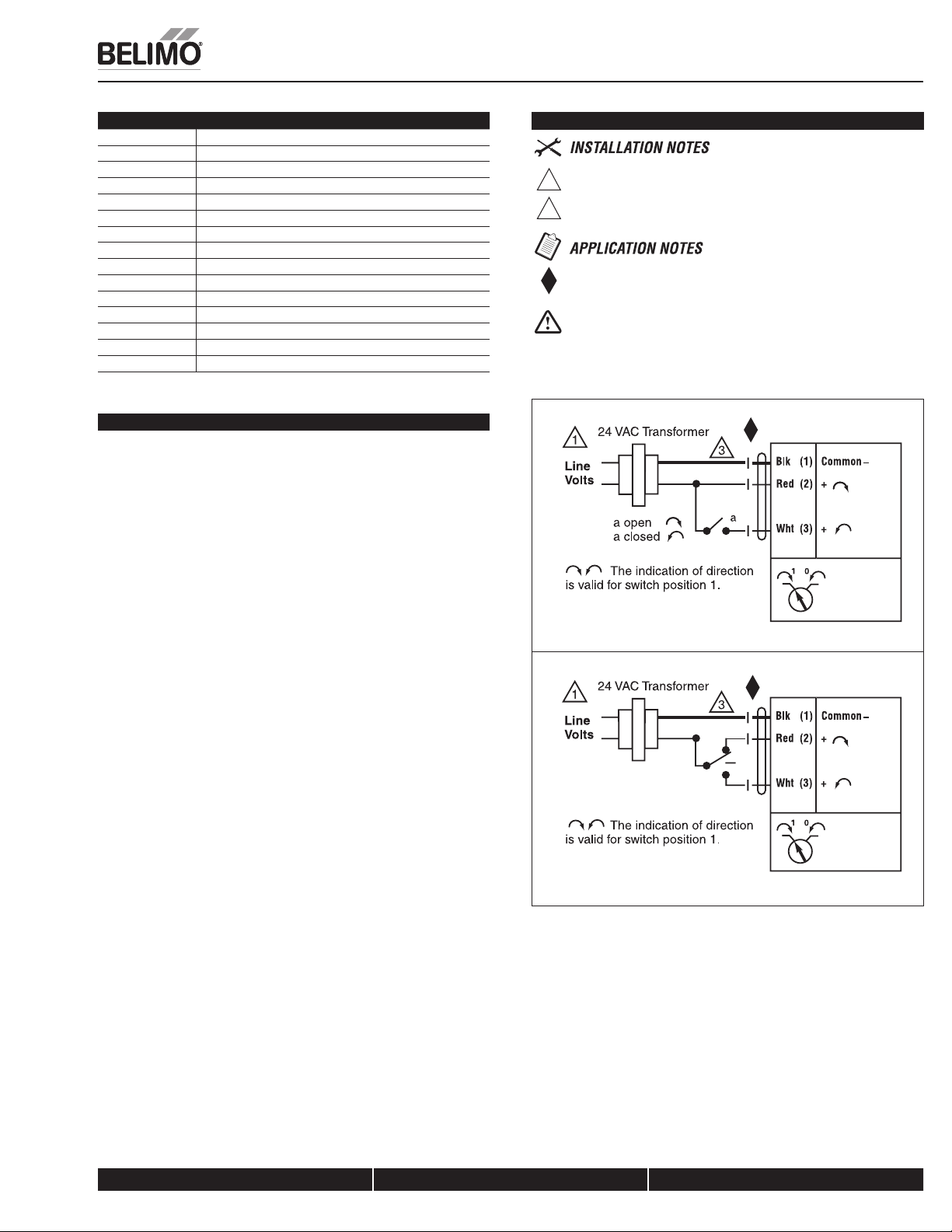
Wiring Diagram
Provide overload protection and disconnect as required.
1
Actuators may also be powered by 24 VDC.
3
Meets cULus or UL and CSA Standard requirements without the
need of an electrical ground connection.
WARNING Live Electrical Components!
During installation, testing, servicing and troubleshooting of this product, it maybe
necessary to work with live electrical components. Have a qualified licensed electrician
or other individual who has been properly trained in handling live electrical components
perform these tasks. Failure to follow all electrical safety precautions when exposed to live
electrical components could result in death or serious injury.
W263_08
K20901 - 01/09 - Subject to change. © Belimo Aircontrols (USA), Inc.
On/Off control
W264_08
Floating Point or On/Off control
800-543-9038 USA 866-805-7089 CANADA 203-791-8396 LATIN AMERICA
171
Page 5

NMCB24-3
On/Off-Floating Point Control, Non-Spring Return, Direct Coupled, 24V
Technical Data NMCB24-3
Power Supply 24 VAC ± 20% 50/60 Hz
Power Consumption 2 W (0.2 W)
Transformer Sizing 4 VA (Class 2 power source)
Electrical Connection 3 ft, 18 GA plenum rated cable
Overload Protection electronic throughout 0 to 95° rotation
Control on/off, floating point
Input Impedance 600 7
Angle of Rotation max. 95°, adjust. with mechanical stop
Torque 90 in-lb [10 Nm]
Direction of Rotation reversible with
Position Indication reflective visual Indicator (snap-on)
Manual Override external push button
Running Time 45 seconds, constant independent of load
Humidity 5 to 95% RH non condensing (EN 60730-1)
Ambient Temperature -22°F to 122°F [-30°C to 50°C]
Storage Temperature -40°F to 176°F [-40°C to 80°C]
Housing NEMA 2, IP54, UL enclosure type 2
Housing Material UL94-5VA
Agency Listings† cULus acc. to UL 60730-1A/-2-14,
Noise Level <45dB(A)
Servicing maintenance free
Quality Standard ISO 9001
Weight 1.7 lbs [0.75 Kg]
† Rated Impulse Voltage 800V, Type of action 1, Control Pollution Degree 3.
24 VDC ± 10%
1/2” conduit connector
Protected NEMA 2 (IP54)
switch
CAN/CSA E60730-1:02,
CE acc. to 2004/108/EEC and 2006/95/EC
Torque min. 90 in-lb for control of damper surfaces up to 22 sq ft.
Application
For on/off and floating point control of dampers in HVAC systems. Actuator
sizing should be done in accordance with the damper manufacturer’s
specifications.
The actuator is mounted directly to a damper shaft up to 1.05" in diameter by
means of its universal clamp, 1/2” self-centered default. A crankarm and several
mounting brackets are available for applications where the actuator cannot be
direct coupled to the damper shaft.
Operation
The actuator is not provided with and does not require any limit switches, but is
electronically protected against overload. The anti-rotation strap supplied with
the actuator will prevent lateral movement.
The NMB series provides 95° of rotation and a visual indicator indicates position
of the actuator. When reaching the damper or actuator end position, the actuator
automatically stops. The gears can be manually disengaged with a button on the
actuator cover.
The NMCB24-3… actuators use a sensorless Brushless DC motor, which is
controlled by an Application Specific Integrated Circuit (ASIC). The ASIC
monitors and controls the actuator’s rotation and provides a digital rotation
sensing (DRS) function to prevent damage to the actuator in a stall condition.
Power consumption is reduced in holding mode.
Add on auxiliary switches or feedback potentiometers are easily fastened directly
onto the actuator body for signaling and switching functions.
Dimensions (Inches [mm])
1/2” to 1.05” [12.7 to 26.67]
2/5” to 1.05” [10 to 26.67]
2.36” [60]
3.15” [80]
0.98”
[25]
3.66” [93]
4.88” [124]
3.9” [99]
To center of
mounting slot.
2” [50.8]
2.42” [61.4]
D121
172
K20901 - 01/09 - Subject to change. © Belimo Aircontrols (USA), Inc.
800-543-9038 USA 866-805-7089 CANADA 203-791-8396 LATIN AMERICA
Page 6
NMCB24-3
On/Off-Floating Point Control, Non-Spring Return, Direct Coupled, 24V
Accessories
K-NA Reversible Clamp
ZG-100 Universal Mounting Bracket
ZG-101 Universal Mounting Bracket
ZG-103 Universal Mounting Bracket
ZG-104 Universal Mounting Bracket
ZG-NMA Crankarm Adaptor Kit
AV8-25 Universal Shaft Extension
ZG-NMSA-1 Shaft Adaptor
ZS-T Terminal Cover for NEMA 2
ZS-100 Weather Shield - Steel
ZS-150 Weather Shield - Polycarbonate
Tool-06 8 mm & 10 mm Wrench
S1A, S2A Auxiliary Switch (es)
P370 Shaft Mount Auxiliary Switch
P…A Feedback Potentiometers
NOTE: When using NMCB24-3… actuators, only use accessories listed on this page.
Typical Specification
Floating point, on/off control damper actuators shall be electronic direct-coupled
type, which require no crankarm and linkage and be capable of direct mounting to
a shaft up to 1.05” diameter. Actuators shall have Brushless DC motor technology
and be protected from overload at all angles of rotation. Actuators shall have
reversing switch and manual override on the cover. Run time shall be constant
and independent of torque. Actuators shall be cULus listed, have a 5-year
warranty, and be manufactured under ISO 9001 International Quality Control
Standards. Actuators shall be as manufactured by Belimo.
Wiring Diagram
Provide overload protection and disconnect as required.
1
Actuators may also be powered by 24 VDC.
3
Meets cULus or UL and CSA Standard requirements without the
need of an electrical ground connection.
WARNING Live Electrical Components!
During installation, testing, servicing and troubleshooting of this product, it maybe
necessary to work with live electrical components. Have a qualified licensed electrician
or other individual who has been properly trained in handling live electrical components
perform these tasks. Failure to follow all electrical safety precautions when exposed to live
electrical components could result in death or serious injury.
W263_08
K20901 - 01/09 - Subject to change. © Belimo Aircontrols (USA), Inc.
On/Off control
W264_08
Floating Point or On/Off control
800-543-9038 USA 866-805-7089 CANADA 203-791-8396 LATIN AMERICA
173
Page 7
NMX120-3
On/Off-Floating Point Control, Non-Spring Return, Direct Coupled, 100 to 240 VAC
Torque min. 90 in-lb for control of damper surfaces up to 22 sq ft.
Application
For on/off and floating point control of dampers in HVAC systems. Actuator
sizing should be done in accordance with the damper manufacturer’s
specifications.
The actuator is mounted directly to a damper shaft up to 1.05" in diameter by
means of its universal clamp, 1/2” self-centered default. A crankarm and several
mounting brackets are available for applications where the actuator cannot be
direct coupled to the damper shaft.
Operation
The actuator is not provided with and does not require any limit switches, but is
electronically protected against overload. The anti-rotation strap supplied with
the actuator will prevent lateral movement.
The NMX series provides 95° of rotation and a visual indicator indicates position
of the actuator. When reaching the damper or actuator end position, the actuator
automatically stops. The gears can be manually disengaged with a button on the
Technical Data NMX120-3
Power Supply nominal 100 to 240 VAC, 50/60 Hz
tolerance 85 to 265 VAC, 50/60 Hz
Power Consumption 3.5 W (0.6 W)
Transformer Sizing 5.5 VA (Class 2 power source)
Electrical Connection 18 GA appliance rated cable
Overload Protection electronic throughout 0 to 95° rotation
Control on/off, floating point
Input Impedance 600 7
Angle of Rotation max. 95°, adjust. with mechanical stop
Torque 90 in-lb [10 Nm]
Direction of Rotation reversible with
Position Indication reflective visual indicator (snap-on)
Manual Override external push button
Running Time
Humidity 5 to 95% RH non condensing (EN 60730-1)
Ambient Temperature -22°F to 122°F [-30°C to 50°C]
Storage Temperature -40°F to 176°F [-40°C to 80°C]
Housing NEMA 2, IP54, UL enclosure type 2
Housing Material UL94-5VA
Agency Listings† cULus acc. to UL 60730-1A/-2-14,
Noise Level <45dB(A)
Servicing maintenance free
Quality Standard ISO 9001
Weight 1.7 lbs [0.75 Kg]
† Rated Impulse Voltage 4kV, Type of action 1, Control Pollution Degree 3.
1/2” conduit connector
Protected NEMA 2 (IP54)
Q 3 ft [1m] Q 10 ft [3m] Q 16 ft [5m]
switch
Q 150 Q 95 Q 60 Q 45 seconds
constant independent of load
CAN/CSA E60730-1:02,
CE acc. to 2004/108/EEC and 2006/95/EC
actuator cover.
The NMX120-3… actuators use a sensorless Brushless DC motor, which is
controlled by an Application Specific Integrated Circuit (ASIC). The ASIC
monitors and controls the actuator’s rotation and provides a digital rotation
sensing (DRS) function to prevent damage to the actuator in a stall condition.
Power consumption is reduced in holding mode.
Add on auxiliary switches or feedback potentiometers are easily fastened directly
onto the actuator body for signaling and switching functions.
Dimensions (Inches [mm])
1/2” to 1.05” [12.7 to 26.67]
2/5” to 1.05” [10 to 26.67]
2.36” [60]3.15” [80]
0.98”
[25]
3.66” [93]
4.88” [124]
3.9” [99]
To center of
mounting slot.
2” [50.8]
D121
2.42” [61.4]
174
K20901 - 01/09 - Subject to change. © Belimo Aircontrols (USA), Inc.
800-543-9038 USA 866-805-7089 CANADA 203-791-8396 LATIN AMERICA
Page 8
NMX120-3
On/Off-Floating Point Control, Non-Spring Return, Direct Coupled, 100 to 240 VAC
Accessories
K-NA Reversible Clamp
ZG-100 Universal Mounting Bracket
ZG-101 Universal Mounting Bracket
ZG-103 Universal Mounting Bracket
ZG-104 Universal Mounting Bracket
ZG-NMA Crankarm Adaptor Kit
AV8-25 Universal Shaft Extension
ZG-NMSA-1 Shaft Adaptor
ZS-100 Weather Shield - Steel
ZS-150 Weather Shield - Polycarbonate
Tool-06 8 mm & 10 mm Wrench
S1A, S2A Auxiliary Switch (es)
P370 Shaft Mount Auxiliary Switch
P…A Feedback Potentiometers
NOTE: When using NMX120-3 actuators, only use accessories listed on this page.
Typical Specification
Floating point, on/off control damper actuators shall be electronic direct-coupled
type, which require no crankarm and linkage and be capable of direct mounting to
a shaft up to 1.05” diameter. Actuators shall have Brushless DC motor technology
and be protected from overload at all angles of rotation. Actuators shall have
reversing switch and manual override on the cover. Run time shall be constant
and independent of torque. Actuators shall be cULus listed, have a 5-year
warranty, and be manufactured under ISO 9001 International Quality Control
Standards. Actuators shall be as manufactured by Belimo.
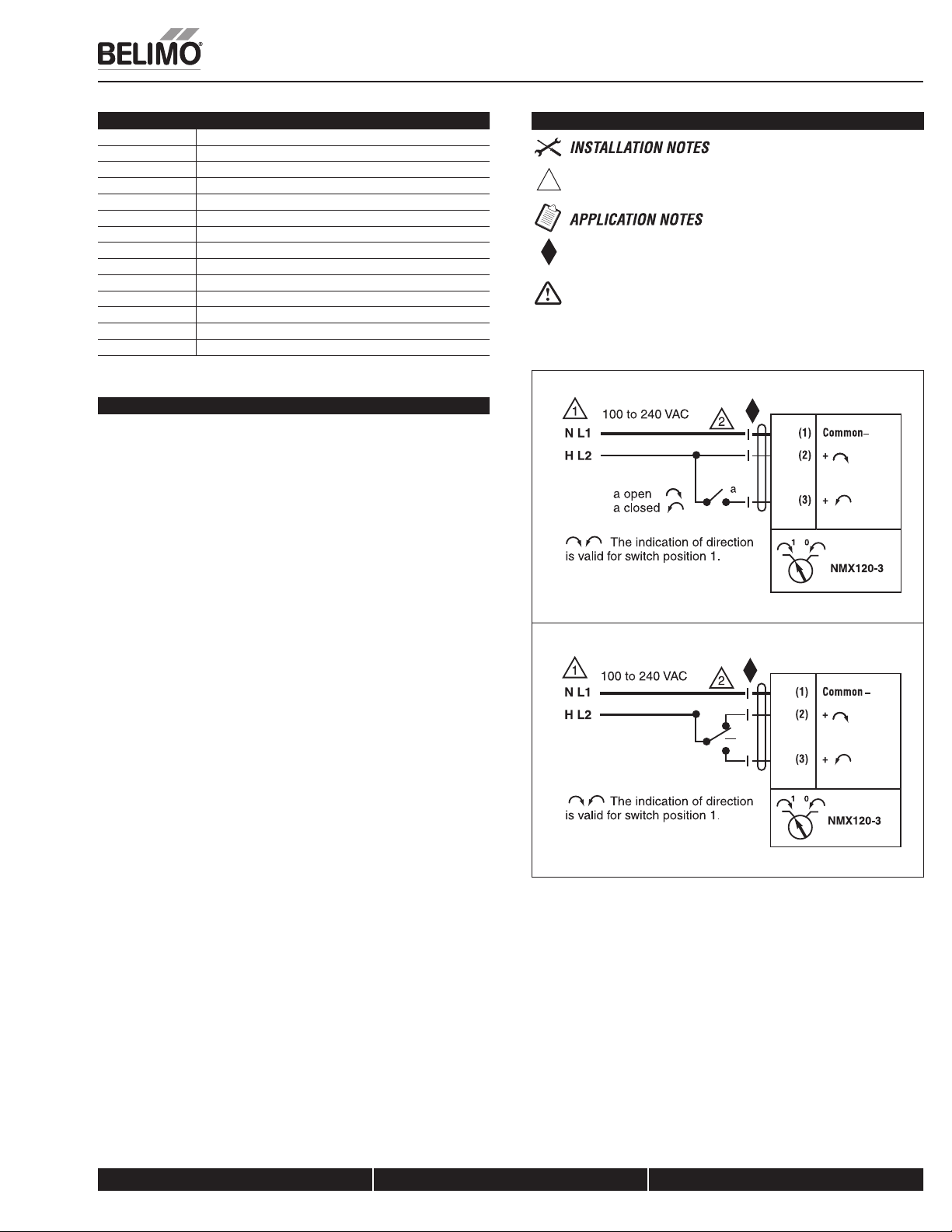
Wiring Diagram
Provide overload protection and disconnect as required.
1
Meets cULus or UL and CSA Standard requirements without the
need of an electrical ground connection.
WARNING Live Electrical Components!
During installation, testing, servicing and troubleshooting of this product, it maybe
necessary to work with live electrical components. Have a qualified licensed electrician
or other individual who has been properly trained in handling live electrical components
perform these tasks. Failure to follow all electrical safety precautions when exposed to live
electrical components could result in death or serious injury.
W369_08
K20901 - 01/09 - Subject to change. © Belimo Aircontrols (USA), Inc.
On/Off control
W370_08
Floating Point or On/Off control
800-543-9038 USA 866-805-7089 CANADA 203-791-8396 LATIN AMERICA
175
Page 9

NMB(X)24-SR
Proportional Control, Non-Spring Return, Direct Coupled, 24V, for 2 to 10 VDC and 4 to 20 mA
Torque min. 90 in-lb for control of damper surfaces up to 22 sq ft.
Application
For proportional modulation of dampers in HVAC systems. Actuator sizing should
be done in accordance with the damper manufacturer’s specifications.
The actuator is mounted directly to a damper shaft up to 1.05" in diameter by
means of its universal clamp, 1/2” self centered default. A crankarm and several
mounting brackets are available for applications where the actuator cannot be
direct coupled to the damper shaft.
The actuator operates in response to a 2 to 10 VDC, or with the addition of a
500 7 resistor, a 4 to 20 mA control input from an electronic controller or
positioner. A 2 to 10 VDC feedback signal is provided for position indication or
master-slave applications.
Operation
The actuator is not provided with and does not require any limit switches, but is
electronically protected against overload. The anti-rotation strap supplied with the
actuator will prevent lateral movement.
Technical Data NMB(X)24-SR(-T)
Power Supply 24 VAC ± 20% 50/60 Hz
Power Consumption 2.5 W (0.4 W)
Transformer Sizing 5 VA (Class 2 power source)
Electrical Connection 18 GA plenum rated cable
Overload Protection electronic throughout 0 to 95° rotation
Operating Range Y 2 to 10 VDC, 4 to 20 mA
Input Impedance 100 k7 (0.1 mA), 500 7
Angle of Rotation max. 95°, adjust. with mechanical stop
Torque 90 in-lb [10 Nm]
Direction of Rotation
Position Indication reflective visual indicator (snap-on)
Manual Override external push button
Running Time
Humidity 5 to 95% RH non condensing (EN 60730-1)
Ambient Temperature -22°F to 122°F [-30°C to 50°C]
Storage Temperature -40°F to 176°F [-40°C to 80°C]
Housing NEMA 2, IP54, UL enclosure type 2
Housing Material UL94-5VA
Agency Listings† cULus acc. to UL 60730-1A/-2-14,
Noise Level <45dB(A)
Servicing maintenance free
Quality Standard ISO 9001
Weight 1.7 lbs [0.75 Kg]
24 VDC ± 10%
1/2” conduit connector
Protected NEMA 2 (IP54)
Q 3 ft [1m] Q 10 ft [3m] Q 16 ft [5m]
reversible with
switch
Actuator will move:
=CCW with decreasing control signal (10 to 2V)
=CW with decreasing control signal (10 to 2V)
Q 150 Q 95 Q 60 Q 45 seconds
constant independent of load
CAN/CSA E60730-1:02,
CE acc. to 2004/108/EEC and 2006/95/EC
The NMB(X) series provides 95° of rotation and a visual indicator indicates
position of the actuator. When reaching the damper or actuator end position, the
actuator automatically stops. The gears can be manually disengaged with a
button on the actuator cover.
The NMB(X)24-SR… actuators use a sensorless Brushless DC motor, which is
controlled by an Application Specific Integrated Circuit (ASIC). The ASIC
monitors and controls the actuator’s rotation and provides a digital rotation
sensing (DRS) function to prevent damage to the actuator in a stall condition.
Power consumption is reduced in holding mode.
Add on auxiliary switches or feedback potentiometers are easily fastened directly
onto the actuator body for signaling and switching functions.
Dimensions (Inches [mm])
1/2” to 1.05” [12.7 to 26.67]
2/5” to 1.05” [10 to 26.67]
2.36” [60]
3.15” [80]
0.98”
[25]
3.66” [93]
4.88” [124]
3.9” [99]
To center of
mounting slot.
2” [50.8]
D121
2.42” [61.4]
NMB(X)24-SR-T
Electrical connection screw terminal (for 26 to 14 GA wire)
Q unprotected (NEMA 1/IP20)
Q protected (NEMA 2/IP20)
† Rated Impulse Voltage 800V, Type of action 1, Control Pollution Degree 3.
800-543-9038 USA 866-805-7089 CANADA 203-791-8396 LATIN AMERICA
176
K20901 - 01/09 - Subject to change. © Belimo Aircontrols (USA), Inc.
Page 10

NMB(X)24-SR
Proportional Control, Non-Spring Return, Direct Coupled, 24V, for 2 to 10 VDC and 4 to 20 mA
Accessories
K-NA Reversible Clamp
ZG-100 Universal Mounting Bracket
ZG-101 Universal Mounting Bracket
ZG-103 Universal Mounting Bracket
ZG-104 Universal Mounting Bracket
ZG-NMA Crankarm Adaptor Kit
AV8-25 Universal Shaft Extension
ZG-NMSA-1 Shaft Adaptor
ZS-T Terminal Cover for NEMA 2
ZS-100 Weather Shield - Steel
ZS-150 Weather Shield - Polycarbonate
Tool-06 8 mm & 10 mm Wrench
S1A, S2A Auxiliary Switch (es)
P370 Shaft Mount Auxiliary Switch
P…A Feedback Potentiometers
SGA24 Min positioners in NEMA 4 housing
SGF24 Min positioners for flush panel mounting
PTA-250 Pulse Width Modulation Interface
IRM-100 Input Rescaling Module
ADS-100 Analog to Digital Switch
ZG-R01 Resistor for 4 to 20 mA Conversion
NSV24 US Battery Back-Up Module
ZG-X40 Transformer
NOTE: When using NMB(X)24-SR… actuators, only use accessories listed on this page.
Typical Specification
Proportional control damper actuators shall be electronic direct-coupled type,
which require no crankarm and linkage and be capable of direct mounting to a
shaft up to 1.05” diameter. Actuators must provide proportional damper control
in response to a 2 to 10 VDC or, with the addition of a 500 7 resistor, a 4 to
20 mA control input from an electronic controller or positioner. Actuators shall
have Brushless DC motor technology and be protected from overload at all
angles of rotation. Actuators shall have reversing switch and manual override
on the cover. If required, actuator will be provided with screw terminal strip
for electrical connections (NMX24-SR-T). Run time shall be constant and
independent of torque. A 2 to 10 VDC feedback signal shall be provided for
position indication. Actuators shall be cULus listed, have a 5-year warranty,
and be manufactured under ISO 9001 International Quality Control Standards.
Actuators shall be as manufactured by Belimo.
Wiring Diagram
Provide overload protection and disconnect as required.
1
CAUTION Equipment damage!
2
Actuators may be connected in parallel.
Power consumption and input impedance must be observed.
Actuators may also be powered by 24 VDC.
3
Only connect common to neg. (–) leg of control circuits.
5
The ZG-R01 500 7 resistor converts the 4 to 20 mA control signal to
2 to 10 VDC, up to 2 actuators may be connected in parallel.
WARNING Live Electrical Components!
During installation, testing, servicing and troubleshooting of this product, it maybe
necessary to work with live electrical components. Have a qualified licensed electrician
or other individual who has been properly trained in handling live electrical components
perform these tasks. Failure to follow all electrical safety precautions when exposed to live
electrical components could result in death or serious injury.
2 to 10 VDC control
W261_08
W261_08
K20901 - 01/09 - Subject to change. © Belimo Aircontrols (USA), Inc.
4 to 20 mA control
800-543-9038 USA 866-805-7089 CANADA 203-791-8396 LATIN AMERICA
177
Page 11

NMCB24-SR
Proportional Control, Non-Spring Return, Direct Coupled, 24V, for 2 to 10 VDC and 4 to 20 mA
Torque min. 90 in-lb for control of damper surfaces up to 22 sq ft.
Application
For proportional modulation of dampers in HVAC systems. Actuator sizing should
be done in accordance with the damper manufacturer’s specifications.
The actuator is mounted directly to a damper shaft up to 1.05" in diameter by
means of its universal clamp, 1/2” self centered default. A crankarm and several
mounting brackets are available for applications where the actuator cannot be
direct coupled to the damper shaft.
The actuator operates in response to a 2 to 10 VDC, or with the addition of a
500 7 resistor, a 4 to 20 mA control input from an electronic controller or
positioner. A 2 to 10 VDC feedback signal is provided for position indication or
master-slave applications.
Operation
The actuator is not provided with and does not require any limit switches, but is
electronically protected against overload. The anti-rotation strap supplied with the
actuator will prevent lateral movement.
Technical Data NMCB24-SR
Power Supply 24 VAC ± 20% 50/60 Hz
Power Consumption 2.5 W (.4 W)
Transformer Sizing 5 VA (Class 2 power source)
Electrical Connection 3ft, 18 GA plenum rated cable
Overload Protection electronic throughout 0 to 95° rotation
Operating Range Y 2 to 10 VDC, 4 to 20 mA
Input Impedance 100 k7 (0.1 mA), 500 7
Feedback Output U 2 to 10 VDC (max 0.5 mA)
Angle of Rotation max. 95°, adjust. with mechanical stop
Torque 90 in-lb [10 Nm]
Direction of Rotation
Position Indication reflective visual indicator (snap-on)
Manual Override external push button
Running Time 45 seconds, constant independent of load
Humidity 5 to 95% RH non condensing (EN 60730-1)
Ambient Temperature -22°F to 122°F [-30°C to 50°C]
Storage Temperature -40°F to 176°F [-40°C to 80°C]
Housing NEMA 2, IP54, UL enclosure type 2
Housing Material UL94-5VA
Agency Listings† cULus acc. to UL 60730-1A/-2-14,
Noise Level <45dB(A)
Servicing maintenance free
Quality Standard ISO 9001
Weight 1.7 lbs [0.75 Kg]
† Rated Impulse Voltage 800V, Type of action 1, Control Pollution Degree 3.
24 VDC ± 10%
1/2” conduit connector
Protected NEMA 2 (IP54)
reversible with
switch
Actuator will move:
=CCW with decreasing control signal (10 to 2V)
=CW with decreasing control signal (10 to 2V)
CAN/CSA E60730-1:02,
CE acc. to 2004/108/EEC and 2006/95/EC
The NM series provides 95° of rotation and a visual indicator indicates position
of the actuator. When reaching the damper or actuator end position, the actuator
automatically stops. The gears can be manually disengaged with a button on the
actuator cover.
The NMCB24-SR… actuators use a sensorless Brushless DC motor, which is
controlled by an Application Specific Integrated Circuit (ASIC). The ASIC
monitors and controls the actuator’s rotation and provides a digital rotation
sensing (DRS) function to prevent damage to the actuator in a stall condition.
Power consumption is reduced in holding mode.
Add on auxiliary switches or feedback potentiometers are easily fastened directly
onto the actuator body for signaling and switching functions.
Dimensions (Inches [mm])
1/2” to 1.05” [12.7 to 26.67]
2/5” to 1.05” [10 to 26.67]
2.36” [60]
3.15” [80]
0.98”
[25]
3.66” [93]
4.88” [124]
3.9” [99]
To center of
mounting slot.
2” [50.8]
D121
2.42” [61.4]
178
K20901 - 01/09 - Subject to change. © Belimo Aircontrols (USA), Inc.
800-543-9038 USA 866-805-7089 CANADA 203-791-8396 LATIN AMERICA
Page 12

NMCB24-SR
Proportional Control, Non-Spring Return, Direct Coupled, 24V, for 2 to 10 VDC and 4 to 20 mA
Accessories
K-NA Reversible Clamp
ZG-100 Universal Mounting Bracket
ZG-101 Universal Mounting Bracket
ZG-103 Universal Mounting Bracket
ZG-104 Universal Mounting Bracket
ZG-NMA Crankarm Adaptor Kit
AV8-25 Universal Shaft Extension
ZG-NMSA-1 Shaft Adaptor
ZS-T Terminal Cover for NEMA 2/IP54
ZS-100 Weather Shield - Steel
ZS-150 Weather Shield - Polycarbonate
Tool-06 8 mm & 10 mm Wrench
S1A, S2A Auxiliary Switch (es)
P370 Shaft Mount Auxiliary Switch
P…A Feedback Potentiometers
SGA24 Min positioners in NEMA 4 housing
SGF24 Min positioners for flush panel mounting
PTA-250 Pulse Width Modulation Interface
IRM-100 Input Rescaling Module
ADS-100 Analog to Digital Switch
ZG-R01 Resistor for 4 to 20 mA Conversion
NSV24 US Battery Back-Up Module
ZG-X40 Transformer
NOTE: When using NMCB24-SR… actuators, only use accessories listed on this page.
Typical Specification
Proportional control damper actuators shall be electronic direct-coupled type,
which require no crankarm and linkage and be capable of direct mounting to a
shaft up to 1.05” diameter. Actuators must provide proportional damper control
in response to a 2 to 10 VDC or, with the addition of a 500 7 resistor, a 4 to 20
mA control input from an electronic controller or positioner. Actuators shall have
Brushless DC motor technology and be protected from overload at all angles of
rotation. Actuators shall have reversing switch and manual override on the cover.
Run time shall be constant and independent of torque. A 2 to 10 VDC feedback
signal shall be provided for position indication. Actuators shall be cULus listed,
have a 5-year warranty, and be manufactured under ISO 9001 International
Quality Control Standards. Actuators shall be as manufactured by Belimo.
Wiring Diagram
Provide overload protection and disconnect as required.
1
CAUTION Equipment damage!
2
Actuators may be connected in parallel.
Power consumption and input impedance must be observed.
Actuators may also be powered by 24 VDC.
3
Only connect common to neg. (–) leg of control circuits.
5
The ZG-R01 500 7 resistor converts the 4 to 20 mA control signal to
2 to 10 VDC, up to 2 actuators may be connected in parallel.
WARNING Live Electrical Components!
During installation, testing, servicing and troubleshooting of this product, it maybe
necessary to work with live electrical components. Have a qualified licensed electrician
or other individual who has been properly trained in handling live electrical components
perform these tasks. Failure to follow all electrical safety precautions when exposed to live
electrical components could result in death or serious injury.
2 to 10 VDC control
W261_08
K20901 - 01/09 - Subject to change. © Belimo Aircontrols (USA), Inc.
W261_08
4 to 20 mA control
800-543-9038 USA 866-805-7089 CANADA 203-791-8396 LATIN AMERICA
179
Page 13

NMX120-SR
Proportional Control, Non-Spring Return, Direct Coupled, 100 to 240 VAC, for 2 to 10 VDC and 4 to 20 mA
Torque min. 90 in-lb for control of damper surfaces up to 22 sq ft.
Application
For proportional modulation of dampers in HVAC systems. Actuator sizing should
be done in accordance with the damper manufacturer’s specifications.
The actuator is mounted directly to a damper shaft up to 1.05" in diameter by
means of its universal clamp, 1/2” self centered default. A crankarm and several
mounting brackets are available for applications where the actuator cannot be
direct coupled to the damper shaft.
The actuator operates in response to a 2 to 10 VDC, or with the addition of a
500 7 resistor, a 4 to 20 mA control input from an electronic controller or
positioner. A 2 to 10 VDC feedback signal is provided for position indication or
master-slave applications.
Operation
The actuator is not provided with and does not require any limit switches, but is
electronically protected against overload. The anti-rotation strap supplied with the
actuator will prevent lateral movement.
Technical Data NMX120-SR
Power Supply nominal 100 to 240 VAC, 50/60 Hz
tolerance 85 to 265 VAC, 50/60 Hz
Power Consumption 3.5 W (1 W)
Transformer Sizing 6.5 VA (Class 2 power source)
Electrical Connection 18 GA appliance rated cable
Overload Protection electronic throughout 0 to 95° rotation
Operating Range Y 2 to 10 VDC, 4 to 20 mA
Input Impedance 100 k7 (0.1 mA), 500 7
Feedback Output U 2 to 10 VDC (max 0.5 mA)
Angle of Rotation max. 95°, adjust. with mechanical stop
Torque 90 in-lb [10 Nm]
Direction of Rotation
Position Indication reflective visual indicator (snap-on)
Manual Override external push button
Running Time
Humidity 5 to 95% RH non condensing (EN 60730-1)
Ambient Temperature -22°F to 122°F [-30°C to 50°C]
Storage Temperature -40°F to 176°F [-40°C to 80°C]
Housing NEMA 2, IP54, UL enclosure type 2
Housing Material UL94-5VA
Agency Listings† cULus acc. to UL 60730-1A/-2-14,
Noise Level <45dB(A)
Servicing maintenance free
Quality Standard ISO 9001
Weight 1.7 lbs [0.75 Kg]
† Rated Impulse Voltage 4kV, Type of action 1, Control Pollution Degree 3.
1/2” conduit connector
Protected NEMA 2 (IP54)
Q 3 ft [1m] Q 10 ft [3m] Q 16 ft [5m]
reversible with
switch
Actuator will move:
=CCW with decreasing control signal (10 to 2V)
=CW with decreasing control signal (10 to 2V)
Q 150 Q 95 Q 60 Q 45 seconds
constant independent of load
CAN/CSA E60730-1:02,
CE acc. to 2004/108/EEC and 2006/95/EC
The NMX series provides 95° of rotation and a visual indicator indicates position
of the actuator. When reaching the damper or actuator end position, the actuator
automatically stops. The gears can be manually disengaged with a button on the
actuator cover.
The NMX120-SR actuators use a sensorless Brushless DC motor, which is
controlled by an Application Specific Integrated Circuit (ASIC). The ASIC
monitors and controls the actuator’s rotation and provides a digital rotation
sensing (DRS) function to prevent damage to the actuator in a stall condition.
Power consumption is reduced in holding mode.
Add on auxiliary switches or feedback potentiometers are easily fastened directly
onto the actuator body for signaling and switching functions.
Dimensions (Inches [mm])
1/2” to 1.05” [12.7 to 26.67]
2/5” to 1.05” [10 to 26.67]
2.36” [60]
3.66” [93]
4.88” [124]
3.15” [80]
0.98”
[25]
3.9” [99]
To center of
mounting slot.
2” [50.8]
D121
2.42” [61.4]
K20901 - 01/09 - Subject to change. © Belimo Aircontrols (USA), Inc.
180
800-543-9038 USA 866-805-7089 CANADA 203-791-8396 LATIN AMERICA
Page 14

NMX120-SR
Proportional Control, Non-Spring Return, Direct Coupled, 100 to 240 VAC, for 2 to 10 VDC and 4 to 20 mA
Accessories
K-NA Reversible Clamp
ZG-100 Universal Mounting Bracket
ZG-101 Universal Mounting Bracket
ZG-103 Universal Mounting Bracket
ZG-104 Universal Mounting Bracket
ZG-NMA Crankarm Adaptor Kit
AV8-25 Universal Shaft Extension
ZG-NMSA-1 Shaft Adaptor
ZS-100 Weather Shield - Steel
ZS-150 Weather Shield - Polycarbonate
Tool-06 8 mm & 10 mm Wrench
S1A, S2A Auxiliary Switch (es)
P370 Shaft Mount Auxiliary Switch
P…A Feedback Potentiometers
SGA24 Min positioners in NEMA 4 housing
SGF24 Min positioners for flush panel mounting
PTA-250 Pulse Width Modulation Interface
IRM-100 Input Rescaling Module
ADS-100 Analog to Digital Switch
ZG-R01 Resistor for 4 to 20 mA Conversion
NSV24 US Battery Back-Up Module
NOTE: When using NMX120-SR actuators, only use accessories listed on this page.
Typical Specification
Proportional control damper actuators shall be electronic direct-coupled type,
which require no crankarm and linkage and be capable of direct mounting to a
shaft up to 1.05” diameter. Actuators must provide proportional damper control
in response to a 2 to 10 VDC or, with the addition of a 500 7 resistor, a 4 to 20
mA control input from an electronic controller or positioner. Actuators shall have
Brushless DC motor technology and be protected from overload at all angles of
rotation. Actuators shall have reversing switch and manual override on the cover.
Run time shall be constant and independent of torque. A 2 to 10 VDC feedback
signal shall be provided for position indication. Actuators shall be cULus listed,
have a 5-year warranty, and be manufactured under ISO 9001 International
Quality Control Standards. Actuators shall be as manufactured by Belimo.
Wiring Diagram
Provide overload protection and disconnect as required.
1
CAUTION Equipment damage!
2
Actuators may be connected in parallel.
Power consumption and input impedance must be observed.
Only connect common to neg. (–) leg of control circuits.
5
Meets cULus or UL and CSA Standard requirements without the
need of an electrical ground connection.
The ZG-R01 500 7 resistor converts the 4 to 20 mA control signal to
2 to 10 VDC, up to 2 actuators may be connected in parallel.
WARNING Live Electrical Components!
During installation, testing, servicing and troubleshooting of this product, it maybe
necessary to work with live electrical components. Have a qualified licensed electrician
or other individual who has been properly trained in handling live electrical components
perform these tasks. Failure to follow all electrical safety precautions when exposed to live
electrical components could result in death or serious injury.
W371_08
K20901 - 01/09 - Subject to change. © Belimo Aircontrols (USA), Inc.
2 to 10 VDC and 4 to 20 mA control
800-543-9038 USA 866-805-7089 CANADA 203-791-8396 LATIN AMERICA
181
Page 15

NMB(X)24-MFT
Proportional Control, Non-Spring Return, Direct Coupled, 24V, Multi-Function Technology
Torque min. 90 in-lb for control of damper surfaces up to 22 sq ft.
Application
For proportional modulation of dampers in HVAC systems. Actuator sizing should
be done in accordance with the damper manufacturer’s specifications.
The actuator is mounted directly to a damper shaft up to 1.05" in diameter by
means of its universal clamp, 1/2” self centered default. A crankarm and several
mounting brackets are available for applications where the actuator cannot be
direct coupled to the damper shaft.
The default parameters for 2 to 10 VDC applications of the …MFT actuator are
assigned during manufacturing. If necessary, custom versions of the actuators
can be ordered. The parameters can be changed by two means: pre-set and
custom configurations from Belimo or on-site configurations using the Belimo
PC-Tool software.
Operation
The actuator is not provided with and does not require any limit switches, but is
electronically protected against overload. The anti-rotation strap supplied with the
Technical Data NMB(X)24-MFT
Power Supply 24 VAC ± 20% 50/60 Hz
Power Consumption 3.5 W (1.3 W)
Transformer Sizing 6 VA (Class 2 power source)
Electrical Connection 18 GA plenum rated cable
Overload Protection electronic throughout 0 to 95° rotation
Operating Range Y 2 to 10 VDC, 4 to 20 mA (default)
Input Impedance 100 k7 (0.1 mA), 500 7
Feedback Output U 2 to 10 VDC, 0.5 mA max, VDC Variable
Angle of Rotation max. 95°, adjust. with mechanical stop
Torque 90 in-lb [10 Nm]
Direction of Rotation reversible with
Position Indication reflective visual indicator (snap-on)
Manual Override external push button
Running Time 150 seconds (default)
Humidity 5 to 95% RH non condensing (EN 60730-1)
Ambient Temperature -22°F to 122°F [-30°C to 50°C]
Storage Temperature -40°F to 176°F [-40°C to 80°C]
Housing NEMA 2, IP54, UL enclosure type 2
Housing Material UL94-5VA
Agency Listings† cULus acc. to UL 60730-1A/-2-14,
Noise Level <45dB(A)
Servicing maintenance free
Quality Standard ISO 9001
Weight 2.1 lbs [0.95 Kg]
† Rated Impulse Voltage 800V, Type of action 1, Control Pollution Degree 3.
24 VDC ± 10%
1/2” conduit connector
Protected NEMA 2 (IP54)
Q 3 ft [1m] Q 10 ft [3m] Q 16 ft [5m]
Variable (VDC, PWM, Floating Point, On/Off)
1500 7 (PWM, Floating Point, On/Off)
electronically variable
switch
Variable (45 to 170 secs)
CAN/CSA E60730-1:02,
CE acc. to 2004/108/EEC and 2006/95/EC
actuator will prevent lateral movement.
The NMB(X) series provides 95° of rotation and a visual indicator indicates
position of the actuator. When reaching the damper or actuator end position, the
actuator automatically stops. The gears can be manually disengaged with a
button on the actuator cover.
The NMB(X)24-MFT actuators use a Brushless DC motor, which is controlled by
an Application Specific Integrated Circuit (ASIC). The ASIC monitors and controls
the actuator’s rotation and provides a digital rotation sensing (DRS) function to
prevent damage to the actuator in a stall condition.Power consumption is
reduced in holding mode.
Add on auxiliary switches or feedback potentiometers are easily fastened directly
onto the actuator body for signaling and switching functions.
Dimensions (Inches [mm])
1/2” to 1.05” [12.7 to 26.67]
2/5” to 1.05” [10 to 26.67]
2.36” [60]
3.15” [80]
0.98”
[25]
®
3.66” [93]
4.88” [124]
3.9” [99]
To center of
mounting slot.
2” [50.8]
D121
2.42” [61.4]
K20901 - 01/09 - Subject to change. © Belimo Aircontrols (USA), Inc.
182
800-543-9038 USA 866-805-7089 CANADA 203-791-8396 LATIN AMERICA
Page 16

Proportional Control, Non-Spring Return, Direct Coupled, 24V, Multi-Function Technology
Accessories
K-NA Reversible Clamp
ZG-100 Universal Mounting Bracket
ZG-101 Universal Mounting Bracket
ZG-103 Universal Mounting Bracket
ZG-104 Universal Mounting Bracket
ZG-NMA Crankarm Adaptor Kit
AV8-25 Universal Shaft Extension
ZG-NMSA-1 Shaft Adaptor
ZS-100 Weather Shield - Steel
ZS-150 Weather Shield - Polycarbonate
Tool-06 8 mm & 10 mm Wrench
S1A, S2A Auxiliary Switch (es)
P370 Shaft Mount Auxiliary Switch
P…A Feedback Potentiometers
SGA24 Min positioners in NEMA 4 housing
SGF24 Min positioners for flush panel mounting
ADS-100 Analog to Digital Switch
ZG-R01 Resistor for 4 to 20 mA Conversion
NSV24 US Battery Back-Up Module
ZG-X40 Transformer
NOTE: When using NMB(X)24-MFT actuators, only use accessories listed on this page.
NMB(X)24-MFT
®
W399_08
VDC/4-20 mA
W399_08
Typical Specification
Proportional control damper actuators shall be electronic direct-coupled type,
which require no crankarm and linkage and be capable of direct mounting to a
shaft up to 1.05” diameter. Actuators must provide proportional damper control
in response to a 2 to 10 VDC or, with the addition of a 500 7 resistor, a 4 to 20
mA control input from an electronic controller or positioner. Actuators shall have
Brushless DC motor technology and be protected from overload at all angles of
rotation. Actuators shall have reversing switch and manual override on the cover.
Run time shall be constant and independent of torque. Actuators shall be cULus
listed, have a 5-year warranty, and be manufactured under ISO 9001 International
Quality Control Standards. Actuators shall be as manufactured by Belimo.
Wiring Diagrams
Provide overload protection and disconnect as required.
1
CAUTION Equipment damage!
2
Actuators may be connected in parallel if not mechanically mounted to the
same shaft. Power consumption and input impedance must be observed.
Actuators may also be powered by 24 VDC.
3
Position feedback cannot be used with Triac sink controller.
4
The actuator internal common reference is not compatible.
Control signal may be pulsed from either the Hot (source)
5
or the Common (sink) 24 VAC line.
Contact closures A & B also can be triacs.
8
A & B should both be closed for triac source and open for triac sink.
For triac sink the common connection from the actuator
9
must be connected to the hot connection of the controller.
K20901 - 01/09 - Subject to change. © Belimo Aircontrols (USA), Inc.
PWM
W399_08
On/Off control
W399_08
Floating Point control
The ZG-R01 500 7 resistor may be used.
WARNING Live Electrical Components!
During installation, testing, servicing and troubleshooting of this product, it maybe
necessary to work with live electrical components. Have a qualified licensed electrician
or other individual who has been properly trained in handling live electrical components
perform these tasks. Failure to follow all electrical safety precautions when exposed to live
electrical components could result in death or serious injury.
800-543-9038 USA 866-805-7089 CANADA 203-791-8396 LATIN AMERICA
183
Page 17

NMCX24-MFT
Proportional Control, Non-Spring Return, Direct Coupled, 24V, Multi-Function Technology
Torque min. 90 in-lb for control of damper surfaces up to 22 sq ft.
Application
For proportional modulation of dampers in HVAC systems. Actuator sizing should
be done in accordance with the damper manufacturer’s specifications.
The actuator is mounted directly to a damper shaft up to 1.05" in diameter by
means of its universal clamp, 1/2” self centered default. A crankarm and several
mounting brackets are available for applications where the actuator cannot be
direct coupled to the damper shaft.
The default parameters for 2 to 10 VDC applications of the …MFT actuator are
assigned during manufacturing. If necessary, custom versions of the actuators
can be ordered. The parameters can be changed by two means: pre-set and
custom configurations from Belimo or on-site configurations using the Belimo
PC-Tool software.
Operation
The actuator is not provided with and does not require any limit switches, but is
electronically protected against overload. The anti-rotation strap supplied with the
Technical Data NMCX24-MFT
Power Supply 24 VAC ± 20% 50/60 Hz
Power Consumption 3.5 W (1.25 W)
Transformer Sizing 5.5 VA (Class 2 power source)
Electrical Connection 18 GA plenum rated cable
Overload Protection electronic throughout 0 to 95° rotation
Operating Range Y 2 to 10 VDC, 4 to 20 mA (default)
Input Impedance 100 k7 (0.1 mA), 500 7
Feedback Output U 2 to 10 VDC, 0.5 mA max, VDC Variable
Angle of Rotation max. 95°, adjust. with mechanical stop
Torque 90 in-lb [10 Nm]
Direction of Rotation reversible with
Position Indication reflective visual indicator (snap-on)
Manual Override external push button
Running Time 45 seconds (default)
Humidity 5 to 95% RH non condensing (EN 60730-1)
Ambient Temperature -22°F to 122°F [-30°C to 50°C]
Storage Temperature -40°F to 176°F [-40°C to 80°C]
Housing NEMA 2, IP54, UL enclosure type 2
Housing Material UL94-5VA
Agency Listings† cULus acc. to UL 60730-1A/-2-14,
Noise Level <45dB(A)
Servicing maintenance free
Quality Standard ISO 9001
Weight 2.1 lbs [0.95 Kg]
† Rated Impulse Voltage 800V, Type of action 1, Control Pollution Degree 3.
24 VDC ± 10%
1/2” conduit connector
Protected NEMA 2 (IP54)
Q 3 ft [1m] Q 10 ft [3m] Q 16 ft [5m]
Variable (VDC, PWM, Floating Point, On/Off)
1500 7 (PWM, Floating Point, On/Off)
electronically variable
switch
Variable (20 to 60 secs)
CAN/CSA E60730-1:02,
CE acc. to 2004/108/EEC and 2006/95/EC
actuator will prevent lateral movement.
The NMCX series provides 95° of rotation and a visual indicator indicates
position of the actuator. When reaching the damper or actuator end position, the
actuator automatically stops. The gears can be manually disengaged with a
button on the actuator cover.
The NMCX24-MFT actuators use a Brushless DC motor, which is controlled by an
Application Specific Integrated Circuit (ASIC). The ASIC monitors and controls
the actuator’s rotation and provides a digital rotation sensing (DRS) function
to prevent damage to the actuator in a stall condition. Power consumption is
reduced in holding mode. Add on auxiliary switches or feedback potentiometers
are easily fastened directly onto the actuator body for signaling and switching
functions.
Dimensions (Inches [mm])
1/2” to 1.05” [12.7 to 26.67]
2/5” to 1.05” [10 to 26.67]
2.42" [61.4]
0.98" [25]
3.15" [80]
®
3.66" [93]
4.74" [120.4]
7.7" [196.2]
D142
2" [50.8]
K20901 - 01/09 - Subject to change. © Belimo Aircontrols (USA), Inc.
184
800-543-9038 USA 866-805-7089 CANADA 203-791-8396 LATIN AMERICA
Page 18

Proportional Control, Non-Spring Return, Direct Coupled, 24V, Multi-Function Technology
Accessories
K-NA Reversible Clamp
ZG-100 Universal Mounting Bracket
ZG-101 Universal Mounting Bracket
ZG-103 Universal Mounting Bracket
ZG-104 Universal Mounting Bracket
ZG-NMA Crankarm Adaptor Kit
AV8-25 Universal Shaft Extension
ZG-NMSA-1 Shaft Adaptor
ZS-100 Weather Shield - Steel
ZS-150 Weather Shield - Polycarbonate
Tool-06 8 mm & 10 mm Wrench
S1A, S2A Auxiliary Switch (es)
P370 Shaft Mount Auxiliary Switch
P…A Feedback Potentiometers
SGA24 Min positioners in NEMA 4 housing
SGF24 Min positioners for flush panel mounting
ADS-100 Analog to Digital Switch
ZG-R01 Resistor for 4 to 20 mA Conversion
NSV24 US Battery Back-Up Module
ZG-X40 Transformer
NOTE: When using NMCX24-MFT actuators, only use accessories listed on this page.
NMCX24-MFT
®
W399_08
VDC/4-20 mA
W399_08
Typical Specification
Proportional control damper actuators shall be electronic direct-coupled type,
which require no crankarm and linkage and be capable of direct mounting to a
shaft up to 1.05” diameter. Actuators must provide proportional damper control
in response to a 2 to 10 VDC or, with the addition of a 500 7 resistor, a 4 to 20
mA control input from an electronic controller or positioner. Actuators shall have
Brushless DC motor technology and be protected from overload at all angles of
rotation. Actuators shall have reversing switch and manual override on the cover.
Run time shall be constant and independent of torque. Actuators shall be cULus
listed, have a 5-year warranty, and be manufactured under ISO 9001 International
Quality Control Standards. Actuators shall be as manufactured by Belimo.
Wiring Diagrams
Provide overload protection and disconnect as required.
1
CAUTION Equipment damage!
2
Actuators may be connected in parallel if not mechanically mounted to the
same shaft. Power consumption and input impedance must be observed.
Actuators may also be powered by 24 VDC.
3
Position feedback cannot be used with Triac sink controller.
4
The actuator internal common reference is not compatible.
Control signal may be pulsed from either the Hot (source)
5
or the Common (sink) 24 VAC line.
Contact closures A & B also can be triacs.
8
A & B should both be closed for triac source and open for triac sink.
For triac sink the common connection from the actuator
9
must be connected to the hot connection of the controller.
K20901 - 01/09 - Subject to change. © Belimo Aircontrols (USA), Inc.
PWM
W399_08
On/Off control
W399_08
Floating Point control
The ZG-R01 500 7 resistor may be used.
WARNING Live Electrical Components!
During installation, testing, servicing and troubleshooting of this product, it maybe
necessary to work with live electrical components. Have a qualified licensed electrician
or other individual who has been properly trained in handling live electrical components
perform these tasks. Failure to follow all electrical safety precautions when exposed to live
electrical components could result in death or serious injury.
800-543-9038 USA 866-805-7089 CANADA 203-791-8396 LATIN AMERICA
185
Page 19

NMX24-MFT95
Proportional Control, Non-Spring Return, Direct Coupled, 24V, 0 to 135 7 Input
Torque min. 90 in-lb for control of damper surfaces up to 22 sq ft.
Application
For proportional modulation of dampers in HVAC systems. Actuator sizing should
be done in accordance with the damper manufacturer’s specifications.
The actuator is mounted directly to a damper shaft up to 1.05" in diameter by
means of its universal clamp, 1/2” self centered default. A crankarm and several
mounting brackets are available for applications where the actuator cannot be
direct coupled to the damper shaft.
The default parameters for 0 to 135 7 input applications of the …MFT95
actuator are assigned during manufacturing. If necessary, custom versions of the
actuators can be ordered. The parameters can be changed by two means: pre-set
and custom configurations from Belimo or on-site configurations using the
Belimo PC-Tool software.
Operation
The actuator is not provided with and does not require any limit switches, but is
electronically protected against overload. The anti-rotation strap supplied with the
Technical Data NMX24-MFT95
Power Supply 24 VAC ± 20% 50/60 Hz
Power Consumption 3.5 W (1.3 W)
Transformer Sizing 6 VA (Class 2 power source)
Electrical Connection 18 GA plenum rated cable
Overload Protection electronic throughout 0 to 95° rotation
Operating Range WRB 0 to 135 7 Honeywell Electronic Series 90,
Feedback Output U 2 to 10 VDC, 0.5 mA max, VDC Variable
Angle of Rotation max. 95°, adjust. with mechanical stop
Torque 90 in-lb [10 Nm]
Direction of Rotation reversible with
Position Indication reflective visual indicator (snap-on)
Manual Override external push button
Running Time 150 seconds (default)
Humidity 5 to 95% RH non condensing (EN 60730-1)
Ambient Temperature -22°F to 122°F [-30°C to 50°C]
Storage Temperature -40°F to 176°F [-40°C to 80°C]
Housing NEMA 2, IP54, UL enclosure type 2
Housing Material UL94-5VA
Agency Listings† ULus acc. to UL 60730-1A/-2-14,
Noise Level <45dB(A)
Servicing maintenance free
Quality Standard ISO 9001
Weight 2.1 lbs [0.95 Kg]
† Rated Impulse Voltage 800V, Type of action 1, Control Pollution Degree 3.
24 VDC ± 10%
1/2” conduit connector
Protected NEMA 2 (IP54)
Q 3 ft [1m] Q 10 ft [3m] Q 16 ft [5m]
0 to 135 7 Input
electronically variable
switch
Variable (45 to 170 secs)
CAN/CSA E60730-1, CSA C22.2 No. 24-93,
CE acc. to 89/336/EEC
actuator will prevent lateral movement.
The NMX series provides 95° of rotation and a visual indicator indicates position
of the actuator. When reaching the damper or actuator end position, the actuator
automatically stops. The gears can be manually disengaged with a button on the
actuator cover.
The NMX24-MFT95 actuators use a Brushless DC motor, which is controlled by
an Application Specific Integrated Circuit (ASIC). The ASIC monitors and controls
the actuator’s rotation and provides a digital rotation sensing (DRS) function to
prevent damage to the actuator in a stall condition.Power consumption is
reduced in holding mode.
Add on auxiliary switches or feedback potentiometers are easily fastened directly
onto the actuator body for signaling and switching functions.
Dimensions (Inches [mm])
1/2” to 1.05” [12.7 to 26.67]
2/5” to 1.05” [10 to 26.67]
2.42" [61.4]
0.98" [25]
3.15" [80]
3.66" [93]
4.74" [120.4]
7.7" [196.2]
D142
2" [50.8]
186
K20901 - 01/09 - Subject to change. © Belimo Aircontrols (USA), Inc.
800-543-9038 USA 866-805-7089 CANADA 203-791-8396 LATIN AMERICA
Page 20

NMX24-MFT95
Proportional Control, Non-Spring Return, Direct Coupled, 24V, 0 to 135 7 Input
Accessories
K-NA Reversible Clamp
ZG-100 Universal Mounting Bracket
ZG-101 Universal Mounting Bracket
ZG-103 Universal Mounting Bracket
ZG-104 Universal Mounting Bracket
ZG-NMA Crankarm Adaptor Kit
AV8-25 Universal Shaft Extension
ZG-NMSA-1 Shaft Adaptor
ZS-100 Weather Shield - Steel
ZS-150 Weather Shield - Polycarbonate
Tool-06 8 mm & 10 mm Wrench
S1A, S2A Auxiliary Switch (es)
P370 Shaft Mount Auxiliary Switch
P…A Feedback Potentiometers
NSV24 US Battery Back-Up Module
ZG-X40 Transformer
NOTE: When using NMX24-MFT95 actuators, only use accessories listed on this page.
Typical Specification
Proportional control damper actuators shall be electronic direct-coupled type,
which require no crankarm and linkage and be capable of direct mounting to a
shaft up to 1.05” diameter. Actuators must provide proportional damper control
in response to a 0 to 135 7 input control input from an electronic controller or
positioner. Actuators shall have Brushless DC motor technology and be protected
from overload at all angles of rotation. Actuators shall have reversing switch
and manual override on the cover. Run time shall be constant and independent
of torque. Actuators shall be cULus listed, have a 5-year warranty, and be
manufactured under ISO 9001 International Quality Control Standards. Actuators
shall be as manufactured by Belimo.
Wiring Diagrams
Provide overload protection and disconnect as required.
1
Actuators and controller must have separate transformers.
2
Consult controller instruction data for more detailed installation infor-
3
mation.
Resistor value depends on the type of controller and the number of
4
actuators. No resistor is used for one actuator. Honeywell resistor kits
may also be used.
To reverse control rotation, use the reversing switch.
5
W418_08
K20901 - 01/09 - Subject to change. © Belimo Aircontrols (USA), Inc.
Override
Wiring multiple actuators to a Series 90 controller
W418_08
using a minimum position potentiometer.
Low Limit Control
High Limit Control
800-543-9038 USA 866-805-7089 CANADA 203-791-8396 LATIN AMERICA
W418_08
W418_08
187
Page 21

NMX24-PC
Proportional Control, Non-Spring Return, Direct Coupled, 24V, 0 to 20V Phasecut
Torque min. 90 in-lb for control of damper surfaces up to 22 sq ft.
Application
For proportional modulation of dampers in HVAC systems. Actuator sizing should
be done in accordance with the damper manufacturer’s specifications.
The actuator is mounted directly to a damper shaft up to 1.05" in diameter by
means of its universal clamp, 1/2” self centered default. A crankarm and several
mounting brackets are available for applications where the actuator cannot be
direct coupled to the damper shaft.
The actuator operates in response to 0 to 20V phasecut control input from an
electronic controller or positioner. A 2 to 10 VDC feedback signal is provided for
position indication.
Operation
The actuator is not provided with and does not require any limit switches, but is
electronically protected against overload. The anti-rotation strap supplied with the
actuator will prevent lateral movement.
The NMX series provides 95° of rotation and a visual indicator indicates position
Technical Data NMX24-PC
Power Supply 24 VAC ± 20% 50/60 Hz
Power Consumption 3.5 W (1.3 W)
Transformer Sizing 6 VA (Class 2 power source)
Electrical Connection 18 GA plenum rated cable
Overload Protection electronic throughout 0 to 95° rotation
Operating Range Y 0 to 20V phasecut
Input Impedance 8 k7 (50 mW)
Feedback Output U 2 to 10 VDC, 0.5 mA max
Angle of Rotation max. 95°, adjust. with mechanical stop
Torque 90 in-lb [10 Nm]
Direction of Rotation reversible with
Position Indication reflective visual indicator (snap-on)
Manual Override external push button
Running Time 150 seconds (default)
Humidity 5 to 95% RH non condensing (EN 60730-1)
Ambient Temperature -22°F to 122°F [-30°C to 50°C]
Storage Temperature -40°F to 176°F [-40°C to 80°C]
Housing NEMA 2, IP54, UL enclosure type 2
Housing Material UL94-5VA
Agency Listings† cULus acc. to UL 60730-1A/-2-14,
Noise Level <45dB(A)
Servicing maintenance free
Quality Standard ISO 9001
Weight 2.1 lbs [0.95 Kg]
† Rated Impulse Voltage 800V, Type of action 1, Control Pollution Degree 3.
24 VDC ± 10%
1/2” conduit connector
Protected NEMA 2 (IP54)
Q 3 ft [1m] Q 10 ft [3m] Q 16 ft [5m]
electronically variable
switch
CAN/CSA E60730-1:02,
CE acc. to 2004/108/EEC and 2006/95/EC
of the actuator. When reaching the damper or actuator end position, the actuator
automatically stops. The gears can be manually disengaged with a button on the
actuator cover.
The NMX24-PC actuators use a Brushless DC motor, which is controlled by an
Application Specific Integrated Circuit (ASIC). The ASIC monitors and controls
the actuator’s rotation and provides a digital rotation sensing (DRS) function to
prevent damage to the actuator in a stall condition.Power consumption is
reduced in holding mode.
Add on auxiliary switches or feedback potentiometers are easily fastened directly
onto the actuator body for signaling and switching functions.
Dimensions (Inches [mm])
1/2” to 1.05” [12.7 to 26.67]
2/5” to 1.05” [10 to 26.67]
2.42" [61.4]
3.15" [80]
0.98" [25]
3.66" [93]
4.74" [120.4]
7.7" [196.2]
D142
2" [50.8]
188
K20901 - 01/09 - Subject to change. © Belimo Aircontrols (USA), Inc.
800-543-9038 USA 866-805-7089 CANADA 203-791-8396 LATIN AMERICA
Page 22

NMX24-PC
Proportional Control, Non-Spring Return, Direct Coupled, 24V, 0 to 20V Phasecut
Accessories
K-NA Reversible Clamp
ZG-100 Universal Mounting Bracket
ZG-101 Universal Mounting Bracket
ZG-103 Universal Mounting Bracket
ZG-104 Universal Mounting Bracket
ZG-NMA Crankarm Adaptor Kit
AV8-25 Universal Shaft Extension
ZG-NMSA-1 Shaft Adaptor
ZS-100 Weather Shield - Steel
ZS-150 Weather Shield - Polycarbonate
Tool-06 8 mm & 10 mm Wrench
S1A, S2A Auxiliary Switch (es)
P370 Shaft Mount Auxiliary Switch
P…A Feedback Potentiometers
NSV24 US Battery Back-Up Module
ZG-X40 Transformer
NOTE: When using NMX24-PCactuators, only use accessories listed on this page.
Typical Specification
Proportional control damper actuators shall be electronic direct-coupled type,
which require no crankarm and linkage and be capable of direct mounting to a
shaft up to 1.05” diameter. Actuators must provide proportional damper control
in response to 0 to 20V phasecut control input from an electronic controller or
positioner. Actuators shall have Brushless DC motor technology and be protected
from overload at all angles of rotation. Actuators shall have reversing switch
and manual override on the cover. Run time shall be constant and independent
of torque. Actuators shall be cULus listed, have a 5-year warranty, and be
manufactured under ISO 9001 International Quality Control Standards. Actuators
shall be as manufactured by Belimo.
Wiring Diagrams
Provide overload protection and disconnect as required.
1
CAUTION Equipment damage!
2
Actuators may be connected in parallel.
Power consumption and input impedance must be observed.
Actuators may also be powered by 24 VDC.
3
WARNING Live Electrical Components!
During installation, testing, servicing and troubleshooting of this product, it maybe
necessary to work with live electrical components. Have a qualified licensed electrician
or other individual who has been properly trained in handling live electrical components
perform these tasks. Failure to follow all electrical safety precautions when exposed to live
electrical components could result in death or serious injury.
1
24 VAC Transformer
Line
Volts
Control Signal
0 to 20 V Phasecut
(–)
(+)
Blk (1) Common
Red (2) Hot +
Pnk (6) Y
Org (5) U Output, 2 to 10V
Input,
…PC
–
3
0 to 20V phasecut
2
Proportional Control
W185
K20901 - 01/09 - Subject to change. © Belimo Aircontrols (USA), Inc.
800-543-9038 USA 866-805-7089 CANADA 203-791-8396 LATIN AMERICA
189
Page 23

NMQB(X)24-1
On/Off Control, Non-Spring Return, Direct Coupled, 24V
Technical Data NMQB(X)24-1
Power Supply 24 VAC ±20% 50/60 Hz
Power Consumption 12 W (1.5 W)
Transformer Sizing 18 VA (Class 2 power source)
Electrical Connection
NMQB24-1 3 ft [1m]
NMQX24-1
Overload Protection electronic throughout 0 to 95° rotation
Control On/Off
Input Impedance 100 7
Angle of Rotation min. 30°, max. 95°, adjust. with mechanical stop
Torque 70 in-lb [10 Nm]
Direction of Rotation reversible with
Position Indication reflective visual indicator (snap-on)
Manual Override external push button
Running Time
NMQB24-1 4 seconds
NMQX24-1 4, 10 or 15 seconds
Humidity 5 to 95% RH non-condensing (EN 60730-1)
Ambient Temperature -22°F to 122°F [-30°C to 50°C]
Storage Temperature -40°F to 176°F [-40°C to 80°C]
Housing NEMA 2, IP54, UL enclosure type 2
Housing Material UL94-5VA
Agency Listings cULus acc. to UL 60730-1A/-2-14,
Noise Level <52 dB(A)
Servicing maintenance free
Quality Standard ISO 9001
Weight 1.8 lbs [0.85 kg]
Rated Impulse Voltage 800V, Type of action 1, Control Pollution Degree 3.
24 VDC ±10%
(Imax 20A@5ms)
18 GA plenum rated cable
Protected NEMA 2 (IP54)
Q 3 ft [1m] Q 10 ft [3m] Q 16 ft [5m]
18 GA plenum rated cable
Protected NEMA 2 (IP54)
switch
constant independent of load
constant independent of load
CAN/CSA E60730-1:02,
CE acc. to 2004/108/EEC and 2006/95/EC
Torque min. 70 in-lb for control of damper surfaces up to 17 sq ft.
Application
For On/Off control of dampers in HVAC systems. Actuator sizing should be done
in accordance with the damper manufacturer’s specifications.
The actuator is mounted directly to a damper shaft up to 1.05” in diameter by
means of its universal clamp, ½” self-centered default. A crankarm and several
mounting brackets are available for applications where the actuator cannot be
direct coupled to the damper shaft.
Operation
The actuator is not provided with and does not require any limit switches, but is
electronically protected against overload. The anti-rotation strap supplied with the
actuator will prevent lateral movement.
The NMQB(X) series provides 95° of rotation and a visual indicator indicates
position of the actuator. When reaching the damper or actuator end position, the
actuator automatically stops. The gears can be manually disengaged with a
button on the actuator cover.
The NMQB(X)24-1 actuators use a sensorless Brushless DC motor, which is
controlled by an Application Specific Integrated Circuit (ASIC). The ASIC
monitors and controls the actuator’s rotation and provides a digital rotation
sensing (DRS) function to prevent damage to the actuator in a stall condition.
Power consumption is reduced in holding mode.
Add-on auxiliary switches or feedback potentiometers are easily fastened directly
onto the actuator body for signaling and switching functions.
Dimensions (Inches [mm])
NMQ24_1
K20901 - 01/09 - Subject to change. © Belimo Aircontrols (USA), Inc.
190
800-543-9038 USA 866-805-7089 CANADA 203-791-8396 LATIN AMERICA
Page 24

NMQB(X)24-1
On/Off Control, Non-Spring Return, Direct Coupled, 24V
Accessories
K-NA Reversible Clamp
ZG-100 Universal Mounting Bracket
ZG-101 Universal Mounting Bracket
ZG-103 Universal Mounting Bracket
ZG-104 Universal Mounting Bracket
ZG-NMA Crankarm Adaptor Kit
AV8-25 Universal Shaft Extension
ZG-NMSA-1 Shaft Adaptor
ZS-T Terminal Cover for NEMA 2
ZS-100 Weather Shield - Steel
ZS-150 Weather Shield - Polycarbonate
Tool-06 8 mm & 10 mm Wrench
S1A, S2A Auxiliary Switch (es)
P370 Shaft Mount Auxiliary Switch
P…A Feedback Potentiometers
NOTE: When using NMQB(X)24-1 actuators, only use accessories listed on this page.
Typical Specification
On/Off control damper actuators shall be electronic direct-coupled type, which
require no crankarm and linkage and be capable of direct mounting to a shaft up
to 1.05” diameter. Actuators shall have Brushless DC motor technology and be
protected from overload at all angles of rotation. Actuators shall have reversing
switch and manual override on the cover. Run time shall be constant and
independent of torque. Actuators shall be cULus listed, have a 5-year warranty,
and be manufactured under ISO 9001 International Quality Control Standards.
Actuators shall be as manufactured by Belimo.
Wiring Diagrams
Provide overload protection and disconnect as required.
1
Actuators may also be powered by 24 VDC.
3
Meets cULus or UL and CSA Standard requirements without the
need of an electrical ground connection.
WARNING Live Electrical Components!
During installation, testing, servicing and troubleshooting of this product, it maybe
necessary to work with live electrical components. Have a qualified licensed electrician
or other individual who has been properly trained in handling live electrical components
perform these tasks. Failure to follow all electrical safety precautions when exposed to live
electrical components could result in death or serious injury.
W343_08
K20901 - 01/09 - Subject to change. © Belimo Aircontrols (USA), Inc.
On/Off Control
800-543-9038 USA 866-805-7089 CANADA 203-791-8396 LATIN AMERICA
191
Page 25

NMQB(X)24-MFT
Proportional Control, Non-Spring Return, Direct Coupled, 24V, Multi-Function Technology
Torque min. 70 in-lb for control of damper surfaces up to 17 sq ft.
Application
For proportional modulation of dampers in HVAC systems. Actuator sizing should
be done in accordance with the damper manufacturer’s specifications.
The actuator is mounted directly to a damper shaft up to 1.05” in diameter by
means of its universal clamp, ½” self centered default. A crankarm and several
mounting brackets are available for applications where the actuator cannot be
direct coupled to the damper shaft.
The default parameters for 2 to 10 VDC applications of the …MFT actuator are
assigned during manufacturing. If necessary, custom versions of the actuators
can be ordered. The parameters can be changed by two means: pre-set and
custom configurations from Belimo or on-site configurations using the Belimo
PC-Tool software (version 3.3 or later).
Operation
The actuator is not provided with and does not require any limit switches, but is
electronically protected against overload. The anti-rotation strap supplied with the
Technical Data LMQB(X)24-MFT
Power Supply 24 VAC ±20% 50/60 Hz
Power Consumption 12 W (1.5 W)
Transformer Sizing 18 VA (Class 2 power source)
Electrical Connection
NMQB24-MFT 3 ft [1m]
NMQX24-MFT
Overload Protection electronic throughout 0 to 95° rotation
Operating Range Y 2 to 10 VDC, 4 to 20 mA (default)
Variable (VDC, On/Off) On/Off
Input Impedance 100 k7 (0.1 mA), 500 7,
Feedback Output U 2 to 10 VDC, 0.5mA max, VDC Variable
Angle of Rotation min. 30°, max. 95°, adjust. with mechanical stop
Torque 70 in-lb [8 Nm]
Direction of Rotation reversible with
Position Indication reflective visual indicator (snap-on)
Manual Override external push button
Running Time
NMQB24-MFT 4 seconds
NMQX24-MFT 4, 10 or 15 seconds
Humidity 5 to 95% RH non-condensing (EN 60730-1)
Ambient Temperature -22°F to 122°F [-30°C to 50°C]
Storage Temperature -40°F to 176°F [-40°C to 80°C]
Housing NEMA 2, IP54, UL enclosure type 2
Housing Material UL94-5VA
Agency Listings cULus acc. to UL 60730-1A/-2-14,
Noise Level <52 dB(A)
Servicing maintenance free
Quality Standard ISO 9001
Weight 1.8 lbs [0.85 kg]
Rated Impulse Voltage 800V, Type of action 1, Control Pollution Degree 3.
24 VDC ±10%
(Imax 20A@5ms)
18 GA plenum rated cable
Protected NEMA 2 (IP54)
Q 3 ft [1m] Q 10 ft [3m] Q 16 ft [5m]
18 GA plenum rated cable
Protected NEMA 2 (IP54)
1000 7 (On/Off)
electronically variable
switch
CAN/CSA E60730-1:02,
CE acc. to 2004/108/EEC and 2006/95/EC
actuator will prevent lateral movement.
The NMQB(X) series provides 95° of rotation and a visual indicator indicates
position of the actuator. When reaching the damper or actuator end position, the
actuator automatically stops. The gears can be manually disengaged with a
button on the actuator cover.
The NMQB(X)24-MFT actuators use a Brushless DC motor, which is controlled
by an Application Specific Integrated Circuit (ASIC). The ASIC monitors and
controls the actuator’s rotation and provides a digital rotation sensing (DRS)
function to prevent damage to the actuator in a stall condition. Power
consumption is reduced in holding mode.
Add-on auxiliary switches or feedback potentiometers are easily fastened directly
onto the actuator body for signaling and switching functions.
Dimensions (Inches [mm])
®
NMQ24_MFT
K20901 - 01/09 - Subject to change. © Belimo Aircontrols (USA), Inc.
192
800-543-9038 USA 866-805-7089 CANADA 203-791-8396 LATIN AMERICA
Page 26

NMQB(X)24-MFT
Proportional Control, Non-Spring Return, Direct Coupled, 24V, Multi-Function Technology
®
Accessories
K-NA Reversible Clamp
ZG-100 Universal Mounting Bracket
ZG-101 Universal Mounting Bracket
ZG-103 Universal Mounting Bracket
ZG-104 Universal Mounting Bracket
ZG-NMA Crankarm Adaptor Kit
AV8-25 Universal Shaft Extension
ZG-NMSA-1 Shaft Adaptor
ZS-100 Weather Shield - Steel
ZS-150 Weather Shield - Polycarbonate
Tool-06 8 mm & 10 mm Wrench
S1A, S2A Auxiliary Switch (es)
P370 Shaft Mount Auxiliary Switch
P…A Feedback Potentiometers
SGA24 Min positioners in NEMA 4 housing
SGF24 Min positioners for flush panel mounting
ADS-100 Analog to Digital Switch
ZG-R01 Resistor for 4 to 20 mA Conversion
NSV24 US Battery Back-Up Module
ZG-X40 Transformer
NOTE: When using NMQB(X)24-MFT actuators, only use accessories listed on this page.
Typical Specification
Proportional control damper actuators shall be electronic direct-coupled type,
which require no crankarm and linkage and be capable of direct mounting to a
shaft up to 1.05” diameter. Actuators must provide proportional damper control
in response to a 2 to 10 VDC or, with the addition of a 500 7 resistor, a 4 to 20
mA control input from an electronic controller or positioner. Actuators shall have
Brushless DC motor technology and be protected from overload at all angles of
rotation. Actuators shall have reversing switch and manual override on the cover.
Run time shall be constant and independent of torque. Actuators shall be cULus
listed, have a 5-year warranty, and be manufactured under ISO 9001 International
Quality Control Standards. Actuators shall be as manufactured by Belimo.
Wiring Diagrams
Provide overload protection and disconnect as required.
1
CAUTION Equipment damage!
2
Actuators may be connected in parallel.
Power consumption and input impedance must be observed.
Actuators may also be powered by 24 VDC.
3
Control signal may be pulsed from either the Hot (source)
5
or the Common (sink) 24 VAC line.
The ZG-R01 500 7 resistor may be used.
WARNING Live Electrical Components!
During installation, testing, servicing and troubleshooting of this product, it maybe
necessary to work with live electrical components. Have a qualified licensed electrician
or other individual who has been properly trained in handling live electrical components
perform these tasks. Failure to follow all electrical safety precautions when exposed to live
electrical components could result in death or serious injury.
VDC/4-20 mA
W399_08
K20901 - 01/09 - Subject to change. © Belimo Aircontrols (USA), Inc.
W399_08
On/Off control
800-543-9038 USA 866-805-7089 CANADA 203-791-8396 LATIN AMERICA
193
 Loading...