

Page 1
INSTALLATION INSTRUCTION BOOKLET
1
FOR MULTI-BLADE FIRE &
COMBINATION FIRE SMOKE DAMPERS
Instructions included in this booklet:
IOM # Description Page(s)
461335 CFSD-XXX Series
461336 FSD-XXX, DFD-XXX & CFSD-XXX Series
461337 OFSD-XXX, ODFD-XXX, OFD-XXX and OSSFD-XXX Series
461666 FSD-3XXV Series
461868 FSDR-XXX, SEFSDR-XXX, & SSFSDR-XXX Models
472477 GFSD Models
474015 Single Side Retaining Angle
KIT # 826249
MULTI-BLADE FIRE DAMPERS
DFD / FSD / CFSD / OFSD
2–6
7–15
16–27
28–35
36–42
43-48
49-51
Page 2
Document Number 461335
2
Return to Table of Contents
®
Installation, Operation and Maintenance Instructions
Installation Supplements
Refer to the appropriate Greenheck installation
supplements for special requirements:
• Concrete Floor with Steel Deck
• Drive Slip Breakaway Connection
• Quick Connect Breakaway Connection
• Single Side Retaining Angle
• Sealant Usage in Conjunction with Fire Rated
Dampers
• Smoke Detector Supplement
• Resettable Link (RRL)
• Open or Close Indicator (OCI)
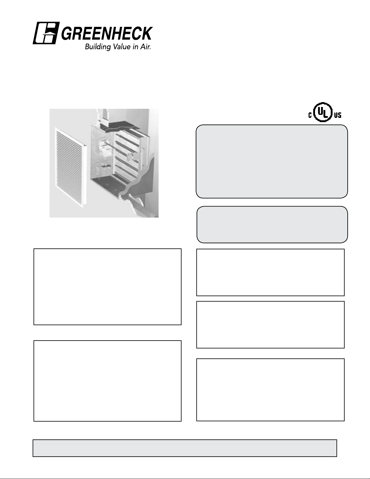
CFSD-XXX SERIES
Corridor Ceiling Dampers
(with factory installed actuator and sleeve)
CFSD models meet the requirements for corridor ceiling
dampers, smoke dampers and combination fire/smoke
dampers established by:
National Fire Protection Association
NFPA Standards 80, 90A, 92A, 92B, 101, & 105
IBC International Building Codes
New York City (MEA listing #260-91-M)
California State Fire Marshal (Listing #3225-0981:106)
and (Listing #3230-0981:105)
“UL CLASSIFIED (see complete marking on product)”
“UL CLASSIFIED to Canadian safety standards (see
complete marking on product)”
UL Standard 555 & 555S (Classification #R13317)
Receiving and Handling
Upon receiving dampers, check for both obvious and
hidden damage. If damage is found, record all necessary
information on the bill of lading and file a claim with
the final carrier. Check to be sure that all parts of the
shipment, including accessories, are accounted for.
Dampers must be kept dry and clean. Indoor storage
and protection from dirt, dust and the weather is highly
recommended. Do not store at temperatures in excess of
100°F (38°C).
Safety Warning
Improper installation, adjustment, alteration, service
or maintenance can cause property damage, injury or
death. Read the installation, operating, and maintenance
instructions thoroughly before installing or servicing this
equipment.
All wiring shall be done in accordance with the National
Electrical Code ANSI/NFPA-70 latest edition, any local
codes that may apply, and wiring diagrams developed
in compliance with the job or project design and
specifications.
Warranty
Greenheck warrants this equipment to be free from
defects in material and workmanship for a period of one
year from the shipment date. Any units or parts which
prove to be defective during the warranty period will be
repaired or replaced at our option. Greenheck shall not
be liable for damages resulting from misapplication or
misuse of its products. Greenheck will not be responsible
for any installation or removal costs. Greenheck will not
be responsible for any service work or backcharges
without prior written authorization.
Electrical input may be needed for this equipment. This
work should be performed by a qualified electrician.
Verify power before wiring actuator. Greenheck is not
responsible for any damage to, or failure of the unit caused
by incorrect field wiring. To avoid causing death or serious
bodily harm to building occupants, follow all instructions
carefully. Dampers must close completely to preserve the
integrity of the fire smoke separation.
Due to continuing research, Greenheck reserves the right to change specifications without notice.
This manual is the property of the owner, and is required for future maintenance. Please leave it with the owner when the
job is complete.
Electrical Guidelines
Important!
Page 3
2 in. x 4 in. wood
or 2 x 2 1/2 in.
steel studs
Retaining angle
(See Section 3)
Grille (supplied by others)
1 in. x 2 1/2 in. 16 ga.
angles either inside
or outside of sleeve
Opening lined with UL
rated 5/8 in. gypsum
board (wood studs only)
d (wood studs only)
Installation - Failure to follow these instructions will void all warranties.
3
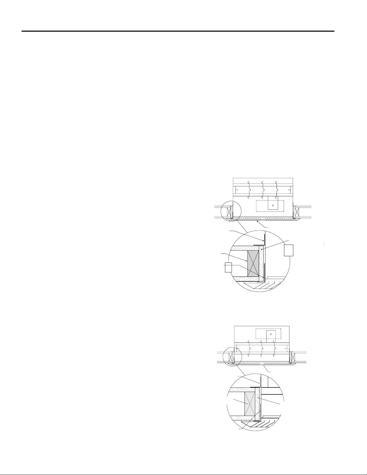
These instructions cover the installation of CFSD-XXX
leakage rated combination fire/smoke dampers with
factory installed actuators and sleeves in corridor
ceiling applications. These instructions meet the
requirements of UL555, UL555S and the Uniform
Building Code.
There are three different configurations available for
this application. Configurations 1 & 2 apply when the
fire rated ceiling is also the finished ceiling and the
damper is installed behind a grille, register or diffuser.
Configuration 3 applies when the fire rated ceiling is
above the finished ceiling and the grille, register or
diffuser is somewhere below the corridor damper.
1. MAXIMUM SIZES
Corridor dampers have a maximum size of
24 in. W x 24 in. H (610mm x 610mm) and a
minimum size of 8 in. W x 6 in. H. (203mm x
152mm).
2. CLEARANCES REQUIRED BETWEEN CORRIDOR
DAMPER SLEEVES AND CEILING OPENINGS
The interior dimension of the prepared ceiling
opening
should be 1/4 in. (6mm) larger than the overall size
of the damper and sleeve assembly.
These are total clearances (ignoring fastener
heads) and do not need to be spaced equally
around the damper.
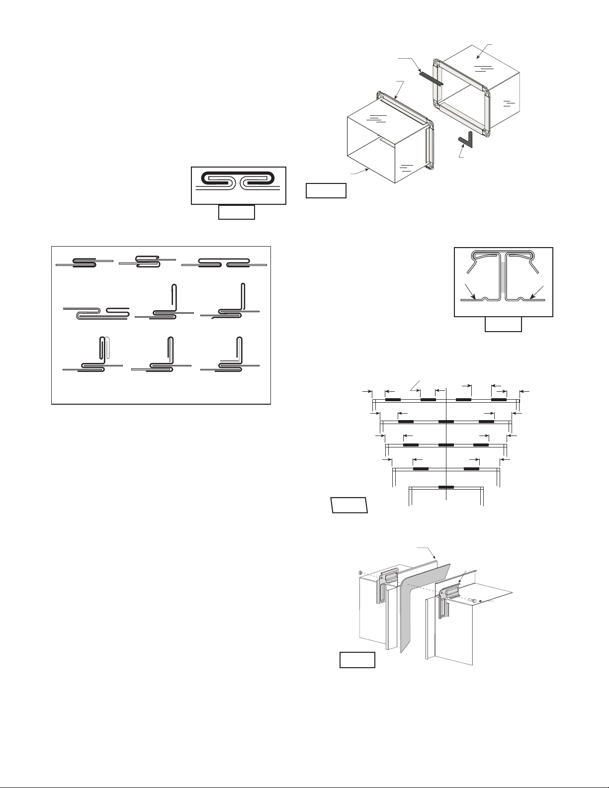
3. SECURING CORRIDOR DAMPER SLEEVES TO FIRE
RATED CEILING OPENINGS
Corridor damper and sleeve assemblies must
be installed in fire rated ceiling openings using
retaining angles on each side of the ceiling as
described below:
Installation of Configurations 1 & 2:
• Retaining angles must be a minimum of 20 ga.
(1mm)steel and have a minimum of 1½ in. x 1¼
in. (38mm x 32mm) legs on the ducted side of the
installation and 1 in. x 2½ in. (25mm x 64mm) legs
on the diffuser, grille or register side.
• The 1 in. x 2½ in. (25mm x 64mm) angle may be
mounted with the 2½ in. (64mm) leg inside or
outside the sleeve
Installation of Configuration 3:
• Retaining angles must be a minimum of 20 ga.
(1mm) steel with 1½ in. x 1¼ in. (38mm x 32mm)
legs.
Retaining angles must be attached to the sleeve
using:
• Tack or spot welds
• No. 10 sheet metal screws
• ¼ in. (6mm) bolts and nuts
• 3/16 in. (5mm) steel pop rivets
The angles must be attached to all 4 sides of the
sleeve with butt joints at each corner. A minimum of
2 attachments are required on each side, top and
bottom. The angles may (but need not) be attached
to each other at the corners.
• Retaining angles must cover the clearance space
between the sleeve and the ceiling opening.
Retaining angles
(See Section 3)
2 in. x 4 in. wood
or 2 in x 2 1/2 in.
steel studs
1 in. x 2 1/2 in. 16 ga.
angles either inside or
outside of sleeve
(Actuator in airstream only)
Allows access to the actuator through the grille or diffuser.
Grille (supplied by others)
Configuration #1
Opening lined with UL
rated 5/8 in. gypsum
boar
Configuration #2
(Actuator in airstream or out of airstream)
Page 4
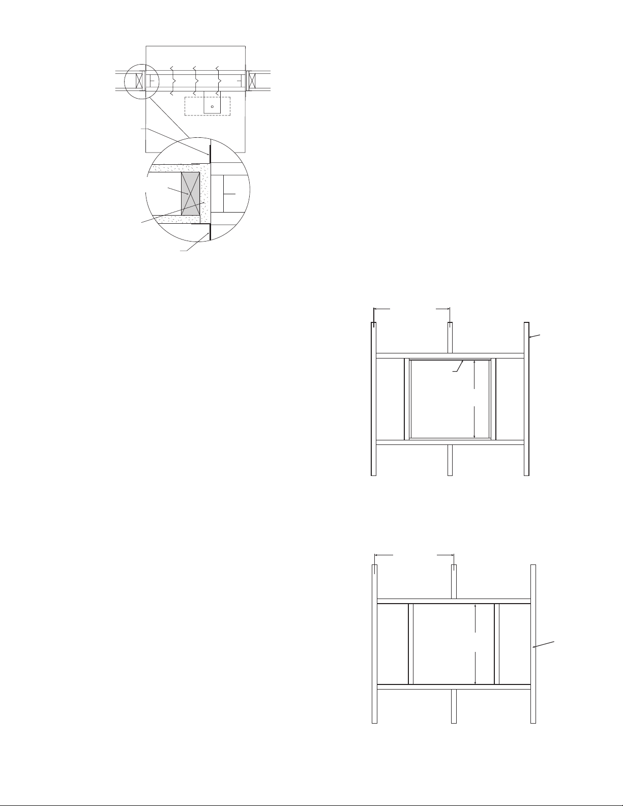
Retaining angle
Steel
studs
Steel Stud Assembly
Wood Stud Assembly
24 in.
max.
24 in. o.c. max.
4
(See Section 3)
2 in. x 4 in. wood
or 2 x 2 1/2 in.
steel studs
Opening lined with UL
rated 5/8 in. gypsum
board (wood studs only)
Retaining angle
(See Section 3)
Configuration #3
(Actuator in airstream or out of airstream)
Actuator can be installed either above or below ceiling
construction
6. PREPARATION OF OPENINGS IN WOOD AND
METAL STUD CORRIDOR CEILINGS
• Corridor dampers are rated in ceiling
constructions with a fire resistance rating of one
hour.
• Frame openings as shown below. Maximum size
of opening is 24 in. x 24 in. (610mm x 610mm).
See Fig. 1 & 2.
• Corridor ceiling must be covered with a minimum
of one sheet of 5/8 in. (16mm) UL rated gypsum
board on both sides.
• All construction and fasteners must meet the
requirements of the appropriate corridor ceiling
design. Gypsum panels should be attached , 12
in. (305mm) O.C. maximum, to all stud and runner
flanges surrounding opening with fasteners as
designated by the appropriate corridor ceiling
design.
24 in. o.c. max.
2 in. x 4 in.
(nominal)
wood studs
4. DUCT TO SLEEVE CONNECTIONS
Dampers are supplied with sleeves and actuators
from the factory and can be installed without the
need for additional field installed sleeves.
Gauge of factory furnished sleeve determines
the type of duct to sleeve connections required.
Any duct connection other than those breakaway
connections described on page three are
considered rigid. Factory furnished round duct
collars on type R and CR are also considered
breakaway.
5. ACTUATOR CONNECTIONS
Electrical and/or pneumatic connections to
damper actuators should be made in accordance
with wiring and piping diagrams developed in
compliance with the job or project design and
specifications.
Opening lined
with UL rated
5/8 in. gypsum
board
24 in. o.c. max.
24 in.
max.
24 in.
max.
Fig. 1
Steel
studs
Steel Stud Assembly
Fig. 2
Page 5
6
9
7 7
55
55
6
Std. Clip
Length
C
L
Duct
60 Duct
4 Reqd.
48 Duct
3 Reqd.
36 Duct
3 Reqd.
24 Duct
2 Reqd.
18 Duct &
Smaller
1 Reqd.
Clip Spacing
6
55
55
Duct End
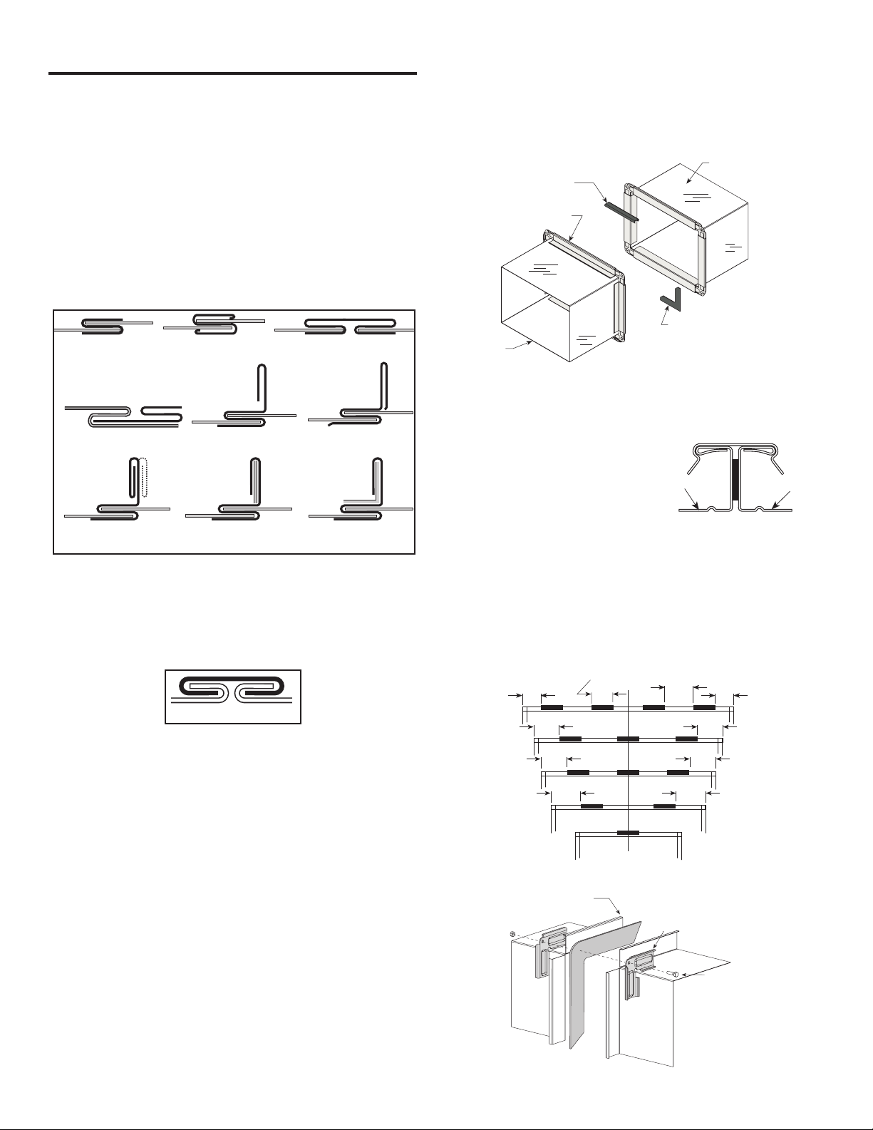
BREAKAWAY CONNECTIONS
Drive Slip Joint
5
Traditional Breakaway Style Transverse
Joints
Transverse joints illustrated at right have always
been approved as breakaway connections. SMACNA
testing has also approved the following variations as
breakaway connections.
• The breakaway connections shown below (Fig. 3)
can be applied with maximum of (2) #10 sheet metal
screws on each side and on the bottom located in
the center of the slip pocket and penetrating both
sides of the slip pocket.
Plain “S” Slip Hemmed “S” Slip Double “S” Slip
Manufactured Flanged System Breakaway
Connections
Flanged connection systems manufactured by
Ductmate, DuroDyne, Ward, and Nexus are approved
as breakaway connections when installed as illustrated.
Fire Damper Sleeve
6 in. long 1/16 in. max.
thickness plastic cleats;
12 in. c-c (min. 1 per side)
Flanged system angles
(Attach per
manufacturer's
instructions)
3/8 in. bolts in
corners are optional
Neoprene or Butyl gasket
between all angles
Duct
Fig. 5
Proprietary Flange System Breakaway
Connections
Inside Slip Joint Standing “S” Standing “S” (Alt.)
Standing “S” (Alt.) Standing “S” Standing “S”
(Bar Reinforced) (Angle Reinfor ced)
Fig. 3
• Transverse joints illustrated can be applied as top
and bottom joints with Drive Slip - side joints in
duct heights up to 20 inches (508mm). See Fig. 4.
Fig. 4
Round and Oval Duct Breakaway
Connections
Round or flat oval ducts connected to Type R, CR or
CO damper collars may use no. 10 sheet metal screws
as follows:
• Ducts to 22 in. (559mm) wide (or dia.) and smaller
may use 3 screws.
• Ducts larger than 22 in. (559mm) wide (or dia.) may
use 5 screws.
NOTE: All breakaway connections described may have
duct sealant applied, PA2084T Duct Sealant Adhesive
manufactured by Precision, DP1010 water base duct
sealant manufactured by Design Polymetrics, Grey
Pookie, Ductmate PROseal® or CL Ward S Seal in
accordance with SMACNA recommendations.
(TDC by Lockformer, TDF by Engle)
TDC and TDF systems (see Fig.
6) are approved as breakaway
connections when installed as
Sleeve
described in the TDC or TDF
addendum to the SMACNA Duct
Construction Standards except
Typical TDC/TDF
joint
Fig. 6
the corners may not be bolted.
Standard 6 in. (152mm) metal clip
may be used with spacing as shown in diagram (see
Fig. 7). 3/8 in. (9.5mm) metal bolts and nuts may be
used to fasten together corner pieces together (see
Fig. 8).
60 Duct
4 Reqd.
48 Duct
3 Reqd.
36 Duct
3 Reqd.
24 Duct
2 Reqd.
Clip Spacing
6
7 7
18 Duct &
Smaller
1 Reqd.
Flange
Std. Clip
Length
6
Duct
9
C
L
Corner Piece
6
3/8 in. bolt
(optional)
Fig. 7
Fig. 8
Duct
Page 6
Damper Maintenance
6
Dampers do not typically require maintenance as long as they are kept dry and clean. If cleaning is necessary,
use mild detergents or solvents. If lubrication is desired for components such as axle bearings, jackshaft
bearings and jamb seals, do not use oil-based lubricants or any other lubricants that attract contaminants such
as dust.
Dampers and their actuator(s) must be maintained, cycled, and tested a minimum in accordance with:
• The latest editions of NFPA 80, 90A, 92A, 92B, 101, 105, UL864, AMCA 503-03 and local codes.
• Actuator manufacturer recommendations.
Damper Troubleshooting
The following is a possible cause and correction list for common concerns with the dampers.
Symptom Possible Cause Corrective Action
Damper does not
fully open and/or
close
RRL or TOR sensor
tripped
Damper does not
operate
Frame is 'racked' causing blades
to bind on jamb seals
Actuator linkage loose Close damper, disconnect power, adjust and
Defective motor Replace
Screws in damper linkage Damper installed too far into wall. Move out
Contaminants on damper Clean with a non-oil based solvent (see
Heat Push reset button located on backside of
No power supplied to the actuator Add power supply
Adjust frame such that it is square and plumb
tighten linkage
to line as designated on damper label
Damper Maintenance)
RRL or TOR
Our Commitment
As a result of our commitment to continuous improvement, Greenheck reserves the right to change specifications without
notice.
Specific Greenheck product warranties are located on greenheck.com within the product area tabs and in the Library
under Warranties.
®
Phone: (715) 359-6171 • Fax: (715) 355-2399 • E-mail: gfcinfo@greenheck.com • Website: www.greenheck.com
461335• CFSD Series Rev. 11, May 2014 Copyright 2014 © Greenheck Fan Corporation
Page 7
Document Number 461336
7
Return to Table of Contents
®
FSD-XXX, DFD-XXX, DFDTF-XXX
CFSD-XXX, SEDFD-XXX, SEFSD-XXX,
IMO-XXX, AND SSFSD-XXX SERIES
1 1⁄2 and 3 Hour
Fire & Combination Fire Smoke Dampers
(with factory installed sleeve and actuator)
Vertical and Horizontal Mount
Installation, Operation and Maintenance Instructions
FSD-XXX, SEFSD-XXX, SSFSD-XXX, DFD-XXX, SEDFDXXX, and CFSD-XXX Series Dampers are intended for
installation in accordance with combination fire smoke
damper requirements established by:
National Fire Protection Association
NFPA Standards 80, 90A, 92A, 92B, 101, & 105
IBC International Building Codes
New York City (MEA listing #260-91-M)
Typical Actuator
RRL Control Device
Standard
California State Fire Marshal
(Listing #3225-0981:103) & (Listing #3230-0981:104) - FSD
& SSFSD models; (Listing #3225-0981:103) - DFD models;
(Listing #3230-0981:105) & (Listing 3225-0981:106) - CFSD
models
Installation Supplements
Refer to the appropriate Greenheck installation supplements
for special requirements:
• Concrete Floor with Steel Deck
• Drive Slip Breakaway Connection
• Field Installed Sleeve
• Fire Resistant Ventilated Duct Assembly
• Firestop Material
• Greenheck Test Switch
• Grille Installation
• Metal Stud in Shaftwall
• No Flow Smoke Detector
• Open or Close Indicator
• Quick Connect Breakaway Connections
• Resettable Link
• Sealant Supplement
• Single Side Retaining Angle
• Single 3-Sided Retaining Angle
• Sleeve Extension
• Smoke Detector
• Tunnel Corridor
Safety Warning:
Improper installation, adjustment, alteration, service
or maintenance can cause property damage, injury or
death. Read the installation, operating, and maintenance
instructions thoroughly before installing or servicing this
equipment.
“UL CLASSIFIED (see complete marking on product)”
“UL CLASSIFIED to Canadian safety standards
(see complete marking on product)”
UL Standard 555 & 555S (Classification #R13317)
Receiving and Handling
Upon receiving dampers, check for both obvious and
hidden damage. If damage is found, record all necessary
information on the bill of lading and file a claim with
the final carrier. Check to be sure that all parts of the
shipment, including accessories, are accounted for.
Dampers must be kept dry and clean. Indoor storage
and protection from dirt, dust and the weather is highly
recommended. Do not store at temperatures in excess of
100°F (38°C).
Warranty
Greenheck warrants this equipment to be free from
defects in material and workmanship for a period of one
year from the purchase date. Any units or parts which
prove to be defective during the warranty period will be
repaired or replaced at our option. Greenheck shall not
be liable for damages resulting from misapplication or
misuse of its products. Greenheck will not be responsible
for any installation or removal costs. Greenheck will not
be responsible for any service work or backcharges
without prior written authorization.
Due to continuing research, Greenheck reserves the right to change specifications without notice.
This manual is the property of the owner, and is required for future maintenance. Please leave it with the owner when the
job is complete.
Page 8

Table of Contents
8
Pre-Installation Guidelines ................................................................................................................................ 8
Electrical Guidelines .......................................................................................................................................... 8
Installation ......................................................................................................................................................9-13
•
Clearances Required Between Fire Damper Sleeves and Wall/Floor Openings ............................ 9
•
Sleeve Length and Wall Thickness .................................. .............................................................9-10
•
Duct to Sleeve Connections .............................................................................................................10
•
Securing the Damper/Sleeve Assembly to Wall and Floor Openings ........................ ...................10
•
Actuator Connections ..................................... .................................................................................11
•
Installing Multiple Damper Section Assemblies ..............................................................................11
•
Connection and Operation of Temperature Control Devices .........................................................12
•
Recommended Preparation of Openings in Wood and Metal Stud Walls ........................... .........13
•
Breakaway Connections ........................................ .........................................................................14
Maintenance .....................................................................................................................................................15
Troubleshooting ................................................................................................................................................15
Pre-Installation Guidelines
The basic intent of a proper installation is to secure the
fire or fire smoke damper in, not to, the opening in such a
manner as to prevent distortion and disruption of damper
operation. This is accomplished by allowing the fire or fire
smoke damper in rated separation openings to expand
and for the connecting duct to separate in the event of the
collapse of the hanging system. The following items will
aid in completing the damper installation in a timely and
effective manner.
1) Check the schedules for proper damper locations
within the building. Visually inspect the damper for
damage and verify that the Reusable Resettable Link
(RRL) is in place or has not activated. Never install a
fire damper without the proper UL approved RRL in
place. (RRL is standard control option. These electric
links have a button for resetting.) If damper is furnished
with fusible link, visually inspect the link to verify its not
missing or broken. Replace link as necessary.
2) Lift or handle damper using sleeve or frame. Do not lift
damper using blades or actuators.
3) Damper has label on outside of sleeve indicating a
‘No Screw’ area. Do not install screws into this area as
screws may interfere with unexposed blade linkage and
prevent damper blades from opening and/or closing.
4) Damper has label indicating position of damper
and sleeve assembly in the wall. Install accordingly
to comply with manufacturer’s appropriate UL
Classification file number.
5) Damper must be installed into duct or opening square
and free of twist or other misalignment. Damper must
not be squeezed or stretched into duct or opening. Out
of square, racked, twisted or misaligned installations
can cause excessive leakage and/or torque
requirements to exceed damper/actuator design.
6) Damper and actuator must be kept clean and
protected from dirt, dust and other foreign materials
prior to and after installation. Examples of such foreign
materials include but are not limited to:
a) Mortar dust
b) Drywall dust
c) Firesafing materials
d) Wall texture
e) Paint overspray
7) Damper should be sufficiently covered as to prevent
overspray if wall texturing or spray painting will be
performed within 5 feet of the damper. Excessive dirt
or foreign material deposits on damper can cause
excessive leakage and/or torque requirements to
exceed damper/actuator design.
8) Caulking is not necessary, nor is it allowed, between
the damper sleeve and the wall or floor opening
(annular space). However, caulking may be applied to
the retaining angles.
9) ACCESS: Suitable access (such that RRL’s and
actuators can be maintained, etc.) must be provided
for damper inspection and servicing. Where it is not
possible to achieve sufficient size access, it will be
necessary to install a removable section of duct. (Refer
to NFPA 90A).
10) The Code Authority Having Jurisdiction (AHJ) must
evaluate and provide approval of final installation
where variations to these instructions are necessary.
Electrical Guidelines
Electrical Guidelines
All wiring shall be done in accordance with the National
Electrical Code ANSI/NFPA-70 latest edition, any local
codes that may apply, and wiring diagrams developed
in compliance with the job or project design and
specifications.
Electrical input may be needed for this equipment. This
work should be performed by a qualified electrician.
Verify power before wiring actuator. Greenheck is not
responsible for any damage to, or failure of the unit
caused by incorrect field wiring. To avoid causing death
or serious bodily harm to building occupants, follow all
instructions carefully. Dampers must close completely to
preserve the integrity of the fire smoke separation.
Important!
Page 9
Installation - Failure to follow these instructions will void all warranties.
9
1
These instructions apply to 1
masonry, block or stud walls and 2) concrete floors or ceilings. Specific requirements in these instructions are mandatory. Dampers
must be installed in accordance with these instructions to meet the requirements of UL 555 and UL 555S. The installation of the
damper and all duct connections to the damper sleeve shall conform to the latest editions of NFPA 90A, Standard for the
Installation of Air Conditioning and Ventilating Systems, and the SMACNA Fire, Smoke and Radiation Damper Installation
Guide, and UL Classifications R13317.
Note: Combination fire smoke dampers are manufactured and labelled for either vertical or horizontal installation. The
dampers must be installed in accordance with labelling.
1. CLEARANCES REQUIRED BETWEEN FIRE DAMPER
SLEEVES AND WALL/FLOOR OPENINGS
Fire damper and sleeve assemblies expand during periods
of intense heat. Therefore, it is essential that openings in
walls or floors be larger than the fire/smoke damper and
sleeve assembly to allow for this expansion. Minimum
clearances required between the outside of fire damper
sleeve assemblies and wall/floor openings are:
• Galvanized steel fire dampers and sleeves: 1⁄8 in. per
foot (3mm per .3 m) of damper width and
(3mm per .3 m) height with a minimum clearance of
(6mm), maximum of 1 1⁄2 in. (38mm).
Recommended clearances, for width and/or height
dimensions of:
1) 48 in. (1219mm) or less:
/2 and 3 hour rated combination fire smoke dampers mounted (blades must be horizontal) in: 1)
2) More than 48 in. (1219mm) and 96 in. (2438mm) or
less: 1 in. (25mm) clearance
3) More than 96 in. (2438mm): 11⁄2 in. (38mm) clearance
• Stainless steel fire/smoke dampers and stainless steel
3
or galvanized sleeves:
⁄16 in. per foot (5mm per .3 m) of
damper width and height with a minimum clearance of
1/4 in. (6mm), maximum of 2 in. (51mm).
Recommended clearances, for width and/or height
1
⁄8 in. per foot
1
⁄4 in.
dimensions of:
1) 48 in. (1219mm) or less: 3⁄4 in. (19mm) clearance.
These are total clearances (ignoring fastener heads) and
do not need to be equally spaced around the damper.
Refer to Section 4 and Figure 6 for additional installation
1
⁄2 in. (13mm) clearance
considerations.
Fig. 1
Access door required on
jackshaft side of damper.
Refer to the latest edition
of NFPA 90A.
Damper
Sleeve
Dampers may be mounted either vertically or horizontally. Blade axis must always be horizontal.
Example:
A 12 in. x 12 in. (305mm x 305mm) will
require a minimum clearance of 1/4
in. (6mm) width and 1/4 in. (6mm) on
height
A 36 in. x 12 in. (914mm x 305mm)
damper will required a minimum
clearance of 1/2 in. (13mm) on width
and 1/4 in. (13mm) on height.
Optional blade indicator
and/or electric link.
Airflow
Jackshaft
Actuator
‘A’ Dim.
(Distance from
end of sleeve to
face of damper)
16 in. max.
Sleeve Length (L)
Clearance for expansion
(1/4 in. min., 1 1/2 in. max.)
Retaining Angles
(see Section 4)
LIne of Wall
DO NOT INSTALL SCREWS
LINE OF WALL
DO NOT INSTALL SCREWS
BETWEEN THESE LINES
AROUND ENTIRE DAMPER
C
L
6 in. max.
T
w
BETWEEN THESE LINES
AROUND ENTIRE DAMPER
Detail 1
458549
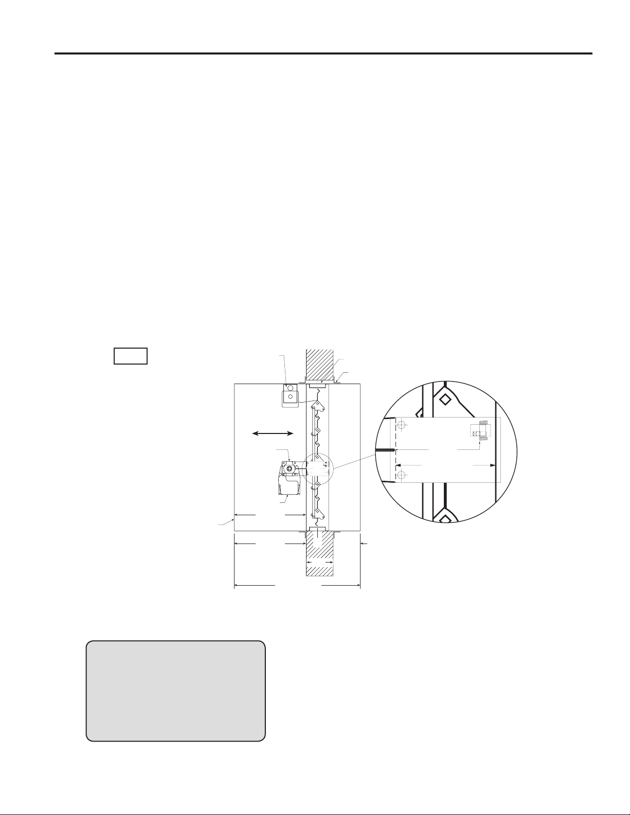
2. SLEEVE LENGTH AND WALL THICKNESS
Insert the sleeved damper assembly into the prepared
opening, to appropriate depth (refer to label on
outside of sleeve for location of damper in wall; see
Dimension A and Detail 1, Fig. 1).
Recommended maximum and minimum insertion depth
can be exceeded if:
1) The operation of the damper is not impeded and
2) The CL of the damper frame remains within the plane
of the wall and
3) Attachments made through the retaining angle do not
penetrate the ‘No Screw’ area designated on the
damper sleeve.
Page 10
Wall or Floor
Sleeve
Duct
Damper
Type B
Wall or Floo
r
IMPORTANT SAFETY DANGER! : To avoid causing
10
death or serious bodily harm to building occupants, do
not penetrate the ‘No Screw’ area designated on the
damper sleeve or the damper may not close properly.
The sleeve may extend a maximum of 16 in. (406mm)
beyond the wall or floor on the actuator side of the
damper and a maximum of 6 in. on the opposite side.
Recommended standard sleeve lengths for various wall
thicknesses are:
)
Sleeve Length
Dimension (L)
16 in.
(406mm)
21 in.
(533mm)
24 in.
(610mm)
Wall Thickness
Dimension (T
4 - 6 in.
(102mm - 152mm)
7 - 10 in.
(178mm - 254mm)
11 - 13 in.
(279mm - 330mm)
W
3. DUCT TO SLEEVE CONNECTIONS
Dampers are supplied with sleeves and actuators from
the factory and can be installed without the need for
additional field installed sleeves.
Gauge of factory furnished sleeve determines the
type of duct to sleeve connections required (see table
below). Any duct connection other than the breakaway
connections described on page 7 are considered rigid.
Factory furnished duct collars, type R and O, are also
considered breakaway (see Fig. 2).
Type of Duct
Sleeve Gauge Duct Dimension
to Sleeve
Connection
Permitted
14 ga. (0.075 in.)
- 10 ga. (0.138
in.)
[2mm - 3.5mm]
16 ga. (0.060 in.)
[1.5mm]
16 ga. (0.060 in.)
[1.5mm]
18 ga. (0.048 in.)
[1.2mm]
20 ga. (0.036 in.)
22 ga. (.030 in.)
26 ga. (0.018 in.)
See page 7 for additional information on breakaway sleeve connections.
Sleeve thickness must not be less than the gauge of the connecting duct.
UL Standard 555 requires all ducts to terminate at fire damper sleeves.
[0.9mm]
[0.76mm]
24 ga. (0.024)
[0.6mm]
[0.46mm]
All duct sizes
36 in. (914mm) max. width
24 in. (610mm) max.
24 in. (610mm) diameter
85 in. (2159mm) wide and
55 in. - 84 in. wide
(1397mm - 2134mm)
31 in. - 54 in. wide
(787mm - 1372mm)
13 in. - 30 in. wide
(330mm - 762mm)
12 in. wide and under
height
All duct sizes
over
(305mm)
Rigid or
Breakaway
Rigid or
Breakaway
Breakaway only
Type R and O
factory furnished
duct collars qualify
as breakaway
connections.
Fig. 2
Duct
Type C, R
Sleeve
Damper
4. SECURING THE DAMPER/SLEEVE ASSEMBLY TO
WALL AND FLOOR OPENINGS (for single side retaining
angle instructions, see supplements)
Damper/sleeve assemblies must be installed in wall and
floor openings using retaining angles on at least one side
of the wall or floor as described below:
• Retaining angles for 1½ hour rated dampers with a
width and height 48 in. (1219mm) or less must be a
minimum of 20 ga. (1mm). Retaining angles for all 3 hour
rated dampers and all dampers with a width or height
greater than 48 in. (1219mm) must be a minimum of 16
gauge (1.5mm). The leg of the retaining angle on the
damper sleeve shall be a minimum of 1¼ in. (32mm).
The leg of the retaining angle on the wall/floor shall be
long enough to cover the annular space and overlap the
wall/floor by a minimum of 1 in. (25mm).
• Retaining angles must be attached to the damper using
one or more of the following methods of attachment
(refer to label on outside of sleeve for ‘No Screw’ area):
• Tack or spot welds
• #10 (3/4 in. [19mm] max.) sheet metal screws
1
•
/4 in. (6mm) bolts and nuts
3
•
/16 in. (5mm) steel pop rivets
A minimum of two connections per side, top, and bottom,
12 in. (305mm) O.C. maximum for openings of
48 in. W x 36 in. H (1219mm x 914mm) and less, and 6 in.
(152mm) O.C. for openings 80 in. W x 50 in. H
(2032mm x 1270mm), 50 in. W x 72 in. H (1270mm x
1829mm), and 40 in. W x 72 in. H (1016mm x 1829mm)
or less. The angles must be attached to all 4 sides of the
sleeve. Ensure that attachment device does not interfere
with the operation of the damper and the free movement
of the damper blades. The angles need not be attached
to each other at the corners. Do not secure the retaining
angle to the fire separation (see Fig. 3).
• Retaining angles should not be fastened to the wall/
floor material. The angles should only sandwich the
wall/floor and allow for damper expansion during
periods of intense heat.
Page 11
Wall or
11
Floor
Min. 1 in.
Damper
Overlap*
Retaining
Angle
Sleeve
Duct
Fig. 3
Retaining
Angle
2 in. Max.
6 in. Max.
6 in. Max.
2 in. Max.
*only applicable for damper sizes above 36 in. x 36 in.
Both vertical and horizontal damper installations are typified by these
drawings.
5. ACTUATOR CONNECTIONS
Electrical and/or pneumatic connections to damper
actuators should be made in accordance with wiring and
piping diagrams developed in compliance with applicable
codes, ordinances and regulations (see Electrical
Guidelines).
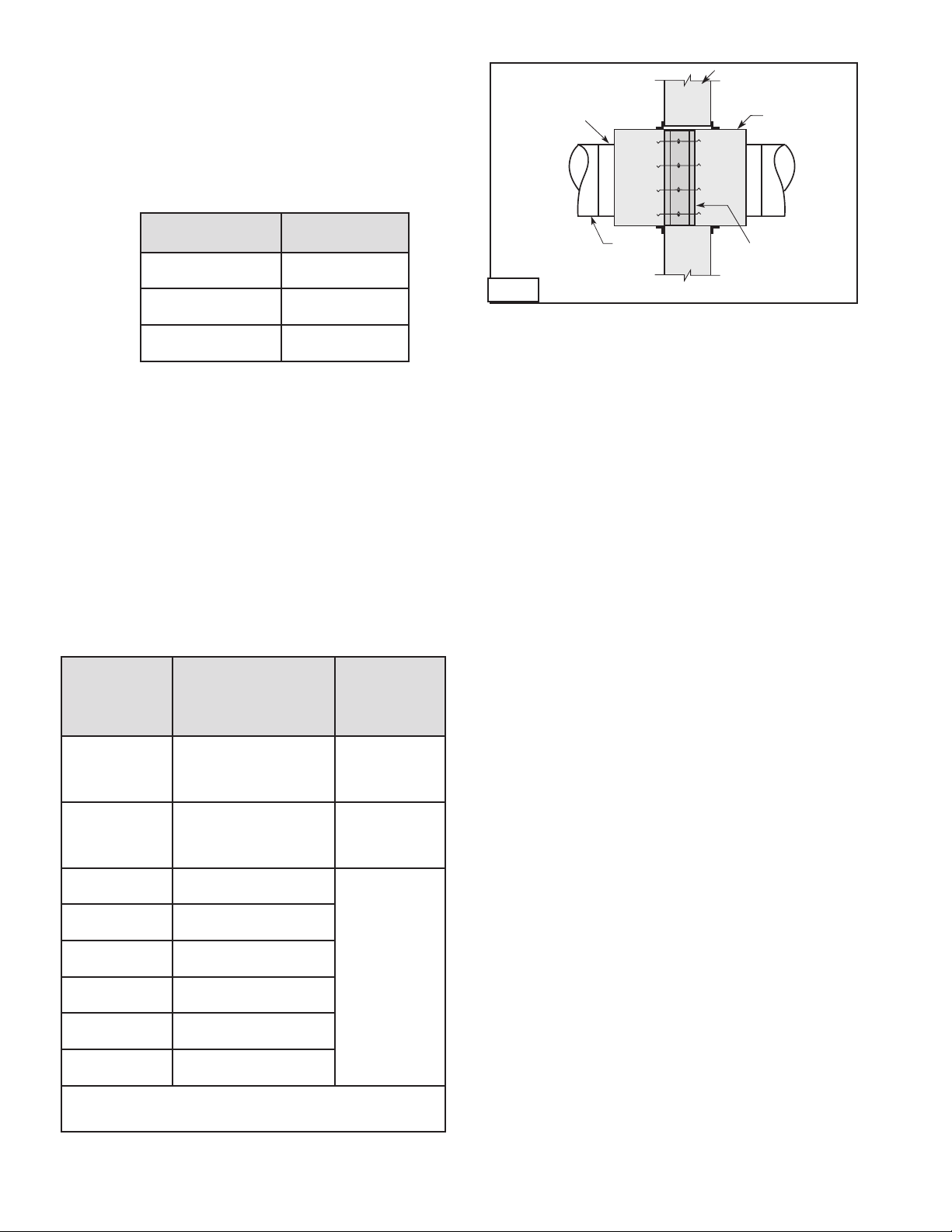
6. INSTALLING MULTIPLE DAMPER SECTION
ASSEMBLIES
A damper assembly is not restricted to a maximum
number of sections, but must not exceed the section
sizes and overall sizes shown (see chart).
Two section high dampers require reinforcement using a
14 gauge (2mm), 5 in. (127mm) wide mullion as shown in
Fig. 4 below, or two individually sleeved units stacked
vertically, shown below in Fig. 5. When using two
individually sleeved units, the sleeve acts as the mullion,
therefore no mullion is required.
The damper sections must be attached together with
#10 (3/4 in. max. [19mm]) sheet metal screws, 1/4 in. (6mm)
diameter nuts and bolts, tack or spot welds, or 3/16 in.
(48mm) diameter steel pop rivets. Attachments must be
spaced a maximum of 6 in. (152mm) on centers and a
maximum of 2 in. (51mm) from corners. Attachments must
be made on front face and back face (air entering and air
exiting side) of damper sections.
Note: Dampers ordered for individual installation may
not be installed together. The full assembly size must be
specified at the time the dampers are ordered.
14 ga.
5 in. wide
support
mullion
Horizontal Mount
Maximum Single
Damper Model
Section Size in a
Multiple Section
Assembly
CFSD-211, 212 24 x 24 NA
DFD-210 32 x 50 128 x 96
DFD-230 32 x 48 72 x 48
DFDAF-310 32 x 50 96 x 50
DFDTF-210
FSD-211, 212, 213 36 x 48 or 32 x 50 144 x 96
FSD-211M, 212M 36 x 36 144 x 72
FSD-231 36 x 36 or 32 x 48 72 x 48
FSD-311, 311M, 312,
312M
IMO-310 32 x 50 NA
IMO-311 32 x 50 NA
SEDFD-210,
SEFSD-211
SSFSD-211 24 x 30 48 x 30
FSD-231M 32 x 36 72 x 48
32 x 36 96 x 72
32 x 48 64 x 48 or 32 x 96
32 x 50 96 x 50
24 x 30 48 x 30
Maximum Over-
all Size for
Multi-Section
Dampers
Vertical Mount
Maximum Single
Damper Model
Section Size in a
Multiple Section
Assembly
DFD-210 32 x 50 128 x 100
DFD-230 32 x 50 72 x 48
DFDAF-310 32 x 50 128 x 100
DFDTF-210
FSD-211, 212, 213 36 x 48 or 32 x 50 128 x 100
FSD-211M, 212M 36 x 36 128 x 72
FSD-231 36 x 36 or 32 x 48 72 x 48
FSD-311, 311M,
312, 312M
IMO-311
SEDFD-210,
SSDFD-210
SEFSD-211
SSFSD-211
FSD-331; DFDAF-330 30 x 48 120 x 96
FSD-231M 32 x 36 72 x 48
32 x 36 96 x 72
32 x 50 64 x 50
32 x 50 128 x 100
32 x 50 NA
32 x 50 NA
24 x 30 or 22 x 36 48 x 30
24 x 30 or 22 x 36 88 x 72
Maximum
Overall Size for
Multi-section
Dampers
Fig. 4
Single Sleeve Around Outside with
Support Mullion
Fig. 5
Two Individually Sleeved Units
with No Mullions
NOTE: FSD model dampers fitted with a fusible link closure
device are limited to single section sizes. Dampers with a
fusible link and spring assembly closure device may not be
used for multiple section applications.
Page 12
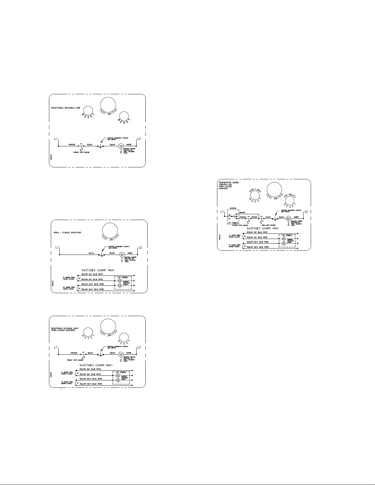
7. CONNECTION AND OPERATION OF TEMPERATURE
12
RESPONSE DEVICES (RRL STANDARD, OCI OPTION,
AND TOR OPTION)
RRL - Dampers will be supplied with a thermostat-type
temperature response device, as a standard. The device
is a RRL (resettable link device), which only incorporates
one thermostat and therefore the damper remains
closed as soon as its sensor temperature is reached.
The RRL does not contain blade indication switches.
Refer to Fig. 6 for wiring of the RRL thermostat.
Fig. 6 RRL Wiring
OCI - The OCI (open or closed indicator) option
contains a single pole, double throw switch used
to indicate the damper blade position. The switch
provides a positive open or closed signal when used in
conjunction with remote indicator lights. Refer to Fig. 7
& 8 for wiring of the OCI option.
TOR - The TOR (temperature override device) option
incorporates two thermostats with fixed settings (usually
165°F [74°C] and 350°F [177°C]). The primary sensor
(the sensor with the lower temperature setting) can be
bypassed by an external electrical signal allowing the
damper to reopen until the temperature reaches the
setting of the secondary sensor (the sensor with the
higher temperature setting).
See Fig. 8.
When the temperature of the secondary sensor is
exceeded the damper closes and remains closed
thereafter.
The TOR assembly also contains a single pole, double
throw switch used to indicate damper blade position. The
switch provides a positive open or closed signal when
used in conjunction with remote indicator lights. See
Fig. 8 for wiring of the TOR thermostats and indicator
switches.
If either the TOR or the RRL is ordered with a pneumatic
actuator, an EP switch is required with an appropriate
electric power circuit to allow the electric thermostat to
control the pneumatic actuator.
Fig. 7 OCI Wiring
Fig. 8 RRL/OCI Wiring
Fig. 9 TOR Wiring
PRV - The PRV (pneumatic relief valve) option is heat
responsive device used with pneumatic actuators. This
can be used in place of EP switch where a RRL is used.
The PRV activates when temperature in excess of the
temperature of the fusible link are detected. When the
fusible link melts, air from the actuator is exhausted to
close the dampers. Pneumatic actuators are to be piped
per local code.
RATINGS (Fig. 6, 7, 8 & 9)
Integral Switch Type: Single Pole, double throw
Electrical Capacity: 10 Amps, 1/3 hp, 120 or 240 Vac
1/2 Amp, 125 Vdc;
1/4 Amp 250 Vdc
5 Amps, 120 Vac “L” ( lamp load)
1.0 Amps, 24 Vac
1.5 Amps, 24 Vdc
Temperature Limit: 165° F (standard primary sensor)
212° F (optional primary sensor)
250° F (secondary sensor )*
350º F (secondary sensor)*
* based on actuator temperature rating
Page 13
Metal Stud Construction
In metal stud construction,
exposed steel surfaces need
not be covered with gypsum
wallboard.
Gypsum Wallboar d
Stud or Runner
Retaining
Angle
1 in. Min.
Damper
Sleeve
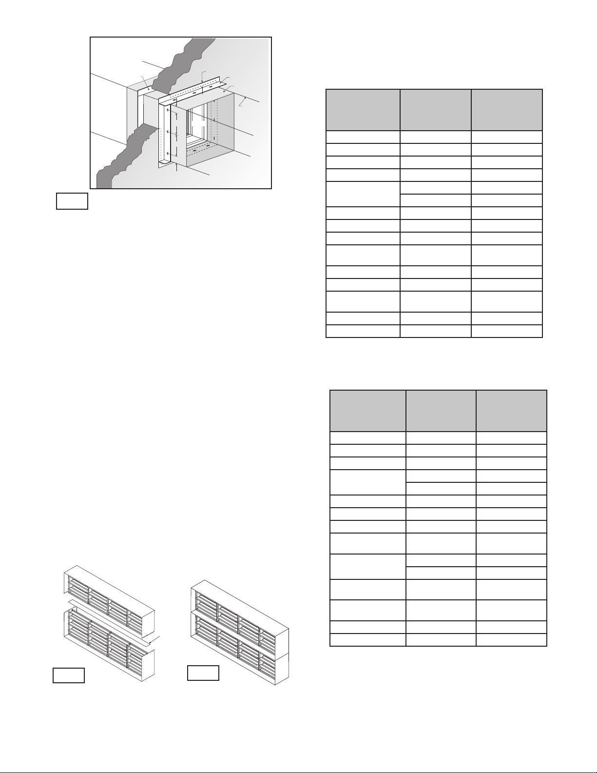
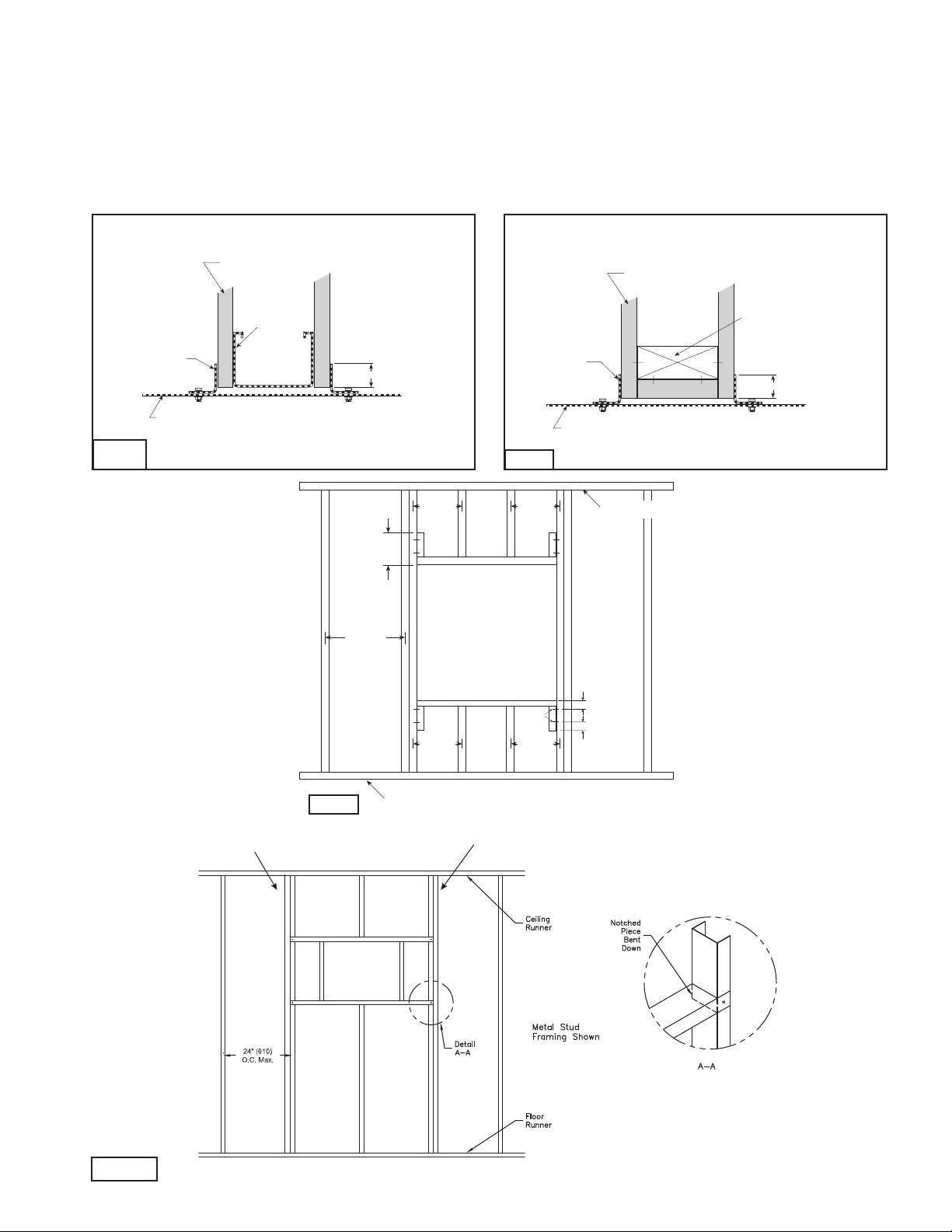
8. Recommended Preparation of Openings in Wood and Metal Stud Walls
Metal Stud Construction
13
• Frame wall openings as shown below(see Fig. 12 & 12A).
• Gypsum wall board must be fastened 12 in. (305mm) on center to all stud and runner flanges surrounding opening (see
Fig. 12 & 12A).
• Prepare opening between studs and sleeve assembly as shown below (see Fig. 10 & 11).
• All construction and fasteners must meet the requirements of the appropriate wall design (See UL Fire Resistance
Directory) and/or local codes.
Wooden Stud Construction
Gypsum Wallboar d
Gypsum Wallboard
Retaining
Angle
Damper
Sleeve
Fig. 10
Stud or Runner
In metal stud construction,
exposed steel surfaces need
not be covered with gypsum
wallboard.
Fig. 12
Second set of studs are not required on openings
36 in. x 36 in. (914mm x 914mm) or smaller.
1 in. Min.
24 in. o.c.
Maximum
12 in.
Floor Runner
24 in. o.c.
Maximum
(metal studs)
16 in. o.c.
Maximum
(wood studs)
Fig. 11
24 in. o.c.
Maximum
(metal studs)
2 Panhead
Screws
16 in. o.c.
Maximum
(wood studs)
Retaining
Angle
Damper
Sleeve
In wood stud construction,
gypsum wallboard must cover
all wood stud surfaces.
Ceiling Runner
2 in. (51mm)
2 in. (51mm)
Stud or Runner
1 in. Min.
Fig. 12A
Page 14
6 in.
Std. Clip
Length
C
L
Duct
60 in. Duct
4 Req’d.
48 in. Duct
3 Req’d.
36 in. Duct
3 Req’d.
24 in. Duct
2 Req’d.
18 in. Duct &
Smaller
1 Req’d.
Clip Spacing
6 in. 6 in.
9 in.
7 in.7 in.
5 in. 5 in.
5 in.5 in.
Duct End
9. DUCT-SLEEVE CONNECTIONS
Drive Slip Joint
6 in.
Std. Clip
Length
60 in. Duct
4 Req’d.
48 in. Duct
3 Req’d.
36 in. Duct
3 Req’d.
24 in. Duct
2 Req’d.
Clip Spacing
6 in. 6 in.
9 in.
7 in.7 in.
5 in. 5 in.
5 in.5 in.
14
Traditional Breakaway Style Transverse Joints
Transverse joints illustrated at right have always been
approved as breakaway connections. SMACNA testing
has also approved the following variations as breakaway
connections.
• The breakaway connections shown (Fig. 14) can be
applied with maximum of two #10 (19mm) sheet metal
screws on each side and on the bottom located in the
center of the slip pocket and penetrating both sides of
the slip pocket.
• Transverse joints illustrated
can be applied as top and
bottom joints with Drive Slip side joints in duct heights up
to 20 inches (508mm)
Fig. 13
See Fig. 13.
Plain “S” Slip Hemmed “S” Slip Double “S” Slip
Inside Slip Joint Standing “S” Standing “S” (Alt.)
Fire Damper Sleeve
6 in. long 1/16 in. max.
thickness plastic cleats;
12 in. c-c (min. 1 per side)
Flanged system angles
(Attach per
manufacturer's
instructions)
3/8 in. bolts in
corners are optional
Neoprene or Butyl gasket
between all angles
Duct
Fig. 15
Proprietary Flange System Breakaway Connections
(TDC by Lockformer, TDF by Engle)
TDC and TDF systems are approved as breakaway
connections when installed as described in the TDC or
TDF addendum to the SMACNA
Duct Construction. Standard 6 in.
(152mm) metal clip may be used
with spacing as shown in diagram
(see Fig. 15 & 16). 3/8 in. (9.5mm)
metal bolts and nuts may be used
to fasten together corner pieces.
(see Fig. 17)
Sleeve
Typical TDC/TDF joint
Fig. 16
Duct
Standing “S” (Alt.) Standing “S” Standing “S”
(Bar Reinforced)
(Angle Reinforced)
Fig. 14
Round and Oval Duct Breakaway Connections
Round or flat oval ducts connected to Type R or O damper
collars shall be attached with #10 (19mm) sheet metal
screws as follows:
• Ducts to 22 in. (558mm) wide (or dia.) and smaller
shall have three screws.
• Ducts larger than 22 in. (558mm) wide (or dia.) up to
and including 36 in. (914mm) wide (or dia.) shall have
five screws.
NOTE: All breakaway connections described may have duct
sealant applied, PA2084T duct sealant adhesive
manufactured by Precision, DP1010 water base duct
sealant manufactured by Design Polymetrics, Grey Pookie,
Ductmate PROseal
®
, or CL Ward S Seal in accordance with
SMACNA recommendations.
Manufactured Flanged System Breakaway
Connections
Flanged connection systems manufactured by Ductmate,
Durodyne, Ward, and Nexus are approved as breakaway
connections when installed as illustrated (Fig. 15).
Fig. 17
Fig. 18
Flange
Corner Piece
3/8 in. bolt
(optional)
Page 15
Damper Maintenance
15
Dampers do not typically require maintenance as long as they are kept dry and clean. If cleaning is necessary, use mild
detergents or solvents. If lubrication is desired for components such as axle bearings, jackshaft bearings and jamb seals, do
not use oil-based lubricants or any other lubricants that attract contaminants such as dust.
Dampers and their actuator(s) must be maintained, cycled, and tested a minimum in accordance with:
• The latest editions of NFPA 80, 90A, 92A, 92B, 101, 105, UL864, AMCA 503-03 and local codes.
• Actuator manufacturer recommendations.
Damper Troubleshooting
The following is a possible cause and correction list for common concerns with the dampers.
Symptom Possible Cause Corrective Action
Damper does not fully
open and/or close
RRL or TOR sensor
tripped
Damper does not
operate
Frame is 'racked' causing blades to bind
on jamb seals
Actuator linkage loose Close damper, disconnect power, adjust and tighten
Defective motor Replace
Screws in damper linkage Damper installed too far into wall. Move out to line as
Contaminants on damper Clean with a non-oil based solvent (see Damper
Heat Push reset button located on backside of RRL or TOR
No power supplied to the actuator Add power supply
Adjust frame such that it is square and plumb
linkage
designated on damper label
Maintenance)
Our Commitment
As a result of our commitment to continuous improvement, Greenheck reserves the right to
change specifications without notice.
Specific Greenheck product warranties are located on greenheck.com within the product
area tabs and in the Library under Warranties.
®
Phone: (715) 359-6171 • Fax: (715) 355-2399 • E-mail: gfcinfo@greenheck.com • Website: www.greenheck.com
461336• FSD DFD CFSD Series Rev. 22, November 2014 Copyright 2014 © Greenheck Fan Corporation
Page 16
Document Number 461337
16
Return to Table of Contents
®
OFSD-XXX, ODFD-XXX,
OFD-XXX, and OSSFD-XXX Series
1½ Hour Combination Fire Smoke or Curtain Fire Dampers
Out of Wall or Out of Floor
Vertical or Horizontal Mount
Installation, Operation, and Maintenance Instructions
OFSD-XXX, ODFD-XXX, OFD-XXX, and OSSFD-XXX
series dampers are intended for installation in accordance
with combination fire smoke dampers requirements
established by:
NFPA National Fire Protection Association
NFPA Standards 80, 90A, 92A, 92B, 101, & 105
IBC International Building Codes
New York City (MEA listing # 260-91-M)
California State Fire Marshal
Listing #3225-0981:103 & 3230-0981:104
“UL Classified (see complete marking on product)”
“UL Classified to Canadian safety standards (see
complete marking on product)”
UL Standard 555 & 555S (Classification R13317)
Receiving and Handling
Upon receiving dampers, check for both obvious and
hidden damage. If damage is found, record all necessary
information on the bill of lading and file a claim with
the final carrier. Check to be sure that all parts of the
shipment, including accessories, are accounted for.
Dampers must be kept dry and clean. Indoor storage
and protection from dirt, dust and the weather is highly
recommended. Do not store at temperatures in excess
of 100°F (38°C).
Warranty
Greenheck warrants this equipment to be free from
defects in material and workmanship for a period of one
year from the purchase date. Any units or parts which
prove to be defective during the warranty period will
be repaired or replaced at our option. Greenheck shall
not be liable for damages resulting from misapplication
or misuse of its products. Greenheck will not be
responsible for any installation or removal costs.
Greenheck will not be responsible for any service work
or backcharges without prior written authorization.
Electrical Guidelines
All wiring shall be done in accordance with the National
Electrical Code ANSI/NFPA-70 latest edition, any local
codes that may apply, and wiring diagrams developed
in compliance with the job or project design and
specifications.
Safety Warning:
Improper installation, adjustment, alteration, service
or maintenance can cause property damage, injury or
death. Read the installation, operating, and maintenance
instructions thoroughly before installing or servicing this
equipment.
Important!
Electrical input may be needed for this equipment. This
work should be performed by a qualified electrician.
Verify power before wiring actuator. Greenheck is not
responsible for any damage to, or failure of the unit
caused by incorrect field wiring. To avoid causing death
or serious bodily harm to building occupants, follow all
instructions carefully. Dampers must close completely to
preserve the integrity of the fire smoke separation.
Due to continuing research, Greenheck reserves the right to change specifications without notice.
This manual is the property of the owner, and is required for future maintenance. Please leave it with the owner when
the job is complete.
Page 17

Table of Contents
17
Pre-Installation Guidelines ................................................................................................................................17
Installation ....................................................................................................................................................17-27
•
Clearances Requirements .................................................................................................................18
•
Duct to Sleeve Connections ...................................... .......................................................................24
•
Securing the Damper/Sleeve Assembly to Wall and Floor Openings ........................................24-25
•
Actuator Connections ................................... ...................................................................................25
•
Recommended Preparation of Openings in Wood and Metal Stud Walls .................................... 25
•
Breakaway Connections ...................................... .......................................................................26-27
Maintenance .................................................................................................................................................... 27
Troubleshooting ............................................................................................................................................... 27
Pre-Installation Guidelines
The basic intent of a proper installation is to secure the
fire or fire smoke damper in, not to, the opening in such a
manner as to prevent distortion and disruption of damper
operation. This is accomplished by allowing the fire or fire
smoke damper in rated separation openings to expand
and for the connecting duct to separate in the event of the
collapse of the hanging system. The following items will
aid in completing the damper installation in a timely and
effective manner.
1) Check the schedules for proper damper locations
within the building. Visually inspect the damper for
damage and verify that the Reusable Resettable Link
(RRL) is in place or has not activated. Never install
a fire damper without the proper UL approved RRL
in place. (RRL is standard control option. These
electric links have a button for resetting.) If damper
is furnished with fusible link, visually inspect the link
to verify its not missing or broken. Replace link as
necessary.
2) Lift or handle damper using sleeve or frame. Do not
lift damper using blades or actuators.
3) Damper has label on outside of sleeve indicating a
‘No Screw’ area. Do not install screws into this area
as screws may interfere with unexposed blade linkage
and prevent damper blades from opening and/or
closing.
4) Damper has label indicating position of damper
and sleeve assembly in the wall. Install accordingly
to comply with manufacturer’s appropriate UL
Classification file number.
5) Damper must be installed into duct or opening square
and free of twist or other misalignment. Damper
must not be squeezed or stretched into duct or
opening. Out of square, racked, twisted or misaligned
installations can cause excessive leakage and/or
torque requirements to exceed damper/actuator
design.
6) Damper and actuator must be kept clean and
protected from dirt, dust and other foreign materials
prior to and after installation. Examples of such foreign
materials include but are not limited to:
a) Mortar dust
b) Drywall dust
c) Firesafing materials
d) Wall texture
e) Paint overspray
7) Damper should be sufficiently covered as to prevent
overspray if wall texturing or spray painting will be
performed within 5 feet of the damper. Excessive dirt
or foreign material deposits on damper can cause
excessive leakage and/or torque requirements to
exceed damper/actuator design.
8) Caulking is not necessary, nor is it allowed, between
the damper sleeve and the wall or floor opening
(annular space). However, caulking may be applied to
the retaining angles.
9) ACCESS: Suitable access (such that RRL’s and
actuators can be maintained, etc.) must be provided
for damper inspection and servicing. Where it is not
possible to achieve sufficient size access, it will be
necessary to install a removable section of duct. (Refer
to NFPA 90A).
10) The Code Authority Having Jurisdiction (AHJ) must
evaluate and provide approval of final installation
where variations to these instructions are necessary.
Installation - Failure to follow these instructions will void all warranties.
These instructions apply to 1½ hour rated combination fire smoke dampers and curtain fire dampers mounted in masonry,
block, wood or metal stud walls, or concrete floors. Specific requirements in these instructions are mandatory. These
instructions meet the requirements of UL555. Installation shall comply with the requirements of NFPA 90A (Installation of Air
Conditioning and Ventilating Systems) and UL listing R13317.
Page 18

1. DAMPER IS INSTALLED OUTSIDE OF WALL PLANE
Factory Supplied
Thermal Blanket
7 1/2 in.
Max.
Damper
#10 2 1/2 in. long sheet metal
screws spaced 6 in. on center
and maximum of 2 in. from the
corners (minimum of 2 screws
per side) through the sleeve into
the header, sill and jamb framing
members. Screw into rear
portion of the studs so as to
avoid space conflicts with the
grille assembly.
Masonry
floor
Steel stud
Flange
Grille
(Supplied
by others)
Factory Supplied
Thermal Blanket
Factory Supplied
Thermal Blanket
7 1/2 in.
Max.
7 1/2 in.
Max.
Damper
Damper
#10 2 1/2 in. long sheet metal
screws spaced 6 in. on center
and maximum of 2 in. from the
corners (minimum of 2 screws
per side) through the sleeve into
the header, sill and jamb framing
members. Screw into rear
portion of the studs so as to
avoid space conflicts with the
grille assembly.
Masonry
floor
18
OFSD-XXX
Figure 1 shows two approved installations for
combination fire smoke dampers: 1) “Through the
grille access” and 2) installation in continuing duct.
To provide “through the grille” access to the damper
actuator, the damper is located toward the back of the
sleeve and the actuator is installed between the damper
and grille. Actuator and damper can be accessed and
serviced by removing the grille. To provide access to the
damper actuator for continuing ductwork, refer to the
requirements of NFPA 90A.
Wooden Stud Construction
“Duct Continues”
Horizontal or Vertical Mount
Gypsum Wallboard
Retaining Angle
(Refer to section 4)
Factory Supplied
Thermal Blanket
Stud or Runner
In wood stud construction,
gypsum wallboard must cover
all wood stud surfaces.
#10 sheet metal screws, 2
1/2 inches long, spaced
6 in. on center and
maximum of 2 in. from
corners (minimum of 2
screws per side). Screw
into rear portion of the
studs so as to avoid
space conflicts with
the grille assembly.
Grille
(Supplied
by others)
6 1/2 in.
Max.
“Duct Terminates” Wood Stud“Duct Terminates” Metal Stud
Note: Both installations for vertical mount.
Figure 1: Installation configurations for ‘Out of Wall’ combination fire smoke dampers.
ODFD-XXX, OFD-XXX, and OSSFD-XXX: Figure 2
shows installations that are also approved for curtain fire
dampers. For access to inspect the damper and fusible
link, refer to the requirements of NFPA 90A.
2. CLEARANCE REQUIREMENTS
There is no minimum clearance requirement between
the wall/floor opening and the sleeve exterior (with
thermal blanket attached). However, to facilitate
installation, clearances between the wall/floor opening
and the damper sleeve are recommended. although
there is no maximum allowable clearance, the minimum
overlap requirements between the wall/floor and the
flange/retaining angle must be met. On grill mount
installations the flange must overlap the wall/floor by
½ in. (13mm). On continuous duct installations, the
retaining angles must overlap the wall/floor by 1 in.
(25mm). Because no clearances are required between
the wall/floor opening and the sleeve, dampers may not
be installed in the plane of the wall using this installation
method.
Fire damper or
combination fire
smoke damper
Page 19

Figure 2
19
Concrete or
Masonry
Wall
Flange
7 1/2 in. (191mm)
maximum
Damper
Flange
Factory
Supplied
Thermal
Blanket
Type A- Vertical Mount, Duct Terminates
Flange Method
Steel Stud
Wood
Stud
Flange
Concrete or
Masonry Wall
7 1/2 in.
Damper
(191mm)
max.
Factory Supplied
Thermal Blanket
Retaining
Angle
Steel Stud
Alternate
Retaining
Location
Type A- Vertical Mount, Duct Terminates
Single Angle Method
Damper
Factory Supplied
Thermal Blanket
Retaining
Angle
7 1/2 in. (191mm)
Angle
max.
Wood
Stud
Flange
Masonry or
Concrete
Floor
Factory Supplied
Thermal Blanket
7 1/2 in. (191mm)
Damper
Type A - Horizontal Mount Below Floor/Wall, Duct
Terminates Flange Method
max.
Type A - Horizontal Mount Above Floor/Wall,
Duct Terminates Single Angle Method
Retaining
Angle
7 1/2 in. (191mm)
Factory Supplied
Thermal Blanket
Damper
Concrete or
Masonry
Floor
Concrete or
Masonry
Floor
max.
Type A - Horizontal Mount Below Floor/Wall, Duct
Terminates Single Angle Method
Page 20

Figure 2 cont...
20
Masonry or
Concrete Wall
7 1/2 in. (191mm)
max.
Damper
Factory Supplied
Thermal Blanket
Retaining
Angle
Metal
Stud
Retaining
Angle
Type A- Vertical Mount, Thru Duct with Two
Retaining Angles
Damper
Wood
Stud
Concrete or
Masonry Wall
7 1/2 in. (191mm)
Damper
maximum
Factory Supplied
Thermal Blanket
Retaining
Angle
Alternate Retaining
Type A- Vertical Mount, Thru Duct with
Single Retaining Angle
Wood Stud
Angle Location
Damper
Retaining
Angle
Masonry or
Concrete
Floor
Factory Supplied
Thermal Blanket
Type A - Horizontal Mount Above Floor/Wall,
Thru Duct with Two Retaining Angles
Retaining
Angle
Masonry or
Concrete
Floor
Retaining
Angle
Factory Supplied
Thermal Blanket
7 1/2 in. (191mm)
max.
Retaining
Angle
7 1/2 in. (191mm)
max.
Retaining
Angle
Concrete or
Masonry
Floor
Factory Supplied
Thermal Blanket
Type A - Horizontal Mount Above Floor/Wall,
Thru Duct with Single Retaining Angle
Concrete or
Masonry Floor
Factory Supplied
Thermal Blanket
7 1/2 in. (191mm)
maximum
Retaining
Angle
7 1/2 in. (191mm)
maximum
Damper
Type A - Horizontal Mount Below Floor/Wall, Thru
Duct with Two Retaining Angles
Type A - Horizontal Mount Below Floor/Wall, Thru
Duct with Single Retaining Angle
Page 21

Figure 2 cont....
21
Damper
7 1/2 in. (191mm)
maximum
Factory Supplied
Thermal Blanket
Wood Stud
Steel
Stud
Flange
Masonry or
Concrete
7 1/2 in.(191mm)
Maximum
Damper
Metal
Stud
Factory Supplied
Thermal Blanket
Retaining
Angle
Retaining
Angle
Type B2- Vertical Mount, Thru Duct with
Two Retaining Angles
Wood
Stud
Masonry or
Concrete
Type B2- Vertical Mount, Duct Terminates
Flange Method
Flange
Masonry or
Concrete
Factory Supplied
Thermal Blanket
7 1/2 in. (191mm)
maximum
Damper
Type B2 - Horizontal Mount Below Floor/Wall, Duct
Terminates Flange Method
Damper
Factory Supplied
Thermal Blanket
Retaining
Angle
Retaining
Angle
7 1/2 in. (191mm)
maximum
Type B2 - Horizontal Mount Above Floor/Wall,
Thru Duct with Two Retaining Angles
Factory Supplied
Masonry or
Concrete
Thermal Blanket
7 1/2 in. (191mm)
maximum
Retaining
Angle
Masonry or
Concrete
Retaining
Angle
Damper
Type B2 - Horizontal Mount Below Floor/Wall, Thru
Duct with Two Retaining Angles
Page 22

Figure 2 cont....
Thermal Blanket
Retaining
22
7 1/2 in. (191mm)
Damper
maximum
Factory Supplied
Thermal Blanket
Retaining
Angle
Type B2- Vertical Mount, Duct Terminates
Single Angle Method
Factory Supplied
Thermal Blanket
Retaining
Angle
Concrete or
Masonry
Alternate Retaining
Angle Location
Damper
7 1/2 in. (191mm)
maximum
Metal Stud
Retaining
Angle
Alternate Retaining
Angle Location
Damper
Factory Supplied
Thermal Blanket
7 1/2 in. (191mm)
maximum
Type B2- Vertical Mount, Thru Duct with
Single Retaining Angle
Retaining
Angle
Concrete or
Masonry
Damper
7 1/2 in. (191mm)
maximum
Wood
Stud
Type B2 - Horizontal Mount Above Floor/Wall,
Duct Terminates Single Angle Method
Angle
Factory Supplied
Thermal Blanket
Damper
Concrete or
Masonry
Concrete or
Masonry
7 1/2 in. (191mm)
maximum
Concrete or
Masonry
Factory Supplied
Type B2 - Horizontal Mount Above Floor/Wall,
Thru Duct with Single Retaining Angle
Factory Supplied
Thermal Blanket
7 1/2 in. (191mm)
maximum
Retaining Angle
Damper
Concrete or
Masonry
Type B2 - Horizontal Mount Below Floor/Wall, Duct
Terminates Single Angle Method
Type B2 - Horizontal Mount Below Floor/Wall, Thru
Duct with Single Retaining Angle
Page 23

Figure 2 cont....
Flange
23
Flange
Metal
Stud
Wood
Stud
Concrete or
Masonry
Damper
Factory Supplied
Thermal Blanket
7 1/2 in. (191mm)
maximum
Type C2- Vertical Mount, Duct Terminates
Flange Method
Factory Supplied
Thermal Blanket
Damper
7 1/2 in. (191mm)
maximum
Metal Stud
Retaining
Angle
Wood Stud
Factory Supplied
Thermal Blanket
7 1/2 in. (191mm)
maximum
Retaining
Angle
Type C2- Vertical Mount, Thru Duct with
Two Retaining Angles
Factory Supplied
Thermal Blanket
Retaining
Angle
Concrete or
Masonry
Damper
7 1/2 in. (191mm)
maximum
Concrete or
Masonry
Flange
Type C2 - Horizontal Mount Above Floor/
Wall, Duct Terminates Flange Method
Factory Supplied
Thermal Blanket
Concrete or
Masonry
7 1/2 in. (191mm)
maximum
Damper
Retaining
Angle
Type C2 - Horizontal Mount Above Floor/Wall,
Thru Duct with Two Retaining Angles
Retaining
Angle
Retaining
Angle
Factory Supplied
Thermal Blanket
7 1/2 in. (191mm)
Damper
Concrete or
Masonry
Concrete or
Masonry
maximum
Type C2 - Horizontal Mount Below Floor/Wall, Duct
Terminates Flange Method
Type C2 - Horizontal Mount Below Floor/Wall, Thru
Duct with Two Retaining Angles
Page 24

Figure 2 cont....
24
Wood Stud
Metal Stud
Alternate Retaining
Angle Location
Concrete or
Masonry
Factory Supplied
Thermal Blanket
7 1/2 in. (191mm)
maximum
Type C2- Vertical Mount, Thru Duct with
Single Retaining Angle
Factory Supplied
Thermal Blanket
Damper
3. DUCT TO SLEEVE CONNECTIONS
Dampers are supplied with actuators (on applicable
models) and sleeves from the factory and can be installed
without the need for additional field installed sleeves.
Sleeve gauges of 20-14 (.9mm - 2mm) are to be used.
UL Standard 555 requires all ducts to terminate at fire
damper sleeves. Sleeve thickness must not be less than
the gauge of the connecting duct.
Duct to sleeve breakaway connections must be of the
type described on page 5. Factory furnished round duct
collars on type R and CR dampers are also considered to
be breakaway connections and may be used.
Flange
Thermal Blanket
(installed around entire
outside surface of sleeve)
Retaining
Angle
7 1/2 in. (191mm)
maximum
Concrete or
Masonry
Type C2 - Horizontal Mount Above Floor/Wall,
Thru Duct with Single Retaining Angle
Retaining
Angle
Concrete or
Masonry
7 1/2 in. (191mm)
maximum
Factory Supplied
Thermal Blanket
Damper
Type C2 - Horizontal Mount Below Floor/Wall, Thru
Duct with Single Retaining Angle
Wall
Figure 3: Sleeved damper with Thermal
Blanket (duct termination).
4. SECURING THE DAMPER/SLEEVE ASSEMBLY TO
WALL OPENINGS.
Damper/sleeve assemblies must be installed in wall
openings using flanges and sheet metal screws as
illustrated and described below.
• Flange on front (grille end) of sleeve must be a minimum
5
of 16 gauge (1.5mm) steel and have a
⁄8 in. (16mm)
minimum flange leg (refer to Figure 3). Using #10
(19mm) sheet metal screws, screw from inside of sleeve
through the rear portion of the studs (as shown in
Figure 1). Space screws a maximum of 6 in. (152mm)
on center and a maximum of 2 in. (51mm) from the
corners (minimum of 2 screws per side). No retaining
angles are required on the side of wall opposite from the
grille.
• Retaining angles for 1½ hour rated dampers with a
width and height 48 in. (1219mm) or less must be a
minimum of 20 ga. (1mm). Retaining angles for all 3 hour
rated dampers and all dampers with a width or height
greater than 48 in. (1219mm) must be a minimum of 16
gauge (1.5mm). The leg of the retaining angle on the
damper sleeve shall be a minimum of 1¼ in. (32mm).
The leg of the retaining angle on the wall/floor shall be
long enough to cover the annular space and overlap the
wall/floor by a minimum of 1 in. (25mm)(see Figure 4).
Page 25

12 in.
24 in. o.c.
Maximum
Floor Runner
Ceiling Runner
24 in. o.c.
Maximum
(metal studs)
24 in. o.c.
Maximum
(metal studs)
16 in. o.c.
Maximum
(wood studs)
16 in. o.c.
Maximum
(wood studs)
2 in. (51mm)
2 in. (51mm)
2 Panhead
Screws
4. SECURING THE DAMPER/SLEEVE ASSEMBLY TO
25
WALL OPENINGS continued....
• Retaining angles must be attached to the sleeve using
one or more of the following methods of attachment:
• Tack or spot welds
• #10 (19mm) sheet metal screws
1
⁄4 in. (6mm) bolts and nuts
•
3
⁄16 in. (4.7mm) steel pop rivets
•
Attachments must be spaced a maximum of 6 in.
(152mm) on center and a maximum of 2 in. (51mm) from
corners. The angles must be attached to all 4 sides of
the sleeve. A minimum of two attachments are required
on each side, top and bottom. The angles need not be
attached to each other at the corners.
Caution! Do not tear the thermal blanket during
installation.
Dampers are tested for correct operation and are
square and straight before shipment from the factory.
Dampers must be installed square and straight and
must not be twisted or racked. Failure to install the
damper square and straight may prevent the damper
blades from operating open and closed.
5. ACTUATOR CONNECTIONS
Electrical and/or pneumatic connections to damper
actuators should be made in accordance with wiring
and piping diagrams developed in compliance with
applicable codes, ordinances and regulations (see
Electrical Guidelines).
6 Recommended Preparation of Openings in
Wood and Metal Stud Walls
• Frame wall openings as shown (see Figure 5 & 5A)
• Gypsum wall board must be fastened 12 in. (305mm)
on center to all stud and runner flanges surrounding
opening (see Figure 5 & 5A).
• Prepare opening between studs and sleeve assembly
as shown (Figure 6 & 7).
• All construction and fasteners must meet the
requirements of the appropriate wall design (See UL
Fire Resistance Directory) and/or local codes.
Retaining Angle
Thermal Blanket
(installed around
entire outside
surface of sleeve)
2 in. Max.
6 in. Max.
6 in. Max.
2 in. Max.
Wall
Figure 4: Sleeved damper with Thermal
Blanket (duct continuation).
Note: Thermal blanket is riveted to the damper sleeve and
the seam is taped with acrylic adhesive tape, FSK facing
tape 152 5CWnt, manufactured by Venture Tape Company.
Figure 5A
Second set of studs are not required on openings
36 in. x 36 in. (914mm x 914mm) or smaller.
Metal stud only
Figure 5
Page 26

Drive Slip Joint
Sleeve
6 in.
Std. Clip
Length
60 in. Duct
4 Req’d.
48 in. Duct
3 Req’d.
36 in. Duct
3 Req’d.
24 in. Duct
2 Req’d.
Clip Spacing
6 in. 6 in.
9 in.
7 in.7 in.
5 in. 5 in.
5 in.5 in.
Metal Stud Construction
In metal stud construction,
exposed steel surfaces need
not be covered with gypsum
wallboard.
Gypsum Wallboar d
Stud or Runner
Retaining
Angle
1 in. Min.
Damper
Sleeve
Metal Stud Construction
Gypsum Wallboar d
26
Wooden Stud Construction
Gypsum Wallboard
Stud or Runner
Retaining
Angle
Damper
Sleeve
In metal stud construction,
exposed steel surfaces need
not be covered with gypsum
wallboard.
1 in. Min.
Figure 6
Breakaway Connections
Traditional Breakaway Style Transverse Joints
Transverse joints illustrated at right have always been
approved as breakaway connections. SMACNA testing
has also approved the following variations as breakaway
connections.
• The breakaway connections shown (Figure 8) can
be applied with maximum of
two #10 (19mm) sheet metal
screws on each side and on
the bottom located in the
center of the slip pocket and
penetrating both sides of the
slip pocket.
• Transverse joints illustrated can be applied as top
and bottom joints with Drive Slip - side joints in duct
heights up to 20 inches (508mm)
See Figure 7.
Round and Oval Duct Breakaway Connections
Round or flat oval ducts connected to Type R or O damper
collars shall be attached with #10 (19mm) sheet metal
screws as follows:
• Ducts to 22 in. (558mm) wide (or dia.) and smaller
shall have three screws.
• Ducts larger than 22 in. (558mm) wide (or dia.) up to
and including 36 in. (914mm) wide (or dia.) shall have
five screws.
NOTE: All breakaway connections described may have
duct sealant applied, PA2084T duct sealant
adhesive manufactured by Precision, DP1010
water base duct sealant manufactured by Design
Polymetrics, Grey Pookie, Ductmate PROseal®,
or CL Ward S Seal in accordance with SMACNA
recommendations.
Manufactured Flanged System Breakaway
Connections
Flanged connection systems manufactured by Ductmate,
DuroDyne, Ward, and Nexus are approved as breakaway
connections when installed as illustrated (Figure 9).
Figure 7
Stud or Runner
Retaining
Angle
1 in. Min.
Damper
Sleeve
In wood stud construction,
gypsum wallboard must cover
all wood stud surfaces.
Figure 7
Plain “S” Slip Hemmed “S” Slip Double “S” Slip
Inside Slip Joint Standing “S” Standing “S” (Alt.)
Standing “S” (Alt.) Standing “S” Standing “S”
(Bar Reinforced) (Angle Reinforced)
Figure 8
Fire Damper Sleeve
6 in. long 1/16 in. max.
thickness plastic cleats;
12 in. c-c (min. 1 per side)
Flanged system angles
(Attach per
manufacturer's
instructions)
3/8 in. bolts in
corners are optional
Neoprene or Butyl gasket
between all angles
Duct
Figure 9
Proprietary Flange System Breakaway Connections
(TDC by Lockformer, TDF by Engle)
TDC and TDF systems are approved as breakaway
connections when installed as described in the TDC
or TDF addendum to the SMACNA Duct Construction
Standards. Standard 6 in. (152mm) metal clip may be used
with spacing as shown in Figure
10. 3/8 in. (9.5mm) metal bolts
and nuts may be used to fasten
together corner pieces (see
Figure 11).
Typical TDC/TDF joint
Duct
Page 27

Duct End
60 in. Duct
27
4 Req’d.
48 in. Duct
3 Req’d.
36 in. Duct
Clip Spacing
6 in.
3 Req’d.
24 in. Duct
2 Req’d.
18 in. Duct &
Smaller
1 Req’d.
Std. Clip
Length
6 in. 6 in.
5 in. 5 in.
Duct
9 in.
5 in.5 in.
C
L
Flange
Corner Piece
7 in.7 in.
3/8 in. bolt
(optional)
Figure 11
Figure 10: Detail of proprietary flanged system
breakaway connections.
Damper Maintenance
Dampers do not typically require maintenance as long as they are kept dry and clean. If cleaning is necessary, use mild
detergents or solvents. If lubrication is desired for components such as axle bearings, jackshaft bearings and jamb seals, do
not use oil-based lubricants or any other lubricants that attract contaminants such as dust.
Dampers and their actuator(s) must be maintained, cycled, and tested a minimum in accordance with:
• The latest editions of NFPA 80, 90A, 92A, 92B, 101, 105, UL864, AMCA 503-03 and local codes.
• Actuator manufacturer recommendations.
Damper Troubleshooting
The following is a possible cause and correction list for common concerns with the dampers.
Symptom Possible Cause Corrective Action
Frame is 'racked' causing blades
Adjust frame such that it is square and plumb
to bind on jamb seals
Actuator linkage loose Close damper, disconnect power, adjust and
Damper does not
fully open and/or
close
Defective motor Replace
Screws in damper linkage Damper installed too far into wall. Move out
tighten linkage
to line as designated on damper label
Contaminants on damper Clean with a non-oil based solvent (see
Damper Maintenance)
RRL or TOR sensor
tripped
Damper does not
Heat Push reset button located on backside of
RRL or TOR
No power supplied to the actuator Add power supply
operate
Our Commitment
As a result of our commitment to continuous improvement, Greenheck reserves the right to change specifications without
notice.
Specific Greenheck product warranties are located on greenheck.com within the product area tabs and in the Library
under Warranties.
®
Phone: (715) 359-6171 • Fax: (715) 355-2399 • E-mail: gfcinfo@greenheck.com • Website: www.greenheck.com
461337• ODFD OFD Rev. 16, May 2014 Copyright 2014 © Greenheck Fan Corporation
Page 28

Document Number 461666
28
Return to Table of Contents
®
FSD-3XXV Series
Combination Fire Smoke Dampers
(with factory installed sleeve and actuator)
Installation, Operation and Maintenance Instructions
FSD-3XXV Series Dampers are intended for installation
in accordance with combination fire smoke damper
requirements established by:
National Fire Protection Association
NFPA Standards 80, 90A, 92A, 92B, 101, & 105
IBC International Building Codes
New York City (MEA listing #260-91-M)
California State Fire Marshal
Listing #3225-0981:103 and 3230-0981:104
“UL CLASSIFIED (see complete marking on
Typical
Actuator
RRL Control
Device Standard
Installation Supplements
Refer to the appropriate Greenheck installation supplements
for special requirements:
• Concrete Floor with Steel Deck
• Drive Slip Breakaway Connection
• Field Installed Sleeve
• Fire Resistant Ventilated Duct Assembly
• Firestop Material
• Greenheck Test Switch
• Grille Installation
• Metal Stud in Shaftwall
• No Flow Smoke Detector
• Open or Close Indicator
• Quick Connect Breakaway Connections
• Resettable Link
• Sealant Supplement
• Single Side Retaining Angle
• Single 3-Sided Retaining Angle
• Sleeve Extension
• Smoke Detector
• Tunnel Corridor
Safety Warning:
Improper installation, adjustment, alteration, service
or maintenance can cause property damage, injury or
death. Read the installation, operating, and maintenance
instructions thoroughly before installing or servicing this
equipment.
Due to continuing research, Greenheck reserves the right to change specifications without notice.
product)”
“UL CLASSIFIED to Canadian safety standards
(see complete marking on product)”
UL Standard 555 & 555S (Classification R13317)
Receiving and Handling
Upon receiving dampers, check for both obvious and
hidden damage. If damage is found, record all necessary
information on the bill of lading and file a claim with
the final carrier. Check to be sure that all parts of the
shipment, including accessories, are accounted for.
Dampers must be kept dry and clean. Indoor storage
and protection from dirt, dust and the weather is highly
recommended. Do not store at temperatures in excess of
100°F (38°C).
Warranty
Greenheck warrants this equipment to be free from
defects in material and workmanship for a period of one
year from the purchase date. Any units or parts which
prove to be defective during the warranty period will be
repaired or replaced at our option. Greenheck shall not
be liable for damages resulting from misapplication or
misuse of its products. Greenheck will not be responsible
for any installation or removal costs. Greenheck will not
be responsible for any service work or backcharges
without prior written authorization.
1 1/2 Hour
Vertical Blade
This manual is the property of the owner, and is required for future maintenance. Please leave it with the owner when the
job is complete.
Page 29

Table of Contents
29
Pre-Installation Guidelines ................................................................................................................................ 29
Electrical Guidelines .......................................................................................................................................... 29
Installation .....................................................................................................................................................30-34
•
Clearances Required Between Fire Damper Sleeves and Wall/Floor Openings ............................ 30
•
Sleeve Length and Wall Thickness ................................................................................................... 30
•
Duct to Sleeve Connections ..........................................................................................................30-31
•
Securing the Damper/Sleeve Assembly to Wall and Floor Openings ............................................ .31
•
Actuator Connections ..................................... ...................................................................................31
•
Connection and Operation of Temperature Control Devices ......................................................... 32
•
Recommended Preparation of Openings in Wood and Metal Stud Walls ......................................33
•
Breakaway Connections ................................................................................................................... 34
Maintenance ...................................................................................................................................................... 35
Troubleshooting ................................................................................................................................................. 35
Pre-Installation Guidelines
The basic intent of a proper installation is to secure the
fire or fire smoke damper in, not to, the opening in such a
manner as to prevent distortion and disruption of damper
operation. This is accomplished by allowing the fire or fire
smoke damper in rated separation openings to expand
and for the connecting duct to separate in the event of the
collapse of the hanging system. The following items will
aid in completing the damper installation in a timely and
effective manner.
1) Check the schedules for proper damper locations
within the building. Visually inspect the damper for
damage and verify that the Reusable Resettable Link
(RRL) is in place or has not activated. Never install a
fire damper without the proper UL approved RRL in
place. (RRL is standard control option. These electric
links have a button for resetting.) If damper is furnished
with fusible link, visually inspect the link to verify its not
missing or broken. Replace link as necessary.
2) Lift or handle damper using sleeve or frame. Do not lift
damper using blades or actuators.
3) Damper has label on outside of sleeve indicating a
‘No Screw’ area. Do not install screws into this area as
screws may interfere with unexposed blade linkage and
prevent damper blades from opening and/or closing.
4) Damper has label indicating position of damper
and sleeve assembly in the wall. Install accordingly
to comply with manufacturer’s appropriate UL
Classification file number.
5) Damper must be installed into duct or opening square
and free of twist or other misalignment. Damper must
not be squeezed or stretched into duct or
opening. Out of square, racked, twisted or misaligned
installations can cause excessive leakage and/or torque
requirements to exceed damper/actuator design.
6) Damper and actuator must be kept clean and protected
from dirt, dust and other foreign materials prior to and
after installation. Examples of such foreign materials
include but are not limited to:
a) Mortar dust
b) Drywall dust
c) Firesafing materials
d) Wall texture
e) Paint overspray
7) Damper should be sufficiently covered as to prevent
overspray if wall texturing or spray painting will be
performed within 5 feet of the damper. Excessive dirt
or foreign material deposits on damper can cause
excessive leakage and/or torque requirements to
exceed damper/actuator design.
8) Caulking is not necessary, nor is it allowed, between the
damper sleeve and the wall or floor opening (annular
space). However, caulking may be applied to the
retaining angles.
9) ACCESS: Suitable access (such that RRL’s and
actuators can be maintained, etc.) must be provided
for damper inspection and servicing. Where it is not
possible to achieve sufficient size access, it will be
necessary to install a removable section of duct. (Refer
to NFPA 90A).
10) The Code Authority Having Jurisdiction (AHJ) must
evaluate and provide approval of final installation where
variations to these instructions are necessary.
Electrical Guidelines
Electrical Guidelines
All wiring shall be done in accordance with the National
Electrical Code ANSI/NFPA-70 latest edition, any local
codes that may apply, and wiring diagrams developed
in compliance with the job or project design and
specifications.
Important!
Electrical input may be needed for this equipment. This
work should be performed by a qualified electrician.
Verify power before wiring actuator. Greenheck is not
responsible for any damage to, or failure of the unit
caused by incorrect field wiring. To avoid causing death
or serious bodily harm to building occupants, follow all
instructions carefully. Dampers must close completely to
preserve the integrity of the fire smoke separation.
Page 30

Installation - Failure to follow these instructions will void all warranties.
Clearance for Expansion
(1/4in. Min, 1 1/2in. Max.)
Retaining Angles
(See Section 4)
6 in. max.
Detail 1
(Located on Bottom of Damper)
Airlfow
Sleeve Length (L)
16 in. max
"A" Dim.
(Distance from
end of Sleeve to
Face of Damper)
Actuator
Damper
Sleeve
Standard RRL Control Device
with Optional Blade Indication
Jackshaft
Tw
Line of Wall
Do not install screws
between these lines
around entire damper
Detail 1
(Located on Bottom of Damper)
Line of Wall
Do not install screws
between these lines
around entire damper
30
These instructions apply to 11/2 hour rated combination fire smoke dampers mounted (blades must be vertical) in: masonry,
block, or stud walls. Specific requirements in these instructions are mandatory. Dampers must be installed in accordance with
these instructions to meet the requirements of UL555 and UL555S. The installation of the damper and all duct connections
to the damper sleeve shall conform to the latest editions of NFPA 90A, Standard for the Installation of Air Conditioning
and Ventilating Systems, and the SMACNA Fire, Smoke and Radiation Damper Installation Guide, and UL Classifications
R13317.
1. CLEARANCES REQUIRED BETWEEN FIRE DAMPER
SLEEVES AND WALL/FLOOR OPENINGS
Fire damper and sleeve assemblies expand during
periods of intense heat. Therefore, it is essential that
openings in walls or floors be larger than the fire damper
and sleeve assembly to allow for this expansion.
Minimum clearances required between the outside of fire
damper sleeve assemblies and wall/floor openings are:
Recommended clearances, for width and/or height
dimensions of:
These are total clearances (ignoring fastener heads) and do
not need to be equally spaced around the damper.
2. SLEEVE LENGTH AND WALL THICKNESS
Insert the sleeved damper assembly into the prepared
opening, to appropriate depth (refer to label on outside
of sleeve for location of damper in wall; see Dimension A
and Detail 1, Fig. 1).
Recommended maximum and minimum insertion depth
can be exceeded if:
1) The operation of the damper is not impeded and
2) The CL of the damper frame remains within the plane of
3) Attachments made through the retaining angle do
IMPORTANT: To avoid causing death or serious bodily
harm to building occupants, do not penetrate the ‘No
Screw’ area designated on the damper sleeve or the
damper may not close properly.
The sleeve may extend a maximum of 16 in. beyond the
wall on the actuator side of the damper and a maximum
of 6 in. on the opposite side. Recommended standard
sleeve lengths for various wall thicknesses are:
• Galvanized steel fire dampers and sleeves: 1⁄8 in.
(3mm) per foot of damper width and height with a
minimum clearance of 1⁄4 in. (6mm), maximum of 1 1⁄2
in. (38mm).
1) 36 in. (914mm) or less: 1⁄2 in. (13mm) clearance
the wall and
not penetrate the ‘No Screw’ area designated on the
damper sleeve.
Wall Thickness
Dimension (TW)
4 - 6 in.
(102mm - 152mm)
7 - 10 in.
(178mm - 254mm)
11 - 13 in.
(279mm - 330mm)
Sleeve Length
Dimension (L)
16 in.
(406mm)
21 in.
(533mm)
24 in.
(610mm)
Fig. 1
Example: A 12 in. x 12 in. (305mm x 305mm) damper
would require a minimum clearance of 1/4 in. (6mm.)
A 36 in. x 12 in. (914mm x 350mm) damper would require
a minimum clearance of 1/2 in. (13mm) on width and 1/4 in.
(6mm) on height.
3. DUCT TO SLEEVE CONNECTIONS
Dampers are supplied with sleeves and actuators from
the factory and can be installed without the need for
additional field installed sleeves.
Gauge of factory furnished sleeve determines the type
of duct to sleeve connections required (see table below).
Any duct connection other than those breakaway
connections described on page 31 are considered rigid.
Factory furnished duct collars, type R and O, are also
considered breakaway (see Fig. 2).
Page 31

Duct Collars Qualify
r
Wall or Floor
31
Sleeve
Dampe
Fig. 2
Type R and O
Factory Furnished
As Breakaway
Connections
Duct
Type C, O, R
Damper with type R or O transition factory
furnished.
Type of Duct
Sleeve Gauge Duct Dimension
to Sleeve
Connection
Permitted
14 ga. (0.075 in.)
- 10 ga. (0.138
in.)
All duct sizes
[2mm - 3.5mm]
16 ga. (0.060 in.)
[1.5mm]
16 ga. (0.060 in.)
[1.5mm]
18 ga. (0.048 in.)
[1.2mm]
20 ga. (0.036 in.)
[0.9mm]
22 ga. (.030 in.)
[0.76mm]
24 ga. (0.024)
[0.6mm]
26 ga. (0.018 in.)
[0.46mm]
See page 6 for additional information on breakaway sleeve connections.
Sleeve thickness must not be less than the gauge of the connecting duct.
UL Standard 555 requires all ducts to terminate at fire damper sleeves.
36 in. (914mm) max. width
24 in. (610mm) max. width
24 in. (610mm) diameter
All duct sizes
85 in. (2159mm) wide and
over
55 in. - 84 in. wide
(1397mm - 2134mm)
31 in. - 54 in. wide
(787mm - 1372mm)
13 in. - 30 in. wide
(330mm - 762mm)
12 in. wide and under
(305mm)
Rigid or
Breakaway
Rigid only
Breakaway only
• Retaining angle must be attached to the damper using
one or more of the following methods of attachment
(refer to label on outside of sleeve for ‘No Screw’ area):
• Tack or spot welds
• #10 (3/4 in. max. [19mm]) sheet metal screws
1
/4 in. (6mm) bolts and nuts
•
3
•
/16 in. (5mm) steel pop rivets
A minimum of two connections per side, top, and bottom,
12 in. (305mm) O.C. (on center) maximum for openings of
48 in. W x 32 in. H (1219mm x 812mm) and less, and 6 in.
(152mm) O.C. for openings 100 in. W x 32 in. H (2540mm
x 32mm) or less. The angles must be attached to all 4
sides of the sleeve with butt joints at each corner. A
minimum of two attachments are required on each side,
top and bottom. Ensure that attachment device does not
interfere with the operation of the damper and the free
movement of the damper blades. The angles need not be
attached to each other at the corners. Do not secure the
retaining angle to the fire separation (see Fig. 3).
• Retaining angles should not be fastened to the wall
material. The angles should only sandwich the wall and
allow for damper expansion during periods of intense
heat.
Wall or
Floor
Min. 1 in.
Damper
Overlap*
Retaining
Angle
Sleeve
Duct
Fig. 3
Retaining
Angle
2 in. Max.
6 in. Max.
6 in. Max.
2 in. Max.
*only applicable for damper sizes above 36 in. x 36 in.
Both vertical and horizontal damper installations are
typified by these drawings.
4. SECURING THE DAMPER/SLEEVE ASSEMBLY TO
WALL OPENINGS
Damper/sleeve assemblies must be installed in wall
openings using retaining angles on at least one side of
the wall as described below:
• Retaining angles for 1½ hour rated dampers with a
width and height 48 in. (1219mm) or less must be a
minimum of 20 ga. (1mm). Retaining angles for all 3
hour rated dampers and all dampers with a width or
height greater than 48 in. (1219mm) must be a minimum
of 16 gauge (1.5mm). The leg of the retaining angle
on the damper sleeve shall be a minimum of 1¼ in.
(32mm). The leg of the retaining angle on the wall/floor
shall be long enough to cover the annular space and
overlap the wall/floor by a minimum of 1 in. (25mm).
Damper
Model
Maximum Single
Section Size
Maximum Multiple
Section Size
FSD-311V 50 x 32 100 x 32
5. ACTUATOR CONNECTIONS
Electrical and/or pneumatic connections to damper
actuators should be made in accordance with wiring and
piping diagrams developed in compliance with applicable
codes, ordinances and regulations (see Electrical
Guidelines).
Page 32

6. CONNECTION AND OPERATION OF TEMPERATURE
32
RESPONSE DEVICES (RRL STANDARD, OCI OPTION,
AND TOR OPTION)
RRL - Dampers will be supplied with a thermostat-type
temperature response device, as a standard. The device
is a RRL (resettable link device), which only incorporates
one thermostat and therefore the damper remains closed
as soon as its sensor temperature is reached. The RRL
does not contain blade indication switches. Refer to Fig.
4 for wiring of the RRL thermostat.
OCI - The OCI (open or closed indicator) option contains
a single pole, double throw switch used to indicate the
damper blade position. The switch provides a positive
open or closed signal when used in conjunction with
remote indicator lights. Refer to Fig. 5 & 6 for wiring of
the OCI option.
TOR - The TOR (temperature override device) option
incorporates two thermostats with fixed settings (usually
165°F [74°C] and 350°F [177°]). The primary sensor
(the sensor with the lower temperature setting) can be
bypassed by an external electrical signal allowing the
damper to reopen until the temperature reaches the
setting of the secondary sensor (the sensor with the
higher temperature setting). When the temperature of the
secondary sensor is exceeded the damper closes and
remains closed thereafter (Figure 7).
The TOR assembly also contains a single pole, double
throw switch used to indicate damper blade position. The
switch provides a positive open or closed signal when
used in conjunction with remote indicator lights. See
Fig. 7 for wiring of the TOR thermostats and indicator
switches.
If either the TOR or the RRL is ordered with a pneumatic
actuator, an EP switch is required with an appropriate
electric power circuit to allow the electric thermostat to
control the pneumatic actuator.
PRV - The PRV (pneumatic relief valve) option is heat
responsive device used with pneumatic actuators. This
can be used in place of EP switch where a RRL is used.
The PRV activates when temperature in excess of the
temperature of the fusible link are detected. When the
fusible link melts, air from the actuator is exhausted to
close the dampers. Pneumatic actuators are to be piped
per local code.
Fig. 4 RRL Wiring
Fig. 5 OCI Wiring
RATINGS (Fig. 4, 5, 6 & 7)
Integral Switch Type: Single Pole, double throw
Electrical Capacity: 10 Amps, 1/3 hp, 120 or 240 Vac
Temperature Limit: 165° F ( standard primary sensor)
1
/2 Amp, 125 Vdc;
1
/4 Amp 250 Vdc
5 Amps, 120 Vac “L” (lamp load)
1.0 Amps, 24 Vac
1.5 Amps, 24 Vdc
212° F (optional primary sensor)
250° F (secondary sensor )*
350º F (secondary sensor)*
* based on actuator temperature rating
Fig. 6 RRL/OCI Wiring
Fig. 7 TOR Wiring
Page 33

Metal Stud Construction
In metal stud construction,
exposed steel surfaces need
not be covered with gypsum
wallboard.
Gypsum Wallboar d
Stud or Runner
Retaining
Angle
1 in. Min.
Damper
Sleeve
7. RECOMMENDED PREPARATION OF OPENINGS IN
33
WOOD AND METAL STUD WALLS
• Frame wall openings as shown. (see Fig. 10 & 10A)
• Gypsum wall board must be fastened 12 in. (350mm)
on center to all stud and runner flanges surrounding
opening. (see Fig. 10 & 10A).
• Prepare opening between studs and sleeve assembly as
shown (see Fig. 8 & 9).
• All construction and fasteners must meet the
requirements of the appropriate wall design (See UL Fire
Resistance Directory) and/or local codes.
Fig. 9
Wooden Stud Construction
Gypsum Wallboard
Retaining
Angle
In wood stud construction,
Damper
Sleeve
gypsum wallboard must cover
all wood stud surfaces.
Stud or Runner
1 in. Min.
Fig. 8
Metal Stud Construction
Gypsum Wallboar d
Stud or Runner
Retaining
Angle
Damper
Sleeve
In metal stud construction,
exposed steel surfaces need
not be covered with gypsum
wallboard.
1 in. Min.
Second set of studs are not required on openings
36 in. x 36 in. (914mm x 914mm) or smaller.
Fig. 10
24 in. o.c.
Maximum
12 in.
Floor Runner
24 in. o.c.
Maximum
(metal studs)
16 in. o.c.
Maximum
(wood studs)
24 in. o.c.
Maximum
(metal studs)
2 Panhead
Screws
16 in. o.c.
Maximum
(wood studs)
Ceiling Runner
2 in.
2 in.
Fig. 10A
Metal stud only
Page 34

8. DUCT-SLEEVE CONNECTIONS
Drive Slip Joint
Sleeve
6 in.
Std. Clip
Length
60 in. Duct
4 Req’d.
48 in. Duct
3 Req’d.
36 in. Duct
3 Req’d.
24 in. Duct
2 Req’d.
Clip Spacing
6 in. 6 in.
9 in.
7 in.7 in.
5 in. 5 in.
5 in.5 in.
Clip Spacing
Duct End
34
Traditional Breakaway Style Transverse Joints
Transverse joints illustrated at right have always been
approved as breakaway connections. SMACNA testing
has also approved the following variations as breakaway
connections.
• The breakaway connections shown to the right (Fig.
12) can be applied with maximum of two #10 (19mm)
sheet metal screws on each side and on the bottom
located in the center of the slip pocket and penetrating
both sides of the slip pocket.
• Transverse joints illustrated
can be applied as top and
bottom joints with Drive Slip side joints in duct heights up
to 20 inches (508mm) see Fig. 11.
Plain “S” Slip Hemmed “S” Slip Double “S” Slip
Inside Slip Joint Standing “S” Standing “S” (Alt.)
Standing “S” (Alt.) Standing “S” Standing “S”
(Bar Reinforced) (Angle Reinforced)
Fig. 11
Fig. 12
Fire Damper Sleeve
6 in. long 1/16 in. max.
thickness plastic cleats;
12 in. c-c (min. 1 per side)
Flanged system angles
(Attach per
manufacturer's
instructions)
3/8 in. bolts in
corners are optional
Neoprene or Butyl gasket
between all angles
Duct
Fig. 13
Proprietary Flange System Breakaway Connections
(TDC by Lockformer, TDF by Engle)
TDC and TDF systems are approved as breakaway
connections when installed as described in the TDC or
TDF addendum to the SMACNA
Duct Construction. Standard 6 in.
(152mm) metal clip may be used
with spacing as shown in diagram
(Fig. 14 & 15). 3/8 in. (9.5mm)
metal bolts and nuts may be used
to fasten together corner pieces.
(see Fig. 16)
Typical TDC/TDF joint
Fig. 14
Duct
Round and Oval Duct Breakaway Connections
Round or flat oval ducts connected to Type R or O damper
collars shall be attached with #10 (19mm) sheet metal
screws as follows:
• Ducts to 22 in. (558mm) wide or diameter and smaller
shall have three screws.
• Ducts larger than 22 in. wide (558mm) or diameter
up to and including 36 in. (914mm) wide or diameter
shall have five screws.
NOTE: All breakaway connections described may have duct
sealant applied, PA2084T duct sealant adhesive
manufactured by Precision, DP1010 water base duct
sealant manufactured by Design Polymetrics, Grey
Pookie, or Ductmate PROseal® , or CL Ward S Seal
in accordance with SMACNA recommendations.
Manufactured Flanged System Breakaway Connections
(Fig. 13)
Flanged connection systems manufactured by Ductmate,
DuroDyne, Ward, and Nexus are approved as breakaway
connections when installed as illustrated (Fig. 13).
Fig. 15
60 in. Duct
4 Req’d.
48 in. Duct
3 Req’d.
36 in. Duct
3 Req’d.
24 in. Duct
Std. Clip
Length
6 in.
5 in. 5 in.
2 Req’d.
18 in. Duct &
Smaller
1 Req’d.
6 in. 6 in.
Duct
Flange
C
L
9 in.
5 in.5 in.
Corner Piece
7 in.7 in.
3/8 in. bolt
(optional)
Fig. 16
Page 35

Damper Maintenance
35
Dampers do not typically require maintenance as long as they are kept dry and clean. If cleaning is necessary, use mild
detergents or solvents. If lubrication is desired for components such as axle bearings, jackshaft bearings and jamb seals, do
not use oil-based lubricants or any other lubricants that attract contaminants such as dust.
Dampers and their actuator(s) must be maintained, cycled, and tested a minimum in accordance with:
• The latest editions of NFPA 80, 90A, 92A, 92B, 101, 105, UL864, AMCA 503-03 and local codes.
• Actuator manufacturer recommendations.
Damper Troubleshooting
The following is a possible cause and correction list for common concerns with the dampers.
Symptom Possible Cause Corrective Action
Damper does not fully
open and/or close
RRL or TOR sensor
tripped
Damper does not operate
Frame is 'racked' causing blades to bind
on jamb seals
Actuator linkage loose Close damper, disconnect power, adjust and tighten
Defective motor Replace
Screws in damper linkage Damper installed too far into wall. Move out to line as
Contaminants on damper Clean with a non-oil based solvent (see Damper
Heat Push reset button located on backside of RRL or TOR
No power supplied to the actuator Add power supply
Adjust frame such that it is square and plumb
linkage
designated on damper label
Maintenance)
Our Commitment
As a result of our commitment to continuous improvement, Greenheck reserves the right to change
specications without notice.
Specic Greenheck product warranties are located on greenheck.com within the product area tabs and in
the Library under Warranties.
®
Phone: (715) 359-6171 • Fax: (715) 355-2399 • E-mail: gfcinfo@greenheck.com • Website: www.greenheck.com
461666• FSD-3XXXV Series Rev. 15, May 2014 Copyright 2014 © Greenheck Fan Corporation
Page 36

Document Number 461868
36
Return to Table of Contents
FSDR-XXX, SEFSDR-XXX,
®
AND SSFSDR-XXX MODELS
1 1⁄2 Hour Fire & Combination Fire
Smoke Dampers
Vertical and Horizontal Mount
Installation, Operation and Maintenance Instructions
FSDR-XXX, SEFSDR-XXX, and SSFSDR-XXX Model
Dampers are intended for installation in accordance
with combination fire smoke damper requirements
established by:
National Fire Protection Association
NFPA Standards 80, 90A, 92A, 92B, 101, & 105
IBC International Building Codes
New York City (MEA listing #260-91-M)
California State Fire Marshal (CSFM)
Fire Listing (3225-0981:0112)
Leakage Listing (3230-0981:0113)
INSTALLATION SUPPLEMENTS
Refer to the appropriate Greenheck installation
supplements for special requirements:
• Steel Deck Supplement
RECEIVING AND HANDLING
Upon receiving dampers, check for both obvious and
hidden damage. If damage is found, record all necessary
information on the bill of lading and file a claim with
the final carrier. Check to be sure that all parts of the
shipment, including accessories, are accounted for.
Dampers must be kept dry and clean. Indoor storage
and protection from dirt, dust and the weather is highly
recommended. Do not store at temperatures in excess of
100°F (38°C).
WARRANTY
Greenheck warrants this equipment to be free from
defects in material and workmanship for a period of one
year from the shipment date. Any units or parts which
prove to be defective during the warranty period will be
repaired or replaced at our option. Greenheck shall not
be liable for damages resulting from misapplication or
misuse of its products. Greenheck will not be responsible
for any installation or removal costs. Greenheck will not
be responsible for any service work or backcharges
without prior written authorization.
“UL CLASSIFIED (see complete marking on
product)”
“UL CLASSIFIED to Canadian safety standards (see
complete marking on product)”
UL Standard 555 & 555S (Classification #R13317)
ELECTRICAL GUIDELINES
All wiring shall be done in accordance with the National
Electrical Code ANSI/NFPA-70 latest edition, any local
codes that may apply, and wiring diagrams developed
in compliance with the job or project design and
specifications.
SAFETY WARNING
Improper installation, adjustment, alteration, service
or maintenance can cause property damage, injury or
death. Read the installation, operating, and maintenance
instructions thoroughly before installing or servicing this
equipment. To avoid causing death or serious bodily harm
to building occupants, follow all instructions carefully.
Dampers must close completely to preserve the integrity
of the fire smoke separation.
SAFETY CAUTION!
Electrical input may be needed for this equipment. This
work should be performed by a qualified electrician.
Verify power before wiring actuator. Greenheck is not
responsible for any damage to, or failure of the unit
caused by incorrect field wiring.
Due to continuing research, Greenheck reserves the right to change specifications without notice.
This manual is the property of the owner, and is required for future maintenance. Please leave it with the owner when the
job is complete.
Page 37

Table of Contents
37
Pre-Installation Guideline ..............................................................................................................................................37
Installation ............................................................................................................................................................... 37
•
Clearances Required Between Fire Damper Sleeves and Wall/Floor Openings ....................................................38
•
Sleeve Length and Wall Thickness ............................................................................................................................38
•
Round Duct Connections ...........................................................................................................................................38
•
Securing the Damper Assembly to Wall and Floor Openings ............................................................................38-39
•
Actuator Connections ...........................................................................................................................................39-40
•
Connection and Operation of Temperature Control Devices ............................................................................. 39-40
•
FSDR-XXX and DFDR-XXX Blade Orientation ..........................................................................................................40
Recommended Preparation of Openings in
•
Wood and Metal Stud ........................................................................
Maintenance ..................................................................................................................................................................42
Troubleshooting .............................................................................................................................................................42
Pre-Installation Guidelines
The basic intent of a proper installation is to secure the fire smoke or fire damper in the opening in such a manner
as to prevent distortion and disruption of damper operation. This is accomplished by allowing the fire or fire smoke
damper in rated separation openings to expand and for the connecting duct to separate in the event of the collapse
of the hanging system. The following items will aid in completing the damper installation in a timely and effective
manner.
1) Check the schedules for proper damper locations
within the building. Visually inspect the damper for
damage and verify that the fusible link is in place or
has not separated. If fusible link is not present or has
separated, replace link. Never install a fire damper
without the proper UL approved fusible link in place.
(Fusible link is standard control option. An electric
link may have been provided. Electric links have a
button for resetting.)
2) Lift or handle damper using the frame. Do not lift
damper using blades or actuators.
3) Do not install screws into the main body area of
the damper frame as screws may interfere with and
prevent damper blade from opening and/or closing.
4) Damper has label indicating position of damper
assembly in the wall. Install accordingly to comply
with manufacturer’s appropriate UL Classification file
number.
5) Damper must be installed into duct or opening free of
distortion or other misalignment. Damper must not be
squeezed or stretched into duct or opening. Out of
round, racked, twisted or misaligned installations can
cause excessive leakage and/or torque requirements
to exceed damper/actuator design.
6) Damper and actuator must be kept clean and
protected from dirt, dust and other foreign materials
prior to and after installation. Examples of such
foreign materials include but are not limited to:
a) Mortar dust
b) Drywall dust
c) Firesafing materials
d) Wall texture
e) Paint overspray
7) Damper should be sufficiently covered as to prevent
overspray if wall texturing or spray painting will be
performed within 5 feet of the damper. Excessive dirt
or foreign material deposits on damper can cause
excessive leakage and/or torque requirements to
exceed damper/actuator design.
8) Caulking is not necessary, nor is it allowed, between
the damper sleeve and the wall or floor opening
(annular space). However, caulking may be applied to
the retaining plates.
9) ACCESS: Suitable access (such that fusible links,
RRL’s, actuators, and linkages can be maintained)
must be provided for damper inspection and
servicing. Where it is not possible to achieve
sufficient size access, it will be necessary to install a
removable section of duct. (Refer to NFPA 90A).
10) The Code Authority Having Jurisdiction (AHJ) must
evaluate and provide approval of final installation
where variations to these instructions are necessary.
-41
41
Installation - Failure to follow these instructions will void all warranties.
These instructions apply to 1½ hour rated combination fire smoke and fire dampers mounted in: 1) masonry, block or
stud walls and 2) concrete floors or ceilings. Specific requirements in these instructions are mandatory. Dampers must be
installed in accordance with these instructions to meet the requirements of UL 555 and UL 555S. The installation of the
damper and all duct connections to the damper sleeve shall conform to the latest editions of NFPA 90A, Standard
for the Installation of Air Conditioning and Ventilating Systems, and the SMACNA Fire, Smoke and Radiation Damper
Installation Guide, and UL Classifications R13317.
Page 38

3.375 IN.
FUSIBLE
LINK
LOCATION
CLEARANCE FOR
EXPANSION
6 IN. MAX
SLEEVE LENGTH
TW
DUCT
CONNECTION
AREA
AIRFLOW
2.00 IN.
ACTUATOR
16.00 IN MAX
OPTIONAL BLADE POSITION
INDICATOR AND/OR ELECTRIC
LINK.
DUCT
CONNECTION
AREA
2.00 IN.
1.50 IN.
Optional
Second
Retaining
Plate
Do not place retainer
plate in this groove
1. CLEARANCES REQUIRED BETWEEN FIRE
38
DAMPER SLEEVES AND WALL/FLOOR
OPENINGS
Fire damper assemblies expand during periods of
intense heat. Therefore, it is essential that openings in
walls or floors be larger than the fire damper assembly
to allow for this expansion. The wall/floor opening
must be a minimum of 7/8 in. (22mm) larger than the
outside diameter of the damper. Refer to Section 4 for
additional installation considerations.
2. SLEEVE LENGTH AND WALL/FLOOR
THICKNESS
Insert the damper assembly into the prepared opening,
to appropriate depth (see Fig. 1).
Recommended maximum and minimum insertion depth
can be exceeded if:
1) the operation of the damper actuator is not
impeded and
2) the CL of the damper blade remains within
the plane of the wall/floor
IMPORTANT SAFETY DANGER! : To avoid
causing death or serious bodily harm to
building occupants, do not insert screws
into the damper frame unless used for duct
connection within 2 in. (51mm) of the frame
end.
The sleeve may extend a maximum of 16 in. (406mm)
beyond the wall or floor on the actuator side of the
damper and a maximum of 6 in. (152mm) on the
opposite side.
Fig. 1
3. ROUND DUCT CONNECTIONS
Round duct connections to shall be attached with #8 or
#10 sheet metal screws as follows:
• Ducts 22 in. (558mm) dia. and smaller shall have
three screws.
• Ducts larger than 22 in. (558mm) dia. up to and
including 24 in. (610mm) dia. shall have five screws.
NOTE: All connections described may have duct
sealant, PA2084T duct sealant adhesive manufactured
by Precision, DP1010 water base duct sealant
manufactured by Design Polymetrics, Grey Pookie,
Ductmate PROseal®, or CL Ward S Seal applied in
accordance with SMACNA recommendations.
4. SECURING THE DAMPER/SLEEVE ASSEMBLY
TO WALL AND FLOOR OPENINGS
Damper assemblies must be installed in wall/floor
openings using a single retaining plate on either side of
the wall/floor or by using a retaining plate on both sides
of the wall/floor. The use of a second retaining plate is
allowed, but is not necessary. A single retaining plate
is provided with the dampers. A second retaining plate
can be ordered as an option. The outside dimension of
the supplied retainer plate is nominal dia. + 4½ inches
(114mm).
Page 39

Opening + 2 in. Min.
• The retaining plate(s) will open up for easy
39
installation when the clamping screw is loosened. If
necessary, remove the clamping screw and nut (see
Fig. 2).
• Position the retaining plate between the blade axle
and the actuator shaft as shown in Figure 1. Do not
place the retaining plate in the groove. IMPORTANT:
The clamping mechanism should face away from the
wall/floor.
• Place the damper and attached retainer plate into
the wall/floor opening.
• If a second retaining plate is being used, secure it
on the opposite side of the wall/floor.
• Verify position, blade orientation, and actuator
clearance then tighten the retainer plate clamping
screws.
• The retainer plate(s) must overlap the wall/floor
opening a minimum of 1 inch (25mm).
• Secure the retainer plate(s) to the wall at the four
corners of each plate when two retainer plates are
used and also within ¾ in. (19mm) of the center
of each side when one retainer plate is used. The
following fasteners shall be used:
- #8 or #10 screws of a length such that the screw
engages the steel stud/track by ½ in. (13mm) (steel
framing)
- #8 or #10 screws of a length such that screw
engages the wood stud by 1¾ in. (44mm) (wood
framing)
- Steel anchors or self tapping concrete screws
penetrating masonry or block 1¼ in. (32mm).
Fig. 3
5. ACTUATOR CONNECTIONS
Electrical and/or pneumatic connections to damper
actuators should be made in accordance with wiring
and piping diagrams developed in compliance with
applicable codes, ordinances and regulations (see
Electrical Guidelines).
6. CONNECTION AND OPERATION OF
TEMPERATURE RESPONSE DEVICES (Fusible
Link, RRL OPTION, OCI OPTION, TOR
OPTION, and PRV OPTION)
RRL - Dampers will be supplied with a fusible link
temperature response device, as a standard. An
optional thermostat type temperature response
device may have been installed. The device is a RRL
(resettable link device), which only incorporates one
thermostat and therefore the damper remains closed
as soon as its sensor temperature is reached. The
RRL does not contain blade indication switches. Refer
to Fig. 4.
Minimum Wall/Floor Opening
= Nominal Dia. + 7/8 in.
1.00 in. Min. Typ.
Fig. 2
Fasteners
Clamping
Screw
Nut
Retaining
Plate Assembly
Clamping Screw
Fig. 4 RRL Wiring
OCI - The OCI (open or closed indicator) option
contains a single pole, double throw switch used
to indicate the damper blade position. The switch
provides a positive open or closed signal when used
in conjunction with remote indicator lights. Refer to
Fig. 5 & 6.
Page 40

Fig. 5 OCI Wiring
40
PRV - The PRV (pneumatic relief valve) option is heat
responsive device used with pneumatic actuators. This
can be used in place of EP switch where a RRL is used.
The PRV activates when temperature in excess of the
temperature of the fusible link are detected. When the
fusible link melts, air from the actuator is exhausted to
close the dampers. Pneumatic actuators are to be piped
per local code.
RATINGS (Fig. 4, 5, 6 & 7)
Integral Switch Type: Single Pole, double throw
Electrical Capacity: 10 Amps, 1/3 hp, 120 or 240 Vac
Temperature Limit: 165° F ( standard primary sensor)
1
/2 Amp, 125 Vdc;
1
/4 Amp 250 Vdc
5 Amps, 120 Vac “L” (lamp load)
1.0 Amps, 24 Vac
1.5 Amps, 24 Vdc
212° F (optional primary sensor)
250° F (secondary sensor )*
350º F (secondary sensor)*
* based on actuator temperature rating
Fig. 6 RRL/OCI Wiring
TOR - The TOR (temperature override device) option
incorporates two thermostats with fixed settings (usually
165°F [74°C] and 350°F [177°C]). The primary sensor
(the sensor with the lower temperature setting) can be
bypassed by an external electrical signal allowing the
damper to reopen until the temperature reaches the
setting of the secondary sensor (the sensor with the
higher temperature setting). When the temperature of the
secondary sensor is exceeded the damper closes and
remains closed thereafter (Fig. 7)
The TOR assembly also contains a single pole, double
throw switch used to indicate damper blade position.
The switch provides a positive open or closed signal
when used in conjunction with remote indicator lights.
See Fig. 7 for wiring of the TOR thermostats and
indicator switches.
FSDR-XXX and DFDR-XXX
Blade Orientation
Axle
30°
30° Off Horizontal (Maximum)
30°
Axle
30° Off Horizontal (Maximum)
Axle
Normal
Fig. 7 TOR Wiring
Page 41

8. Recommended Preparation of Openings in Wood and Metal Stud Walls
DAMPER FRAME
41
• Frame wall openings as shown. (see Fig. 9 & 9A)
• Gypsum wall board must be fastened 12 in. (305mm) on center to all stud and runner flanges surrounding opening.
(see Fig. 9 & 9A)
• Prepare opening between studs and sleeve assembly as shown below (see Fig. 8).
• All construction and fasteners must meet the requirements of the appropriate wall design (See UL Fire Resistance
Directory) and/or local codes.
Fig. 8
METAL
STUD
DO NOT PLACE
RETAINER PLATE
IN THIS GROOVE.
DAMPER FRAME
WOOD
STUD
DO NOT PLACE
RETAINER PLATE
IN THIS GROOVE.
1.00
MIN
1.00
MIN
Second set of studs are not required on openings
36 in. x 36 in. (914mm x 914mm) or smaller.
Fig. 9
24 in. o.c.
Maximum
12 in.
Floor Runner
24 in. o.c.
Maximum
(metal studs)
16 in. o.c.
Maximum
(wood studs)
24 in. o.c.
Maximum
(metal studs)
2 Panhead
Screws
16 in. o.c.
Maximum
(wood studs)
Ceiling Runner
2 in.
2 in.
Metal stud only
Fig. 9A
Page 42

Damper Maintenance
42
Dampers do not typically require maintenance as long as they are kept dry and clean. If cleaning is necessary, use mild
detergents or solvents. If lubrication is desired for components such as axle bearings, jackshaft bearings and jamb
seals, do not use oil-based lubricants or any other lubricants that attract contaminants such as dust.
Dampers and their actuator(s) must be maintained, cycled, and tested a minimum in accordance with:
• The latest editions of NFPA 80, 90A, 92A, 92B, 101, 105, UL864, AMCA 503-03 and local codes.
• Actuator manufacturer recommendations.
Damper Troubleshooting
The following is a possible cause and correction list for common concerns with the dampers.
Symptom Possible Cause Corrective Action
Frame is 'racked' causing blades to bind on
jamb seals
Actuator linkage loose Close damper, disconnect power, adjust and tighten link-
Damper does not fully
open and/or close
RRL or TOR sensor tripped Heat Push reset button located on backside of RRL or TOR
Damper does not operate No power supplied to the actuator Add power supply
Defective motor Replace
Screws in damper linkage Damper installed too far into wall. Move out to line as
Contaminants on damper Clean with a non-oil based solvent (see Damper Mainte-
Adjust frame such that it is square and plumb
age
designated on damper label
nance)
Our Commitment
As a result of our commitment to continuous improvement, Greenheck reserves the right to
change specifications without notice.
Specific Greenheck product warranties are located on greenheck.com within the product
area tabs and in the Library under Warranties.
®
Phone: (715) 359-6171 • Fax: (715) 355-2399 • E-mail: gfcinfo@greenheck.com • Website: www.greenheck.com
461868• FSDR DFDR Series Rev. 14, August 2013 Copyright 2013 © Greenheck Fan Corporation
Page 43

Document Number 472477
43
Return to Table of Contents
®
GFSD-XXX Series
1½ Hour Combination Fire Smoke
Grille Access Out of Wall or Out of Floor
Vertical or Horizontal Mount
Installation, Operation, and Maintenance Instructions
GFSD-XXX series dampers are intended for installation
in accordance with combination fire smoke dampers
requirements established by:
NFPA National Fire Protection Association
NFPA Standards 80, 90A, 92A, 92B, 101, & 105
IBC International Building Codes
New York City (MEA listing # 260-91-M)
California State Fire Marshal
Listing #3225-0981:103 & 3230-0981:104
“UL Classified (see complete marking on product)”
“UL Classified to Canadian safety standards (see
complete marking on product)”
UL Standard 555 & 555S (Classification R13317)
Actuator compartment
Receiving and Handling
Upon receiving dampers, check for both obvious and
hidden damage. If damage is found, record all necessary
information on the bill of lading and file a claim with
the final carrier. Check to be sure that all parts of the
shipment, including accessories, are accounted for.
Dampers must be kept dry and clean. Indoor storage
and protection from dirt, dust and the weather is highly
recommended. Do not store at temperatures in excess of
100°F (38°C).
Warranty
Greenheck warrants this equipment to be free from
defects in material and workmanship for a period of one
year from the shipment date. Any units or parts which
prove to be defective during the warranty period will be
repaired or replaced at our option. Greenheck shall not
be liable for damages resulting from misapplication or
misuse of its products. Greenheck will not be responsible
for any installation or removal costs. Greenheck will not
be responsible for any service work or backcharges
without prior written authorization.
Electrical Guidelines
All wiring shall be done in accordance with the National
Electrical Code ANSI/NFPA-70 latest edition, any local
codes that may apply, and wiring diagrams developed
in compliance with the job or project design and
specifications.
Safety Warning:
Improper installation, adjustment, alteration, service
or maintenance can cause property damage, injury or
death. Read the installation, operating, and maintenance
instructions thoroughly before installing or servicing this
equipment.
Important!
Electrical input may be needed for this equipment. This
work should be performed by a qualified electrician.
Verify power before wiring actuator. Greenheck is not
responsible for any damage to, or failure of the unit caused
by incorrect field wiring. To avoid causing death or serious
bodily harm to building occupants, follow all instructions
carefully. Dampers must close completely to preserve the
integrity of the fire smoke separation.
Due to continuing research, Greenheck reserves the right to change specifications without notice.
This manual is the property of the owner, and is required for future maintenance. Please leave it with the owner when the
job is complete.
Page 44

Table of Contents
44
Pre-Installation Guidelines ................................................................................................................................ 44
Installation .....................................................................................................................................................44-48
•
Clearances Requirements ................................................................................................................. 44
•
Duct to Sleeve Connections ...................................... ........................................................................45
•
Securing the Damper/Sleeve Assembly to Wall and Floor Openings ........................ ................45-46
•
Actuator Connections ..................................... ...................................................................................46
•
Recommended Preparation of Openings in Wood and Metal Stud Walls ..................................46-47
•
Breakaway Connections ...............................................................................................................47-48
Maintenance ...................................................................................................................................................... 48
Troubleshooting .................................................................................................................................................48
Pre-Installation Guidelines
The basic intent of a proper installation is to secure the
fire or fire smoke damper in, not to, the opening in such a
manner as to prevent distortion and disruption of damper
operation. This is accomplished by allowing the fire or fire
smoke damper in rated separation openings to expand
and for the connecting duct to separate in the event of the
collapse of the hanging system. The following items will
aid in completing the damper installation in a timely and
effective manner.
1) Check the schedules for proper damper locations
within the building. Visually inspect the damper for
damage and verify that the Reusable Resettable Link
(RRL) is in place or has not activated. Never install a
fire damper without the proper UL approved RRL in
place. (RRL is standard control option. These electric
links have a button for resetting.) If damper is furnished
with fusible link, visually inspect the link to verify its not
missing or broken. Replace link as necessary.
2) Lift or handle damper using sleeve or frame. Do not lift
damper using blades or actuators.
3) Damper has label on outside of sleeve indicating a
‘No Screw’ area. Do not install screws into this area as
screws may interfere with unexposed blade linkage and
prevent damper blades from opening and/or closing.
4) Damper has label indicating position of damper
and sleeve assembly in the wall. Install accordingly
to comply with manufacturer’s appropriate UL
Classification file number.
5) Damper must be installed into duct or opening square
and free of twist or other misalignment. Damper must
not be squeezed or stretched into duct or opening. Out
of square, racked, twisted or misaligned installations
can cause excessive leakage and/or torque
requirements to exceed damper/actuator design.
6) Damper and actuator must be kept clean and
protected from dirt, dust and other foreign materials
prior to and after installation. Examples of such foreign
materials include but are not limited to:
a) Mortar dust
b) Drywall dust
c) Firesafing materials
d) Wall texture
e) Paint overspray
7) Damper should be sufficiently covered as to prevent
overspray if wall texturing or spray painting will be
performed within 5 feet of the damper. Excessive dirt
or foreign material deposits on damper can cause
excessive leakage and/or torque requirements to
exceed damper/actuator design.
8) Caulking is not necessary, nor is it allowed, between
the damper sleeve and the wall or floor opening
(annular space). However, caulking may be applied to
the retaining angles.
9) ACCESS: Suitable access (such that RRL’s and
actuators can be maintained, etc.) must be provided
for damper inspection and servicing. Where it is not
possible to achieve sufficient size access, it will be
necessary to install a removable section of duct. (Refer
to NFPA 90A).
10) The Code Authority Having Jurisdiction (AHJ) must
evaluate and provide approval of final installation
where variations to these instructions are necessary.
Installation - Failure to follow these instructions will void all warranties.
These instructions apply to 1½ hour rated combination fire smoke dampers mounted in masonry, block or metal stud walls,
or concrete floors. Specific requirements in these instructions are mandatory. These instructions meet the requirements of
UL555. Installation shall comply with the requirements of NFPA 90A (Installation of Air Conditioning and Ventilating Systems)
and UL listing R13317.
1. DAMPER IS INSTALLED OUTSIDE OF WALL PLANE
GFSD-XXX
Figure 1 shows two approved installations for
combination fire smoke dampers: 1) “Through the
grille access” and 2) installation in continuing duct.
In grille-mount applications, the damper actuator can
be accessed by removing the grille and the actuator
compartment cover plate. To provide access to the
damper actuator for continuing ductwork, refer to the
requirements of NFPA 90A.
2. CLEARANCE REQUIREMENTS
There is no minimum clearance requirement between the
wall/floor opening and the sleeve exterior (with thermal
blanket attached). However, to facilitate installation,
clearances between the wall/floor opening and the
damper sleeve are recommended. Although there is no
maximum allowable clearance, the minimum overlap
requirements between the wall/floor and the flange/
retaining angle must be met. On grille-mount installations
the flange must overlap the wall/floor by ¼ in. (6mm).
Page 45

3/4 in. 14 ga.
Flange
#10 2 in. long sheet metal
screws spaced 6 in. on
center and maximum of 2 in.
from the corners, (minimum
of 2 screws per side),
through the sleeve into the
header, sill and jamb framing
members. Screw into rear
portion of the studs so as to
avoid space conflicts with
grille assembly.
Grille
(supplied
by others)
Combination Fire
Smoke Damper
3 1/2 in.
Max.
Thermal Blanket
On continuous duct installations, the retaining angles
45
must overlap the wall/floor by 1 in. (25mm). Because no
clearances are required between the wall/floor opening
and the sleeve, dampers may not be installed in the
plane of the wall using this installation method.
3. DUCT TO SLEEVE CONNECTIONS
Dampers are supplied with actuators (on applicable
models) and sleeves from the factory and can be
installed without the need for additional field installed
sleeves.
Sleeve gauges of 16 or 14 (1.5mm - 2mm) are to be
used. UL Standard 555 requires all ducts to terminate at
fire damper sleeves. Sleeve thickness must not be less
than the gauge of the connecting duct.
Duct to sleeve breakaway connections must be of the
type described on page 10. Factory furnished round
collars on type R and CR dampers are also
duct
considered to be breakaway connections and may be
used.
4. SECURING THE DAMPER/SLEEVE ASSEMBLY TO
WALL OPENINGS.
Damper/sleeve assemblies must be installed in wall
openings using flanges and sheet metal screws as
illustrated and described below.
• Flange on front (grille end) of sleeve must be a minimum
of 14 gauge (2mm) steel and have a ¾ in. (19mm)
minimum flange leg (refer to Figure 2). Using #10
(19mm) sheet metal screws, screw from inside of sleeve
through the rear portion of the studs (as shown in
Figure 1). Space screws a maximum of 6 in. (152mm)
on center and a maximum of 2 in. (51mm) from the
corners (minimum of 2 screws per side). No retaining
angles are required on the side of wall opposite from the
grille.
“Duct Terminates” Metal Stud
Factory Supplied
Thermal Blanket
Vertical Mount
Figure 1: Installation configurations for Grille access combination fire smoke dampers.
“Duct Continues”
Horizontal or Vertical Mount
Combination fire
smoke damper
3 1/2 in.
Max.
Masonry
floor
Page 46

4. SECURING THE DAMPER/SLEEVE ASSEMBLY TO
12 in.
24 in. o.c.
Maximum
Floor Runner
Ceiling Runner
24 in. o.c.
Maximum
(metal studs)
24 in. o.c.
Maximum
(metal studs)
16 in. o.c.
Maximum
(wood studs)
16 in. o.c.
Maximum
(wood studs)
2 in. (51mm)
2 in. (51mm)
2 Panhead
Screws
Metal Stud Construction
Wooden Stud Construction
In wood stud construction,
gypsum wallboard must cover
all wood stud surfaces.
Gypsum Wa llboar d
Stud or Runner
Retaining
Angle
1 in. Min.
Damper
Sleeve
In metal stud construction,
exposed steel surfaces need
not be covered with gypsum
wallboard.
Gypsum Wallboar d
Stud or Runner
Retaining
Angle
1 in. Min.
Damper
Sleeve
46
WALL OPENINGS cont....
• For continuous duct installations, the retaining angles
must be a minimum of 20 ga. (1mm). The leg of the
retaining angle on the damper sleeve shall be a
minimum of 1¼ in. (32mm). The leg of the retaining
angle on the wall/floor shall be long enough to cover the
annular space and overlap the wall/floor by a minimum
of 1 in. (25mm)(see Figure 3).
• Retaining angles must be attached to the sleeve using
one or more of the following methods of attachment:
• Tack or spot welds
• #10 (19mm) sheet metal screws
• 1⁄4 in. (6mm) bolts and nuts
3
⁄16 in. (4.7mm) steel pop rivets
•
Attachments must be spaced a minimum of 6 in. (152mm)
on center and a maximum of 2 in. (51mm) from corners.
The angles must be attached to all 4 sides of the sleeve.
A minimum of two attachments are required on each side,
top and bottom. The angles need not be attached to each
other at the corners.
Caution! Do not tear the thermal blanket during
installation.
Dampers are tested for correct operation and are square
and straight before shipment from the factory. Dampers
must be installed square and straight and must not be
twisted or racked. Failure to install the damper square
and straight may prevent the damper blades from
operating open and closed.
5. ACTUATOR CONNECTIONS
Electrical and/or pneumatic connections to damper
actuators should be made in accordance with wiring and
piping diagrams developed in compliance with applicable
codes, ordinances and regulations (see Electrical
Guidelines).
6 Recommended Preparation of Openings in Metal
Stud Walls
• Frame wall openings as shown (see Figure 4 & 4A)
• Gypsum wall board must be fastened 12 in. (305mm)
on center to all stud and runner flanges surrounding
opening (see Figure 4 & 4A).
• Prepare opening between studs and sleeve assembly as
shown below (see Figure 5).
• All construction and fasteners must meet the
requirements of the appropriate wall design (See UL Fire
Resistance Directory) and/or local codes.
Metal Stud Construction
Figure 5
Retaining
Angle
Damper
Sleeve
Gypsum Wallboar d
Stud or Runner
In metal stud construction,
exposed steel surfaces need
not be covered with gypsum
wallboard.
1 in. Min.
Flange
Thermal Blanket
(installed around entire
outside surface of sleeve)
Wall
Figure 2: Sleeved damper with Thermal
Blanket (duct termination).
Retaining Angle
Thermal Blanket
(installed around
entire outside
surface of sleeve)
2 in. Max.
6 in. Max.
6 in. Max.
2 in. Max.
Wall
Figure 3: Sleeved damper with Thermal
Blanket (duct continuation).
Note: Thermal blanket is riveted to the damper sleeve and
the seam is taped with acrylic adhesive tape, FSK facing
tape 152 5CWnt, manufactured by Venture Tape Company.
Figure 4
Page 47

Sleeve
6 in.
Std. Clip
Length
60 in. Duct
4 Req’d.
48 in. Duct
3 Req’d.
36 in. Duct
3 Req’d.
24 in. Duct
2 Req’d.
Clip Spacing
6 in. 6 in.
9 in.
7 in.7 in.
5 in. 5 in.
5 in.5 in.
Drive Slip Joint
Second set of studs are not required on openings
Metal stud only
47
36 in. x 36 in. (914mm x 914mm) or smaller.
Figure 4A
Breakaway Connections
Traditional Breakaway Style Transverse Joints
Transverse joints illustrated at right have always been
approved as breakaway connections. SMACNA testing
has also approved the following variations as breakaway
connections.
• The breakaway connections shown (Figure 7) can be
applied with maximum of two #10 (19mm) sheet metal
screws on each side and on the bottom located in the
center of the slip pocket and penetrating both sides of
the slip pocket.
• Transverse joints illustrated can be applied as top
and bottom joints with
Drive Slip - side joints in
duct heights up to 20 inches
(508mm), See Figure 6.
Figure 6
Plain “S” Slip Hemmed “S” Slip Double “S” Slip
Inside Slip Joint Standing “S” Standing “S” (Alt.)
Standing “S” (Alt.) Standing “S” Standing “S”
(Bar Reinforced) (Angle Reinforced)
Figure 7
Round and Oval Duct Breakaway Connections
Round or flat oval ducts connected to Type R or O damper
collars shall be attached with #10 (19mm) sheet metal
screws as follows:
• Ducts to 22 in. (558mm) wide (or dia.) and smaller shall
have three screws.
• Ducts larger than 22 in. (558mm) wide (or dia.) up to
and including 36 in. (914mm) wide (or dia.) shall have
five screws.
NOTE: All breakaway connections described may have duct
sealant applied, PA2084T duct sealant adhesive
manufactured by Precision, DP1010 water base duct
sealant manufactured by Design Polymetrics, Grey
Pookie, Ductmate PROseal® , or CL Ward S Seal in
accordance with SMACNA recommendations.
Manufactured Flanged System Breakaway
Connections
Flanged connection systems manufactured by Ductmate,
DuroDyne, Ward, and Nexus are approved as breakaway
connections when installed as illustrated (Figure 8).
Fire Damper Sleeve
6 in. long 1/16 in. max.
thickness plastic cleats;
12 in. c-c (min. 1 per side)
Flanged system angles
(Attach per
manufacturer's
instructions)
3/8 in. bolts in
corners are optional
Neoprene or Butyl gasket
between all angles
Duct
Figure 8
Proprietary Flange System Breakaway Connections
(TDC by Lockformer, TDF by Engle)
TDC and TDF systems are
approved as breakaway
connections when installed as
described in the TDC or TDF
Duct
addendum to the SMACNA Duct
Construction Standards except
the corners may not be bolted.
Typical TDC/TDF joint
Standard 6 in. (152mm) metal
clip may be used with spacing as shown in Figure 9. 3/8
in. (9.5mm) metal bolts and nuts may be used to fasten
together corner pieces (see Figure 10).
Page 48

Duct End
Std. Clip
Clip Spacing
48
Length
60 in. Duct
4 Req’d.
48 in. Duct
3 Req’d.
36 in. Duct
3 Req’d.
24 in. Duct
2 Req’d.
18 in. Duct &
6 in.
5 in. 5 in.
Smaller
1 Req’d.
6 in. 6 in.
Duct
Figure 9: Detail of proprietary flanged system
9 in.
7 in.7 in.
5 in.5 in.
C
L
Flange
Corner Piece
3/8 in. bolt
(optional)
Figure 10
breakaway connections.
Damper Maintenance
Dampers do not typically require maintenance as long as they are kept dry and clean. If cleaning is necessary, use mild
detergents or solvents. If lubrication is desired for components such as axle bearings, jackshaft bearings and jamb seals, do
not use oil-based lubricants or any other lubricants that attract contaminants such as dust.
Dampers and their actuator(s) must be maintained, cycled, and tested a minimum in accordance with:
• The latest editions of NFPA 80, 90A, 92A, 92B, 101, 105, UL864, AMCA 503-03 and local codes.
• Actuator manufacturer recommendations.
Damper Troubleshooting
The following is a possible cause and correction list for common concerns with the dampers.
Symptom Possible Cause Corrective Action
Frame is 'racked' causing blades to
Adjust frame such that it is square and plumb
bind on jamb seals
Actuator linkage loose Close damper, disconnect power, adjust and
tighten linkage
Damper does not fully
open and/or close
Defective motor Replace
Screws in damper linkage Damper installed too far into wall. Move out to line
as designated on damper label
Contaminants on damper Clean with a non-oil based solvent (see Damper
Maintenance)
RRL or TOR sensor
tripped
Damper does not
Heat Push reset button located on backside of RRL or
TOR
No power supplied to the actuator Add power supply
operate
Our Commitment
As a result of our commitment to continuous improvement, Greenheck reserves the right to change specifications without
notice.
Specific Greenheck product warranties are located on greenheck.com within the product area tabs and in the Library
under Warranties.
®
Phone: (715) 359-6171 • Fax: (715) 355-2399 • E-mail: gfcinfo@greenheck.com • Website: www.greenheck.com
472477• GFSD Rev. 6, May 2014 Copyright 2014 © Greenheck Fan Corporation
Page 49

Document number 474015
49
Return to Table of Contents
®
Installation Instructions Supplement
Refer to:
‘Installation Instructions for FD, DFD, SSFD, & KFD Models’
(Part #452763)
or
‘Installation Instructions for FSD-XXX, DFD-XXX, SSFSDXXX & CFSD-XXX Series Fire & Combination Fire Smoke
Dampers’ (Part #461336)
or
‘Installation Instructions for FD & DFD 150X Series Curtain
Fire Dampers’ (Part #453946) for additional details.
These instructions apply to 1½ hour rated combination
fire smoke dampers and curtain fire dampers mounted
in masonry or block walls, metal stud walls, wood
stud walls or concrete floors. Specific requirement in
these instructions are mandatory. These instructions
meet the requirements of NFPA 90A (Standard for
the Installation of Air Conditioning and Ventilating
Systems).
Vertical mount dampers up to a maximum size of 80
in. W x 50 in. H (2032mm x 1270mm), 50 in. W x 80
in. H (1270mm x 2032mm), or 40 in. W x 100 in. H
(1016mm x 2540mm) or horizontal mount dampers up
to a maximum size of 144 in. W x 96 in. H (3658mm x
2438mm) may be installed as illustrated below. Larger
damper assemblies require retaining angles on both
sides of the partition.
Note: Model specific size limits can be found in the
base installation instruction documents noted above.
1. Clearance Requirements
On vertical mount single side angle installations there
are no minimum clearance requirements between
the wall opening and the damper sleeve. However,
to facilitate installation, clearances between the wall
opening and the damper sleeve are recommended.
On horizontal mount single side angle installations a
minimum clearance is required between the outside of
the damper sleeve and the floor opening of 1/8 in. per
foot (3mm per .3m) of damper width and 1/8 in. per
foot (3mm per .3m) height with a minimum clearance
of 1/4 in. (6mm). The maximum overall clearance is 1
1/2 in. (38mm),
2. Securing the Damper/Sleeve Assembly to Wall/
Floor Opening
Retaining angles must be attached to both the sleeve
and the partition (see figures 1-8).
• Retaining angles for dampers with a width and
height of 48 in. (1219mm) or less must be a
minimum of 20 ga. (1mm). Retaining angles for
Single Side Retaining Angle
FD & DFD Series
11/2 Hour Fire Dampers and
FSD Series
11/2 Hour Combination Fire
Smoke Dampers
“UL CLASSIFIED
(see complete marking on product)”
“UL CLASSIFIED to Canadian safety standards
(see complete marking on product)”
Standards UL 555 & 555S
Classifications Filed at UL under Listing #R13317
Single side retaining angle
dampers with a width or height greater than
48 in. (1219mm) must be a minimum of 16 ga.
(1.5mm). The leg of the retaining angle on the
damper sleeve shall be a minimum of 1 1/4 in.
(32mm). The leg of the retaining angle on the
wall/floor shall be long enough to cover the
annular space and overlap the wall/floor by at
least 1 in. (25mm).
For metal stud partitions only, the single-side
mounting angle may be directly attached to
the metal stud prior to the installation of the
drywall.
• Retaining angles must be attached to the
sleeve using one of the methods shown below:
• tack or spot welds
• #10 sheet metal screws
• 1/4 in. (6mm) nuts and bolts
• Retaining angles must be attached to the
partition using one of the methods shown
below:
• Drywall screws of a length such that the
screw engages the steel stud/track by ½
in. (13mm) (steel framing).
Page 50

2. Securing the Damper/Sleeve Assembly to the Wall/Floor opening cont.......
50
• Drywall screws of a length such that the
screw engages the wood stud by 1¾ in.
(44mm) (wood framing).
• Steel anchors or self tapping concrete
screws penetrating masonry or block
1¼ in. (31mm).
• A minimum of two connections per side are
required. Additional connections must be
Damper
Sleeve
2 1/2 in. Min.
Stud or Runner
Angle Fastener
(see Section 2)
1
/2 in. UL Classified
Gypsum Wallboard (see
UL Rated Wall Design
for Additional Details)
Figure 1: 1 Hour Wall Rating
made at a maximum of 12 in. (305mm) O.C.
(on center) maximum for openings of 48 in. W
x 36 in. H (1219mm x 914mm) and less, and 6
in. (152mm) O.C. (on center) for openings 80
in. W x 50 in. H (2032mm x 1270mm), 50 in. W
x 80 in. H (1270mm x 2032mm), and 40 in. W x
100 in. H (1016mm x 2540mm) or less.
Damper
Sleeve
2 1/2 in. min.
Stud or Runner
Angle Fastener
(See Section 2)
Figure 2: 2 Hour Wall Rating
Two layers of 1/2 in. UL
Classified Gypsum
Wallboard (see UL
Rated Wall Design for
Additional Details)
2 1/2 in. Min.
Metal Stud
or Runner
Damper
Sleeve
Angle Fastener
(see Section 2)
Figure 3: 1 Hour Wall Rating
Damper
Sleeve
2 1/2 in. Min.
Stud or Runner
Angle Fastener
(see Section 2)
1
/2 in. UL Classified
Gypsum Wallboard (see
UL Rated Wall Design
for Additional Details)
1
/2 in. UL Classified
Gypsum Wallboard (see
UL Rated Wall Design
for Additional Details)
2 1/2 in. min.
Metal Stud
or Runner
Damper
Sleeve
Angle Fastener
Figure 4: 2 Hour Wall Rating
Damper
Sleeve
2 1/2 in. Min.
Stud or Runner
Angle Fastener
(see Section 2)
Two layers of 1/2 in. UL
Classified Gypsum
Wallboard (see UL
Rated Wall Design for
Additional Details)
1
/2 in. UL Classified
Gypsum Wallboard (see
UL Rated Wall Design
for Additional Details)
Figure 5: 1 Hour Wall Rating
Figure 6: 2 Hour Wall Rating
Page 51

2. Securing the Damper/Sleeve Assembly to the Wall/Floor opening cont.......
51
Top Side
Damper
Sleeve
Masonry or
Concrete Wall
Angle Fastener
(see Section 2)
Damper
Sleeve
Figure 7: Masonry or Concrete Wall Figure 8: Concrete Floor
Note: For horizontal installations, retaining angles must be
mounted on top side of partition.
Angle Fastener
(see Section 2)
Masonry or
Concrete Floor
Grille Installations (Dampers up to 36 in. x 36 in.
[914mm x 914mm] maximum)
• Angle legs may be reversed and one leg inserted
into the wall/floor opening. Retaining angles used in
conjunction with grille installations must be a minimum
of 20 gauge (1mm) steel and have a minimum of
5/8 in. x 1 in. (15mm x 25mm) 20 gauge (1mm) steel.
Damper
Sleeve
#10 sheet metal screws
spaced 6 in. on center
and a maximum of 2 in.
from the corners
(minimum of 2 screws per
side). Screw into studs so
as to avoid space
conflicts with the grille
Angle Fastener
(see Note 2)
Grille (supplied
by others)
1
/2 in. Min.
2
Stud or Runner
Retaining Angle
(See Section 2)
1
/2 in. UL Classified
Gypsum Wallboard (see
UL Rated Wall Design
for Additional Details)
Space screws a maximum of 6 in. (152mm) on center
and a maximum of 2 in. (51mm) from the corners
(minimum of 2 screws per side). See Figure 9 and
Figure 10.
Note: Screws used to attach grille are allowed to
penetrate reversed angle leg.
Damper
Sleeve
#10 sheet metal screws
spaced 6 in. on center
and a maximum of 2 in.
from the corners
(minimum of 2 screws per
side). Screw into studs so
as to avoid space
conflicts with the grille
Angle Fastener
(see Note 2)
Grille (supplied
by others)
1
2
/2 in. Min.
Stud or Runner
Retaining Angle
(See Section 2)
Two layers of
1
/2 in. UL Classified
Gypsum Wallboard (see
UL Rated Wall Design
for Additional Details)
Figure 9: 1 Hour Wall Rating
Figure 10: 2 Hour Wall Rating
Copyright © 2013 Greenheck Corporation
474015 Single Side Retaining Angle Suppl Rev. 3 Jan 2013
Page 52

52
Copyright © 2015
Greenheck Fan Corporation
January 2015
 Loading...