

Page 1
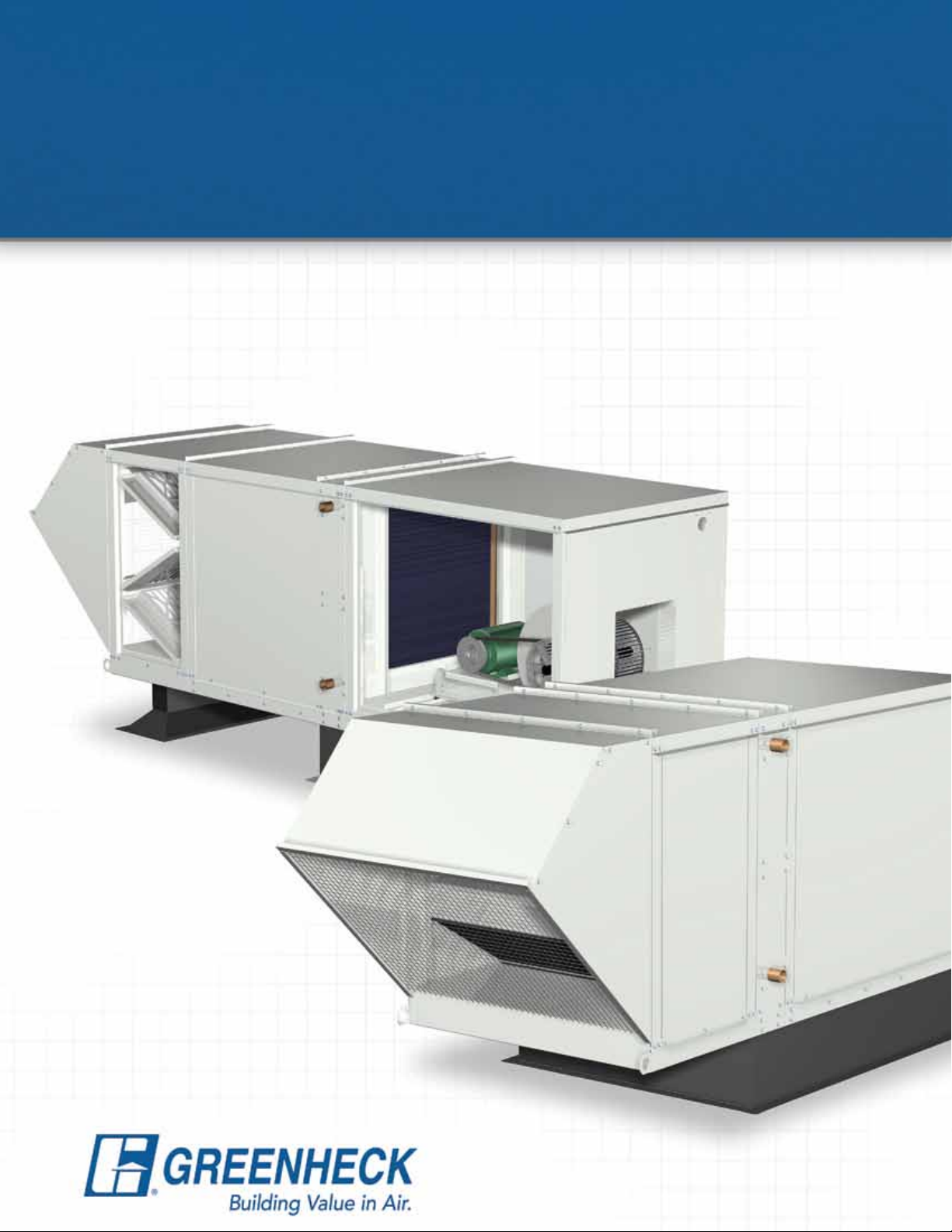
Modular Supply Make-Up Air Unit
Model MSX
• Flexible Design • Factory Assembled
Heating Options
• Hot Water
• Steam
• Electric
Cooling Options
• Evaporative
• Direct Expansion
• Chilled Water
November
2009
Page 2
Product Features
Model MSX
Modular Supply Unit
The Greenheck model MSX is an
ideal make-up air unit where gas-fired
heating is not desired. Coil heating
and/or cooling tempering options are
available with airflow volumes up to
48,000 cfm. The MSX may also be
used for untempered applications.
A flexible design concept enables
each product to be customized
for its application. Units are
factory assembled and wired to
minimize field installation labor.
The result is a semi-custom
product at an attractive cost.
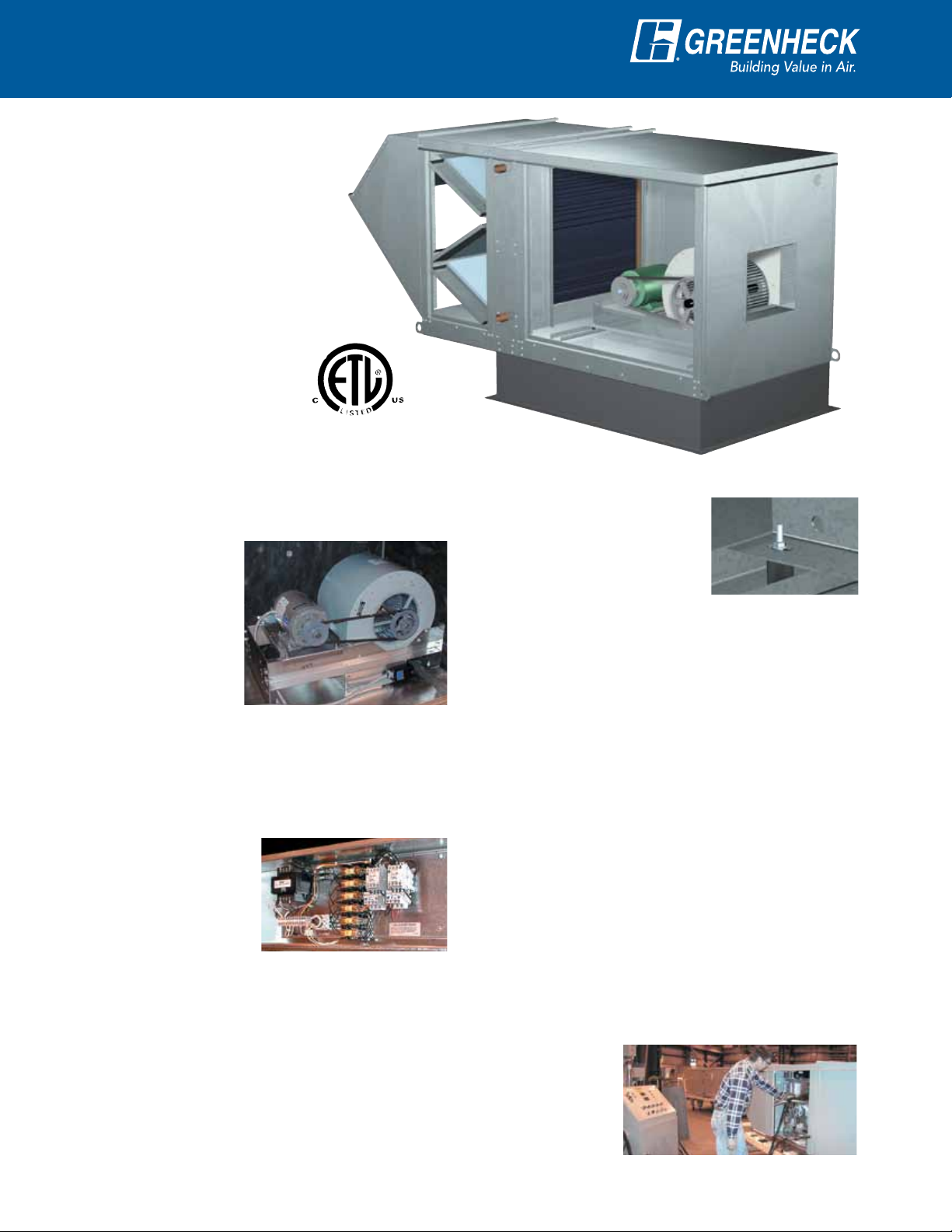
Reliable Fan Performance
Air performance ratings from Greenheck’s AMCA
registered test chamber ensure accurate data.
Double-width,
double inlet forward
curved wheels for
high efficiency and
low sound levels are
constructed of heavy
gauge steel. Wheels
are balanced to ensure
vibration free operation.
MSX shown with optional filter section,
hot water coil and horizontal discharge.
Vibration Isolators
The entire fan and motor
assembly is mounted on
vibration isolators to minimize
noise transmission to the
building. Spring isolators are
available in lieu of neoprene isolators.
Durable Construction
Designed for maximum weather resistance, MSX
housings are constructed of heavy gauge G90
galvanized steel. Lifting lugs are standard.
Control Center (Optional)
The control center includes the following standard
components:
•Magneticmotorstarterwithsolidstateoverload
protection
•Controltransformerwith
fusing
•Disconnectswitch
•Individualmotorfusing
•Distributionterminal
strip
Premium grade control components are selected for
reliable operation. All electrical components are UL
Listed, recognized or classified and factory prewired
for single point power connection.
2
Shafts
Shafts are precision turned, ground and polished steel
sized so that the first critical speed is at least 25%
over the maximum operating speed.
Bearings
Shafts rotate in permanently lubricated, heavy duty
ball bearings. Bearings are selected for a minimum
average (L10) life in excess of 100,000 hours at
maximum operation speeds.
Access Panels
Large access panels are provided for easy inspection
and maintenance of motors, drives, fan wheels, filters,
and heater controls.
Factory Wired and Tested
All units are tested
prior to shipment.
Units are checked
for proper fan and
controls operation.
Page 3
Tempering Options
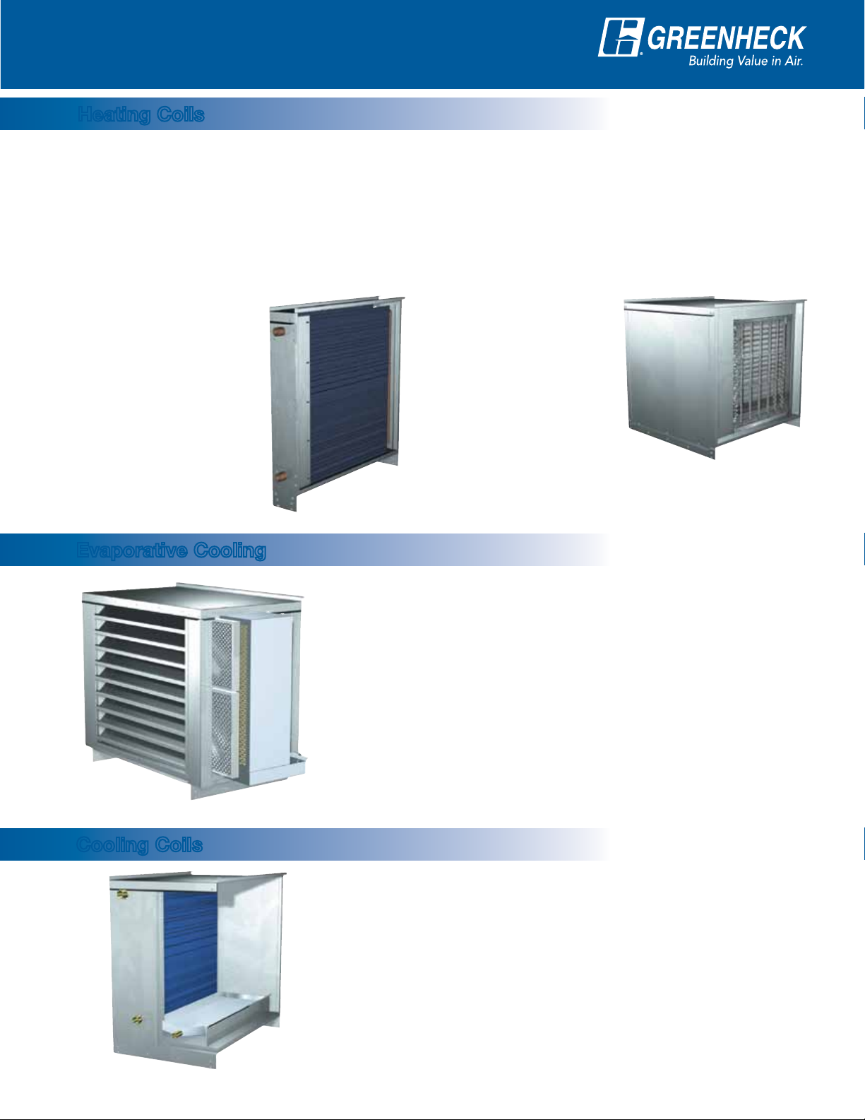
Heating Coils
Hot water, steam and electric heating is available with the model MSX. The heating section consists of the
heating coil factory installed in a pre-engineered coil housing. Water and steam coil connections are stubbed
through the wall for convenience.
For proper coil sizing, use Greenheck CAPS selection software or contact your local representative. All heating
options are available with airflow capacity up to 48,000 cfm.
The heating coil section is installed upstream of the fan section for a draw through arrangement and provide a
streamlined transition to adjacent MSX sections.
Hot Water and Steam
Hot water and steam
coils are available in
either a 100% thru-coil
airflow or face and bypass arrangement. Coils
have copper tubes with
permanently expanded
aluminum fins and are
tested and rated in
accordancewithAHRI410.
Evaporative Cooling
Electric Heat
Electric heaters are
UL Listed and feature
open coil heating
elements. Heater
control cabinets are
installed completely
within the heating
section, are factory
wired up to 200 kW and
meet all requirements
of the National Electric Code.
The evaporative cooling section includes a galvanized steel housing with
a louvered intake, 2-inch aluminum mesh filters and a stainless steel
evaporative cooling module. The evaporative cooling media is Munters
CELdek or GLASdek and has a depth of 12 inches for 90% cooling
effectiveness.
The entire section mounts directly to the front of the MSX unit,
eliminating transition or ductwork by others. Drain and overflow are
conveniently tapped through the side of the cooling section. The supply
line connection is field located where convenient. Freeze protection and
automatic drain & fill options are also available.
Cooling Coils
Airflow capacity for evaporative cooling is up to 48,000 cfm. The
evaporative cooling section for the housing size 32 through 42 ships
separately.
Chilled water or direct expansion (DX) cooling is available with the model
MSX. The cooling section includes the cooling coil, sloped stainless
steel drain pan and insulated double wall construction. Drain and coil
connections are stubbed through the wall for convenience.
For proper coil sizing, use Greenheck CAPS selection software or contact
your local representative. Four row and six row chilled water or DX coils
are available with airflow capacity up to 30,000 cfm.
Cooling coil sections are installed upstream of the fan section for a draw
through arrangement and provide a streamlined transition to adjacent
MSX sections. DX coils require remote condensing units.
3
Page 4

Options
Mixing Box
The mixing box option expands the make-up air application capabilities of the MSX. This section includes low
leakage control dampers for outdoor and return air and an actuator in
a face and bypass configuration. Either 2 inch pleated 30% filters or
2 inch aluminum mesh filters available within the mixing box section.
Double wall construction is available.
Greenheck offers three standard airflow control options with the MSX.
• Building Pressure Control: Outdoor air and return air dampers
modulate to maintain desired building pressure. Furnace control
is based on discharge temperature. A remote control panel with
photohelic gauge is required with this option.
• Potentiometer Control: Enables manual control of the outdoor air
and return air damper positions. A remote control panel is required
with this option.
• External Signal: Outdoor air and return air dampers modulate based
on an external 2-10 VDC or 4-20 mA signal.
Weatherhoods for MSX units with a mixing box include a mist eliminator to prevent moisture from entering the
mixing box section.
Arrangements
Downblast, Horizontal or Upblast Discharge
Model MSX is available in either downblast (Arrangement DB),
horizontal (Arrangement HZ), or upblast (Arrangement UB)
discharge.
Kitchen Combination Package
The Greenheck combination package simplifies
installation and reduces field labor costs for kitchen
ventilation systems. The pre-engineered design
ensures that the supply fan, exhaust fan, curb
and combination extension components interface
properly.
Equally important, Greenheck combination packages
are specifically designed to comply with NFPA 96.
NFPA 96 states:
• Exhaustductmustterminateatleast24inches
(610 mm) above the roof deck
• Fandischargemustbeatleast40inches
(1016 mm) above the roof deck
• Airintakeshallhaveahorizontalseparationof
10 feet (3.048 m) from the exhaust discharge
4
See Greenheck’s Series C catalog for complete
details on the model CUBE exhaust fan.
Note: Consult local codes and the authority having
jurisdiction if there are questions concerning
the use of this product.
Page 5

Accessories
Remote Control Panels
Industrialtyperemotecontrol
panels feature a variety of switches
and indicator lights mounted on a
Permatector™ coated galvaneal steel
box.Ifroomoverrideisspecified,
the override thermostat is factory
mounted on the remote panel as
shown at right.
Additional Accessories
Air Filter Gauge
The air filter gauge indicates when filters become
dirty. An indicator light may be wall/beam mounted or
provided with a remote control panel.
Motorized Dampers
Intakeordischargedampersareavailabletoprevent
backdraftswhenthefanisnotinoperation.Intake
dampers are factory mounted and wired.
Spring Vibration Isolation
Spring vibration isolators are available in lieu of
neoprene isolators.
Exhaust Fan Starter(s)
Exhaust fan starters may be added to the control
center.
Kitchen style remote
panels feature toggle
switches and a stainless
steel face plate for flush
mounting to a wall. The
junction box is also
included.
Freezestat
An on/off type discharge duct stat (with a timer)
prevents the discharge of cold air into the building
when the unit is not providing adequate tempering.
Equipment Supports
Factory provided equipment supports may be required
in addition to a roof curb, depending on the specified
unit configuration. Standard construction is G90
galvanized steel.
Special Coatings
Greenheck’s Permatector™ powder paint is available
if a painted look is desired. Decorative baked enamel
paints are also available in a variety of colors to match
existing building fixtures. Consult your Greenheck
representative for paint selections.
Inlet Air Sensor
An on/off type duct stat automatically de-energizes
the gas system and interrupts the flow of gas to the
burners when the inlet air temperature is above the
desired setting.
115 Volt GFCI Service Receptacle
A115voltGFCIoutletismountedexternallyina
NEMA-3R box for the convenience of field service
personnel. A separate 115 volt power source is
required.
Roof Curbs
Factory provided roof curbs are available to ensure
compatibility between make-up air unit and roof curb.
Standard construction is G90 galvanized steel.
2-Speed Motor
A 1⁄3 reduction 2-speed motor is available. Consult the
factory for 1⁄2 reduction 2-speed motor availability.
Smoke Detector
Photoelectric smoke detector is available for duct
mounting.
Fiberglass Insulation
Fiberglass insulation is used to line the housing to
prevent the formation of condensation and to form
anacousticalbarrier.Insulationisincludedforunits
specified with mixing box option.
Weatherhood
A galvanized steel weatherhood with birdscreen is
available. A mist eliminator is an optional weatherhood
accessory.
Duct Adapter
Duct adapter is available with factory supplied curbs
and allows an easy method for connecting ductwork to
curb.
Double Wall Construction
An interior metal liner is available to isolate insulation
from the airstream. One inch thick insulation is
included with this option.
Discharge Diffuser
Diffusers are available as either 3-way for horizontal
discharge or 4-way for downblast discharge.
5
Page 6

Air Performance
Housing Size 12
Blower
Size
108
109
110
Housing Size 22
Blower
Size
112
115
CFM
800
1,200
1,500
2,500
2,500
3,500
CFM
2,600
3,500
4,400
5,000
6,000
7,000
RPM 993 1109 1216 1311 1399 - -
BHP 0.21 0.26 0.31 0.35 0.40 - -
RPM 1238 1347 1445 1530 - - -
BHP 0.51 0.59 0.68 0.75 - - -
RPM 880 1014 1140 1255 1361 1460 -
BHP 0.36 0.45 0.54 0.63 0.73 0.84 -
RPM 1154 1244 1329 1419 1503 1587 -
BHP 1.1 1.2 1.4 1.6 1.7 1.9 -
RPM 906 995 1082 1166 1247 1325 1402
BHP 0.79 0.93 1.1 1.2 1.4 1.5 1.7
RPM 1131 1202 1275 1340 1401 1464 -
BHP 1.8 2.0 2.2 2.4 2.6 2.8 -
RPM 662 761 853 934 1009 - -
BHP .58 .72 .86 1.0 1.2 - -
RPM 756 839 920 993 1065 1133 1195
BHP 1.0 1.3 1.5 1.7 1.9 2.1 2.3
RPM 871 939 1006 1073 1137 1197 1254
BHP 1.8 2.1 2.4 2.6 2.9 3.1 3.3
RPM 671 741 808 871 931 986 1038
BHP 1.7 2.0 2.3 2.6 2.9 3.2 3.5
RPM 749 812 870 929 982 1035 1086
BHP 2.6 2.9 3.3 3.7 4.0 4.4 4.8
RPM 833 889 943 994 1044 1093 -
BHP 3.7 4.2 4.6 5.0 5.5 5.9 -
Total Pressure in inches wg
0.50 0.75 1.00 1.25 1.50 1.75 2.00
Total Pressure in inches wg
0.50 0.75 1.00 1.25 1.50 1.75 2.00
Housing Size 32
Blower
Size
118
120
Note: The air performance data shown does not include internal static pressure losses due to items such as filters, dampers and coils.
For exact air performance data based on specific unit configuration, use the Greenheck CAPS selection program.
6
CFM
7,000
8,500
10,000
10,000
12,500
15,000
0.50 0.75 1.00 1.25 1.50 1.75 2.00
RPM 566 627 685 738 790 839 885
BHP 2.1 2.5 2.8 3.2 3.6 4.0 4.4
RPM 636 690 740 790 836 880 923
BHP 3.3 3.8 4.2 4.7 5.1 5.6 6.1
RPM 712 759 805 849 891 933 -
BHP 5.0 5.5 6.1 6.6 7.1 7.7 -
RPM 542 590 634 678 723 765 803
BHP 3.6 4.0 4.5 5.0 5.6 6.1 6.6
RPM 633 672 711 748 784 820 855
BHP 6.3 6.9 7.5 8.1 8.7 9.3 10.0
RPM 731 763 795 829 861 892 -
BHP 10.2 10.9 11.6 12.3 13.1 13.8 -
Total Pressure in inches wg
Page 7

Air Performance
Housing Size 35
Blower
Size
122
125
CFM
15,000
17,000
19,000
19,000
21,000
23,000
Housing Size 38
Blower
Size
127
130
CFM
24,000
30,000
26,000
34,000
Total Pressure in inches wg
0.50 0.75 1.00 1.25 1.50 1.75 2.00
RPM 573 605 637 667 698 727 755
BHP 7.5 8.3 8.9 9.6 10.4 11.1 11.9
RPM 634 662 690 718 745 772 799
BHP 10.6 11.4 12.2 12.9 13.6 14.4 15.3
RPM 697 720 746 771 796 821 -
BHP 14.5 15.2 16.1 17.0 17.8 18.6 -
RPM 530 563 594 625 655 683 711
BHP 8.9 9.8 10.7 11.7 12.8 13.8 14.8
RPM 573 603 631 660 688 715 741
BHP 11.6 12.6 13.5 14.6 15.7 16.9 18.0
RPM 616 643 671 697 723 748 -
BHP 14.9 15.9 16.9 18.0 19.2 20.4 -
Total Pressure in inches wg
0.50 0.75 1.00 1.25 1.50 1.75 2.00
RPM 422 451 478 504 530 554 578
BHP 10.1 11.6 13.0 14.3 15.8 17.2 18.6
RPM 501 525 548 571 593 613 -
BHP 18.1 19.6 21.4 23.2 24.9 26.6 -
RPM 355 384 412 440 467 494 520
BHP 9.9 11.2 12.5 13.9 15.2 16.8 18.3
RPM 430 454 477 499 519 542 564
BHP 19.9 21.5 23.1 24.8 26.4 28.3 30.1
Housing Size 42
Blower
Size
133
136
Note: The air performance data shown does not include internal static pressure losses due to items such as filters, dampers and coils.
For exact air performance data based on specific unit configuration, use the Greenheck CAPS selection program.
CFM
0.50 0.75 1.00 1.25 1.50 1.75 2.00
RPM 343 371 397 422 446 467 488
32,000
BHP 14.0 15.7 17.5 19.2 21.0 22.6 24.3
RPM 401 426 448 470 491 512 531
40,000
BHP 25.0 27.1 29.1 31.5 33.7 35.8 37.9
RPM 385 405 426 445 464 482 499
42,000
BHP 25.6 27.7 29.8 32.0 34.1 36.3 38.5
RPM 429 447 465 483 500 517 -
48,000
BHP 36.7 39.0 41.5 44.0 46.4 48.9 -
Total Pressure in inches wg
7
Page 8

Specifications
General: Make-up air unit shall be as manufactured by
Greenheck Fan Corporation or approved equal provided
all specifications are met. Greenheck Model MSX is used
as the basis of design. Performance shall be as scheduled
on plans. All untempered and coil units shall be listed to
UL 1995.
Hot Water or Steam Coil: Coil shall be factory tested and
ratedinaccordancewithAHRI410.Coilsshallhavecopper
tubes with permanently expanded aluminum fins, 12 fpi or
less. Coil connections shall be stubbed out through the
make-up air unit housing wall.
Electric Heat: Electric heaters shall be UL Listed and
feature open coil heating elements. Heater control cabinets
shall be installed completely within the heating section and
be factory wired up to 200 kW and meet all requirements of
the National Electric Code. A separate power source shall
be provided for the electric heater.
Unit Casing and Frames: Unit shall be of internal frame
type construction of galvanized steel. All frames and
panels shall be G90 galvanized steel. Where top panels are
joined, there shall be a standing seam to insure positive
weather protection. All metal-to-metal surfaces exposed
to the weather shall be sealed, requiring no caulking at
jobsite. All components shall be easily accessible through
removable doors.
Insulation: Models provided with a mixing box shall be
insulated from the return section to the supply discharge.
Insulation shall be in accordance with NFPA 90A and
tested to meet UL 181 erosion requirements. Double wall
shall be provided if specified.
Fan Section: Centrifugal fans shall be double width,
double inlet. Fan and motor shall be mounted on a common
base and shall be internally isolated. All blower wheels
shall be balanced. Ground and polished steel fan shafts
shall be mounted in permanently lubricated ball bearings
(up to size 118) or ball bearing pillow blocks (size 120 and
larger). Bearings shall be selected for a minimum (L
in excess of 100,000 hours at maximum cataloged speeds.
Motors and Drives: Motors shall be energy efficient,
complying with EPACT standards, for single speed ODP
and TE enclosures. Motors shall be permanently lubricated,
heavy duty type, matched to the fan load and furnished at
the specified voltage, phase and enclosure. Drives shall be
sized for a minimum of 150% of driven horsepower. Pulleys
shall be cast and have machined surfaces, 10 horsepower
and less shall be supplied with an adjustable drive pulley.
Electrical: All internal electrical components shall be
prewired for single point power connection, excluding
electric heaters. All electrical components shall be
10
) life
UL Listed, recognized or classified
where applicable and wired in
compliance with the National Electrical
Code. Control center shall include
motor starter, control circuit fusing,
control transformer for 120 VAC
circuit, integral disconnect switch with
separate motor fusing and terminal
strip. Contactors, Class 20 adjustable
overload protection and single phase
protection shall be standard.
Filter Section: Filters shall be
mounted in a V-bank arrangement
such that velocities across the filters
do not exceed 550 feet per minute.
Filters shall be easily accessible
through a removable access panel.
Weatherhood: Weatherhood shall be
constructed of G90 galvanized steel
with birdscreen mounted at the intake.
Recirculation (optional): Recirculation airflow shall be
controlledbyadjustmentofreturndamperposition.Input
signal for return damper shall be from building pressure
sensors, potentiometer, external signal, or manual switch.
Recirculated air shall not be permitted to pass across the
burner. Return air shall be filtered.
Variable Volume (optional): Volume shall be varied
by either a 2-speed motor or variable frequency drive.
Inputsignalforfanspeedshallbefrombuilding pressure
sensors, potentiometer, external signal, or manual switch.
Cooling Coil: Direct expansion (DX) or chilled water
coil shall be factory tested and rated in accordance with
AHRI410.Coilsshallhavecoppertubeswithpermanently
expanded aluminum fins, 12 fpi or less. DX coils shall be
equipped with distributors to receive expansion valves at
the liquid connections. Drain pans shall extend at least
12 inches downstream of coil and be sloped to drain
connection.
Evaporative Cooling Section: Evaporative cooling
section shall include a galvanized steel housing with
louvered intake, 2-inch aluminum mesh filters and a
stainless steel evaporative cooling module all provided
by the make-up air unit manufacturer. The louver shall
be stationary type with drainable blades, designed to
withstand wind loads of 25 PSF. Evaporative cooling
media shall be Munters CELdek with a depth of 12 inches
for a cooling effectiveness of 90%. Drain and overflow
connections shall be piped through the side of the
evaporative cooling section.
Our Warranty
Greenheck warrants this equipment to be free from defects in material and workmanship for a period of
one year from the shipment date. Any units or parts which prove defective during the warranty period will
be replaced at our option when returned to our factory, transportation prepaid. Motors are warranted by the
motor manufacturer for a period of one year. Should motors furnished by Greenheck prove defective during
this period, they should be returned to the nearest authorized motor service station. Greenheck will not be
responsible for any removal or installation costs.
As a result of our commitment to continuous improvement, Greenheck reserves the right to change
specifications without notice.
Greenheck P.O. Box 410 • Schofield, WI 54476-0410 • Phone (715) 359-6171 • greenheck.com
Copyright © 2009 Greenheck Fan Corporation • MSX Rev. 2 November 2009 RG
Prepared to Support
Green Building Efforts
 Loading...