

Page 1
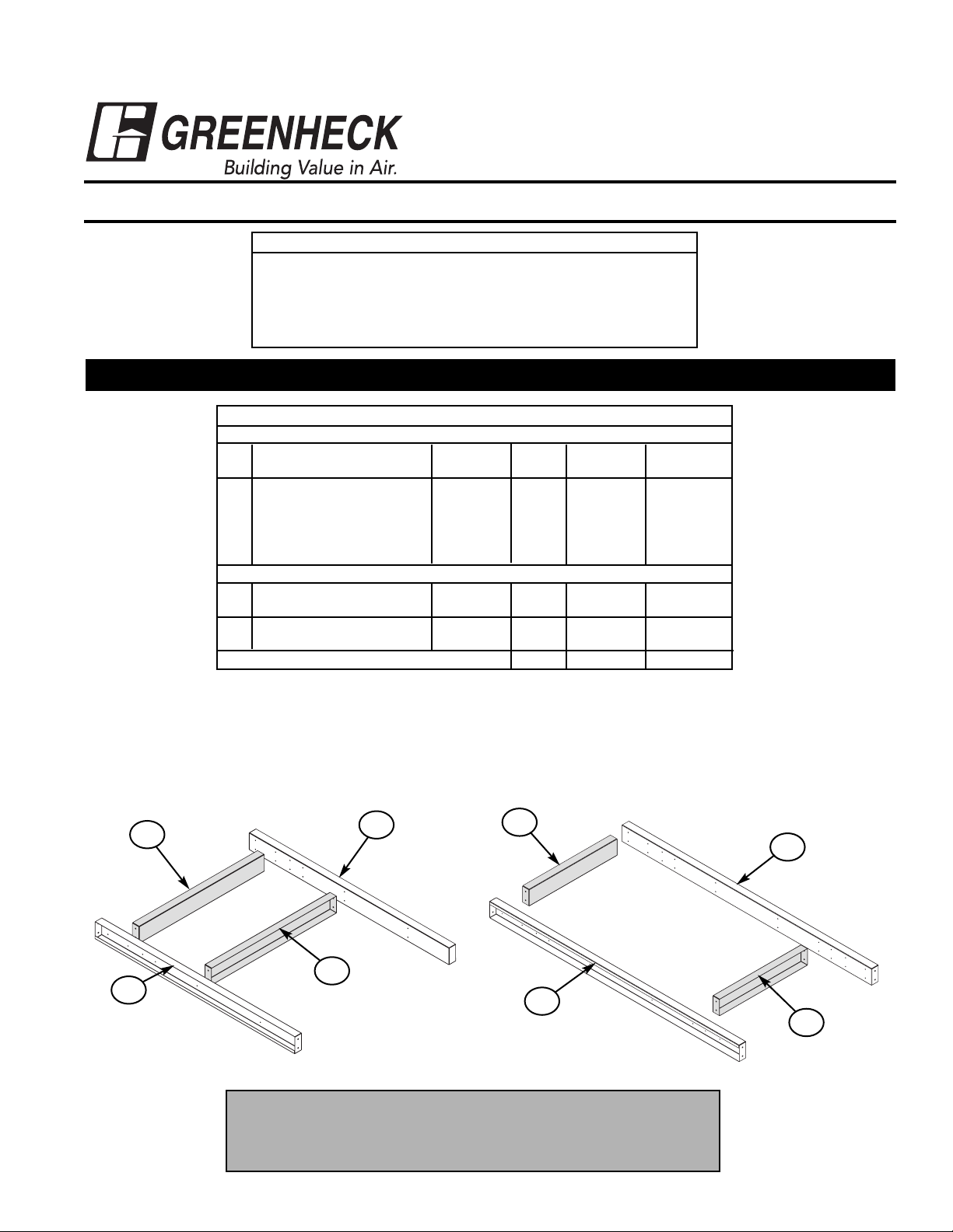
Figure 2: Recirc Duct Adapter
Part Description Height Qty P/N Length
Blower Curb Duct Adapter
A Duct Frame 12 2 709470 88.25 in.
24 2 709479 88.25 in.
B Duct Cross Channels
For blower 127 (Optional) 12 2 709473 36.75 in.
24 2 709476 36.75 in.
For blower 130 (Optional) 12 2 709474 39.50 in
24 2 709475 39.50 in.
Direct Gas Module Duct Adapter (Recirc)
A Recirc Frame 12 2 709470 88.25 in.
24 2 709479 88.25 in.
C Recirc Cross Channels 12 2 709471 26.75 in.
(Optional) 24 2 709478 26.75 in.
Hardware Kit 1 852310
April 2005
MAKE-UP AIR ROOF CURB
Model: MSU-38
ASSEMBLY INSTRUCTIONS
Table of Contents
Pg. 1 Duct Adapter Assembly (Optional)
Pg. 2 Blower Only Curb Assembly
Pg. 3 Blower & Direct Gas Module Curb Assmbly (Optional)
Pg. 3 Blower & Coil Curb Extension (Optional)
Pg. 4 Dimensional Data
B
Materials Required for Each Option:
(8 -12) SCREWS, SMS (A) 12 x 0.625 (IHH)
(Provided in Hardware kit)
Cordless drill with 5/16 in. nut driver.
Instructions:
• Align pre-drilled holes on parts,
indicated above, for selected option(s).
• Fasten together with screws provided.
NOTE:
Shaded parts in above drawings are optional. If specific unit does
not have such options refer to page 2 for additional instructions.
Please refer to page 4 for dimensional data.
B
A
A
A
A
C
C
Figure 1: Blower Duct Adapter
READ AND SAVE THESE INSTRUCTIONS
PART # 463290
DUCT ADAPTER PARTS LIST & ASSEMBLY
®
Page 2
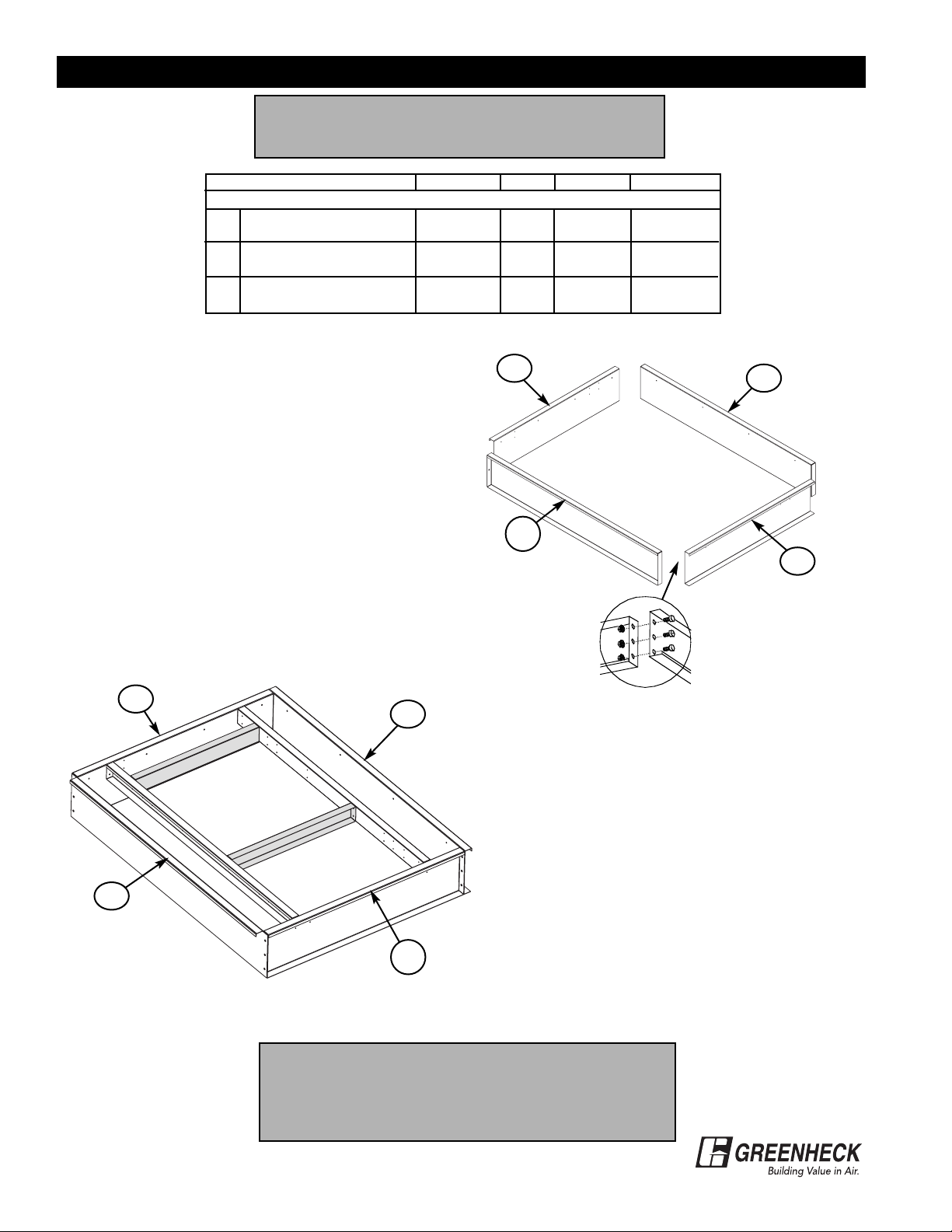
Figure 4: Blower Curb with Duct Adapter
2
BLOWER ONLY CURB PARTS LIST & ASSEMBLY
Part Description Height Qty P/N Length
Blower Curb Only
D End Channel 12 2 709468 92.00 in.
24 2 709481 92.00 in.
E Access Side 12 1 709472 64.25 in.
24 1 709486 64.25 in.
F Non-Access Side 12 1 709472 64.25 in.
24 1 709477 64.25 in.
NOTE:
If unit is equipped with Direct Gas Module or Coil
Section, please refer to page 3 for assembly instruction.
Materials Required for Assembly:
(12 - 24) 3/8 - 16 x 3/4 Serrated Flange Bolts
(12 - 24) 3/8 - 16 x 3/4 Serrated Flange Nuts
(8 - 12) SCREWS, SMS (A) 12 x 0.625 (IHH)
(Provided in Hardware kit)
Cordless drill with 9/16 in. nut driver
Cordless drill with 5/16 in. nut driver
Awl - for hole alignment
Combination 9/16 in.wrench
Instructions:
Figure 3
• Align pre-drilled holes.
• Fasten together with bolts provided.
Figure 4
• Fasten pre-assembled duct adapter to
the access & non access sides with screws
provided.
• Align pre-drilled holes.
• Fasten together with bolts provided.
Figure 3: Blower Curb Only
F
D
E
D
D
D
F
E
NOTE:
Figure 4 is shown with the Duct adapter option. Shaded
parts are not included unless specifically ordered.
Refer to Page 4 for dimensional data.
®
Page 3

Part Description Height Qty P/N Length
D End Channel 12 2 709468 92.00 in.
24 2 709481 92.00 in.
E Access Side 12 1 709472 64.25 in.
24 1 709486 64.25 in.
F Non-Access Side 12 1 709472 64.25 in.
24 1 709477 64.25 in.
G Center 12 1 709487 92.00 in.
24 1 709488 92.00 in.
H DGM Access Side 12 1 709469 58.00 in.
24 1 709480 58.00 in.
I DGM Non Access Side 12 1 709469 58.00 in.
24 1 709485 58.00 in.
Part Description Height Qty P/N Length
D End Channel 12 2 709468 92.00 in.
24 2 709481 92.00 in.
E Access Side 12 1 709472 64.25 in.
24 1 709486 64.25 in.
F Non-Access Side 12 1 709472 64.25 in.
24 1 709477 64.25 in.
G Center 12 1 709487 92.00 in.
24 1 709488 92.00 in.
J Coil Side 12 2 709504 13.00 in.
24 2 709503 13.00 in.
Materials Required for Assembly:
(18 - 36) 3/8 - 16 x 3/4 Serrated Flange Bolts
(18 - 36) 3/8 - 16 x 3/4 Serrated Flange Nuts
(16 - 24) SCREWS, SMS (A) 12 x 0.625 (IHH)
(Provided in Hardware kit)
Cordless drill with 9/16 in. nut driver
Cordless drill with 5/16 in. nut driver
Awl - for hole alignment
Combination 9/16 in. wrench
Instructions (refer to Figure 5):
• Fasten pre-assembled duct adapters (if
supplied) to the access & non access sides
with screws provided.
• Fasten access & non-access sides to the
Center with bolts provided.
• Align pre-drilled holes on curb corners.
• Fasten together with bolts provided.
Figure 6: Blower & Coil Extension Curb
Materials Required for Assembly:
Same materials required as Figure 5
Instructions (refer to Figure 6):
• Fasten pre-assembled duct adapter (if supplied) to
the access & non access sides with screws provided.
• Fasten access & non-access sides to the Center with
bolts provided.
• Align pre-drilled holes on curb corners.
• Fasten together with bolts provided.
I
G
F
D
D
H
E
D
D
J
E
J
G
F
BLOWER & DIRECT GAS MODULE CURB PARTS LIST & ASSEMBLY
3
BLOWER & COIL EXTENSION PARTS LIST & ASSEMBLY
Figure 5: Blower & Direct Gas Module Curb
NOTE:
Figures 5 & 6 are shown with Duct adapter & Recirc
adapter options. Shaded parts are not included
unless specifically ordered.
Refer to Page 4 for dimensional data.
®
Page 4

# 463290 MSU-38 Curb Assembly, rev 2
April 2005
Copyright © 2005 Greenheck Fan Corp.
D
Blower
Size
ABCD EFGHIJKLM
Dimensions for Blower and Direct Gas Curbs w/ Adapters (Figure 7)
127 92.25 66.375 60.125 126.50 26.75 71.00 28.75 17.50 36.75 37.50 13.00 18.00 36.75
130 92.25 66.375 60.125 126.50 26.75 71.00 28.75 17.50 39.50 37.50 13.00 15.50 39.25
Dimensions for Blower and Coil Curb Extension w/ Adapters (Figure 8)
127 92.25 66.375 14.875 81.25 18.00 37.50 36.75 13.00 36.75 n/a n/a n/a n/a
130 92.25 66.375 14.875 81.25 15.50 37.50 39.50 13.00 39.25 n/a n/a n/a n/a
Figure 7
A
G
H
E
F
K
I
J
M
L
C
B
D
Figure 8
C
B
A
H
G
F
D
E
Access Side
Blower
Discharge
Return Air
Access Side
DIMENSIONAL DATA
C
B
L
M
J
I
F
A
G
E
H
K
D
E
I
A
F
G
H
C
B
®
 Loading...