

Page 1
Document 476372
R
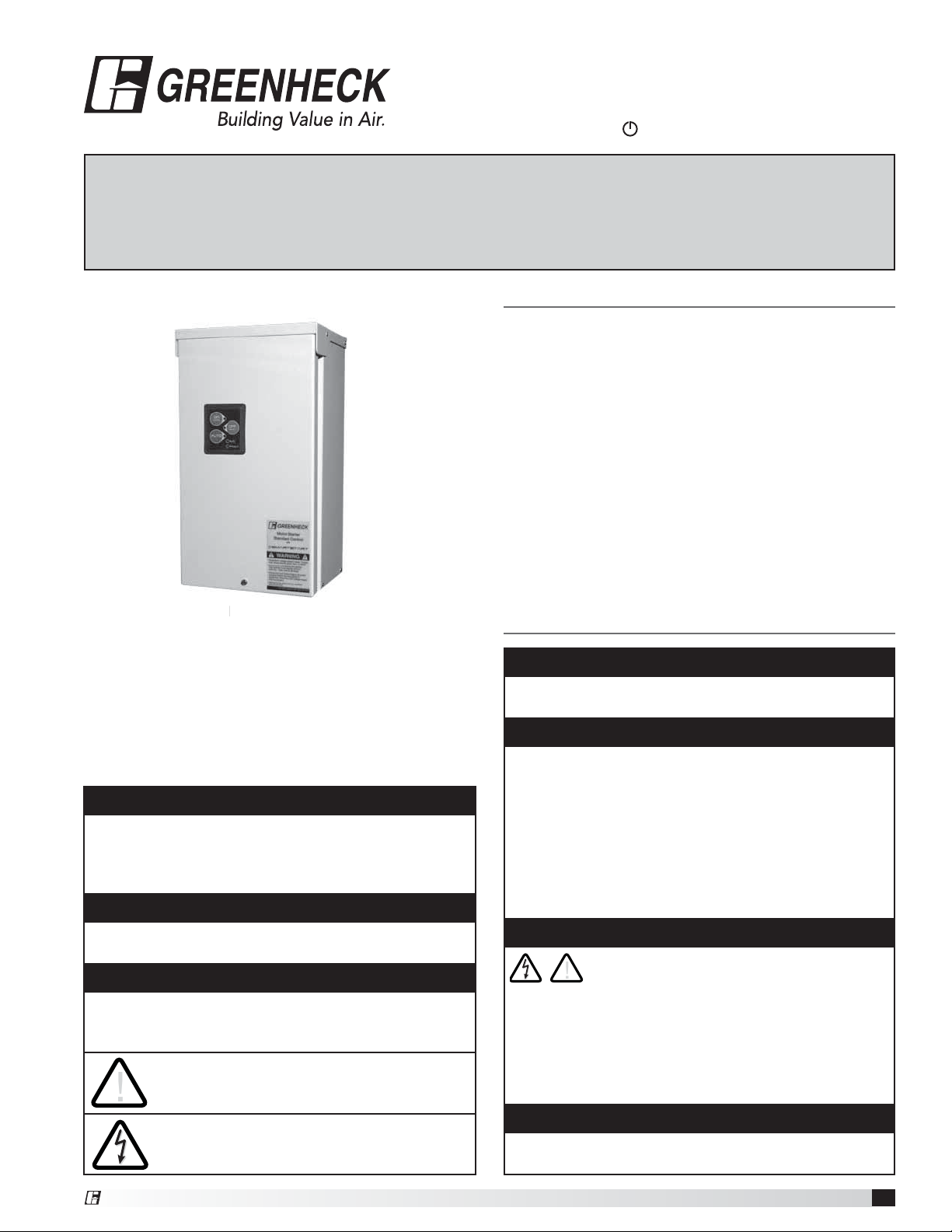
Model MSSC
®
Motor Starter Standard Control
with
smartstart
Installation, Operation and Maintenance Manual
Please read and save these instructions for future reference. Read carefully before attempting to assemble,
install, operate or maintain the product described. Protect yourself and others by observing all safety
information. Failure to comply with instructions could result in personal injury and/or property damage!
Table of Contents
Installation
Mounting ..................................2
Wiring ....................................2
Low Voltage Wiring ..........................2
Torque Table ...............................2
Wiring Schematic ............................2
Program Switches ...........................2
Protective Features ..........................3
Electronic Overload Operation .................3
Operation ..................................3
Keypad Interface. . . . . . . . . . . . . . . . . . . . . . . . . . . . 3
Operation Modes ...........................3
LED Status Indicators ........................3
I/O Descriptions .............................4
Our Commitment ............................4
NEMA 3R
3
16ga. Steel Enclosure
Safety Instructions
™
Precautions and Warnings
To prevent injury and property damage, follow these
instructions. Failure to adhere to installation/operation
procedures and all applicable codes may result in
hazards as indicated by warning codes outlined below:
DANGER
Indicates an imminently hazardous situation which,
if not avoided, will result in death or serious injury.
This signal word is to limited to the most extreme
situations.
WARNING
Indicates a potentially hazardous situation which, if
not avoided, could result in death or serious injury.
CAUTION
Indicates a potentially hazardous situtation which, if
not avoided, may result in minor or moderate injury. It
may also be used to alert against unsafe practices.
This is the safety alert symbol. Read and
!
follow instructions carefully to avoid a
dangerous situation.
This symbol alerts the user to the presence
of “dangerous voltage” inside the product
that might cause harm or electrical shock.
DANGER
Equipment can start automatically. Lockout/tagout
before servicing.
CAUTION
As with all electrical products, read manual
thoroughly. Only qualified, expert personnel should
perform maintenance and installation. Contact the
nearest authorized service facility for examination,
repair, or adjustment. Do not disassemble or repair
unit unless described in this manual; death or
injury to electrical shock or fire hazard may result.
Specifications and manual data subject to change.
Consult factory for additional information.
DANGER
HAZARDOUS VOLTAGE
!
• Disconnect and lock out all power before installing
or servicing equipment.
• This equipment may require locking out multiple
power sources prior to service.
• Install and wire in accordance with all applicable
local and national electrical and construction codes.
WARNING
FAILURE TO FOLLOW THESE INSTRUCTIONS
MAY RESULT IN DEATH OR SERIOUS INJURY.
®
Motor Starter Standard Control
1
Page 2
Installation
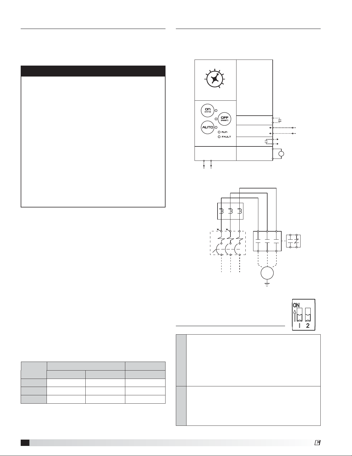
Wiring Schematic
Mounting
Mount the starter on a vertical surface, with the line
terminals facing up. Install using 1/4-inch diameter
hardware suitable for the mounting surface.
WARNING
• To maintain overcurrent and short circuit protection,
the manufacturer’s instructions for selecting current
elements and setting the instantaneous-trip circuit
breaker must be followed.
• Tripping of the instantaneous-trip circuit breaker
is an indication that a fault current has been
interrupted. Current-carrying components of the
magnetic motor controller should be examined and
replaced if damaged to reduce the risk of fire or
electric shock.
• Do not locate starter in an environment subject to
flammable gases, dusts or materials. Contact arcing
can induce explosion or fire.
• Locate starter in a location appropriate to enclosure
ratings and operational ratings. (e.g. NEMA-1 should
only be located in a dry, protected environment).
• Do not allow any metal shavings or debris from
installation to enter enclosure.
Wiring
Wire main power input and motor leads to the
appropriate terminals tightened to specified torques
indicated in the torque table. Use only copper
conductors rated at least 60°C for applications less
than 100A and at least 75°C ≥ 100A. Maintain proper
clearances and verify that no possibility of an electrical
short exists between the power conductors or
enclosure. Ensure that wires are not under stress and
all insulation is intact. Verify voltage input matches label
and the control power is tapped per schematic.
Standard product wiring diagram shown. As-built
product wiring may vary. Product wiring diagram located
on stater enclosure.
15
20
5
1
FLA (A)
Overload Setting
PCB Power
H1 H4
MCP
(Optional)
208-600VAC
Input
10
Keypad
208-600VAC
40VA Max.
OL
H1
25
30
35
40
H4
Dry
Input
Voltage
Input
Relay
Output
Contactor
Coil
L3L1 L2
Auto Run
Auto Run
M
T1 T3
MTR
3PH
Normally
Open Input
12-250VAC/DC Input
Status
24V
A1
Output to
M
A2
contactor coil
T2
24VDC output
to 24VAC
contactor coil
434431
32
AUX
CONT
Low Voltage Wiring
Automation system control wiring should be run in
a separate conduit. The control terminals accept
26~14AWG wire torqued to 3.5 in-lb.
Torque Table
NEMA
Size
00 15.6 18 20
0 15.6 18 20
1 15.6 18 20
Motor Starter Standard Control
2
Input (lb-in) Output (lb-in)
Standard Combination Motor Leads
Program Switches
Smartstart Bypass: Disables the Smartstart features
when on. Smartstart protects the motor by detecting
several common potentially damaging fault conditions.
When Smartstart is active, the starter will shut off under
the following conditions: if locked rotor condition is
present for 0.5 seconds, if the motor takes more than
SWITCH 1
10 seconds to start, or if the FLA setting is determined
to be incorrect.
(ON) - Fault reset: Depress the “OFF” button for
5 seconds to reset a fault trip. Starter will return to
“OFF” mode.
(OFF) - Automatic Fault Reset: The starter will make 3
attempts at an auto fault reset separated by 5 minutes
SWITCH 2
intervals. Also allows manual reset as above.
®
Page 3

Protective Features
Operation
Cycle
Fault
Short 24V
Locked
Rotor
Max Start
Time
Out of
Calibration
Trips when the starter is activated at a rate
exceeding 20 starts per minute.
Trips if the current drawn from the 24VDC
contactor coil terminals exceeds 1A.
Trips when a locked rotor condition is
detected for 0.5 seconds (Smartstart mode
only).
Trips if the motor takes more than 10 seconds
to start (Smartstart mode only).
Trips if the FLA setting is determined to be
incorrect based on the motor inrush current
(safety start mode only).
Trips if a STALL condition is detected. (0.5
Stall
seconds at 300% FLA and current slope not
decreasing). Disabled during startup.
Overload trip Class 10 or 20. Trip current =
115% of FLA. Trips when the load is greater
Overload
than the Full Load Ampere setting labeled
FLA- (1-40A). The trip time will be determined
by the Class 10/20 DIP switch.
Phase
Unbalance
Trips in the event of a phase failure or phase
unbalance greater than 70% (Smartstart
mode only)
Electronic Overload Operation
When an alarm occurs, the type of alarm will be
indicated by flashing a combination of the hand/off/auto
LED’s as indicated in the table.
• Intended for use with 3-Phase, 50/60Hz
• Accepts 208-600VAC, ±10%
• Short Circuit (RMS, Symmetrical)
Stand-Alone Overload Unit - 200 KAIC, 600V Max.
Standard Starter - 5 KAIC, 600V Max
Combination Starter - 100 KAIC, 240V Max.
30 KAIC, 480V Max.
10 KAIC, 600V Max.
• Ambient Operating Temperature = -20°C to 60°C
• Ambient Storage Temperature = -40°C to 85°C
Keypad Interface
15
10
5
1
FLA (A)
20
25
OFF ON
30
35
40
1
2
DRY
AUTO
AUTO
12-250V
V1 V2 D1 D2O1 O2
Fault Hand Off Auto
Cycle Fault Alarm - - -
Short 24V Alarm - - 0
Locked Rotor Alarm - 0 -
Max Start Time Alarm - 0 0
Out of Calibration Alarm 0 - -
Stall Alarm 0 - 0
Overload Alarm 0 0 -
Phase Unbalance Alarm 0 0 0
– = off 0 = on
* Run and Fault LED’s will blink together in the event of a
hardware fault.
DANGER
• Ensure that all connections are properly
!
torqued and enclosure is closed prior to
applying power to the device.
• Ensure all mechanical equipment operated by the
starter is clear for safe operation in case of starter
activation.
• When in AUTO mode, starter may be activated
remotely by the control system.
RELAY
STATUS
COIL
C- C+
CONTACTOR
Operation Modes
ON (HAND): Press the ON mode button to manually
engage motor.
OFF (RESET): Pressing the OFF mode button
manually disengages the motor. Additionally, the OFF
button serves as a manual Reset. Press and hold
OFF for 5 seconds to Reset the starter after a fault
trip.
AUTO: When utilizing AUTO mode, the starter is
controlled by a remote Start/Stop command.
LED Status Indicators
MODE LEDs: Illuminates with corresponding mode
selection (HAND/OFF/AUTO). Flashing mode LED
signals a fault trip during the last operating mode.
All three mode LEDs will flash simultaneously during
Shutdown or Fireman’s Override operation.
RUN LED: Illuminates when starter is given a Run
signal and proof of flow is detected. LED will flash
when Run signal is present without proof of flow to
motor.
FAULT LED: Illuminates upon a fault condition or
overload trip. Starter must be returned to the OFF
mode in order to Reset.
®
Motor Starter Standard Control
3
Page 4

I/O Descriptions
• Use 14-26AWG wire for I/O terminals
• Torque to 3.5 lb-in
Terminal Description
D1 / D2 Dry Auto Input: N.O. dry contact or
transistorized input. When closed, the starter will
operate when automatic mode is selected.
V1 / V2 Wet Auto Input: Accepts wetted customer
input. Input voltage must be within 12 - 250 VAC/
VDC (4.2mA maximum). Sending voltage to the
contact will operate the starter when in Auto
Mode.
File E242640
To conform to the EMC directive, a ferrite core is required on the input of the
starter module. Consult the factory for the recommended part number.
For a CE compliant installation, all electrical connections must be made by
a qualified electrician.
Terminal Description
O1 / O2 Status Relay Output: Normally open relay
contacts that close when the motor draws 60%
of the FLA current.
See below for Relay Output current ratings
120VAC, 0.6A
C- / C+ Contactor Output: Provides a 24V output to the
contactor when the motor starter is commanded
in either Hand or Auto mode. (Wired from mfg).
24V, 0.42A Max. for a Franklin Control Systems
contactor with 24VAC coil.
Our Commitment
As a result of our commitment to continuous improvement, Greenheck reserves the right to change specifications
without notice.
Specific Greenheck product warranties are located on greenheck.com within the product area tabs and in the
Library under Warranties.
Greenheck Motor Starter catalogs provides additional
information describing the equipment and specification data.
®
Phone: 715.359.6171 • Fax: 715.355.2399 • Parts: 800.355.5354 • E-mail: gfcinfo@greenheck.com • Website: www.greenheck.com
476372 • Motor Starter Standard Control, Rev. 3, November 2013 Copyright 2013 © Greenheck Fan Corporation
4
AMCA Publication 410-96, Safety Practices for Users and
Installers of Industrial and Commercial Fans, provides
additional safety information. This publication can be obtained
from AMCA International, Inc. at www.amca.org.
 Loading...