

Page 1
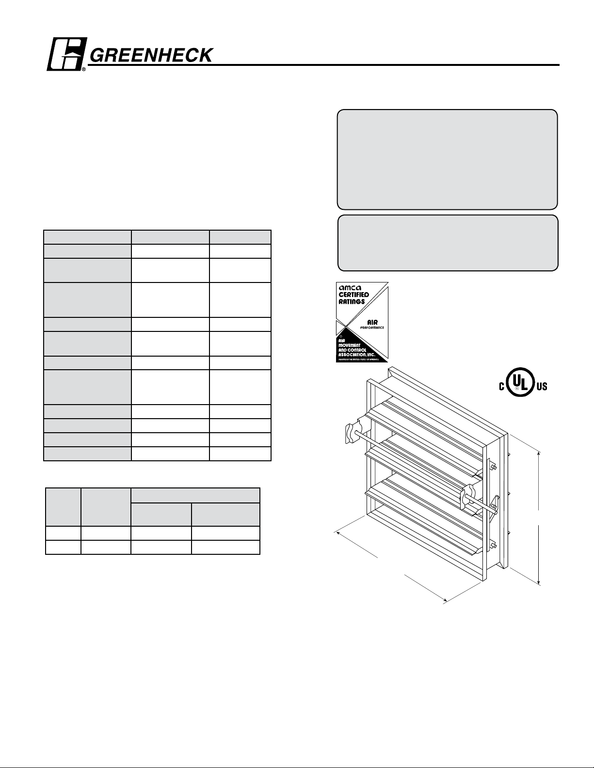
Model SMD-302M
H*
W*
APPLICATION
Model SMD-302M is a leakage rated modulating smoke damper
with class II leakage. The SMD-302M serves the function of both
a control damper and smoke damper. High strength airfoil blades
insure lowest resistance to airflow in HVAC systems with velocities
to 2000 fpm (10.2m/s) and 4 in. wg (1 kPa) Model SMD-302M may
be installed vertically (with blades running horizontal) or horizontally
and is rated for airflow and leakage in either direction.
UL 555S Leakage Rating
Leakage Class: II
Operational Rating
Maximum Velocity: 2000 fpm (10.2m/s)
Maximum Pressure: 4 in. wg (1 kPa)
Maximum Temperature: 250ºF (121ºC)
Construction Standard Optional
Frame Material Galvanized Steel -
Frame Material
Thickness
Frame Type
Blade Material Galvanized Steel -
Blade Material
Thickness
Blade Type Double Skin Airfoil -
Linkage
Axle Bearings Bronze 304SS
Axle Material Plated Steel -
Blade Seals Silicone -
Jamb Seals 304SS -
16 ga. (1.5mm) -
5 in. x 1 in.
(127mm x 25mm)
hat channel
14 ga. (2mm)
Equivalent
Plated Steel Out
of Airstream,
Concealed in Jamb
-
-
-
Smoke Dampers
Steel Airfoil Blades
UL 555S Leakage Class II
Model SMD-302M meets the requirements for
smoke dampers established by:
National Fire Protection Association
NFPA Standards 92A, 92B, 101 & 105
IBC International Building Codes
New York City (MEA listing #260-91-M)
CSFM California State Fire Marshal
Leakage (Smoke) Damper Listing (#3230-0981:104)
“UL CLASSIFIED (see complete marking on
product)”
“UL CLASSIFIED to Canadian safety standards
(see complete marking on product)”
Standard 555S (Listing #R13317)
Greenheck Fan Corporation certifies that the
model SMD-302M shown herein is licensed to
bear the AMCA Seal. The ratings shown are
based on tests and procedures performed in
accordance with AMCA Publication 511 and
comply with the requirements of the AMCA
R
Certified Ratings Programs. The AMCA Certified
Ratings Seal applies to air performance ratings
only.
Size Limitations
W x H
Inches 8 x 6 32 x 50 128 x 100
mm 203 x 152 813 x1270 3251 x 2540
Minimum
Size
Maximum Size
Single
Section
Multiple Section
OPTIONS:
• Factory mounted accessories
- Retaining angles
- Quick connect breakaway connections
- S & drive connections
- Access doors
• Greenheck test switches (GTS-3 & GTS-4)
• Momentary test switch
• POC retaining angles
• OCI (Open closed indication switches)
• Sealed transitions and sleeves
• Security bars
• Smoke detectors
• Transitions: R, C, O
LH
RH
*W&H dimensions furnished approximately 1/4 in. (6mm) undersize.
Right hand drive is shown. Left hand drive is available upon request.
Damper also may be rotated 180° in the field for opposite side drive.
(Add sleeve thickness for overall sleeved damper dimension)
Features:
• Frames are constructed with reinforced corners. Low profile
head and sill are used on sizes less than 17 in. high (432mm).
• Blades are double skin airfoil shape of galvanized steel with
full length structural reinforcement
• Actuators: 24V
Installation instructions available at www.greenheck.com
Page 2
Pressure Drop Data SMD-302M
5D 6D
5D
D
4 (W) (H)
3.14
5D 6D
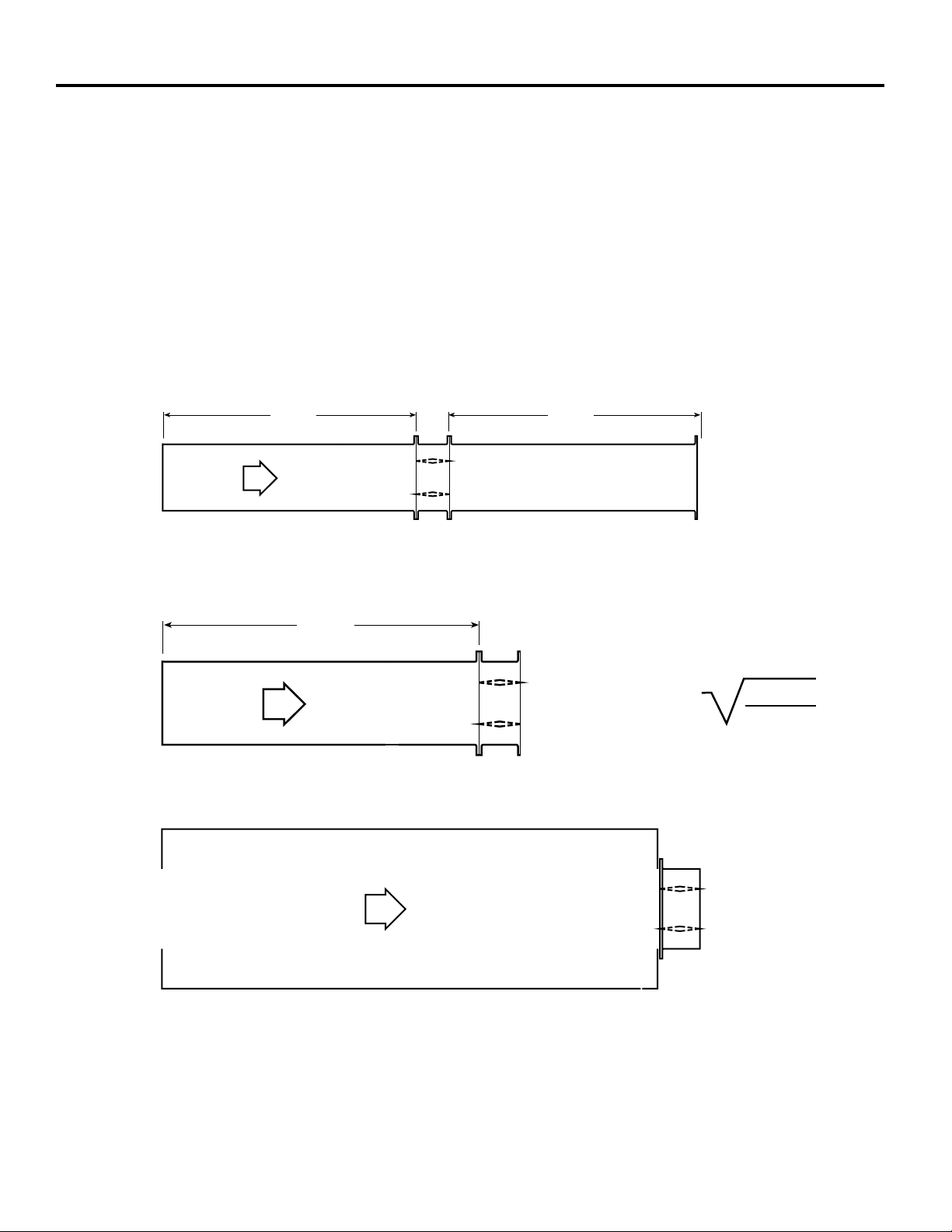
This pressure drop testing was conducted in accordance with AMCA Standard 500-D using the three configurations shown. All
data has been corrected to represent standard air at a density of .075 lb/ft3 (1.201 kg/m3).
Actual pressure drop found in any HVAC system is a combination of many factors. This pressure drop information along with an
analysis of other system influences should be used to estimate actual pressure losses for a damper installed in a given HVAC
system.
AMCA Test Figures
Figure 5.3 Illustrates a fully ducted damper. This configuration has the lowest pressure drop of the three test configurations
because entrance and exit losses are minimized by straight duct runs upstream and downstream of the damper.
Figure 5.2 Illustrates a ducted damper exhausting air into an open area. This configuration has a lower pressure drop than
Figure 5.5 because entrance losses are minimized by a straight duct run upstream of the damper.
Figure 5.5 Illustrates a plenum mounted damper. This configuration has the highest pressure drop because of extremely high
entrance and exit losses due to the sudden changes of area in the system.
5D 6D
Figure 5.3
5D
Figure 5.2
D
4 (W) (H
3.14
)
Figure 5.5
Page 3
12x12
48x12
24x24
36x36
12x48
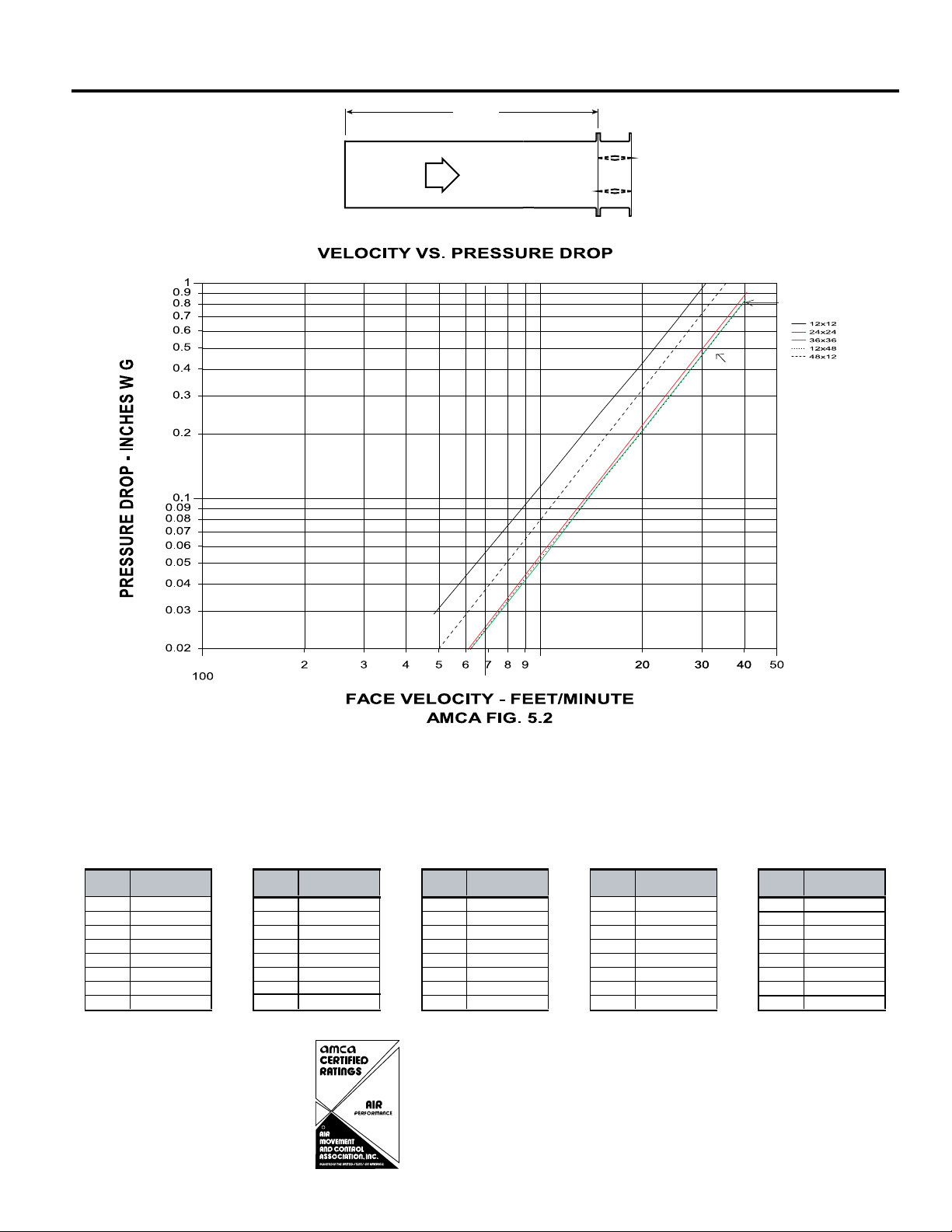
AMCA 5.2 Pressure Drop SMD-302M
5D 6D
D
4 (W) (H)
3.14
Velocity
(fpm)
Pressure Drop
(in. wg)
Velocity
(fpm)
Pressure Drop
(in. wg)
Velocity
(fpm)
Pressure Drop
(in. wg)
Velocity
(fpm)
Pressure Drop
(in. wg)
Velocity
(fpm)
Pressure Drop
(in. wg)
500 0.03 500 0.01 500 0.01 500 0.01 500 0.02
1000 0.12 1000 0.06 1000 0.06 1000 0.05 1000 0.08
1500 0.26 1500 0.12 1500 0.12 1500 0.12 1500 0.18
2000 0.46 2000 0.22 2000 0.22 2000 0.21 2000 0.33
2500 0.72 2500 0.34 2500 0.34 2500 0.33 2500 0.51
3000 1.04 3000 0.49 3000 0.49 3000 0.48 3000 0.74
3500 1.41 3500 0.67 3500 0.67 3500 0.65 3500 1.00
4000 1.84 4000 0.87 4000 0.88 4000 0.85 4000 1.31
12in. X 48 in.
(
305mm x 1219mm) 48 in. x 12 in. (1219mm x 305mm) 24 in. x 24 in. (610mm x 610mm) 36in. x 36 in. (914mm x 914mm) 12 in. x 12 in. (305mm x 305mm)
5D
* Sizes are in inches.
Greenheck Fan Corporation certifies that the
model SMD-302M shown herein is licensed
R
to bear the AMCA Seal. The ratings shown
are based on tests and procedures performed
in accordance with AMCA Publication 511
and comply with the requirements of the
AMCA Certified Ratings Programs. The
AMCA Certified Ratings Seal applies to air
performance ratings only.
Page 4

12x12
48x12
12x48
24x24
36x36
AMCA 5.3 Pressure Drop SMD-302M
Velocity (fpm)
Pressure Drop
(in. wg) Velocity (fpm)
Pressure Drop
(in. wg) Velocity (fpm)
Pressure Drop
(in. wg) Velocity (fpm)
Pressure Drop
(in. wg) Velocity (fpm)
Pressure Drop
(in. wg)
500 0.01 500 0.01 500 0.01 500 0.01 500 0.01
1000 0.06 1000 0.02 1000 0.02 1000 0.02 1000 0.04
1500 0.13 1500 0.06 1500 0.05 1500 0.06 1500 0.10
2000 0.23 2000 0.10 2000 0.09 2000 0.10 2000 0.18
2500 0.37 2500 0.16 2500 0.14 2500 0.16 2500 0.29
3000 0.53 3000 0.23 3000 0.21 3000 0.24 3000 0.42
3500 0.73 3500 0.32 3500 0.29 3500 0.33 3500 0.57
4000 0.95 4000 0.42 4000 0.38 4000 0.43 4000 0.74
24 in. x 24 in.
(
610mm x 610mm)36in. x 36 in. (914mm x 914mm
)
12in. X 48 in. (305mm x 1219mm)48 in. x 12 in. (1219mm x 305mm
)
12 in. x 12 in. (305mm x 305mm
)
5D 6D
* Sizes are in inches.
R
Greenheck Fan Corporation certifies that the
model SMD-302M shown herein is licensed
to bear the AMCA Seal. The ratings shown
are based on tests and procedures performed
in accordance with AMCA Publication 511
and comply with the requirements of the
AMCA Certified Ratings Programs. The
AMCA Certified Ratings Seal applies to air
performance ratings only.
Page 5

12x12
48x12
24x24
12x48
36x36
AMCA 5.5 Pressure Drop SMD-302M
5D 6D
5D
D
4 (W) (H)
3.14
Velocity
(fpm)
Pressure Drop
(in. wg)
Velocity
(fpm)
Pressure Drop
(in. wg)
Velocity
(fpm)
Pressure Drop
(in. wg)
Velocity
(fpm)
Pressure Drop
(in. wg)
Velocity
(fpm)
Pressure Drop
(in. wg)
500 0.04 500 0.03 500 0.03 500 0.03 500 0.03
1000 0.18 1000 0.13 1000 0.12 1000 0.12 1000 0.14
1500 0.42 1500 0.29 1500 0.27 1500 0.27 1500 0.32
2000 0.75 2000 0.52 2000 0.48 2000 0.49 2000 0.57
2500 1.17 2500 0.81 2500 0.75 2500 0.77 2500 0.89
3000 1.68 3000 1.17 3000 1.08 3000 1.11 3000 1.28
3500 2.29 3500 1.60 3500 1.48 3500 1.51 3500 1.75
4000 2.09 4000 2.14 4000 1.93 4000 1.97 4000 2.29
24 in. x 24 in. (610mm x 610mm)36in. x 36 in. (914mm x 914mm
)
12in. X 48 in. (305mm x 1219mm)48 in. x 12 in. (1219mm x 305mm
)
12 in. x 12 in. (305mm x 305mm
)
R
Greenheck Fan Corporation certifies that the
model SMD-302M shown herein is licensed
to bear the AMCA Seal. The ratings shown
are based on tests and procedures performed
in accordance with AMCA Publication 511
and comply with the requirements of the
AMCA Certified Ratings Programs. The
AMCA Certified Ratings Seal applies to air
performance ratings only.
Page 6

Application Data
53/8"
5"
Right hand drive is shown
Left hand drive available upon request
LH RH
A
Sleeve Length
Varies
6"
33/4"
11/2" max.
53/8 in.
5 in.A
Sleeve Length
Varies
33/4 in.
1
1
/2 in. max.
Damper Sideplate and Sleeve Dimensional Data
The drawings below illustrate the factory standard sideplate and sleeve mountings for the SMD-302M. The standard "A"
dimensions listed in the table provide adequate space for the mounting of actuators and controls.
If space constraints are a problem the "A" dimension can be varied between 53/8 in. (136mm) and 12 in. (305mm).
Sideplate
6 in.
5 in.
A
12 in.**
S
"A" Dimension
in. (mm)
Standard Maximum
Sleeve
Sideplate
All Dampers* 7 3/16 (183) 12 (305) 6 3/16 (157)
When height is
11 in. (279) or
11 3/16
(284)
12
(305)
10 3/16
(259)
less with OCI
*With the exception of dampers 11 in. (279mm) high or less (12 in.
(305mm)high or less if width is greater than 64 in. (1625mm)) with OCI
option.
** On dampers 11 in. (279mm) high or less (12 in. (305mm)high or less if
width is greater than 64 in. (1625mm)) with OCI option, sideplate is 16 in.
(406mm)
T*
Space Envelopes Required for Actuators
and Accessories
Externally mounted actuators always require space outside
of the damper sideplate or sleeve. The “S” dimension
illustrates the clearance required for various available
actuators.
On dampers less than 18 in. (457mm) high, actuators
may also require clearances above and/or below the
sideplate or sleeve. “B” and “T” dimensions are worst case
clearance requirements for some dampers less than 18
in. (457mm) high. All damper sizes under 18 in. (457mm)
high do not require these worst case clearances. If space
availability above or below the damper sleeve is limited,
each damper size should be individually evaluated.
Varies
Sleeve
A
11/2" max.
33/4"
53/8"
5"
Sleeve Length
Actuator Type/Model
MS7520A2015/B
MS7520A2213/B
* For dampers 18 in. (457mm) or more in height these dimensions are 0 in.
With OCI, RRL,
B*
B* T*
or TOR
With OCI, RRL,
or TOR
S
24 Volt AC
6 in. (152mm) 3/8 in. (10mm) 6 in. (152mm)
Page 7

50 in.
96 in. (2435mm)
(1270mm)
32 in. (813mm)
Damper Sizing Information
D* +
2 in. (51mm) +T
s
D*
TYPE R
16 in. (406mm)
Min.
2 1 / 8 in.
D* + 2 in. (51mm)+T
s
TYPE O
W
*
H*
W*
+ 2 in. (51mm)+T
s
H* + 2 in. (51mm)+T
s
W*
H*
TYPE C
H* + 2 in. (51mm)+T
s
(54mm)
16 in. (406mm)
Min.
2 1 / 8 in.
(54mm)
16 in. (406mm)
Min.
W* + 2 in. (51mm)+T
s
(54mm)
2 1 / 8 in.
Dampers larger than maximum single section size are supplied as a factory assembly of two or more sections of equal size.
The following figures show damper sections and assemblies that have been qualified for operation with a single actuator.
Larger sizes can be accommodated using multiples of these assemblies.
Double Section
Single Section
50 in.
50 in.
(1270mm)
(1270mm)
32 in. (813mm)
Transitioned Damper
Dimensions
When a fire/smoke damper is being used in conjunction with round or oval ductwork, the
SMD-302M can be supplied in a factory sleeve with round or oval transitions on both ends of
the sleeve. Dampers should be ordered to the duct dimensions. Drawings below show overall
damper size.
Specifications
Smoke Dampers meeting the following specifications shall
be furnished and installed where shown on plans and/or as
described in schedules. Dampers shall meet the requirements of NFPA 92A, 92B, 101, and 105 and further shall
be tested, rated and labeled in accordance with the latest
edition of UL Standard 555S. Smoke dampers shall be of low
leakage design qualified to UL 555S Leakage Class II.
Each damper /actuator combination shall have a UL555S
elevated temperature rating of 250°F (121º C) minimum and
shall be rated to operate at maximum design air flow at its
installed location. Each damper shall be supplied with an
appropriate actuator installed by the damper manufacturer
at the time of damper fabrication. Damper actuator shall be
(specifier select one of the following) electric type for 24 Volt
operation.
Damper blades shall be of the double skin airfoil type and
32 in. (813mm)
64 in. (1626mm)
These dimensions are furnished
*
approximately
except round and oval dimensions
which are approximately
undersize.
Ts = (2)(Sleeve Thickness)
1
/4 in. (6mm) undersize,
1
/8 in. (3mm)
shall have an equivalent metal thickness of 14 ga. (2mm)
Damper frame shall be galvanized steel formed into a structural hat channel shape with reinforced corners. Bearings
shall be sintered bronze sleeve type rotating in extruded
holes in the damper frame. Blade edge seals shall be silicone rubber designed to inflate and provide a tighter seal
against leakage as pressure on either side of the damper
increases. Jamb seals shall be stainless steel compression
type with silicone rubber backing. Blades shall be completely symmetrical relative to their axle pivot point, presenting
identical resistance to airflow in either direction or pressure
on either side of the damper.
Damper must be rated for mounting vertically (with blades
running horizontal) or horizontally and be UL 555S rated for
leakage and airflow in either direction through the damper.
The basis of design is Greenheck Model SMD-302M.
Copyright ©2009 Greenheck Fan Corporation
SMD-302M Rev. 7 April 2009
 Loading...