

Page 1
DOCUMENT NUMBER 479869
®
MOUNTING KIT FOR ACTUATORS
Belimo and Honeywell models
Installation, Operation, and Maintenance Instructions
These instructions apply to the internal or external field replacement of mounting hardware for direct drive
actuators (Belimo and Honeywell [except MS7505 and MS8105 series] ) on Greenheck control dampers when
they are duct mounted or sleeved.
WARNING
!
Equipment Damage or Electrical Power Hazard.
Line voltage can cause death or serious injury
and short circuit equipment. Disconnect power
supply before installation.
Wrenches: (1)
(1) Ratchet with
(1) Drill with 3⁄8 in. and 9/32 in. nut driver,
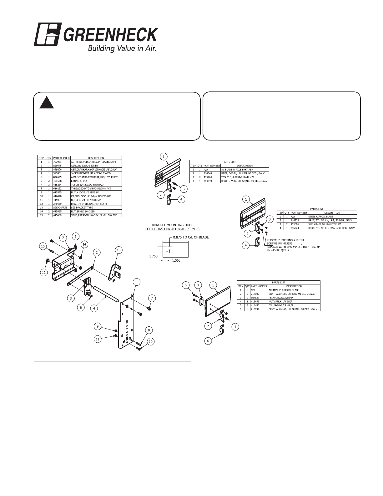
PART NO. 872700: INTERNAL MOUNT - 1/2 IN. PIN OR JACKSHAFT
3-V Blade
Tools Required:
7
⁄16 in., (1) 3⁄8 in., (1) 9⁄16 in.
3
⁄8, 7⁄16, 9⁄16 in. deepwell socket
(1) 1⁄8 in. Allen wrench,
(1) .203 dia. drill bit
Steel Airfoil Blade
Instructions
1. Have damper in desired fail position.
2. Drill (2) 0.203 inch holes in the first blade (when one
or two blade damper) or third blade (more than a two
blade damper) at a location as shown above for the
blade type you have.
3. Attach blade drive lever (item #13) using two fasteners
(see list above based on blade type). Note: Shaft (item
#4) needs to be centered with the centerline of the
blade.
4. Fasten actuator bracket (item #1) to the left jamb of
damper frame using (1) thread cutting screw in top tab
of bracket (0.203 in. hole is required). Note bottom tab
does not get a fastener. Install (2) 1/4 -20 x 1/2 studs
(item #15) and nuts (item #14) through holes in damper
Aluminum Airfoil Blade
frame. Snap bearing (item #12) into internal actuator
bracket.
5. Slide 1/2 in. diameter shaft (item #4) slightly through
the anti-rotation bracket (item #5). Install crankarm
(item #3) and drive link (item #2) onto the 1/2 in.
diameter shaft (item #4) and install e-clip (item #6) to
lock drive link (item #2) on the crankarm (item #3).After
the crankarm is installed, slide 1/2 in. shaft through the
bearing (Item #12).
6. Install shoulder bolt (items #8 or 10) to the anti-rotation
bracket (item #5) using nut (item #9 or 11). Bolt
location will vary depending on the actuator model.
7. Slide the anti-rotation bracket (item #5) over the 1/2
in. shaft. Fasten to actuator bracket (item #1) using
thread cutting screws (item #7). Attach actuator to
Page 2
PART NO. 872700 INSTRUCTIONS CONT...
anti-rotation bracket assembly (item #5). Tighten the
actuator onto the shaft (item #4).
8. Connect drive link (item #2) to blade drive lever (item
#13) using e-clip (item #6). For fail close, position the
blades in the closed position and the actuator in its fail
position. For fail open, position the blades in the open
position and the actuator in its fail position. Tighten
the crankarm to the 1/2 in. shaft.
9. Connect all electrical leads to the actuator. Apply
power to the actuator. The damper blades should
rotate to the power position and return to the fail
position when power is disconnected.
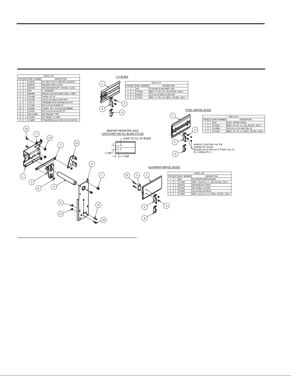
PART NO. 872701: INTERNAL MOUNT FOR 1 IN. JACKSHAFT
Instructions
1. Have damper in desired fail position.
2. Drill (2) 0.203 inch holes in the first blade (when one
or two blade damper) or third blade (more than a two
blade damper) at a location as shown above for the
blade type you have.
3. Attach blade drive lever (item #12) using two fasteners
(see list above based on blade type). Note: Shaft
needs to be centered with the centerline of the blade.
4. Fasten actuator bracket (item #1) to the left jamb of
damper frame using (1) thread cutting screw in top tab
of bracket (0.203 in. hole is required). Note: bottom tab
does not get a fastener. Install (2) 1/4 x 20 x 1/2 stud
bolts (item #14) and nuts (items 13) through the frame.
5. Slide 1 in. diameter shaft (item #4) slightly through the
anti-rotation bracket (item #5). Install crankarm (item
#3)and drive link (item #2) onto the 1 in. diameter shaft
(item #4) and install e-clip (item #6) to lock drive link
(item #2) on the crankarm.
2
6. Install shoulder bolt (item #8 or 10) to the anti-rotation
bracket (item #5) using nut (item #9 or 11). Bolt
location will vary depending on the actuator model.
7. Install anti-rotation bracket (item #5) to actuator
bracket (item #1) using thread cutting screws (item #7).
Attach actuator to anti-rotation bracket assembly (item
#5). Tighten the actuator onto the shaft.
8. Connect drive link (item #2) to blade drive lever (item
#12) using e-clip (item #6). For fail close, position the
blades in the closed position and the actuator in its fail
position. For fail open, position the blades in the open
position and the actuator in its fail position. Tighten
the crankarm to the 1/2 in. shaft (item #4).
9. Connect all electrical leads to the actuator. Apply
power to the actuator. The damper blades should
rotate to the power position and return to the fail
position when power is disconnected.
Page 3

PART NO. 872907: EXTERNAL MOUNT DIRECT DRIVE
Instructions
1. Have damper in desired fail position.
2. Install clip (item #4) into extension pin (item #1). Push
extension pin onto drive blade (bottom blade for
dampers with one or two blades) or third blade (when
damper has more than two blades).
3. Mount the stand-off bracket (item #2) over the
extension pin (item #1) spanning across the damper
frame. Fasten to the damper frame with bolts and nuts
(items 5 & 6).
4. Fasten the actuator bracket (item #3) to the standoff
bracket using bolts and nuts (items #5 & 6).
5. Install shoulder bolt (item #7 or 8) to the anti-rotation
bracket (item #3) using nut (item #9 or 10). Bolt
location will vary depending on the actuator model.
6. For fail close, position the blades in the closed
position and the actuator in its fail position. For fail
open, position the blades in the open position and the
actuator in its fail position. Tighten the actuator clamp
to the damper pin (item #1).
7. Attach actuator to anti-rotation bracket assembly (item
#3). Tighten the actuator onto the shaft (item #1).
8. Connect all electrical leads to the actuator. Apply
power to the actuator. The damper blades should
rotate to the power position and return to the fail
position when power is disconnected.
3
Page 4

PART NO. 872908: EXTERNAL MOUNT JACKSHAFTED
Instructions
1. Have damper in desired fail position.
2. Jackshaft supplied is 1 in. (25mm) diameter or 1/2 in.
(13mm) diameter. Mount the stand-off bracket (item #3)
with thread cutting screws (item #5). Orient the standoff bracket (item #3) so the hole is centered on the
jackshaft.
3. Fasten the actuator bracket (item #4) to the standoff
bracket using thread cutting screws (item 5). Use outer
four holes of the actuator bracket.
5. Install shoulder bolt (item #6 or 7) to the anti-rotation
bracket (item #3) using nut (item #8 or 9). Bolt location
will vary depending on the actuator model.
4. For fail close, position the blades in the closed
position and the actuator in its fail position. For fail
open, position the blades in the open position and the
actuator in its fail position. Tighten the actuator clamp
to the jackshaft (item #1).
5. Attach actuator to anti-rotation bracket assembly
(item #4). Tighten the actuator onto the shaft (item #1).
6. Connect all electrical leads to the actuator. Apply
power to the actuator. The damper blades should
rotate to the power position and return to the fail
position when power is disconnected.
Our Commitment
As a result of our commitment to continuous improvement, Greenheck reserves the right to change
specifications without notice.
Specific Greenheck product warranties are located on greenheck.com within the product area tabs and in
the Library under Warranties.
®
Phone: (715) 359-6171 • Fax: (715) 355-2399 • E-mail: gfcinfo@greenheck.com • Website: www.greenheck.com
479869• Mounting Kits for Actuators Rev. 1, January 2015 Copyright 2015 © Greenheck Fan Corporation
4
 Loading...