

Page 1
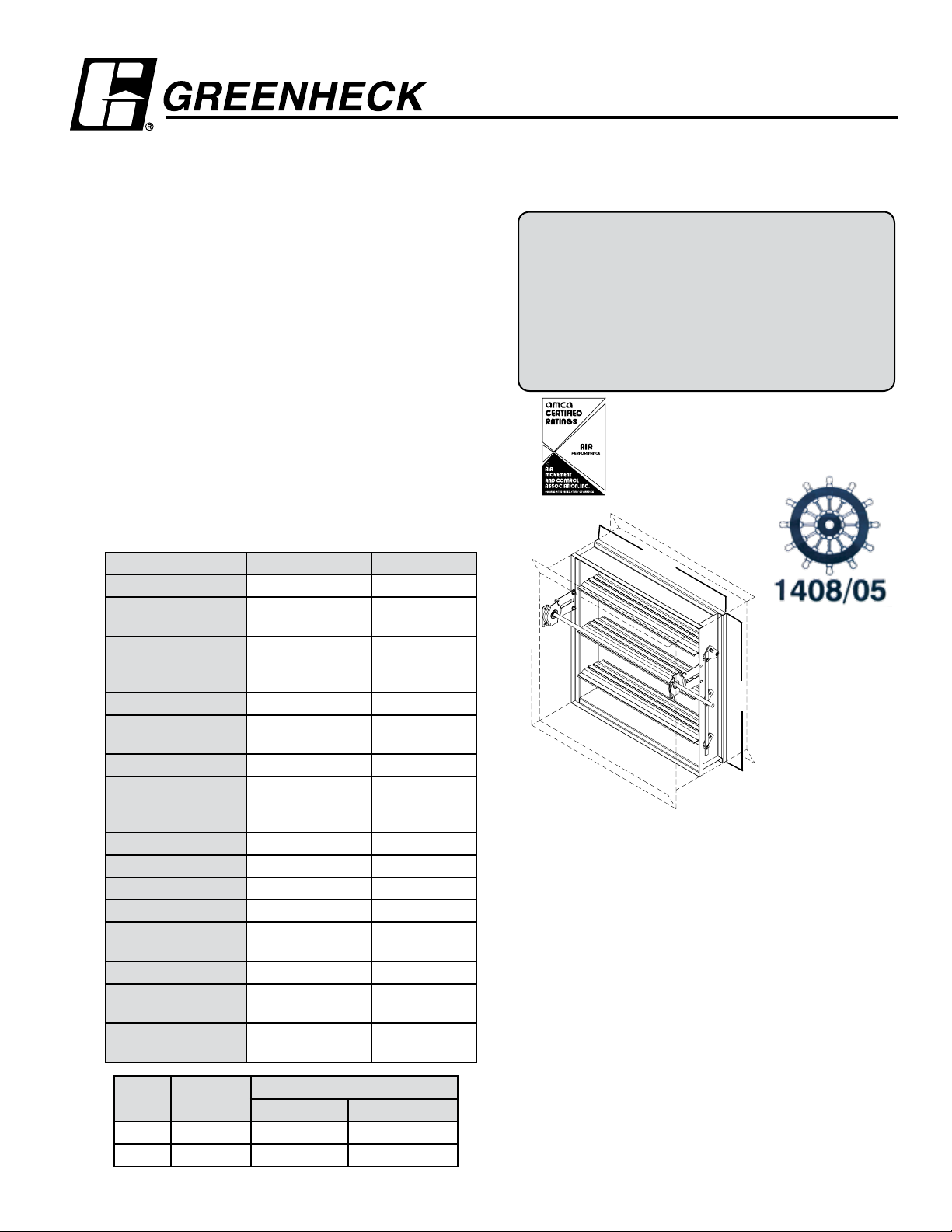
Model SSIMO-311
APPLICATION
Combination Fire Smoke Marine Damper
Model SSIMO-311 is a high performance combination fire smoke
damper with extremely low leakage designed for marine application.
High strength airfoil blades ensure the lowest resistance to airflow in
HVAC systems with velocities to 4000 fpm (20.3 m/s) and pressures
to 4 in. wg (1 k Pa) Model SSIMO-311 may be installed vertically
(with blades running horizontal) or horizontally and is rated for
airflow and leakage in either direction.
RATINGS
USCG type approved
Fire rating: A60
Dynamic Closure Rating: Actual ratings are size dependent
Maximum Velocity: up to 3000 fpm (15.2m/s)
Maximum Pressure: 4 in. wg (1 kPa)
Leakage Rating:
Leakage Class: 3 cfm/ft
(35 cmh/m
6 cfm/ft
(109 cmh/m
2
@ 1 in. wg
2
@ .25 kPa)
2
@ 4 in. wg
2
@ 1kPa)
Operational Rating: Actual ratings are size dependent
Maximum Velocity: up to 4000 fpm (20.3m/s) consult
factory for higher velocity
Maximum Pressure: 4 in. w. g. (1 kPa)
Maximum Temperature: 212°F (100°C)- depending upon
the actuator
Construction Standard Optional
Frame Material 304 stainless steel -
Frame Material
16 ga. (1.5mm) -
Thickness
Frame Type 5 in. x 1in.
-
(127mm x 25mm)
hat channel
Blade Material 304 stainless steel -
Blade Material
Thickness
14 ga. (2mm)
equivalent
-
Blade Type Airfoil -
Linkage 304SS out of air-
-
stream, concealed
in jamb
Axle Bearings 304SS -
Axle Material 304SS -
FEATURES:
• Frames are constructed with reinforced corners. Low
Blade Seals Silicone -
Jamb Seals 304SS -
Closure Device RRL RRL/OCI, PRV,
• Blades are a double skin airfoil with full length structural
Fusible Link
Closure Temperature 165°F (74°C) 212°F (100°C)
Flanges Double flange on
-
304SS sleeve
Flange Width 1 1/2 in. (38mm) 2 or 2 1/2 in.
(51mm or 64mm)
OPTIONS:
• Actuators: 120V, 24V, 230V, pneumatic
• Greenheck test switches (GTS-1, -2, -3, -4)
• RRL/OCI (Open closed indication switches)
• Sealed transitions and sleeves
• Security bars
• Smoke detectors
W x H
Minimum
Size
Maximum Size
Single Section Multiple Section
• 10 (4mm), 14 (2 mm), 16 ga. (1.5mm) sleeves
Inches 8 x 6 32 x 32 64 x 32
mm 203 x 152 813 x 813 1626 x 813
Installation instructions available at www.greenheck.com
Stainless Steel Airfoil Blades
USCG Type Approved for Class A-60 Divisions
ABS Approved (PDA)
Model SSIMO-311 meets the requirements for fire
dampers, smoke dampers and combination fire smoke
dampers established by:
International Maritime Fire Test Procedure Code
USCG Type Approved A-60
Approval Number 164.139/0007/0
United States/European Union
MRA Listed (Ships wheel)
ABS Type Approval Design Assessment (PDA)
Approval Number 06-HS154367-PDA
Greenheck Fan Corporation certifies that the model
SSIMO-311 shown herein is licensed to bear the AMCA
Seal. The ratings shown are based on tests and procedures
performed in accordance with AMCA Publication 511
R
LH
Right hand drive is shown. Left hand drive is available upon request.
profile head and sill are used on sizes less than 17 in. high
(432mm).
reinforcement.
and comply with the requirements of the AMCA Certified
Ratings Programs. The AMCA Certified Ratings Seal applies
to air performance ratings only.
W*
H*
RH
Page 2
Pressure Drop Data SSIMO-311
5D 6D
5D
D
4 (W) (H)
3.14
5D 6D
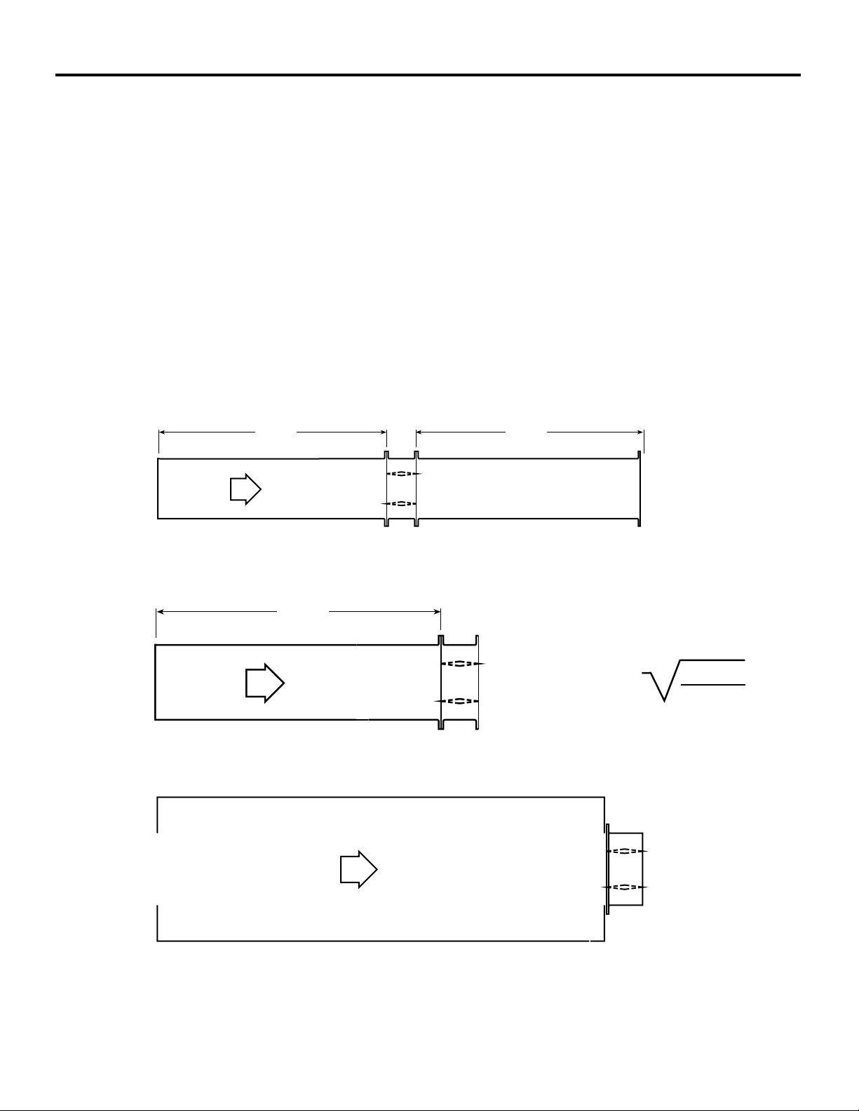
This pressure drop testing was conducted in accordance with AMCA Standard 500-D using the three configurations shown. All
data has been corrected to represent standard air at a density of .075 lb/ft3 ( 1.201 kg/m3).
Actual pressure drop found in any HVAC system is a combination of many factors. This pressure drop information along with
an analysis of other system influences should be used to estimate actual pressure losses for a damper installed in a given
HVAC system.
AMCA Test Figures
Figure 5.3 Illustrates a fully ducted damper. This configuration has the lowest pressure drop of the three test configurations
because entrance and exit losses are minimized by straight duct runs upstream and downstream of the damper.
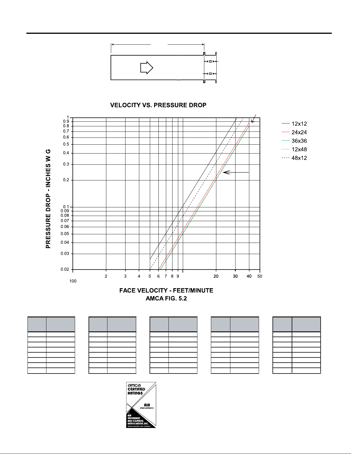
Figure 5.2 Illustrates a ducted damper exhausting air into an open area. This configuration has a lower pressure drop than
Figure 5.5 because entrance losses are minimized by a straight duct run upstream of the damper.
Figure 5.5 Illustrates a plenum mounted damper. This configuration has the highest pressure drop because of extremely high
entrance and exit losses due to the sudden changes of area in the system.
5D 6D
Figure 5.3
Figure 5.2
5D
D
4 (W) (H
3.14
)
Figure 5.5
Page 3
Velocity (fpm)
Pressure Drop
(in. wg) Velocity (fpm)
Pressure Drop
(in. wg) Velocity (fpm)
Pressure Drop
(in. wg)Velocity (fpm)
Pressure Drop
(in. wg)Velocity (fpm)
Pressure Drop
(in. wg)
500 0.02 500 0.01 500 0.01 500 0.01 500 0.02
1000 0.10 1000 0.05 1000 0.05 1000 0.05 1000 0.07
1500 0.23 1500 0.12 1500 0.111500 0.111500 0.17
2000 0.41 2000 0.21 2000 0.20 2000 0.20 2000 0.31
2500 0.64 2500 0.34 2500 0.31 2500 0.31 2500 0.49
3000 0.92 3000 0.49 3000 0.45 3000 0.45 3000 0.71
3500 1.26 3500 0.67 3500 0.62 3500 0.61 3500 0.96
4000 1.65 4000 0.87 4000 0.81 4000 0.80 4000 1.32
24 in. x 24 in.
(
610mm x 610mm)36in. x 36 in. (914mm x 914mm
)
12in. X 48 in. (305mm x 1219mm)48 in. x 12 in. (1219mm x 305mm
)
12 in. x 12 in. (305mm x 305mm
)
AMCA 5.2 Pressure Drop SSIMO-311
5D 6D
D
4 (W) (H)
3.14
5D
*
36 x 36
12 x 48
12 x 12
24 x 24
* Sizes are in inches.
48 x 12
Greenheck Fan Corporation certifies that the
R
model SSIMO-311 shown herein is licensed to bear
the AMCA Seal. The ratings shown are based on
tests and procedures performed in accordance
with AMCA Publication 511 and comply with the
requirements of the AMCA Certified Ratings Programs. The AMCA Certified Ratings Seal applies to
air performance ratings only.
Page 4

AMCA 5.3 Pressure Drop SSIMO-311
Velocity (fpm)
Pressure Drop
(in. wg) Velocity (fpm)
Pressure Drop
(in. wg) Velocity (fpm)
Pressure Drop
(in. wg)Velocity (fpm)
Pressure Drop
(in. wg)Velocity (fpm)
Pressure Drop
(in. wg)
500 0.01 500 0.01 500 0.01 500 0.01 500 0.01
1000 0.06 1000 0.02 1000 0.02 1000 0.02 1000 0.04
1500 0.13 1500 0.06 1500 0.05 1500 0.06 1500 0.10
2000 0.23 2000 0.10 2000 0.09 2000 0.10 2000 0.18
2500 0.37 2500 0.16 2500 0.14 2500 0.16 2500 0.29
3000 0.53 3000 0.23 3000 0.21 3000 0.24 3000 0.42
3500 0.73 3500 0.32 3500 0.29 3500 0.33 3500 0.57
4000 0.95 4000 0.42 4000 0.38 4000 0.43 4000 0.74
24 in. x 24 in.
(
610mm x 610mm)36in. x 36 in. (914mm x 914mm
)
12in. X 48 in. (305mm x 1219mm)48 in. x 12 in. (1219mm x 305mm
)
12 in. x 12 in. (305mm x 305mm
)
5D 6D
*
24 x 24
36 x 36
12 x 12
48 x 12
12 x 48
* Sizes are in inches.
Greenheck Fan Corporation certifies that the
model SSIMO-311 shown herein is licensed to bear
R
the AMCA Seal. The ratings shown are based on
tests and procedures performed in accordance
with AMCA Publication 511 and comply with the
requirements of the AMCA Certified Ratings Programs. The AMCA Certified Ratings Seal applies to
air performance ratings only.
Page 5

AMCA 5.5 Pressure Drop SSIMO-311
5D 6D
5D
D
4 (W) (H)
3.14
Velocity
(fpm)
Pressure Drop
(in. wg)
Velocity
(fpm)
Pressure Drop
(in. wg)
Velocity
(fpm)
Pressure Drop
(in. wg)
Velocity
(fpm)
Pressure Drop
(in. wg)
Velocity
(fpm)
Pressure Drop
(in. wg)
500 0.04 500 0.03 5000.03500 0.03 5000.03
1000 0.18 1000 0.13 1000 0.12 1000 0.12 1000 0.14
1500 0.42 1500 0.29 1500 0.27 1500 0.27 1500 0.32
2000 0.75 2000 0.52 2000 0.48 2000 0.49 2000 0.57
2500 1.17 2500 0.81 2500 0.75 2500 0.77 2500 0.89
3000 1.68 3000 1.17 3000 1.08 3000 1.11 3000 1.28
3500 2.29 3500 1.60 3500 1.48 3500 1.51 3500 1.75
4000 2.09 4000 2.14 4000 1.93 4000 1.97 4000 2.29
24 in. x 24 in. (610mm x 610mm)36in. x 36 in. (914mm x 914mm
)
12in. X 48 in. (305mm x 1219mm)48 in. x 12 in. (1219mm x 305mm
)
12 in. x 12 in. (305mm x 305mm
)
*
12 x 12
48 x 12
24 x 24
12 x 48
* Sizes are in inches.
36 x 36
R
Greenheck Fan Corporation certifies that the
model SSIMO-311 shown herein is licensed to bear
the AMCA Seal. The ratings shown are based on
tests and procedures performed in accordance
with AMCA Publication 511 and comply with the
requirements of the AMCA Certified Ratings Programs. The AMCA Certified Ratings Seal applies to
air performance ratings only.
Page 6

Application Data
53/8"
5"
Right hand drive is shown
Left hand drive available upon request
LH RH
A
Sleeve Length
Varies
6"
33/4"
11/2" max.
Damper Sleeve Dimensional Data
The drawings below and corresponding table show the position
of the SSIMO-311 damper when mounted in a factory sleeve. The
standard mounting locations provide enough space for the mounting
of actuators, controls and allow space for installation of retaining
angles and duct connections.
11/2" max.
33/4"
6"
LH RH
Right hand drive is shown
Left hand drive available upon request
S
Varies
53/8"
A
Sleeve Length
T*
5"
The standard location of a damper mounted in a
factory sleeve ("A" dimension) is shown below. The
damper can be positioned at other locations within
a range of 6 in. (152mm) to 12 in. (305mm) for the "A"
dimension.
"A" Dimension
Standard Maximum
All damper* 6
3
⁄16 in. (157mm) 12 in. (305mm)
When H is 10 in.
(254mm) or less 12 in. (305mm) 12 in. (305mm)
w/ OCI or RRL
*With the exception of dampers 10 in. (254mm) high.
Actuators and Accessories
Space Envelopes
Externally mounted actuators always require space
outside of the damper sleeve. The “S” dimension
illustrates the clearance required for various available
actuators.
Actuator
Type/Model
120 Volt AC
ML-4115 Series Honeywell 5
MS-4XXX Series Honeywell 6 in. (152mm) 3/8 in. (10mm) 6 in. (152mm)
24 Volt AC
ML-8115 Series Honeywell 5
MS-8XXX Series Honeywell 6 in. (152mm) 3/8 in. (10mm) 6 in. (152mm)
MS-8120 Series Honeywell 6 in. (152mm) 3/8 in. (10mm) 6 in. (152mm)
Pneumatic (20 or 25 psi min.)
331-4551 Powers 1 in. (25mm) 6
331-2976 Powers 2
MK2-7121 Barber-Colman 3
On dampers less than 18 in. (457mm) high, actuators
may also require clearances above and/or below
the sleeve. “B” and “T” dimensions are worst case
clearance requirements for some dampers less
than 18 in. (457 mm) high. All damper sizes under
18 in. (457mm) high do not require these worst case
clearances. If space availability above or below the
damper sleeve is limited, each damper size should be
B*
individually evaluated.
B* T*
With With
OCI or RRL
1/4 in. (133mm) 3/4 in. (19mm) 6 in. (152mm)
1/4 in. (133mm) 3/4 in. (19mm) 6 in. (152mm)
3
/8 in. (60mm) 12 1⁄8 in. (308mm) 9 1⁄4 in. (235mm)
3
⁄4 in. (95 mm) 16 1⁄2 in. (419mm) 10 in. (254mm)
OCI or RRL
1
⁄4 in. (159mm) 6 1⁄2 in. (165mm)
S
* For dampers 18 in. (457mm) or more in height these dimensions are 0 in.
Page 7

32"
32"
64"
50"
32"
96"
50"
32"
96"
Actual Size weight- lb (kg)
8 x 8 (203x203) 16 (7.3)
10 x 10 (254x254) 19 (8.6)
12 x12 (305x305) 22 (10)
18 x 18 (457x457) 33 (15)
20 x 20 (508x508) 36 (16.3)
24 x 24 (610x610) 44 (20)
30 x 30 (762x762) 57 (26)
32 x 32 (813x813) 63 (28.5)
64 x 32 (1626x813) 103 (46.7)
IMO-311/
SSIMO-311
Specifications
Damper Sizing
Information
Single Section
Dampers larger than maximum single section size are supplied as a factory assembly of two
or more sections of equal size. The following figures show maximum damper section size and
assembly configurations for multi-section dampers.
Double Section
32"
32"
32"
32"
Damper Weights- Weights are approximate. Sizing is in inches (mm).
64"
Specifications
Greenheck marine combination fire smoke damper meeting
the following specifications shall be furnished and installed
where shown on plans and/or as described in schedules.
Dampers shall be tested and rated in accordance with the
latest edition of Coast Guard Approval Type A-60 Dampers
shall consist of : a 16 gauge (1.5mm) 304 stainless steel
channel frame with 14 in. (356mm) minimum depth and 1
1/2 in. (38mm) double flanges on 20ga. (1mm) 304 stainless
sleeve; double skin airfoil type blades fabricated from two
layers of 20 ga. (1mm) 304 stainless steel; 1/2 in. (13mm) dia.
stainless steel axles turning in stainless steel bearings; and
external (out of airstream) blade-to-blade linkage.
Damper manufacturer’s printed application and performance
data including pressure, velocity and temperature limitations
shall be submitted for approval showing damper suitable for
pressures up to 4 in. wg (1 kPa) velocities to 3000 fpm
(15.2 m/s) and temperatures to 212ºF (100ºC).
Damper shall be equipped with blade and jamb seals for low
leakage performance. Blade seals shall be silicone rubber
for 400ºF (204ºC) maximum temperature. Jamb seals shall be
flexible stainless steel.
Basis of design is Greenheck SSIMO-311.
Copyright © 2011 Greenheck Fan Corporation
SSIMO-311 Rev. 5 March 2011
 Loading...