

Page 1
Document 479677
Energy Recovery Ventilator
®
Model MiniCore
Installation, Operation and Maintenance Manual
Please read and save these instructions for future reference. Read carefully before attempting to assemble, install,
operate or maintain the product described. Protect yourself and others by observing all safety information. Failure
to comply with instructions could result in personal injury and/or property damage!
Energy recovery cores are certified by the AHRI Air-to-Air Energy Recovery Ventilation Equipment Certification
Program in accordance with AHRI Standard 1060. Actual performance in packaged equipment may vary.
Certified Ratings are available in the Certified Product Directory at www.ahridirectory.org
General Safety Information
Only qualified personnel should install this system.
Personnel should have a clear understanding of these
instructions and should be aware of general safety
precautions. Improper installation can result in electric
shock, possible injury due to coming in contact with
moving parts, as well as other potential hazards. Other
considerations may be required if high winds or seismic
activity are present. If more information is needed,
contact a licensed professional engineer before moving
forward.
DANGER
Always disconnect power before working on or near
this equipment. Lock and tag the disconnect switch or
breaker to prevent accidental power up.
CAUTION
When servicing the unit, the internal components may
be hot enough to cause pain or injury. Allow time for
cooling before servicing.
CAUTION
Precaution should be taken in explosive atmospheres.
1. Follow all local electrical and safety codes, as well as
the National Electrical Code (NEC), the National Fire
Protection Agency (NFPA), where applicable. Follow
the Canadian Electrical Code (CEC) in Canada.
2. All moving parts must be free to rotate without
striking or rubbing any stationary objects.
3. Unit must be securely and adequately grounded.
4. Do not spin fan wheel faster than maximum cataloged
fan RPM. Adjustments to fan speed significantly
affects motor load. If the fan RPM is changed, the
motor current should be checked to make sure it is
not exceeding the motor nameplate amps.
5. Do not allow the power cable to kink or come in
contact with oil, grease, hot surfaces or chemicals.
Replace cord immediately if damaged.
6. Verify that the power source is compatible with the
equipment.
7. Never open access doors to the unit while it is
running.
®
MiniCore
1
Page 2

Receiving
Upon receiving the product, check to ensure all items
are accounted for by referencing the delivery receipt or
packing list. Inspect each crate or carton for shipping
damage before accepting delivery. Alert the carrier
of any damage detected. The customer will make
a notation of damage (or shortage of items) on the
delivery receipt and all copies of the bill of lading which
is countersigned by the delivering carrier. If damaged,
immediately contact your Sales Representative. Any
physical damage to the unit after acceptance is not the
responsibility of manufacturer.
Unpacking
Verify that all required parts and the correct quantity
of each item have been received. If any items are
missing, report shortages to your local representative to
arrange for obtaining missing parts. Sometimes it is not
possible that all items for the unit be shipped together
due to availability of transportation and truck space.
Confirmation of shipment(s) must be limited to only
items on the bill of lading.
Handling
Units are to be rigged and moved by the lifting brackets
provided or by the skid when a forklift is used. Location
of brackets varies by model and size. Handle in such
a manner as to keep from scratching or chipping the
coating. Damaged finish may reduce ability of unit to
resist corrosion.
Storage
Units are protected against damage during shipment. If
the unit cannot be installed and operated immediately,
precautions need to be taken to prevent deterioration of
the unit during storage. The user assumes responsibility
of the unit and accessories while in storage. The
manufacturer will not be responsible for damage during
storage. These suggestions are provided solely as a
convenience to the user.
INDOOR — The ideal environment for the storage of
units and accessories is indoors, above grade, in a
low humidity atmosphere which is sealed to prevent
the entry of blowing dust, rain, or snow. Temperatures
should be evenly maintained between 30°F (-1°C)
and 110°F (43°C) (wide temperature swings may
cause condensation and “sweating” of metal parts).
All accessories must be stored indoors in a clean, dry
atmosphere.
Remove any accumulations of dirt, water, ice, or snow
and wipe dry before moving to indoor storage. To avoid
“sweating” of metal parts allow cold parts to reach room
temperature. To dry parts and packages use a portable
electric heater to get rid of any moisture build up. Leave
coverings loose to permit air circulation and to allow for
periodic inspection.
The unit should be stored at least 3½ in. (89 mm) off the
floor on wooden blocks covered with moisture proof
paper or polyethylene sheathing. Aisles between parts
and along all walls should be provided to permit air
circulation and space for inspection.
Inspection and Maintenance during Storage
While in storage, inspect fans once per month. Keep a
record of inspection and maintenance performed.
If moisture or dirt accumulations are found on parts,
the source should be located and eliminated. At each
inspection, rotate the fan wheel by hand ten to fifteen
revolutions to distribute lubricant on motor. Every three
months, the fan motor should be energized. If paint
deterioration begins, consideration should be given to
touch-up or repainting. Fans with special coatings may
require special techniques for touch-up or repair.
Machined parts coated with rust preventive should be
restored to good condition promptly if signs of rust
occur. Immediately remove the original rust preventive
coating with petroleum solvent and clean with lint-free
cloths. Polish any remaining rust from surface with
crocus cloth or fine emery paper and oil. Do not destroy
the continuity of the surfaces. Wipe thoroughly clean
with Tectyl
hard to reach internal surfaces or for occasional use,
consider using Tectyl
or the equivalent.
REMOVING FROM STORAGE — As units are removed
from storage to be installed in their final location, they
should be protected and maintained in a similar fashion,
until the equipment goes into operation.
Prior to installing the unit and system components,
inspect the unit assembly to make sure it is in working
order.
1. Check all fasteners, set screws on the fan, wheel,
bearings, drive, motor base, and accessories for
tightness.
2. Rotate the fan wheel(s) by hand and assure no parts
are rubbing.
®
506 (Ashland Inc.) or the equivalent. For
®
511M Rust Preventive or WD-40®
2
MiniCore
®
Page 3
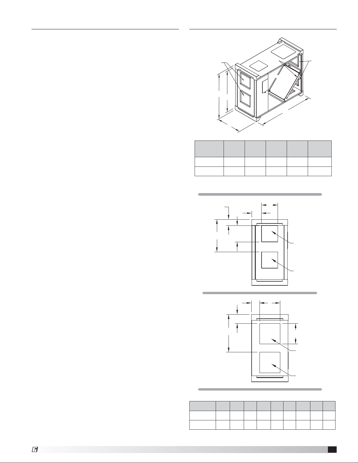
Table of Contents
Dimensional Data and Weights . . . . . . . . . . . . 3
Changing the Inlet Location . . . . . . . . . . . . . . 4
Changing the Discharge Location . . . . . . . . . . . 4
Service Clearances and Access Panel Locations . . . 4
Installation
Hang Mounting with Hanging Vibration Isolators. . 4
Base Mounting with Base Vibration Isolators. . . . 5
Duct Connections . . . . . . . . . . . . . . . . . . 6
Electrical Connections
Unit Wiring Sequence . . . . . . . . . . . . . . . . 6
Frost Control . . . . . . . . . . . . . . . . . . . . 6
Wiring Schematics . . . . . . . . . . . . . . . . . . . 7
System Start-Up
Unit Documentation Record . . . . . . . . . . . . 8
Pre-Start-Up Checklist . . . . . . . . . . . . . . . 8
Start-Up Checklist . . . . . . . . . . . . . . . . . 8
General . . . . . . . . . . . . . . . . . . . . . . . 9
Check Voltage. . . . . . . . . . . . . . . . . . . . 9
Blower Wheel Rotation . . . . . . . . . . . . . . . 9
Air Volume Check & Measurement . . . . . . . . . 9
Voltage, Amperage and Fan RPM . . . . . . . . . 9
Routine Maintenance
General . . . . . . . . . . . . . . . . . . . . . . . 9
Fasteners and Set Screws . . . . . . . . . . . . . 9
Removal of Dust and Dirt . . . . . . . . . . . . . . 9
Internal Filters . . . . . . . . . . . . . . . . . . . . 9
Energy Core . . . . . . . . . . . . . . . . . . . . 10
Optional EC Motors . . . . . . . . . . . . . . . . . 10
Troubleshooting . . . . . . . . . . . . . . . . . . . 11
Maintenance Log. . . . . . . . . . . . . . . Backcover
Our Commitment. . . . . . . . . . . . . . . Backcover
Dimensional Data and Weights
Discharge End
A
A1
B
MiniCore A A1 B C
5
10
All dimensions are in inches.
39.4 34.4 16.2 47.3 230
39.4 34.4 21.4 47.3 245
F
G
D
Filters
CoreCore
C
E
H
Discharge A
Intake End
Weight
(lbs.)
Discharge B
Discharge End
LM
J
K
Intake End
L
Intake B
Intake A
MiniCore D E F G H J K L M
9.75 9.75 3.7 19.8 3.2 5.3 22.1 12 2.1
5
10
All dimensions are in inches.
9.75 9.75 3.7 19.8 5.8 5.3 22.1 12 4.7
®
MiniCore
3
Page 4
Configurable Discharge & Intake
Locations
The MiniCore comes standard with end connections.
The option for configurable intake and discharge
connections (shaded in below drawing) are available
and can be interchanged based on application in the
field.
Outdoor Air
Exhaust Air
Discharge
Outdoor Air
Discharge
Changing the Discharge Location
Step 1 - Disconnect and lockout all power switches.
Step 2 – Remove the sheet metal block off from the
desired discharge location.
Step 3 – Cut the insulation from the desired discharge
location opening.
Step 4 – Remove the backdraft damper from its current
position and reinstall in the desired discharge location.
The hinged door should be on the discharge end of the
unit.
Step 5 – Glue the cut out insulation to the sheet metal
block off. Install where the damper had been located.
Step 6 – Using a 1/2-inch wrench, remove the four (4)
bolts from the discharge end of the unit that holds the
blowers.
Step 7 – Remove the four (4) plastic plugs from the
desired discharge location and reinstall the plastic
plugs in the holes where the bolts were removed from in
Step6.
Step 8 – Position the blowers to line up with the
desired discharge location. The motor needs to be on
the discharge end of the blower and unit. If the motor
is positioned on the return side of the blower/unit, the
motor/blower will interfere with the energy recovery
core. The blower adjacent to the control center needs to
be rotated 90°. The blower not adjacent to the control
center needs to be flipped and rotated such that the
motor is now opposite the control center side of the
unit. It may be necessary to unwire the motors.
Step 9 – Bolt the blowers in their desired locations.
Securely reconnect and fasten all wires.
Intake
Exhaust Air
Intake
Changing the Inlet Location
Step 1
- Remove the metal cover for optional inlet
location by unfastening the four (4) sheet metal screws
holding it in place.
Step 2 - Hand bend flanges out to form a duct collar in
the newly uncovered intake opening.
Step 3 - Cut insulation.
Step 4 - Hand bend flanges in on original intake and
replace metal cover removed in Step 1.
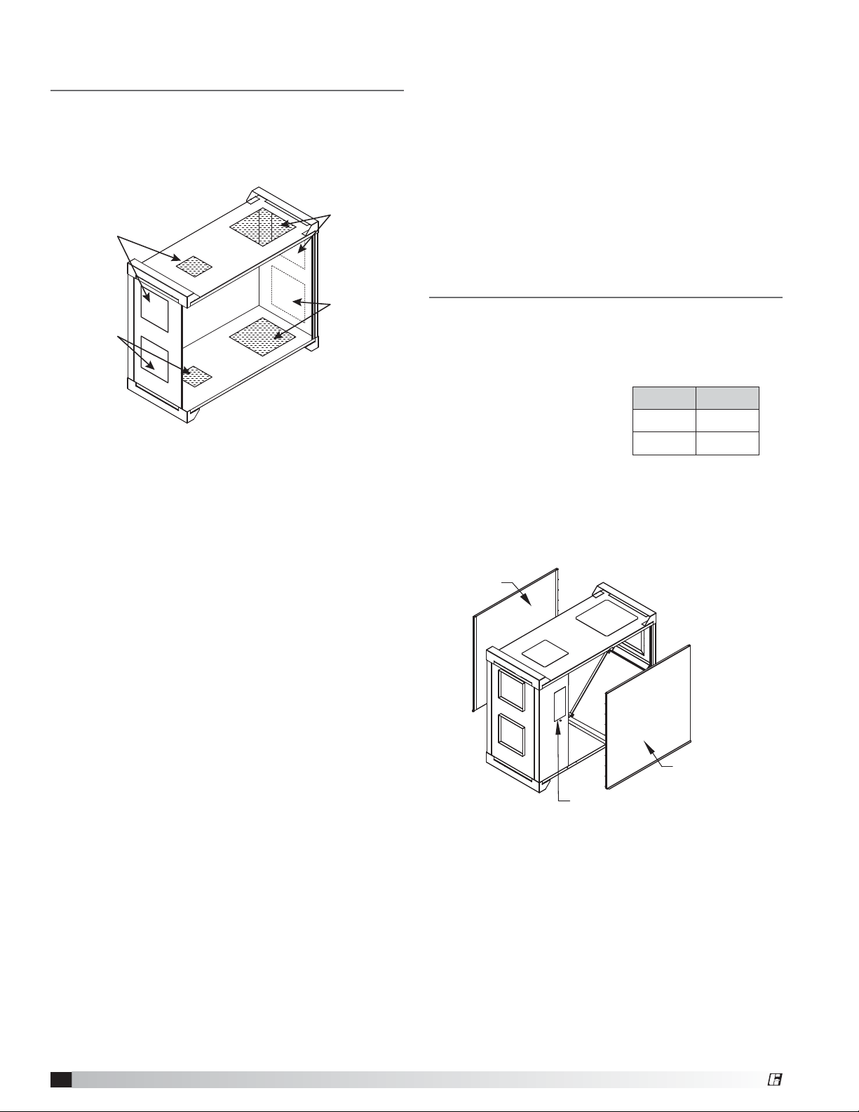
Service Clearances and Access
Panel Locations
Recommended Service Clearances
The MiniCore requires minimum clearances to perform
routine maintenance, such as filter replacement, energy
core cleaning and fan inspection. Fan and motor
assemblies, energy recovery
core and filter sections are
provided with a service
door or panel for proper
component access.
Access Panel Locations
• Outdoor and exhaust fans and motor
• Electrical connection
• Energy core and internal filters
Energy Core and Filter
Access Panel
Electrical Input
MiniCore Inches
5
10
Energy Core and Filter
Access Panel
30
30
4
MiniCore
®
Page 5

Installation
The system design and installation should follow
accepted industry practices, such as described in the
ASHRAE Handbook and SMACNA.
Minimum service clearance should be provided on
the side of the unit for routine service and component
removal should it become necessary.
Before beginning installation see page 4 for appropriate
service clearances
Hang Mounting
with Hanging Vibration Isolators
• The hanging isolator kit includes four (4) isolators and
required hardware.
• Locate the support rods as shown in the drawing.
• Assemble each isolator as shown below.
B
A
C
Base Mounting
with Base Vibration Isolation
• The base isolators kit includes four (4) isolators,
four (4) brackets and required hardware.
• Assemble and mount the isolators as shown in the
figures below.
Factory-mounted
bracket
Hanger bracket,
factory-mounted
Hanging Vibration Isolator Assembly
Nut
MiniCore A B C
44.8 14 39.4
5
10
All dimensions are in inches.
44.8 19.2 39.4
1/2-inch threaded rod,
provided by others
Lock Washer
Flat Washer
Isolator
Flat Washer
Lock Washer
Nut
3/8-inch bolt
Lock washer
Flat washer
Isolator
Base Vibration Isolator Assembly
Assembled and Mounted Isolator Detail
®
MiniCore
5
Page 6

Duct Connections
Examples of good and poor fan-to-duct connections are
shown below. Airflow out of the fan should be directed
straight or curve the same direction as the fan wheel
rotates. Poor duct installation will result in low airflow,
loud noise and excessive vibrations.
n
o
i
t
a
t
o
R
POOR
n
o
i
t
a
t
o
R
Length of Straight Duct
GOOD
Recommended Discharge Duct Size and Length
MiniCore
5
10
All dimensions are in inches.
ERV
Blower Size
10 9.75 43
10 9.75 43
Duct
Size
Straight Duct
Length
Electrical Connections
Before connecting power to the unit, read and
understand the following instructions and wiring
diagrams. Complete wiring diagrams are attached inside
the energy core and filter access panel of the unit.
All wiring should be done in accordance with the
National Electrical Code ANSI/NFPA 70 latest edition
and any local codes that may apply. In Canada, wiring
should be done in accordance with the Canadian
Electrical Code. The equipment must be properly
grounded.
Electrical connections are located below the energy
core and filter access panel . A knock out location is
provided with the unit.
CAUTION
If any of the original wire must be replaced, the
replacement wire must have a temperature rating of at
least 105ºC.
DANGER
High voltage electrical input is required for this
equipment. This work should be performed by a
qualified electrician.
Unit Wiring Sequence
1. The unit’s nameplate contains the voltage and total
amperage required. The wire supplying power to the
unit should be sized accordingly.
2. The main power line should be connected to the
appropriate terminal blocks.
Power may be routed to the MiniCore through the
knock out under the control center.
3. Refer to the wiring diagrams in this manual or in the
unit for controlling the MiniCore.
Timed Exhaust Frost Control
Extremely cold outdoor air temperatures can cause
moisture condensation and frosting on the energy
recovery core. Timed exhaust frost control is an optional
feature that will prevent/control core frosting.
Timed exhaust frost control includes a timer as well as
a thermodisc that is field-installed in the outdoor air
duct. When timed exhaust frost control is initiated, the
timer will turn the supply blower off. Time exhaust using
default timer setting will shut down the supply fan for
5 minutes every 30 minutes to allow exhaust to defrost
energy core.
Use the Frost Control Test Procedure outlined below for
troubleshooting.
Frost Control Test Procedure
1. Remove power from unit.
2. Jumper the temperature indicating thermodisc in
the unit control center. Thermodisc has a pre-set
temperature of 5ºF.
3. Set the frost control timer scale for T1 and T2 to 1m.
Set the timer settings for T1 and T2 to 10.
4. Add power to the unit. Blower should cycle on for one
minute, then turn off for one minute.
5. Remove power from unit
and remove jumpers that
were placed. Reset timer
settings.
• T1 timer setting set to
5 and timer scale set
to 10m for 5 minutes
of wheel off time.
• T2 timer setting set to
5 and timer scale set
to 1h for 30 minutes of
wheel on time.
Timer
Scale
Timer
Settings
Timer
Scale
T1
T2
6
MiniCore
®
Page 7

Wiring Schematics
Timed Exhaust Frost Control
COM
NO
TR
R
TH
A1
YELLOW
B1
T1
A2
REMOTE PANEL
115/208/230V PRIMARY
24V SECONDARY
FIELD MOUNT
IN OUTDOOR
AIR DUCT
VIOLET
RED
ORANGE
BLACK
15
T1
GROUND
115
208
230
FIELD TO CONNECT
TO TERMINAL DESIGNATED
WITH UNIT LINE VOLTAGE
CONNECT TERMINAL 15
FROM COMPONENT "T1"
WITH LINE VOLTAGE
L2
PURPLE
T A OR B
16
INTERNAL JUNCTION BOX
L1
L2
L1
MAIN UNIT
Potentiometer Control
(VERIFY MAIN UNIT POWER ON UNIT NAMEPLATE)
MAIN UNIT POWER -110/50/1-115/60/1
L2/NEUTRAL
L2 L1
GROUND
L1
A
B
BLACK
WHITE
BLACK
WHITE
Solid State Speed Motor Control
(VERIFY MAIN UNIT POWER ON UNIT NAMEPLATE)
MAIN UNIT POWER - 110/50/1-115/60/1
L2/NEUTRAL
L2
BLOWER MOTOR A
MA
BLOWER MOTOR B
MB
Legend
MA Blower Motor A
MB Blower Motor B
T1 Frost Control Timer
Typical Settings: t1 (OFF) = 5 min.
TH Thermostat; non-adjustable 5° setting.
Required to be mounted in outdoor air duct.
TR Transformer
t2 (ON) = 30 min.
L1
L1
A
B
GROUND
BLOWER A
SPEED CONTROLLER
ON OFF
BLOWER B
SPEED CONTROLLER
ON OFF
A2
B2
BLACK
BLACK
BLOWER MOTOR A
MA
BLOWER MOTOR B
MB
®
MiniCore
7
Page 8

System Start-Up
DANGER
Electric shock hazard. Can cause injury or death.
Before attempting to perform any service or
maintenance, turn the electrical power to unit to OFF
at disconnect switch(es). Unit may have multiple
power supplies.
CAUTION
Use caution when removing access panels or other
unit components, especially while standing on a
ladder or other potentially unsteady base. Access
panels and unit components can be heavy and
serious injury may occur.
CAUTION
Do not operate without the filters installed. They
prevent the entry of foreign objects such as leaves,
birds, etc.
CAUTION
Do not run unit during construction phase. Damage to
internal components may result and void warranty.
WARNING
Do not jumper any safety devices when operating the
unit. This may damage components within or cause
serious injury or death.
SPECIAL TOOLS
• Voltmeter
• Incline manometer or equivalent
• Tachometer
• Amperage meter
Every installation requires a comprehensive start-up
to ensure proper operation of the unit. As part of that
process, the following checklist must be completed and
information recorded. Starting up the unit in accordance
with this checklist will not only ensure proper operation,
but will also provide valuable information to personnel
performing future maintenance. Should an issue arise
which requires factory assistance, this completed
document will allow unit experts to provide quicker
resolve. Qualified personnel should perform start-up to
ensure safe and proper practices are followed.
Unit Documentation Record
Unit Model No. __________________________________
Unit Serial No. ____________________________________
Start-Up Date ____________________________________
Start-Up Personnel Name _________________________
Start-Up Company ________________________________
Phone Number ___________________________________
Pre-Start-Up Checklist
Disconnect and lock-out all power switches.
Remove any foreign objects that are located in the
energy recovery unit.
Check all fasteners, set-screws, and locking collars
on the fans, bearings, drives, motor bases and
accessories for tightness.
Filters can load up with dirt during building
construction. Replace any dirty pleated filters.
Verify that non-motorized dampers open and close
properly.
Check the tightness of all factory wiring
connections.
Verify control wire gauge.
Start-Up Checklist
Line Voltage. Check at unit disconnect.
L1-L2 Volts
Motor Amp Draw
Supply Motor Amps L1 Amps L2 Amps
Exhaust Motor Amps L1 Amps L2 Amps
Fan RPM
Supply Fan RPM
Exhaust Fan RPM
Correct fan rotation direction?
Supply Fan Yes / No
Exhaust Fan Yes / No
MiniCore
8
®
Page 9

General
Airflow
Check all fasteners and set screws for tightness. This is
especially important for bearings and fan wheels Also,
if dampers are not motorized, check that they open and
close without binding.
Check Voltage
Before starting the unit compare the supplied voltage
with the unit’s nameplate voltage and the motor voltage.
Check Blower Wheel Rotation
First, hand rotate the
blower to ensure that
the wheel is not rubbing
against the scroll. If the
blower is rotating in the
n
o
i
t
a
t
o
R
wrong direction, the unit
will move some air but not
perform properly.
Forward Curved
To check the rotation, open the blower access panel,
and run the blower momentarily to determine the
rotation.
Air Volume Check and Measurement
Along with the building balance, the unit’s airflow (cfm)
should be measured and compared with its rated air
volume. The MiniCore is direct drive, therefore balancing
dampers or speed controls are required for airflow
balancing. Air volume measurement must be conducted
with access doors on the unit.
The most accurate way to measure the air volume is
by using the pitot traverse method in the ductwork
away from the blower. Other methods can be used, but
should be proven and accurate.
To adjust the air volume, change the fan rpm or the
system static pressure.
With all access panels on the unit, compare measured
amps to the motor nameplate full load amps and correct
if overamping.
Measure Motor Voltage, Amperage and
FanRPM
All access doors must be installed, run the
measurement leads through the provided electrical
access hole in the bottom access panel of the MiniCore.
Measure and record the input voltage and motor
amperage(s).
With all access panels on the unit, compare measured
amps to the motor nameplate full load amps and correct
if overamping.
Routine Maintenance
WARNING
Disconnect all electrical power to the MiniCore prior
to inspection or servicing. Failure to comply with this
safety precaution could result in serious injury or
death.
Improper installation, adjustment, alteration, service
or maintenance can cause property damage, injury
or death. Read the installation, operating, and
maintenance instructions thoroughly before installing
or servicing this equipment.
After the MiniCore has been put into operation, an
annual inspection and maintenance program should be
set-up to preserve reliability and performance.
The MiniCore energy recovery ventilator requires
very little maintenance. However, small problems
left unchecked, over time, could lead to loss of
performance or early motor failure. We recommend that
the unit be inspected once a year.
The motor should be checked for lubrication at this
time. Lubricate only those motors which have an oil hole
provided. A few drops of all-purpose oil (SAE 20) will be
sufficient.
Fasteners and Set Screws
Any fan vibration has a tendency to loosen mechanical
fasteners. A periodic inspection should include
checking all fasteners and set screws for tightness.
Particular attention should be paid to set screws
attaching the fan wheel to the shaft. Loose bearing set
screws will lead to premature failure of the fan shaft.
Removal of Dust and Dirt
The fan motor and wheel(s) should be checked for
dust and dirt accumulation. Dirt buildup clogs cooling
openings on the motor housing and causes motor
overheating. Dirt buildup can contaminate bearing
lubricant and collect on fan wheel blades causing loss
of performance or premature failure. Cleaning can be
accomplished by brushing off any dust that may have
accumulated. Under no circumstances should motors or
bearings be sprayed with steam or water. Even filtered
units can accumulate build up and should be checked
when cleaning filters.
Maintenance to these components is achieved through
the provided access panels.
Internal Filter Maintenance
Opening the access panel provides access to the two
inches deep, pleated
30% efficient filters.
These filters should
be checked regularly
and cleaned or
replaced as needed.
MiniCore
5
10
Internal
Filter Size
15 x 20 2
20 x 20 2
Quantity
®
MiniCore
9
Page 10

Energy Core
Annual inspection of the energy recovery core is
recommended. MiniCore units ventilating smoking
lounges and other non-clean air spaces should have
energy recovery core inspections more often based
upon needs.
Accessing the energy recovery core - Disconnect
the power to the MiniCore. Remove access panel.
Removing the energy recovery core - Once the
energy core access doors are removed, the core can be
pulled from the housing. To replace the core, reverse the
procedure.
Recommended cleaning procedure - First, remove
the energy recovery core by following the instructions
on this page.
Once the core is removed, gently vacuum the surfaces
of the core to remove the dirt and debris that has
accumulated.
WARNING
Do not wash, soak in water or use detergents and
cleaners on the core. This will result in a damaged
core.
Frequency of cleaning - A regular cleaning cycle
must be established for the energy recovery core in
order to maintain optimum sensible and latent energy
transfer. In reasonably clean environments such as
schools, offices or retail stores, the energy recovery core
should be inspected annually and cleaned as needed.
Failure to follow a regular cleaning cycle for the energy
recovery core can result in significant energy transfer
performance losses.
Optional EC Motor
Features
Soft start – All motors
feature soft-start
technology which
eliminates inrush
current at start-up.
The motors will reliably
start at any speed
setting.
Overload protection – If the motor becomes
overloaded, it will automatically reduce its speed until it
is no longer overloaded. This means that the motor will
never operate in the “service factor” which is possible
with many AC motors.
Locked rotor protection – If the motor ever encounters
a locked-rotor scenario, the motor will automatically
shut itself down. It will try to restart up to 3 times, and if
after the 3rd time the motor will still not rotate, the motor
will not attempt to start again until power is cycled.
Thermal protection – The motors have a one-shot
fuse thermal protector. This is meant to protect the
motor from a severe temperature rise. With the motor
controller’s ability to software limit the speed, the fuse
is used as a last resort to prevent a fire.
RPM measurement – The motors have a small shaft
extension on the end of the motor to measure motor
RPM with either a contact or optical tachometer.
Operation and Wiring - Potentiometer Dial
These motors feature a potentiometer dial on the motor
for speed adjustment. A small screwdriver can be used
to make the speed adjustment. To increase the speed,
rotate the dial clockwise. To decrease the speed, rotate
the dial counterclockwise.
10
MiniCore
®
Page 11

Troubleshooting
Symptom Possible Cause Corrective Action
Unit is NOT
Electrical
Check fuses/circuit breakers, replace if needed. Check for On/
Off switches. Check for correct supply voltage.
operating
Motor Check motor horsepower is correct and not tripping overloads.
Adjust wheel and/or inlet cone. Tighten wheel hub or bearing
collars on shaft.
Replace defective bearing(s). Lubricate bearings. Tighten collars
and fasteners.
Excessive noise
Fan wheel rubbing on inlet
Bearings
Wheel out of balance Clean, replace or rebalance.
Fan speed too low Increase fan speed.
Low airflow (cfm)
Dirty filters or energy core Replace filters and/or follow the cleaning procedures.
High static pressure
Incorrect fan-to-duct connections. Make sure dampers open
appropriately. Increase fan speed
Fan speed too high Decrease fan speed.
High airflow (cfm)
Low static pressure
Make sure grilles, filters and access doors are installed.
Decrease fan speed.
Always provide the unit model and serial number when requesting parts or service information. Always check
motor amps and compare to nameplate rating.
®
MiniCore
11
Page 12

Maintenance Log
Date ___________________Time _____________ AM/PM
Notes: ___________________________________________
_________________________________________________
_________________________________________________
_________________________________________________
_________________________________________________
Date ___________________Time _____________ AM/PM
Notes: ___________________________________________
_________________________________________________
_________________________________________________
_________________________________________________
_________________________________________________
Date ___________________Time _____________ AM/PM
Notes: ___________________________________________
_________________________________________________
_________________________________________________
_________________________________________________
_________________________________________________
Date ___________________Time _____________ AM/PM
Notes: ___________________________________________
_________________________________________________
_________________________________________________
_________________________________________________
_________________________________________________
Date ___________________Time _____________ AM/PM
Notes: ___________________________________________
_________________________________________________
_________________________________________________
_________________________________________________
_________________________________________________
Date ___________________Time _____________ AM/PM
Notes: ___________________________________________
_________________________________________________
_________________________________________________
_________________________________________________
_________________________________________________
Date ___________________Time _____________ AM/PM
Notes: ___________________________________________
_________________________________________________
_________________________________________________
_________________________________________________
_________________________________________________
Date ___________________Time _____________ AM/PM
Notes: ___________________________________________
_________________________________________________
_________________________________________________
_________________________________________________
_________________________________________________
Our Commitment
As a result of our commitment to continuous improvement, Greenheck reserves the right to change specifications
without notice.
Specific Greenheck product warranties can be located on greenheck.com within the product area tabs and in
the Library under Warranties.
Greenheck’s Energy Recovery Ventilator, Model MiniCore
catalog, provides additional information describing the
equipment, fan performance, available accessories, and
specification data.
AMCA Publication 410-96, Safety Practices for Users and
Installers of Industrial and Commercial Fans, provides
additional safety information. This publication can be
obtained from AMCA International, Inc. at www.amca.org.
®
Phone: 715.359.6171 • Fax: 715.355.2399 • Parts: 800.355.5354 • E-mail: gfcinfo@greenheck.com • Website: www.greenheck.com
479677 • MiniCore, Rev. 1, December 2014 Copyright 2014 © Greenheck Fan Corporation
12
 Loading...