

Page 1
Document 475595
Microprocessor Controller for
®
Tempered Air Products
Reference Guide for the Microprocessor Controller
Please read and save these instructions. Read carefully before attempting to operate or maintain the product
described. Protect yourself and others by observing all safety practices. Failure to comply with instructions
could result in personal injury and/or property damage! Retain instructions for future reference.
TAP v2.10
Version Date: 4/1/14
Introduction
Program Features
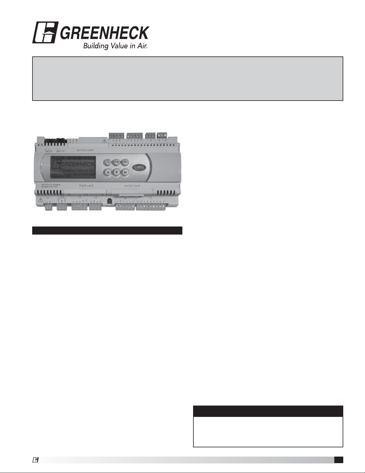
The microprocessor controller offers improved control
through easy monitoring and adjustment of unit
parameters by way of a lighted graphical display and a
push-button keypad.
Pre-Programmed Operating Sequences
The controller has been pre-programmed to offer
multiple control sequences to provide tempered
air. Factory default settings allow for easy setup
and commissioning. The sequence parameters are
fully adjustable. Refer to the Sequence of Operation
beginning on page 2 for details.
BMS Communication
With the addition of an optional BMS Communication
card, the user can remotely adjust set points, view
unit status points and alarms. The microprocessor
controller is capable of communicating over several
protocols:
• BACnet® MSTP • LonWork®
• BACnet® IP/Ethernet • Modbus
See Points List on pages 36 and 37 for a complete list
of BMS points.
Internal Time Clock
The controller has an internal programmable time
clock, allowing the user to add up to seven different
occupancy schedules. The user may also add Holidays
for additional energy savings. The time clock option
also has morning warm-up capability for optional
comfort at the time of occupancy.
Alarm Management
The microprocessor controller will monitor the unit
conditions for alarm conditions. Upon detecting an
alarm, the controller will record the alarm description,
time, date, available temperatures, and unit status for
user review. A digital output is reserved for remote
alarm indication. Alarms are also communicated via
BMS (if equipped).
Occupancy Modes
The microprocessor controller offers three modes of
determining occupancy: a dry contact, the internal time
clock or the BMS. If in the Unoccupied mode the unit
will either be shut down, or will cycle on to maintain
adjustable unoccupied room temperature and humidity
set points.
Remote Display Panel (Optional)
A touchpad display panel allows for remote monitoring
and adjustment of parameters, allowing ease of control
access without going outdoors.
WARNING
Electrical shock hazard. Can cause personal injury
or equipment damage. Service must be performed
only by personnel that are knowledgeable in the
operation of the equipment being controlled.
®
DDC Controller for Tempered Air Products
1
Page 2

Table of Contents Sequence of Operation
Sequence of Operation . . . . . . . . . . . . . . . 2
General Operation. . . . . . . . . . . . . . . . 2-3
Set Point Control. . . . . . . . . . . . . . . . . . 3
Heating. . . . . . . . . . . . . . . . . . . . . . . 3
Cooling. . . . . . . . . . . . . . . . . . . . . . . 3
Economizer . . . . . . . . . . . . . . . . . . . . 4
Dehumidification. . . . . . . . . . . . . . . . . . 4
Reheat . . . . . . . . . . . . . . . . . . . . . . . 4
Supply Fan VFD . . . . . . . . . . . . . . . . . . 4
Exhaust Fan VFD . . . . . . . . . . . . . . . . . 5
Outdoor Air and Recirculated (Recirc) Air . . . . . 5
Energy Recovery Wheel Sequence . . . . . . . . 5
Alarms . . . . . . . . . . . . . . . . . . . . . . . 5
Controller Overview . . . . . . . . . . . . . . . . 6-7
Display Use . . . . . . . . . . . . . . . . . . . . . 8
Example of Parameter Adjustment . . . . . . . . . 8
Example of Alarms. . . . . . . . . . . . . . . . . . 9
Menu Overview . . . . . . . . . . . . . . . . . 10-11
Main Menu Overview . . . . . . . . . . . . . . 12-14
Menus
A.
On/Off Unit . . . . . . . . . . . . . . . . . 14
B.
Setpoint . . . . . . . . . . . . . . . . 15-21
C.
Clock/Scheduler . . . . . . . . . . . . . .22
D.
Input/Output . . . . . . . . . . . . . . . .22
E.
Data Logger . . . . . . . . . . . . . . . . 22
F.
Board Switch. . . . . . . . . . . . . . . .23
G.
Service
a. Information. . . . . . . . . . . . . . . . .23
b. Overrides . . . . . . . . . . . . . . . 23-25
c. BMS Config . . . . . . . . . . . . . . 26-27
d. Service Settings
a. Working hour set . . . . . . . . . . . . 27
b. Probe adjustment. . . . . . . . . . . .27
c. Password/Defaults . . . . . . . . . . . 27
H.
Manufacturer
a. Configuration . . . . . . . . . . . . . . . 28
b. I/O Configuration . . . . . . . . . . . . . 28
c. Factory Settings . . . . . . . . . . . . 29-34
d. Initialization . . . . . . . . . . . . . . . . 35
Remote Display . . . . . . . . . . . . . . . . . . . 35
Points List
LonWorks® . . . . . . . . . . . . . . . . . . . .36
ModBus/BACnet®. . . . . . . . . . . . . . . . .37
Expansion I/O (pCOe) . . . . . . . . . . . . . . . .38
Troubleshooting . . . . . . . . . . . . . . . . . . . 39
NTC Temperature Sensor Chart. . . . . . . . . . .39
BACnet® MSTP Quick Start. . . . . . . . . . . . .40
BACnet® IP/Eth Quick Start. . . . . . . . . . . . .41
Economizer Commissioning Tool . . . . . . . . . .42
Maintenance Log . . . . . . . . . . . . . . . . . . 43
Our Commitment. . . . . . . . . . . . . . Backcover
The microprocessor controller can be configured for air
handler, energy recovery, dedicated outdoor air system
and make-up air applications. Each application utilizes
similar technologies for heating and cooling: chilled
water, hot water, indirect gas, electric heat, packaged
DX cooling, and packaged DX cooling with digital
scrolls. All set points, lockouts and delays are user
adjustable via the keypad display.
General Operation
UNIT START COMMAND: The microprocessor
controller requires a digital input to enable operation.
The unit can then be commanded on or off by this
digital input, the BMS or internal time clock.
• Initial delay
• Factory mounted and wired dampers are powered, if
equipped. (Outdoor air, exhaust air, and recirculation
air dampers).
• Exhaust fan and energy recovery wheel start after a
10 second delay, if equipped.
• Supply fan starts 15 seconds after the exhaust fan.
• Tempering operation begins (see modes below).
UNIT STOP COMMAND (OR DE-ENERGIZED):
• Supply fan, exhaust fan, tempering, and wheel are
de-energized.
• Outdoor air and Exhaust air dampers are closed after
a 10 second delay. Recirculation air dampers spring
open.
OCCUPIED/UNOCCUPIED MODES: The
microprocessor controller offers three modes of
determining occupancy: a dry contact, the internal time
clock or the BMS. When in the unoccupied mode, the
unit can be configured to shut down, or cycle on to
maintain the unoccupied room set points. The unit can
be temporarily overridden to the occupied mode via a
digital input or the keypad display.
The internal time clock can be configured with morning
warm-up to bring the space to the occupied set point
prior to occupancy.
• Occupied Mode:
- Exhaust fan on, if equipped
- Supply fan on
- Heating (refer to Heating section)
- Cooling (refer to Cooling section)
- Energy Recovery Wheel control (refer to
Energy Recover Wheel section), if equipped.
- Damper control (refer to Outdoor Air and
Recirculated Air section), if equipped.
• Unoccupied Mode (Unit Off): Unit remains off when
in unoccupied mode.
• Unoccupied Mode (Cycle on Room): Optional
unoccupied mode when there is an unoccupied
recirculation damper and room temperature and/
or humidity sensor(s) connected to the controller.
The unit will cycle on to maintain unoccupied room
set points if there is a call for unoccupied heating,
cooling or dehumidification.
DDC Controller for Tempered Air Products
2
®
Page 3

Sequence of Operation
- Exhaust fan off, if equipped.
- Supply fan off.
- Recirculation air damper open.
- OA damper closed.
- Tempering operations begin (see modes below)
Set Point Control (Occupied)
Supply air temperature set point can be configured
as constant, or can be reset by either outside air
temperature, or room temperature set point. If equipped
with BMS communications, the user can also directly
command the supply temperature set point, or room
temperature set point (if equipped with a room temp
sensor).
• Outdoor Air Temperature Reset Function: The
controller will default to supply temperature reset
based on outdoor air temperature. The controller will
monitor the OA temperature and reset the supply
temperature set point based upon the outdoor air
reset function.
• Room Temperature Reset (optional): With a
room temperature sensor, the controller will adjust
the supply air temperature set point between the
minimum (55°F) and maximum (90°F), to satisfy the
desired room temperature.
Set Point Control (Unoccupied)
When equipped with an unoccupied recirculation
damper and optional room temperature and/or
humidity sensors, the unit will cycle on to maintain the
unoccupied room set points.
• Unoccupied Heating: If equipped with heating,
the unit is enabled when the room temperature is
less than the unoccupied heating set point minus
differential (65°F-5°F). The supply air temperature
set point will be set to the supply maximum reset
limit (90°F). The unit cycles off when the room
temperature reaches the unoccupied heating set
point.
• Unoccupied Cooling: If equipped with cooling,
the unit is enabled when the room temperature is
greater than the unoccupied cooling set point plus
differential (80°F+5°F). The supply air temperature
set point will be set to the supply minimum reset
limit (55°F). The unit cycles off when the room
temperature reaches the unoccupied cooling set
point.
• Unoccupied Dehumidification: If equipped with
cooling, the unit is enabled when the room relative
humidity exceeds the unoccupied room relative
humidity set point plus differential (50%+5%), or
when dehumidistat contact indicates excessive
humidity. The supply air temperature set point will be
set to the equivalent occupied supply set point.
• Morning Warm-Up: The unit uses an algorithm
involving space temperature and the heating /cooling
rate of the previous day to determine the time
required to efficiently temper the space to occupied
set point prior to occupancy.
Heating
The heating is controlled to maintain the supply
temperature set point. The heating will be locked out
when the outside air temperature is above the heating
lockout (70°F).
• Indirect Gas Furnace: Microprocessor controller
will modulate the indirect gas furnace to maintain the
supply temperature set point.
• Hot Water Coil: Microprocessor controller will
modulate a hot water valve (provided by others)
to maintain the supply temperature set point. Coil
freeze protection must be provided by others in
the field!
• Electric Heater: Microprocessor controller will
modulate an electric heater to maintain the supply
temperature set point.
• Heat Pump: Microprocessor controller will stage
compressor(s) to maintain the supply air set point.
This signal will come wired to the factory provided
heat pump module. All external water valves and
valve controls are provided, wired and mounted
by others in the field, including freeze protection.
Cooling
The cooling is controlled to maintain the supply
temperature set point. The mechanical cooling will be
locked out when the outside air temperature is below
the cooling lockout (55°F).
• Chilled Water: Microprocessor controller will
modulate a chilled water valve (provided by others) to
maintain supply air set point. Coil Freeze protection
must be provided by others in the field!
• Packaged DX Cooling (Standard Scroll):
Microprocessor controller will control stages of
cooling to maintain the supply air set point.
• Packaged DX Cooling (Digital Scroll):
Microprocessor controller will modulate the digital
scroll to maintain the supply air temperature set
point.
• Heat Pump: Microprocessor controller will power
the reversing valve within the heat pump module
to direct the refrigerant flow for airside cooling.
The cooling is controlled to maintain the supply
temperature set point. All external water valves and
valve controls are provided, wired and mounted
by others in the field, including freeze protection.
®
DDC Controller for Tempered Air Products
3
Page 4

Economizer
If the application requires cooling, and the outdoor
air conditions are suitable for free cooling, the
controller may enter the economizer state. If the unit is
economizing and the discharge temperature set point is
not being met, the controller may bring on mechanical
cooling. If equipped with a modulating outdoor air and
recirculated air damper, the dampers will modulate
between the minimum OA and maximum positions to
maintain the supply temperature set point. If equipped
with an energy wheel, see Energy Recovery Wheel
Sequence.
• Temperature: The economizer will be locked out
when:
- The outside air is less than the economizer low
lockout (40°F).
- The outside air is greater than the economizer
high lockout (65°F).
- The unit is operating in dehumidification mode.
- There is a call for heating.
• Temperature/Dew Point: The economizer will be
locked out when:
- The outside air is less than the economizer low
lockout (40°F dry-bulb).
- The outside air is greater than the economizer
high lockout (75°F dry-bulb).
- The outside air is greater than the economizer
high dew point lockout (55°F dew point)
- The unit is operating in dehumidification mode.
- There is a call for heating.
Dehumidification
The cooling is controlled to maintain the cold coil set
point. The dehumidification sequence will be locked out
when the OA is less than the dehumidification lockout
(10°F) above the cold coil set point. If equipped with
BMS communications, the user can also directly set the
cold coil leaving air set point.
• Optional Room Dehumidistat: The room
dehumidistat is a field mounted sensor that monitors
the relative humidity (RH) of the room. If the RH
exceeds set point, the dehumidistat will reset the
cold coil set point to the minimum (50°F). Once the
room dehumidistat is satisfied, the cold coil set point
will return to the maximum (55°F).
• Optional Room Relative Humidity Sensor: The
controller will adjust the cold coil leaving air
temperature set point between the minimum (50°F)
and maximum (55°F) set points, to satisfy the desired
room relative humidity set point.
Reheat
While the unit is in dehumidification mode, the supply
air can be reheated via Primary Heating Source, On/Off
Hot Gas Reheat or Modulating Hot Gas Reheat.
• Primary Heating Source: The main heating source
is enabled to reheat the air to meet the supply
temperature set point. (Except heat pump). The
DDC Controller for Tempered Air Products
4
primary heat source may also be configured to act as
secondary reheat.
• Modulating Hot Gas Reheat (bypass damper): The
microprocessor controller will open the On/Off hot
gas reheat valve, and modulate the Hot Gas Reheat
bypass damper to maintain the supply temperature
set point.
• Modulating Hot Gas Reheat (valve): The
microprocessor controller will modulate the hot gas
reheat valve to maintain the supply temperature set
point.
• On/Off Hot Gas Reheat: The microprocessor
controller will open the On/Off hot gas reheat valve to
maintain the supply temperature set point.
Supply Fan VFD Sequence
If the factory has installed a VFD and wired it to the
controller, it is intended to operate at a constant speed
during operation. This speed needs to be set during
test and balance of the unit. If equipped with BMS
communications, the user can also directly command
the supply fan speed.
• Optional Room CO2 Sensor: The controller will
modulate the supply fan based upon a comparison
of the CO2 set point to the actual CO2 levels
reported from the sensor. Mechanical high static
protection cutoffs must be installed by others
to protect the system and equipment from
over-pressurization.
• Optional Duct Static Pressure Sensor: The
controller will modulate the supply fan based upon a
comparison of the duct static pressure set point to
the actual duct static pressure level reported from
the sensor. Mechanical high static protection
cutoffs must be installed by others to protect
the system and equipment from overpressurization. The manufacturer does not
assume responsibility for this.
• Optional Building Static Pressure Sensor: The
controller will modulate the supply fan based upon a
comparison of the building static pressure set point
to the actual building static pressure level reported
from the sensor.
• Optional Single Zone VAV (SZ): The controller will
control the supply air temperature and supply fan
speed to maintain the room temperature set point.
This sequence requires a room temperature sensor.
Heating - When the room requires heating, the
controller will reset the supply air temperature set
point up to the maximum (90°F) while increasing the
supply fan speed up to its maximum heating speed.
Cooling - When the room requires cooling, the
controller will first reset the supply air temperature
set point down to the minimum (55°F) while the
supply fan remains at the minimum cooling speed.
After a time delay, the supply fan speed will increase
up to its maximum cooling speed to maintain the
room temperature set point.
®
Page 5

Exhaust Fan VFD Sequence
If the factory has installed a VFD and wired it to the
controller, it is intended to operate at a constant speed
during operation. This speed needs to be set during
test and balance of the unit. If equipped with BMS
communications, the user can also directly command
the exhaust fan speed.
• Optional Building Static Pressure Sensor: The
controller will modulate the exhaust fan based upon
a comparison of the building static pressure set point
to the actual building static pressure level reported
from the sensor.
• Optional Supply Fan Tracking: The controller will
proportionally modulate the exhaust fan based upon
the supply fan speed.
• Optional Outdoor Air Damper Tracking: The
controller will proportionally modulate the exhaust fan
based upon the outdoor air damper position.
Outdoor Air and Recirculated (Recirc) Air
Damper Control
If equipped with a modulating outdoor air and
recirculated air damper, the recirculated air damper will
operate inverse of the outdoor air damper. The outdoor
air damper will open to a Minimum Outdoor Air Position
(Min OA) when in occupied mode. If the controller
is configured to modulate the supply fan speed, the
minimum and maximum OA positions can be reset
based on supply fan speed. If equipped with BMS
communications, the user can also directly reset the
damper position up to the maximum OA position.
• Optional Room CO2 Sensor: The controller will
proportionally modulate the OA/RA dampers based
upon a comparison of the CO2 set point to the actual
CO2 level reported from the sensor. As the CO2 level
rises, the controller will proportionally modulate the
outdoor air damper open, between the minimum and
maximum OA position.
• Optional Building Pressure: The OA/RA dampers
will modulate based upon the signal from a building
static pressure sensor. The controller will modulate
the dampers, between the minimum and maximum
OA positions, based upon a comparison of the
building static pressure set point to the actual
building static pressure level reported from the
sensor.
Energy Recovery Wheel Sequences
Economizer (optional): If the unit is equipped with an
energy recovery wheel, the economizer will modulate/
stop the energy wheel to achieve free cooling.
• Stop Wheel: When economizer mode is enabled
and there is a signal for cooling, the wheel will stop
rotating to allow free cooling.
• Modulate Wheel: When economizer mode is
enabled and there is a signal for cooling, the
®
controller modulates wheel speed to maintain the
supply temperature set point.
• Energy Wheel Bypass Dampers (optional): During
normal operation, the dampers shall remain closed
to allow full operation of the energy wheel. During
economizer sequences, the dampers will be open to
bypass the energy wheel.
Frost Control (optional): The microprocessor
controller will activate the frost control method when
the outdoor air temperature is less than the defrost set
point (5°F) and the wheel pressure switch is closed, due
to a high wheel pressure drop. Once either the pressure
drop decreases below the pressure switch point, or the
outdoor air temperature increases, the unit will resume
normal operation.
• Electric Preheater: When frosting is occurring, the
preheater is energized to defrost the wheel.
• Modulate Wheel: When frosting is occurring, the
wheel slows to allow defrosting to occur.
• Cycle Wheel: When frosting is occurring, the
energy wheel is cycled off for a defrost cycle time
(2 minutes). After the defrost cycle time, the wheel
is re-energized to continue normal operation. The
controller will not allow another defrost cycle for a
minimum normal operating cycle time (5 minutes).
• Timed Exhaust: When frosting is occurring, the
supply fan is cycled off along with the tempering for
a defrost cycle time (5 minutes). The exhaust fan
will continue to run, allowing the warm exhaust air
to defrost the wheel. After the defrost cycle time,
the supply fan and tempering are re-energized to
continue normal operation. The controller will not
allow another defrost cycle for a minimum normal
operating cycle time (30 minutes).
Alarms
The microprocessor controller includes a digital output
for remote indication of an alarm condition. Possible
alarms include:
• Dirty Filter Alarm: If the outside air or return air
filter differential pressure rises above the differential
pressure switch set point, the microprocessor
controller will activate an alarm.
• Supply and Exhaust Air Proving Alarm:
Microprocessor controller monitors proving switch on
each blower and displays an alarm in case of blower
failure.
• Sensor Alarm: Microprocessor controller will send
an alarm if a failed sensor is detected (temperature,
pressure, relative humidity).
• Supply Air Low Limit: If the supply air temperature
drops below the supply air low limit (35°F), the
microprocessor controller will de-energize the unit
and activate the alarm output after a preset time
delay (300s).
• Other Alarms: Wheel Rotation, High Wheel
Pressure, High/Low Refrigerant Pressure.
DDC Controller for Tempered Air Products
5
Page 6
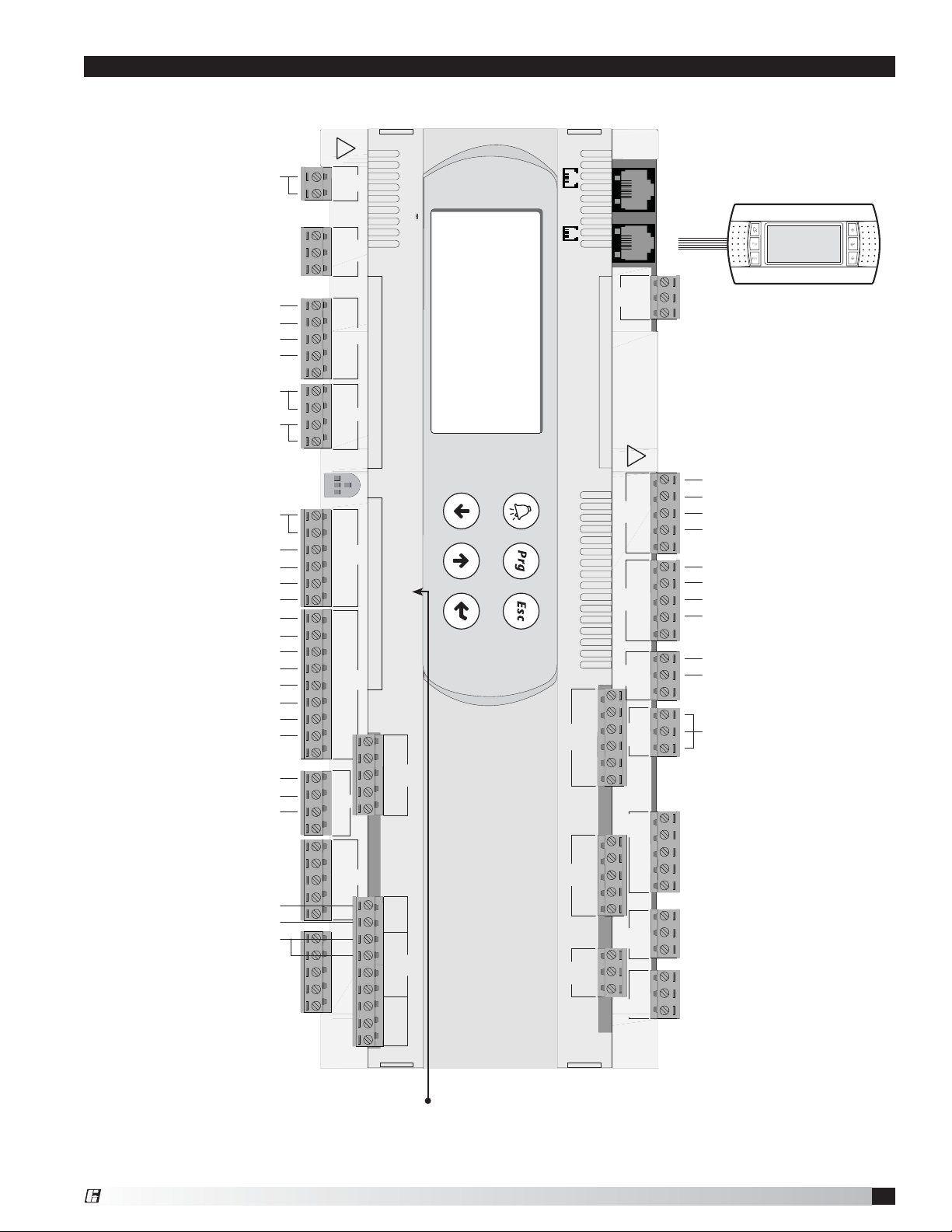
24 VAC to Controller
Small Controller Overview
input: 24V~/ V ; 50 to 60 Hz
max. power: 40 VA/15W
J1J1 J24J24
G
G0
Room RH or Dehumidistat
Room Temperature Sensor
After Cold Coil Temperature Sensor
Sensor B1, B2, B3 Commons
Supply Discharge Temperature Sensor
Outdoor Air Temperature Sensor
24 VAC for Analog Outputs
Energy Wheel Analog Output
Heating Analog Output
Cooling Analog Output
Hot Gas Reheat Analog Output
Supply Fan Proving
Wheel Pressure
Wheel Rotation Alarm
Unit On/Off
Exhaust Fan Proving
Occupied/Unoccupied Input
Dirty Filter
Compressor Limit
+Vterm
GND
+5 VREF
B1
B2
B3
GND
+VDC
B4
BC4
B5
BC5
VG
VG0
Y1
Y2
Y3
Y4
ID1
ID2
ID3
ID4
ID5
ID6
ID7
ID8
IDC1
J10J9
Rx-/Tx-
J11J11
Rx+/Tx+
J2J2 J5J5J4J4J3J3
field card serial card
GND
service card
J12J12 J13J13
J14J14
J15J15
C1
NO1
NO2
NO3
C1
C4
NO4
NO5
NO6
C4
C7
NO7
C7
NO8
C8
NC8
24 VAC When Unit On
Frost Control Enable
Output to Supply Fan
Output to Exhaust Fan
24 VAC from Supply Fan Proving
Heating Enable/Reversing Valve
Compressor Output 1
Compressor Output 2
24 VAC
Output to Dampers
Alarm Dry Contact
Remote Display
(six conductor RJ25 cable)
DDC Controller for Tempered Air Products
6
Optional BACnet, LonWorks and
Modbus cards are located in
Serial Card port
®
Page 7
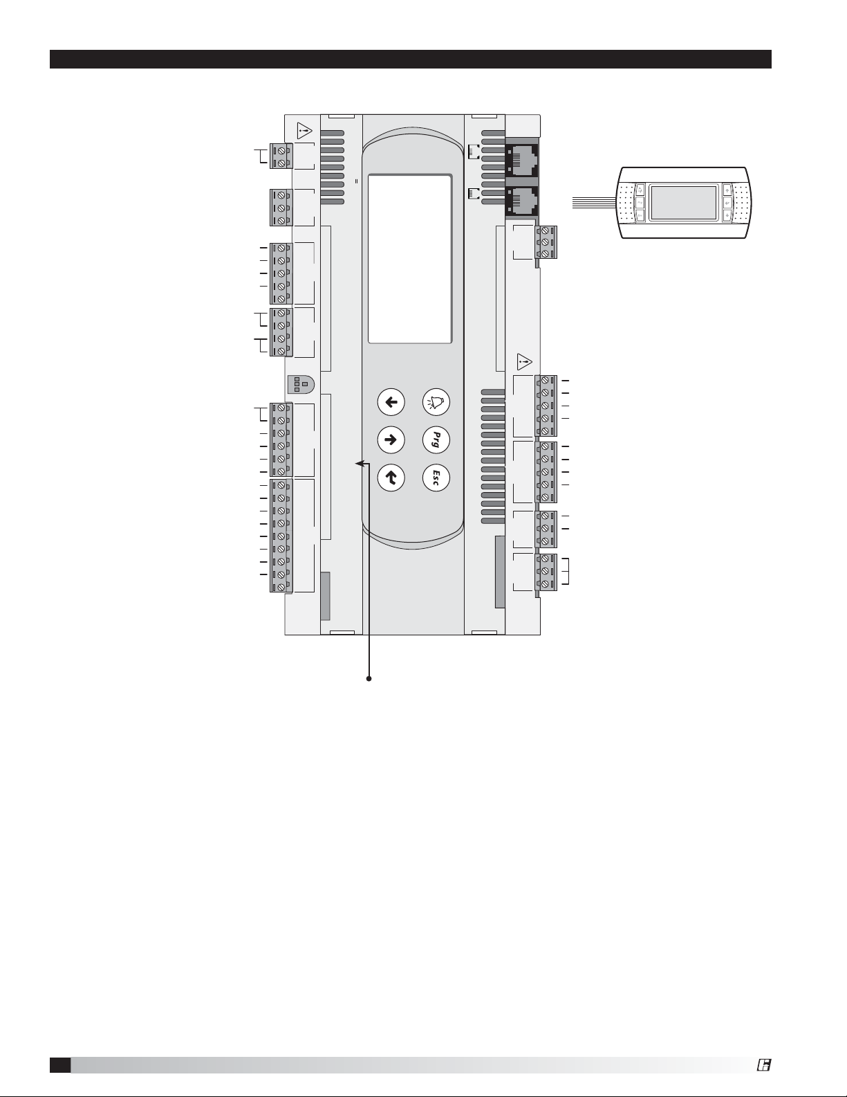
Large Controller Overview
24VAC to Controller
Room RH or Dehumidistat
CO2 Sensor
After Cold Coil Temperature Sensor
Sensor B1, B2, B3 Commons
Supply Discharge Temperature Sensor
Outdoor Air Temperature Sensor
24VAC for Analog Outputs
Outdoor Air Damper Analog Output
Heating Analog Output
Cooling Analog Output
Hot Gas Reheat Analog Output
Supply Fan Proving
Wheel Pressure Limit
Wheel Rotation Alarm
Unit On/Off Input
Exhaust Fan Proving
Occupied/Unoccupied Input
Dirty Filter Input
Compressor Limit
Outdoor Relative Humidity Sensor
Building Pressure Sensor
Duct Pressure Sensor
Supply Fan VFD Output
Exhaust Fan VFD Output
Room Temperature Sensor
G
G0
+V
GND
+5 V
B1
B2
B3
GND
+VDC
B4
BC4
B5
BC5
VG
VG0
Y1
Y2
Y3
Y4
ID1
ID2
ID3
ID4
ID5
ID6
ID7
ID8
IDC1
B6
B7
B8
GND
ID9
ID10
ID11
ID12
IDC9
ID13H
ID13
IDC13
ID14
ID14H
J8
!
max. power: 40 VA/15W
input: 24V~/ V ; 50 to 60 Hz
J1 J24 J2 J3
term
REF
field card serial card
J10J9
Rx-/Tx-
J11
Rx+/Tx+
GND
Remote Display
(six conductor RJ25 cable)
service card
!
J6
J7
J4 J5
ID15H
ID15
IDC15
ID16
ID16H
Y5
Y6
B9
BC9
B10
BC10
ID17
ID18
IDC17
J19
J20
J21
J22
J23
NO14
C14
NC14
NO15
C15
NC15
C16
NO16
NO17
NO18
C16
GND
C1
NO1
J12
NO2
NO3
C1
C4
NO4
J13
NO5
NO6
C4
C7
J14
NO7
C7
NO8
J15
C8
NC8
J16 J17
C9
NO9
NO10
NO11
C9
NO12
C12
NC12
E-
E+
NO13
C13
J18
NC13
24 VAC When Unit On
Wheel Frost Mode
Supply Fan Enable
Exhaust Fan Enable
24 VAC from Supply Fan Proving
Heating Enable/Reversing Valve
Staged Compressor 1
Staged Compressor 2
24 VAC
Economizer Mode/Output to Dampers
Alarm Dry Contact
Optional BACnet, LonWorks and Modbus
cards are located in
Serial Card port
®
DDC Controller for Tempered Air Products
7
Page 8
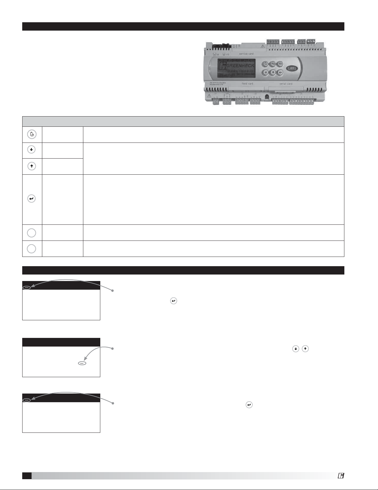
Display Use
The microprocessor controller is located in the unit
control panel. The face of the controller has six keys,
allowing the user to view unit conditions and alter
parameters. The microprocessor controller is preprogrammed with easy to use menus.
To change the display contrast, hold the Enter and
Escape button while pressing the up and down arrows.
A remote mounted display is also available, which
connects via the J10 port. A six wire patch cable is
needed.
Keypad Description
Alarm
Down Arrow
Up Arrow
Enter
Button will blink red, indicating an alarm condition. Press to review current alarms. To review
previous alarms, access the DATA LOGGER through the main menu.
The arrow keys allow the user to scroll through different screens and adjust parameters.
A. In screens with adjustable parameters, pressing the Enter key moves the cursor from
the upper left corner of the screen to the parameter. The arrow keys can then be used to
adjust the parameter.
B. To move to the next parameter on the same screen, press the Enter button.
C. To save the change, press the Enter button until the cursor moves back to the upper left
corner of the screen.
Esc
Escape Allows the user to exit the current menu, jumping to the Main Menu.
Prg
Program
Supply air low limit
Alarm when supply is
below: 35.0º F
Alarm delay: 300s
Supply air low limit
Alarm when supply is
below: 32.0º F
Alarm delay: 300s
Supply air low limit
Alarm when supply is
below: 32.0º F
Alarm delay: 300s
Pressing the Prg (Program) button allows the user to enter the Main Program Menu. Refer to
pages 10 and 11 for Main Program Menu description.
Example of Parameter Adjustment
The cursor always begins in the upper left corner of the display and will be
blinking. Press the
Once the cursor has reached the desired parameter, press the
adjust the value.
When satisfied with the adjustment, press the
When finished, make certain the cursor is in the upper left corner. If the cursor is
not in the upper left corner, the changes will not be saved. The cursor must be in
the upper left corner to enable screen advancement.
key to move the cursor down for parameter adjustment.
key to save the parameter.
keys to
DDC Controller for Tempered Air Products
8
®
Page 9
Examples of Alarms
If an alarm occurs, the
Alarms
Press DOWN to review
current alarm(s).
Press ESC to exit.
Press ALARM to reset.
button will glow red on the controller and the remote display (if installed).
To view alarm, press the button once. This will display the most recent alarm.
Press the
button again to reset the alarm. If the alarm cannot be cleared,
the cause of the alarm has not been fixed. Press the
additional occurring alarms.
buttons to view any
This is an example of an outdoor air sensor failure.
Outside Air Temperature
Sensor B01 Failure
Alarms
No active alarm
Press ENTER
to DATA LOGGER
This screen appears if there are no active alarms.
To view all saved alarms, press the
button to enter the DATA LOGGER. For
more information, see the Data Logger menu.
Examples of Alarms
Outdoor Air Temperature
Sensor Failure
Supply Air Temperature
Sensor Failure
Cold Coil Temperature
Sensor Failure
Room Temperature
Sensor Failure
System has exceeded the
set number of run hours
Supply airflow Indicates a loss of airflow in the supply fan. Alarm & Shutdown
Wheel Pressure
- Dirty Wheel/High CFM
Energy recovery wheel
rotation. Check wheel.
Exhaust Airflow Indicates a loss of airflow in the exhaust fan. Alarm & Shutdown
Filter Alarm Indicates a buildup of pressure across the filters. Alarm only
A compressor limit
switch has tripped
Supply temperature low
limit alarm
Cold Coil Low Limit Indicates a cold coil temperature lower than the cold coil low limit
pCOe Offline Indicates communication with pCOe auxiliary I/O has failed. Alarm only
pCOe - Analog input
probe on channel #
disconnected or broken
Building Pressure Sensor
Failure
Duct Pressure Sensor
Failure
Room Humidity Sensor
Failure
Outdoor Air Humidity
Sensor Failure
CO2 Sensor Failure Failure of CO2 sensor Alarm & minimum fan speed
Failure of outside air temperature sensor. Alarm only
Failure of supply air temperature sensor. Alarm & Shutdown
Failure of after cooling coil air temperature sensor. Alarm only
Failure of room temperature sensor.
(If Unoccupied - Cycle On Room is enabled)
The unit has been operating for a period longer than the
maintenance set point.
Indicates a buildup of pressure across the energy wheel. Alarm only
Indicates a wheel rotation failure. Alarm only
Indicates a high or low refrigerant pressure switch has tripped. Alarm only
Indicates a supply air temperature lower than the supply low limit
set point.
Indicates an analog probe failure on the pCOe. Check integrity of
auxiliary I/O analog probes.
Failure of building pressure sensor Alarm & minimum fan speed
Failure of duct pressure sensor Alarm & minimum fan speed
Failure of room RH sensor Alarm only
Failure of outdoor air humidity sensor Alarm only
Alarm only
Alarm only
Alarm & Shutdown
Alarm & discharge air sensor
lockout
Alarm only
®
DDC Controller for Tempered Air Products
9
Page 10
Press
Prg
to enter menus.
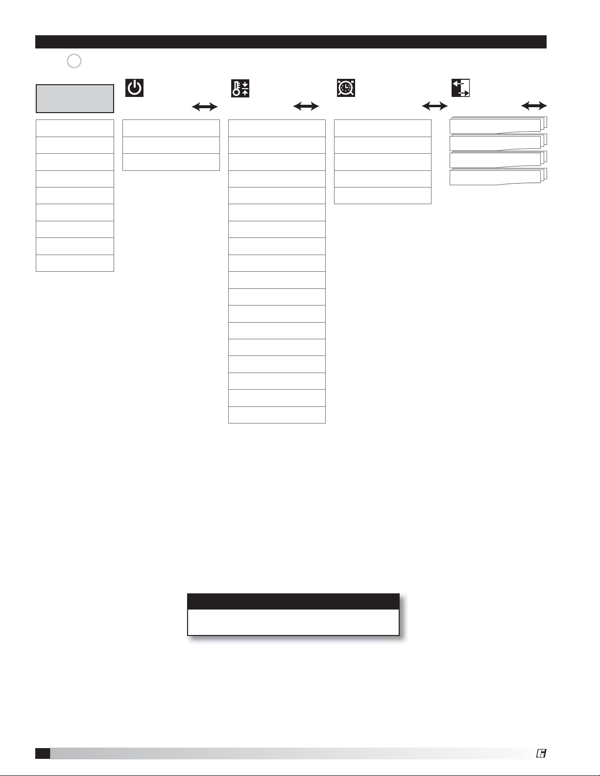
Menu Overview
Main Menu
Main Status Unit On/Off Supply Temp Set Pt Clock Analog Inputs
¬¬¬¬ ¬
Temp Status Unit On/Off Control Room Temp Scheduler Enable Digital Inputs
¬
Occ Override Occupancy Control Cold Coil Set Pt Morning Warm-up Digital Outputs
¬¬ ¬ ¬ ¬
Supply Fan Room Humidity Schedule(s) Analog Outputs
¬¬¬¬
Exhaust Fan Heat Lockout Holiday(s)
¬¬¬
Energy Wheel Cool Lockout
¬¬
Cooling Dehumid Lockout
¬¬
Heating Econ Lockout
¬¬
OA Damper Supply Low Limit
¬¬
On/Off Menu
¬
Setpoint
Clock/Scheduler Input/Output
¬¬ ¬
Defrost
¬
Unoccupied Cycle
¬
Supply Fan VFD
¬
Duct Pressure
¬
Single Zone VAV
¬
Exhaust Fan VFD
¬
Building Pressure
¬
CO2 Set Point
¬
OA Damper Set Point
¬
DDC Controller for Tempered Air Products
10
NOTE
Your controller may not show all menus
depending on unit configuration.
®
Page 11
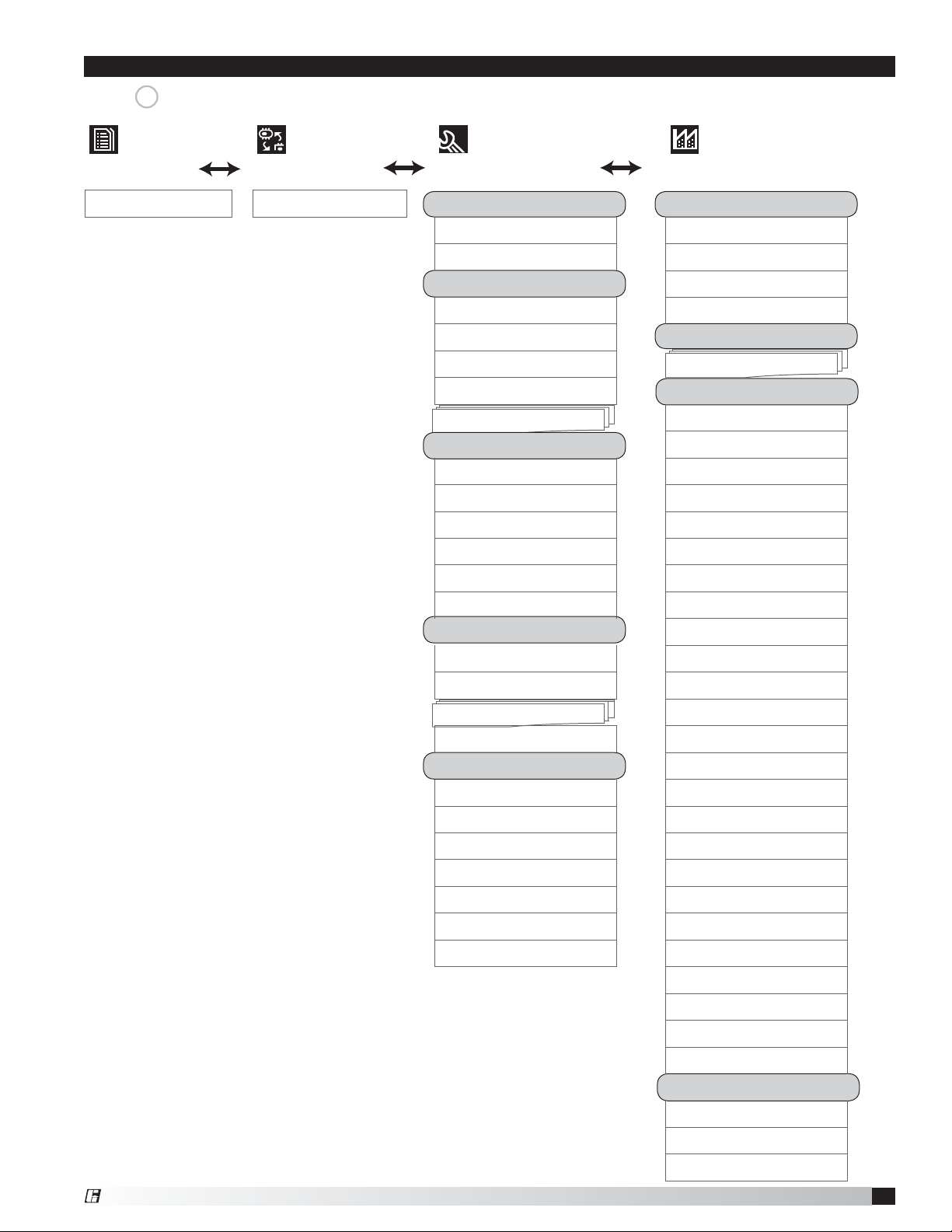
Menu Overview
Press
Data Logger Board Switch Service Manufacturer
¬¬
Prg
to enter menus.
Alarms Board Switch Set Information Configuration
Information Unit Code
¬¬
Information2 Expansion I/O
¬¬
Overrides pLAN Comm
Analog Inputs Field Card Comm
¬¬
Analog Outputs I/O Config
¬
Digital Inputs Inputs/Outputs
¬¬
Digital Outputs Factory Settings
¬
Components Economizer
¬¬
BMS Config Defrost Cycle
Protocol Cooling Control
¬¬
Modbus Comp Rotation
¬¬
BACnet MSTP Digital Scroll
¬¬
BACnet TCP/IP Comp Timers
¬¬
BACnet TCP/IP Comp Staging
¬¬
BACnet R/W Heat Control
¬¬
Service Settings Heater Reheat
Working Hours Heater Reheat 2
Maintenance Hours Hot Gas Control
¬¬
Probe Adjustment Hot Gas Timers
Analog Inputs Hot Gas Setup
¬¬
Password/Default SA Reset Control
Service Password Heat/Cool Delay
¬¬
Service Restore Damper Delay
¬¬
Prg Menu Lock Unocc Setup
¬¬
¬
¬
¬
¬
¬
¬
Damper Delay
¬
Air Proving
¬
Fan Delay
¬
Rotation Delay
¬
CO2 Control
¬
Duct Pressure
¬
Building Pressure
¬
Units / Display
¬
Initialization
Manf Restore
¬
Manf Password
¬
Factory Restore
¬
®
DDC Controller for Tempered Air Products
11
Page 12

Main Menu Overview
The microprocessor controller will revert to a default main menu loop. This loop includes several screens to view the
operating conditions of the unit. Scroll through the menu screens by using the
line border are dependent upon an optional accessory and may not always appear.
keys. Screens with a dashed
TIME DATE UNIT##
®
TAP v2.10 GWY1X000XXXX
STATUS LINE
TIME DATE UNIT##
Supply Air: 000.0°F
Outside Air: 000.0°F
OA Humidity 00.0%
Cold Coil: 000.0°F
Room Temp: 000.0°F
Room Humidity: 00.0%
STATUS LINE
Occupancy Override
Clock Override: OFF
Override Time: 1 hr
THE INITIAL MENU SCREEN DISPLAYS THE PROGRAM VERSION, UNIT CODE AND STATUS
LINE. THE STATUS LINE DISPLAYS WHICH MODE THE UNIT IS IN.
Possible modes include:
• Initial Delay
• Opening Dampers
• Exhaust Fan Starting
• Supply Fan Starting
• System On
• Defrost Mode Active
• Sys On - Econ+Cooling
• Sys On - Economizer
• Sys On - Heating
• Sys On - Cooling
• Sys On - Dehumidifying
• Sys On - Dehumid & Reheat
• Unoccupied - Unit On
• Unoccupied - Unit Off
• Unoccupied - Dehumid
• Unoccupied - Dehumid & Reheat
• Unoccupied - Heating
• Unoccupied - Cooling
• Manual Override
• Remote Off
• Press Alarm Button!!!
• Temp Occupied
THE SENSOR STATUS SCREEN DISPLAYS REAL TIME CONDITIONS FROM THE SENSORS
LOCATED IN THE UNIT AND THE ROOM (IF INSTALLED).
OCCUPANCY OVERRIDE (IF UNOCCUPIED)
If the unit is currently unoccupied, the occupancy can be temporarily overridden
for a period of Override Time. The Override Time parameter can be set from one
to three hours.
Supply Fan Status
Supply Fan Ramp: 0%
(0%=Min Speed by VFD)
Duct Ps Control
Duct Pressure: 0.00”wc
STATUS LINE
Exhaust Fan Status
Exhaust Fan Ramp: 0%
(0%=Min Speed by VFD)
Building Ps Control
Building Ps: +.000”wc
STATUS LINE
Energy Recovery
Wheel: 100% Speed
Wheel Differential
Pressure Is: Normal
Preheater: OFF
STATUS LINE
SUPPLY FAN STATUS. (IF EQUIPPED WITH VFD)
If equipped with a supply fan VFD, this screen will display the supply fan ramp
being sent from the controller to the VFD. The minimum and maximum speeds are
set in the VFD (See unit Installation and Operation Manual for VFD programming).
The controller can modulate the fan between the min and max speeds via an
analog output. This screen also displays the method of fan control and the
parameter it is controlling.
Possible methods include: Constant Speed, Duct Pressure Control, Building
Pressure Control, CO2 Control, and Single Zone VAV.
EXHAUST FAN STATUS. (IF EQUIPPED WITH VFD)
If equipped with an exhaust fan VFD, this screen will display the exhaust fan ramp
being sent from the controller to the VFD. The minimum and maximum speeds are
set in the VFD (See unit Installation and Operation Manual for VFD programming).
The controller can modulate the fan between the min and max speeds via an
analog output. This screen also displays the method of fan control and the
parameter it is controlling.
Possible methods include: Constant Speed, Building Pressure Control, Outdoor
Air Damper Tracking, and Supply Fan Tracking.
ENERGY RECOVERY WHEEL STATUS. (IF EQUIPPED)
If selected with a preheater, the status will also be displayed.
DDC Controller for Tempered Air Products
12
®
Page 13

Cooling Status
Cooling Control: 000%
Compressor D 1 2
STATUS LINE
COOLING STATUS IS DISPLAYED, ALONG WITH COMPRESSOR OPERATION. (IF EQUIPPED)
This screen appears if a cooling option is provided.
Chilled Water: The Cooling Control % is directly proportional to the 0-10 VDC
output signal.
0% Cooling = 0 VDC
100% Cooling = 10 VDC
The cooling control output can be configured to DIRECT / REVERSE acting,
along with the minimum and maximum output voltages by entering the
MANUFACTURER menu.
Packaged DX Cooling: The Cooling Control displays internal cooling ramp as a
percent. Compressor operation is displayed when engaged.
• D = Digital Scroll Compressor Operation
• 1 = First Staged Compressor Operation
• 2 = Second Staged Compressor Operation
Heat Pump Cooling: The Cooling Control displays internal cooling ramp as a
percent. Compressor operation is displayed when engaged.
• 1 = First Staged Compressor Operation
• 2 = Second Staged Compressor Operation
Heating Status
Heater Control: 000%
Hot Gas Reheat: 000%
Staged reheat is: ON
Compressor: 1 2
STATUS LINE
HEAT AND REHEAT OPERATION IS DISPLAYED. (IF EQUIPPED)
Heater Control displays the proportional percentage of the heater analog output.
Electric Heater: The Heater Control % is proportional to the 0-10 VDC signal
being sent to the SCR controller, located in the electric heater control center.
0% Heating = 0 VDC - 0 kW output
100% Heating = 10 VDC - Max kW output
Hot Water: The Heater Control % is proportional to the 0-10 VDC signal being
sent to the heating control valve (BY OTHERS). The heating control output can be
configured to DIRECT / REVERSE acting, along with the minimum and maximum
output voltages by entering the MANUFACTURER menu.
0% Heating = 0 VDC
100% Heating = 10 VDC
Indirect Gas: The Heater Control % is proportional to the 0-10 VDC signal being
sent to the indirect gas furnace controller, located in the indirect gas control
center. The first stage is on at 1% Heater Control. The furnace will then modulate
proportionally from minimum to maximum capacity.
0% = 0 VDC – OFF
1% = 0 VDC – MINIMUM TURNDOWN ENABLED
1 - 100% = 0 - 10 VDC = FURNACE MODULATION
Heat Pump Heating: The Heater Control % displays internal heating ramp as a
percent. Compressor operation is displayed when engaged.
• 1 = First Staged Compressor Operation
• 2 = Second Staged Compressor Operation
Hot Gas Reheat:
If hot gas reheat is staged control:
“Staged reheat is: ON/OFF” will indicate operation.
If hot gas reheat is modulating bypass damper control:
0% = OFF
1% - 100% = 4 - 10 VDC = AIRFLOW DAMPER MODULATION
If hot gas reheat is modulating valve control:
0% = OFF
1% - 100% = 0 - 10 VDC = HOT GAS REHEAT VALVE MODULATION
®
DDC Controller for Tempered Air Products
13
Page 14
Outdoor Damper Status
Damper Position: 50%
Active on Minimum OA%
CO2 Level: 0
STATUS LINE
PPM
OUTDOOR AIR DAMPER STATUS . (IF EQUIPPED WITH MODULATING OUTDOOR AND
RECIRCULATED AIR DAMPERS)
This screen will display the outdoor air damper position commanded by the
controller and which method the damper position is actively utilizing.
Possible methods include: Active on Minimum OA%, Active on Economizer, Active
on CO2 and Active on BMS.
Menus
The controller is equipped with several menus to help guide users with altering program parameters. The following
menus can be accessed by pressing the
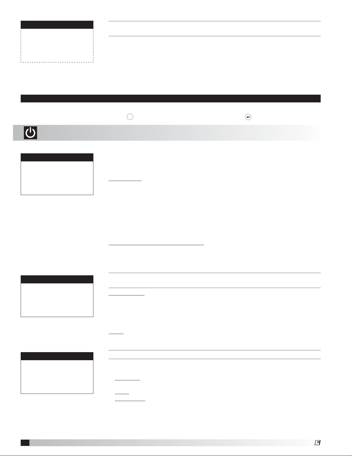
A. On/Off Unit
Unit On/Off
The On/Off Unit menu allows the user to view the detailed On/Off status of the
controller.
The unit ships from the factory in a disabled state. To allow the unit to operate,
Prg
key. To enter the desired menu, press the key.
the controller must receive a run command from digital input ID4. Jumper unit
Actual state:
Off by DIG INPUT (ID4)
Change to: SWITCH ON
*Power ID4 to start…
terminals R - G to allow the unit to operate.
Actual State: The controller may be in following On/Off states:
a. Unit On - Unit is ON, functioning normally.
b. Off by ALARM - Unit is OFF due to an alarm. View alarms by pressing
ALARM button.
c. Off by PLAN - Unit is OFF by pLAN network.
d. Off by BMS - Unit is OFF by BMS command
e. Off by UNOCCUPIED - Unit is OFF by unoccupied command.
f. Off by DIGITAL INPUT (ID4) - Unit is OFF by digital input 4 (ID4).
g. Off by KEYPAD - Unit is commanded OFF by this screen.
Change to (Switch Off/Switch On): Enables user manually turn unit On/Off via
display. Unit terminal G must have 24 VAC power to enable the unit.
Unit ON/OFF Control
Enable unit OnOff
By digit input: Yes
By BMS: No
Occupancy Control
Type: Unit OFF
Source: Input ID6
DDC Controller for Tempered Air Products
14
THIS SCREEN ALLOWS THE USER TO ADJUST WHICH SYSTEM CONTROLS THE UNIT
ON/OFF STATE.
Digital Input: Default to YES. Unit terminal G must have 24 VAC power to enable
the unit.
The user can also use the BMS or internal time clock to command the unit
On/Off state. If scheduling is desired, go to the Clock/Scheduler menu to set
a schedule.
BMS: YES allows BMS to control unit On/Off state.
THIS SCREEN DISPLAYS WHAT THE UNIT WILL DO IN UNOCCUPIED MODE.
This screen allows the user to select the source of determining occupancy. The
factory default is terminal ID6 on the controller.
Input ID6: Typically used with a remote time clock, motion sensor or switch
(default).
BMS: BMS control (see Points List). BMS can be overridden with ID6.
Time Clock: Internal time clock (Scheduler). See Clock/Scheduler menu for
more information. The Scheduler can be overridden with digital
input ID6.
®
Page 15

B. Setpoint
The Setpoint menu allows the user to view and adjust temperature related
parameters.
Supply Temp Set Point
Active: 70.0°F
Source: Local 70.0°F
Max: 90.0°F
Min: 55.0°F
Supply Temp Set Point
Active: 72.0°F
Source: BMS 72.0°F
Max: 90.0°F
Min: 55.0°F
Supply Temp Set Point
Active: 55.0°F
Source: OA Reset
Outside Supply
55.0°F 70.0°F
65.0°F 55.0°F
THIS SCREEN DISPLAYS THE SUPPLY AIR TEMPERATURE SET POINT SCREEN
PARAMETERS.
When operating, the unit will control the heating and cooling to maintain the active
supply temperature set point. The active set point will be determined by the set
point source selection.
Possible Set Point Sources:
Local – The supply set point will be constant set from screen. (exp. 72°F).
BMS – The BMS can directly control the supply air temperature set point (requires
BMS communication option).
OA-Reset -The controller monitors the outdoor air temperature and adjusts the
desired supply temperature set point accordingly. For example, when the outdoor
air is below 55°F, the controller will change the supply set point to 70°F. If the
outdoor air is above 65°F, the controller will change the supply set point to 55°F.
If the outdoor air temperature is between 55°F and 65°F, the supply set point
changes according to the outdoor air reset function. A visual representation of the
outdoor air reset function is shown below.
Outdoor Air Reset Function
75°
70°
65°
Supply Temp Set Point
Active: 72.0°F
Source: Room Reset
Max: 90.0°F
Min: 55.0°F
Room Temp Set Point
Active: 72.0°F
Source: Local 72.0°F
Room Temp Set Point
Active: 72.0°F
Source: BMS 72.0°F
60°
55°
50°
Supply Air Set Point (°F)
45°
50° 55° 60° 65° 70°
Outside Air Temperature (°F)
Room-Reset – The controller will reset the supply air temperature set point to
maintain the room temperature set point (requires room temp sensor). See the
Room Temp Set Point screen in this menu for more information.
THIS SCREEN DISPLAYS THE ROOM TEMP SET POINT.
This screen only appears if Room Reset is selected as the supply set point source,
and a room temperature sensor is wired into the controller.
The unit will reset the supply air temperature set point to maintain the room temp
set point.
Possible Set Point Sources:
Local – The room set point will be constant set from screen (exp. 72°F).
BMS – The BMS can directly control the room temperature set point (requires
BMS communication option).
®
DDC Controller for Tempered Air Products
15
Page 16

Cold Coil Set Point
Active: 55.0°F
Source: Local 55.0°F
Max: 55.0°F
Min: 50.0°F
Cold Coil Set Point
Active: 55.0°F
Source: BMS 55.0°F
Max: 55.0°F
Min: 50.0°F
Cold Coil Set Point
Active: 55.0°F
Source: Room RH 55.0°F
Max: 55.0°F
Min: 50.0°F
Cold Coil Set Point
Active: 55.0°F
Source: Room DewPt 55.0°F
Max: 55.0°F
Min: 50.0°F
THIS SCREEN DISPLAYS THE TEMPERATURE SET POINTS FOR THE COOLING COIL.
This screen only appears if the unit is equipped with cooling.
When in dehumidification mode, the controller will maintain the active cold coil set
point. The active set point will be determined by the set point source selection.
Possible Set Point Sources:
Local – The supply set point will be constant set from screen (exp. 55°F). If a
dehumidistat was provided with the unit, the active set point will be reset to the
minimum set point.
BMS – The cold coil leaving air temperature set point can be adjusted over the
BMS via the Dehumidification Set Point (see Points List).
Room RH – The controller will reset the cold coil temperature set point to
maintain the room relative humidity set point (requires room relative humidity
sensor). See the Room RH Set Point screen in this menu for more information.
Room Dew Point – The controller will reset the cold coil temperature set point to
maintain the room dew point set point (requires room temperature and relative
humidity sensors). See the Room Dew Point Set Point screen in this menu for
more information.
Room Humidity SetPoint
Active: 55.0%
Source: Local 55.0%
Room Humidity: 50.0%
Room DewPt Set Point
Active: 55.0°F
Source: Local 55.0°F
Room Dew Point: 46.0°F
THIS SCREEN DISPLAYS THE ROOM RELATIVE HUMIDITY SET POINT.
This screen only appears if Room RH is selected as the cold coil set point source,
and a room relative humidity sensor is wired into the controller.
The unit will reset the cold coil temperature set point to maintain the room relative
humidity set point.
Possible Set Point Sources:
Local – The room set point will be constant set from screen (exp. 55% RH).
BMS – The cold coil leaving air temperature set point can be adjusted over the
BMS via the Dehumidification Set Point (see Points List).
THIS SCREEN DISPLAYS THE ROOM DEW POINT SET POINT.
This screen only appears if Room Dew Point is selected as the cold coil set point
source, and a room relative humidity sensor and room temperature sensor are
wired into the controller.
The unit will reset the cold coil temperature set point to maintain the room dew
point set point.
Possible Set Point Sources:
Local – The room set point will be constant set from screen (exp. 55°F)
BMS – The cold coil leaving air temperature set point can be adjusted over the
BMS via the Dehumidification Set Point (see Points List).
DDC Controller for Tempered Air Products
16
®
Page 17

Heating Lockout
Lockout heating when outside
above: 70.0°F
Differential: 2.0°F
THIS SCREEN DISPLAYS THE HEATING LOCKOUT.
This screen only appears if the unit the unit is equipped with heating.
There is a built in hysteresis of 2°F which prevents the heating from short cycling.
The hysteresis is similar to a dead-band above and below the lockout set point.
(Example: If Lockout = 70°F, heating is locked out above 72°F and enabled below
68°F outside air temperature.)
Cooling Lockout
Lockout cooling when outside
below: 55.0°F
Differential: 2.0°F
Dehumidification lock
Lockout dehumidification until
outside air is 10.0°F above
cold coil set point.
Economizer Lockout
Type: DryBulb+DewPoint
Below: 40.0°F (Dry Bulb)
Above: 75.0°F (Dry Bulb)
Above: 55.0°F (Dew PT)
Differential: 2.0°F
THIS SCREEN DISPLAYS THE COOLING LOCKOUT.
This screen only appears if the unit is equipped with cooling.
There is a built in hysteresis of 2°F which prevents the cooling from short cycling.
The hysteresis is similar to a dead-band above and below the lockout set point.
(Example: If Lockout = 55°F, cooling is locked out below 53°F and enabled above
57°F outside air temperature.)
THIS SCREEN DISPLAYS THE TEMPERATURE DIFFERENCE AT WHICH THE
DEHUMIDIFICATION MODE IS LOCKED OUT. (FACTORY DEFAULT = 10°F)
This screen only appears if the unit is equipped with cooling.
This setting prevents the unit from operating in dehumidification mode when the
outdoor air conditions are relatively cool. Example: If the cold coil set point is 55°F,
dehumidification mode cannot operate until the outdoor air is at least 65°F.
THIS SCREEN DISPLAYS THE ECONOMIZER LOCKOUTS.
This screen only appears if economizer functionality was provided with the unit.
The lockouts determine when economizer is available, based on the outdoor
air temperature or outdoor air temperature and humidity. The low temperature
lockout prevents outdoor air from entering the unit at too cold of a temperature
that could freeze coils. There is a built in differential that is similar to a deadband,
above and below the lockout set point.
If an outdoor relative humidity sensor was provided with the unit, the user can
change the economizer lockout control type.
Possible Control Types:
DryBulb – The economizer will be locked out based on the outdoor dry-bulb
temperature.
DryBulb+DewPoint (preferred) – The economizer will be locked out based on the
outdoor dry-bulb temperature and a calculated outdoor air dew point.
DryBulb+Enthalpy – The economizer will be locked out based on the outdoor
dry-bulb temperature and a calculated outdoor enthalpy.
DryBulb+WetBulb – The economizer will be locked out based on the outdoor drybulb temperature and a calculated outdoor air wet-bulb temperature.
Supply air low limit
Alarm when supply is
below: 35.0°F
Alarm delay: 300s
®
THIS SCREEN DISPLAYS THE LOW SUPPLY AIR TEMPERATURE LIMIT.
If the unit supply air temperature falls below Supply Air Low Limit for a period of
Alarm Delay, the unit will shut down and an alarm will be signaled. The purpose of
the supply low limit is to protect the building and contents from cold supply air. It
is NOT designed to protect the air-handling unit.
If the unit does not have chilled water (CW) or hot water (HW) coils, it should not
need additional protection from freezing. If the unit does have CW or HW coils,
field provided coil freeze protection may be necessary.
DDC Controller for Tempered Air Products
17
Page 18

Defrost
Allow wheel defrost
mode when outside
is below: 05.0°F
THIS SCREEN DISPLAYS THE TEMPERATURE AT WHICH THE UNIT WILL ENABLE FROST
CONTROL MODE IF NECESSARY. (FACTORY DEFAULT = 5°F)
This screen only appears if the unit has an energy recovery wheel and a frost
control method was provided with the unit.
Upon sensing a high differential pressure across the energy wheel, the unit will go
into defrost if the outside air temperature is below this temperature setting.
UnOcc Fan Cycle Setup
UnOcc Room Set Points:
Heating: 65.0°F
Cooling: 80.0°F
Room RH: 50.0%
Temp Diff: 5.0°F
Dehumid Diff: 5.0%
THIS SCREEN DISPLAYS THE ROOM SET POINTS DURING THE UNOCCUPIED MODE.
This screen only appears if an unoccupied recirculation damper was provided with
the unit. Room sensor(s) must be wired to the controller.
In the unoccupied mode, the unit will monitor the room temperature and humidity
sensors. The unit will cycle on to maintain the unoccupied room set points by
tempering recirculated air. The differential prevents short cycling. For example, in
heating, the unit cycles on at 60°F and turns off at 65°F.
Supply Fan Speed SetPt
Active: 100%
THIS SCREEN DISPLAYS THE SUPPLY FAN SPEED SET POINTS.
This screen only appears if equipped with a supply fan VFD controlled by
microprocessor.
Source: Local 100%
UnOccupied Cycle 100%
(0%=Min Speed by VFD)
The Speed Set Point is the proportional percentage of the analog output from the
controller to the VFD.
0% Speed = Min Speed (determined by VFD)
100% Speed = Max Speed (determined by VFD)
UnOccupied Cycle - The supply fan speed when the unit is on during unoccupied
cycle times.
Possible Set Point Sources:
Local – The fan speed will be constant set from screen (exp. 100%).
BMS – The BMS can directly control the fan speed (requires BMS communication
option).
Duct Pressure – Fan speed is determined by duct pressure control loop.
Building Pressure - Fan speed is determined by building pressure control loop.
CO2 - Fan speed is determined by CO2 control loop.
DDC Controller for Tempered Air Products
18
®
Page 19

ExhaustFan Speed SetPt
Active: 100%
THIS SCREEN DISPLAYS THE EXHAUST FAN SPEED SET POINTS.
This screen only appears if equipped with an exhaust fan VFD controlled by
microprocessor.
Source: Local 100%
(0%=Min Speed by VFD)
The Speed Set Point is the proportional percentage of the analog output from the
controller to the VFD.
0% Speed = Min Speed (determined by VFD)
100% Speed = Max Speed (determined by VFD)
Possible Set Point Sources:
Local – The fan speed will be constant set from screen (exp. 100%).
BMS – The BMS can directly control the fan speed (requires BMS communication
option).
Building Pressure - Fan speed is determined by building pressure control loop.
Supply Fan Tracking – Exhaust speed proportionally tracks supply speed.
ExhaustFan Speed SetPt
Active: 0%
Source: OA Damper Trk
OA Damper EF Speed
Min OA 0%
Max CO2 50%
Max Econ 100%
ExhaustFan Speed SetPt
Active: 0%
Source: OA Damper Trk
OA Damper EF Speed
30% 0%
Max BMS 50%
Max Econ 100%
Outdoor Air Damper Tracking – The exhaust fan will proportionally track the
outdoor air damper, between a minimum and maximum position.
Normal Operation: During non-economizer operation, the exhaust fan will track
the outdoor air damper between the minimum outdoor air position (Min OA) and
the maximum sequence position (Max CO2 or Max BMS). *Note that if the OA
Damper Set Point is controlled by the BMS, the exhaust fan tracking algorithm
references an adjustable minimum position on the display. In this case, the
outdoor air damper must open above this position before the exhaust fan begins
increasing speed.
Economizer Operation: During economizer operation, the exhaust fan will track
the outdoor air damper between the minimum outdoor air position and the
maximum economizer position (Max Econ).
džŚĂƵƐƚ&ĂŶdƌĂĐŬŝŶŐŽĨKĂŵƉĞƌWŽƐŝƟŽŶ
100%
50%
džŚĂƵƐƚ&ĂŶ^ƉĞĞĚ
0%
0% (MiŶ Speed)
ĐŽŶŽŵŝnjĞƌ
KƉĞƌĂƟŽŶ
Normal
KƉĞƌĂƟŽŶ
100% (Max Speed)
KƵƚĚŽŽƌĂŵƉĞƌWŽƐŝƟŽŶ
®
DDC Controller for Tempered Air Products
19
Page 20

Duct Pressure SetPt
Active: 0.25” wc
Source: Local 0.25” wc
THIS SCREEN DISPLAYS THE DUCT PRESSURE SET POINT.
This screen only appears if equipped with a duct pressure sensor.
The unit will modulate the supply fan to maintain the local duct pressure set point.
Set point source must be changed to BMS to allow BMS control.
Duct Ps: 0.18” wc
Single Zone VAV Setup
Supply Fan Speeds
Cooling Heating
Min: 0% 0%
Max: 100% 100%
Cooling Fan Delay: 180s
CO2 Set Point
Active: 1000PPM
Source: Local 1000PPM
CO2 Level: 66PPM
THIS SCREEN DISPLAYS THE SINGLE ZONE FANS SPEED PAR AMETERS.
This screen only appears if the supply fan VFD control is configured as Single
Zone VAV. A room temperature sensor is required.
When the unit is configured for Single Zone VAV, the heating, cooling and
economizer are controlled to maintain the active supply air temperature set point,
which is reset based on room temperature reset. The supply fan is modulated in
addition to the supply air temperature to satisfy the room temperature set point.
The minimum and maximum supply fan speed limits can be set during space
cooling and heating.
Space Cooling: When the room requires cooling (the room is warmer than room
temperature set point), the supply air temperature set point will reset as low as the
minimum supply temperature set point (see Supply Temp Set Point screen) to try
to cool the space. If further cooling is required, after the Cooling Fan Delay, the
supply fan will increase in speed to deliver more cooling to the space.
Space Heating: When the room requires heating (the room is cooler than the room
temperature set point), the supply air temperature set point will reset as high as
the maximum supply temperature set point (see Supply Temp Set Point screen)
and the supply fan will increase in speed to deliver more heating to the space.
THIS SCREEN DISPLAYS THE CO2 SET POINT.
This screen only appears if equipped with a CO2 sensor.
Depending on unit configuration, the unit will either modulate the supply fan or
outdoor air damper to maintain the CO2 set point.
Set point source must be changed to BMS to allow BMS control.
Building Press SetPt
Active: +0.010” wc
Source: Local +0.010” wc
Building Ps: +0.010” wc
DDC Controller for Tempered Air Products
20
THIS SCREEN DISPLAYS THE BUILDING PRESSURE SET POINT.
This screen only appears if equipped with a building pressure sensor.
Depending on unit configuration, the unit will either modulate the exhaust or
supply fan to maintain the local building pressure set point.
Set point source must be changed to BMS to allow BMS control.
®
Page 21

OA Damper Set Point
Active: 40%
Source: Local 40%
Max Econ: 100%
OA Damper Set Point
Active: 50%
Source: SF RESET
SupplyFan: 0% 100%
Min OA: 50% 40%
Max Econ: 100%
OA Damper Set Point
Active: 30%
Source: DCV CO2
SupplyFan: 0% 100%
Min OA: 30% 20%
Max CO2: 50% 40%
Max Econ: 100%
OA Damper Set Point
Active: 25%
Source: BMS 25%
Max BMS: 50%
Max Econ: 100%
THIS SCREEN DISPLAYS THE OUTDOOR AIR DAMPER SET POINT.
This screen only appears if equipped with a modulating outdoor air and
recirculating damper.
The set point is the proportional percentage of the outdoor air damper being
open.
0% = Full recirculation air
100% = Full outdoor air
Minimum Position – When in the occupied mode, the Active set point will be equal
to a local minimum OA set point, which may be constant or reset by fan speed
if equipped with a modulating supply fan. The OA damper set point can then
be further adjusted between the minimum OA and maximum OA settings with
sequences such as DCV CO2, Building Pressure and Economizer.
Maximum Position – Each sequence that can adjust the OA damper set point
contains a maximum position to prevent excess OA. The Active set point will be
determined based on the greatest demand of the configured sequences. For
example, if a unit is equipped with a DCV CO2 and an economizer sequence,
the OA damper set point will react to an economizer demand even if the CO2 set
point is satisfied. Likewise, if economizer is not available but CO2 is above set
point, the OA damper will open to satisfy the CO2 set point.
Supply F an Reset of OA Damper PosiƟon
100%
Max Econ
50%
Max CO2
Min OA
OA Damper PosiƟon Open %
0%
0% (Min Speed)
100% (Max Speed)
Supply F an S peed %
Economizer – The Active set point will be reset based on Economizer demand,
between the minimum and maximum positions.
Possible Set Point Sources:
Local – The minimum outdoor air percentage is constant, set by the controller.
SF Reset – The min and max positions are reset by the supply fan speed.
BMS – The BMS can directly control the OA damper position up to the Max BMS
position.
Building Pressure – Damper position is reset by a building pressure control loop.
DCV CO2 – Damper position is reset by a demand-controlled ventilation control
loop based on room CO2 levels.
®
DDC Controller for Tempered Air Products
21
Page 22

C. Clock/Scheduler
The Clock/Scheduler menu allows the user to view and alter the time and date.
The user can also add up to seven schedules for occupancy requirements.
Set Date & Time
Day: Monday
Date: MM/DD/YY
Hour: 15:30
Scheduler
Number of schedules: 0
Holidays
Holiday = unoccupied mode
for 24 hours.
Number of Holidays: 0
Morning Warm-up
Morning Warmup Off
Temperature Diff: 2.0°F
THE CLOCK SCREEN ALLOWS THE USER TO ADJUST THE TIME AND DATE.
THIS SCREEN ALLOWS THE USER TO ADD THE NUMBER OF UNOCCUPIED SCHEDULES
AND HOLIDAYS.
The Number of Schedules corresponds to the number of unoccupied periods the
user wishes to add. By setting the number of schedules to a value greater than
zero, the unoccupied mode will automatically be set to time clock.
A holiday is a single occurrence in which you would like the unit to be unoccupied
for 24 hours. A maximum of 15 holidays can be set. Holidays must be
reconfigured each year.
THIS SCREEN ALLOWS THE USER TO ENABLE THE MORNING WARM-UP SEQUENCE AND
THE DIFFERENTIAL REQUIRED TO ALLOW THE SEQUENCE TO OCCUR.
This screen only appears if Unoccupied Tempering is available.
The morning warm-up sequence calculates the time required to temper the space
to the occupied set point prior to occupancy. This sequence is limited between 10
to 60 minutes. The controller will re-evaluate the heating and cooling rate daily to
continually adjust to the changing climate.
Scheduler
Schedule #: #
Time On: 07:00
Time Off: 05:00
Days Enabled: MTWTFSS
Holiday #1
Month: MM
Day: DD
Unoccupied for 24 hrs
D. Input/Output
Analog Input
Outside Temperature
Input B01: 75.0°F
E. Data Logger
THIS SCREEN ALLOWS THE USER TO ADJUST SCHEDULES.
This screen only appears if a Schedule was added in the screen above.
The program supports up to seven separate schedules. Each schedule will
require the user to enter a Time On, Time Off and which days the schedule is
applicable for.
THIS SCREEN ALLOWS THE USER TO SET HOLIDAY DATES (IF ENABLED).
This screen only appears if Holidays are enabled.
The internal time clock will go into unoccupied mode as long as the date is equal
to the holiday date (always a 24 hour period).
The Input/Output menu allows the user to quickly view the status of the controller
inputs and outputs.
To manually control I/O values, go to the Service menu > Overrides.
Similar screens appear for all controller inputs and outputs.
Your controller may not utilize all equipped of the inputs and outputs
shown. See unit wiring diagram for your specific configuration.
The Data Logger menu allows the user to view up to 100 past alarms.
13:21:04 MM/DD/ YY
OA TEMP SENSOR
Outside Air T: -623.3
Discharge T: 52.8
Cold Coil T: 55.9
Room T: 72.5
SYS ON-HEATING
DDC Controller for Tempered Air Products
22
THIS SCREEN IS AN EXAMPLE OF A RECORDED ALARM.
The unit conditions are displayed for past alarm events. The date, time,
temperatures and unit status are recorded.
To clear recorded alarms, press
Prg
and
Esc
simultaneously.
®
Page 23

F. Board Switch
The Board Switch menu allows the user to jump between different controllers with
a remote display. This requires a remote display, along with additional controllers,
set-up in a pLAN network. A pLAN can consist of up to 32 devices, in different
combinations, but a maximum of 31 controllers.
Board Switch
Unit Address: 1
Switch to unit: 1
1. . . . . . . . . . 16
17 . . . . . . . . . 32
The Service menu allows the user to access several sub-menus regarding controller
information, controller overrides, operating hours, BMS configuration, I/O manual
G. Service
management and Probe Adjustment. The user can also change the default Service
Password (1000) by accessing the Service Settings sub-menu. By accessing the
BMS Config sub-menu, the user can adjust BMS protocol settings. (BACnet®,
LonWorks®, Modbus®)
G. Service
a. Information
Information
Greenheck Fan
Code: GWY1X000XXXX
Ver.2.10 4/1/14
Manual: 475595
Bios: 5.18 11/17/10
Boot: 4.03 07/03/06
WHEN VIEWING THIS SCREEN FROM A REMOTE DISPLAY, THE USER IS ABLE TO CHANGE
WHICH CONTROLLER’S MENU SHOULD BE DISPLAYED.
Unit Address: The pLAN address of the controller the display is currently
accessing.
Switch to unit: The pLAN address of the controller the display would like to
access.
ENTERING THE INFORMATION SUB-MENU WILL DISPLAY INFORMATION ABOUT THE
CONTROLLER AND THE PROGRAM LOADED ON THE CONTROLLER.
Code: Controller setup code determines functionality of program. When
contacting the factory, please reference this code.
Ver: Displays the current program version and data code of the current program.
Manual: The manufacturer part number for the corresponding Installation,
Operation and Maintenance (IOM) Manual.
G. Service
b. Overrides
a. Analog Inputs
b. Digital Inputs
c. Relay Outputs
d. Analog Outputs
e. Control Loops
Analog Input
Outside Temperature
Manual Control B005: OFF
Manual Position 0.0
Value 73.5
Control Loop Overrides
Unit must be ON.
To resume normal operation,
cycle unit power.
Energy Wheel Override
Wheel Control: Auto
Wheel: OFF
The Overrides menu is for start-up, commissioning and troubleshooting. This
menu allows the user to override the control loops and specific inputs and
outputs. To access the Overrides sub-menus, enter the service password
(Default=1000). Caution: overriding components and I/O can be dangerous to the
equipment. Always cycle power to the unit when finished with the override.
THIS SCREEN IS AN EXAMPLE OF A MANUALLY MANAGED TEMPERATURE ANALOG INPUT.
To manually control an analog input, change Manual Control to ON. Move cursor
to Manual position and alter value. The altered value will be displayed below.
Similar screens exist for the remaining I/O. To resume normal operation, simply
cycle power to the unit. Contact the factory for more details.
To manually override a control loop, the unit must be ON. In each respective
screen, change the control from AUTO to MANUAL.
To resume normal operation after overriding the controller, simply cycle power to
the unit.
THIS SCREEN ALLOWS THE USER TO OVERRIDE THE ENERGY WHEEL OPERATION.
This screen only appears if the unit is equipped with a non-VFD operated energy
wheel.
When the Wheel Control is in the MANUAL mode, use the arrow buttons to turn
the wheel ON or OFF.
®
DDC Controller for Tempered Air Products
23
Page 24

Energy Wheel Override
Wheel Control: Auto
Wheel: 100%
THIS SCREEN ALLOWS THE USER TO OVERRIDE THE ENERGY WHEEL OPERATION.
This screen only appears if the unit is equipped with a VFD operated energy wheel.
When the Wheel Control is in the MANUAL mode, use the arrow buttons to alter
the wheel %. This is directly proportional to a 0 - 10 VDC signal being sent to the
energy wheel VFD.
Wheel Preheat Override
Energy Recovery Wheel
Preheat Control: Auto
Preheater: OFF
Cooling Override
Cooling Control: Auto
Cooling: 100%
THIS SCREEN ALLOWS THE USER TO OVERRIDE THE ENERGY RECOVERY WHEEL
PREHEATER.
This screen only appears if an electric preheat frost control was provided with the
unit.
THIS SCREEN ALLOWS THE USER TO OVERRIDE THE COOLING OPERATION.
This screen only appears if a cooling operation was provided with the unit.
When the Cooling Control is in the MANUAL mode, use the arrow buttons to vary
the cooling output.
Chilled Water: The Cooling % is directly proportional to the 0 - 10 VDC output
signal.
0% Cooling = 0 VDC; 100% Cooling = 10 VDC
Packaged Cooling and Heat Pump: The Cooling % displays compressor
engagement as a percent. The compressors are subject to the minimum
On/Off times and Heating/Cooling Lockouts. Compressors engage in sequence
as described in the Compressor Staging screen in the
Manufacturer > Factory Settings menu.
Heating Override
Heating Control: Auto
Heating: 100%
THIS SCREEN ALLOWS THE USER TO OVERRIDE THE HEATING OPERATION.
This screen only appears if a heating operation was provided with the unit.
When the Heating Control is in the MANUAL mode, use the arrow buttons to vary
the heating output.
Electric Heater: The Heater Control % is proportional to the 0-10 VDC signal
being sent to the SCR controller, located in the electric heater control center.
0% Heating = 0 VDC - 0 kW output
100% Heating = 10 VDC - Max kW output
Hot Water: The Heater Control % is proportional to the 0-10 VDC signal being
sent to the heating control valve (BY OTHERS).
0% Heating = 0 VDC
100% Heating = 10 VDC
Indirect Gas: The Heater Control % is proportional to the 0-10 VDC signal being
sent to the indirect gas furnace controller, located in the indirect gas control
center. The first stage is on at 1% Heater Control. The furnace will then modulate
proportionally from minimum to maximum capacity. The furnace is subject to
minimum On/Off times and Heating Lockouts.
0% = 0 VDC – OFF
1% = 0 VDC – MINIMUM TURNDOWN ENABLED
1 - 100% = 0 - 10 VDC = FURNACE MODULATION
Heat Pump: The Heating % displays compressor engagement as a percent. The
compressors are subject to the minimum On/Off times and Heating Lockouts.
Compressors engage in sequence as described in the Compressor Staging
screen in the Manufacturer > Factory Settings menu.
DDC Controller for Tempered Air Products
24
®
Page 25

HotGas Reheat Override
Hot Gas Reheat
Loop Control: Auto
Reheat: OFF
THIS SCREEN ALLOWS THE USER TO OVERRIDE THE HOT GAS REHEAT OPERATION.
This screen only appears if On/Off hot gas reheat option was provided with the
unit.
When the Hot Gas Reheat Loop Control is in the MANUAL mode, us the arrow
buttons to turn the hot gas reheat ON or OFF.
HotGas Reheat Override
Hot Gas Reheat
Loop Control: Auto
Reheat: 100%
Supply VFD Override
Supply Fan VFD
Loop Control: Auto
Speed: 0%
(0%=Min Speed by VFD)
Exhaust VFD Override
Exhaust Fan VFD
Loop Control: Auto
Speed: 0%
(0%=Min Speed by VFD)
THIS SCREEN ALLOWS THE USER TO OVERRIDE THE HOT GAS REHEAT OPERATION.
This screen only appears if modulating hot gas reheat option was provided with
the unit.
When the Hot Gas Reheat Loop Control is in the MANUAL mode, use the arrow
buttons to vary the reheat output.
THIS SCREEN ALLOWS THE USER TO OVERRIDE THE SUPPLY FAN VFD SPEED.
This screen only appears if the unit is equipped with a supply fan VFD controlled
by the microprocessor.
The Speed is the proportional percentage of the analog output from the controller
to the VFD.
0% Speed = Min Speed (determined by VFD)
100% Speed = Max Speed (determined by VFD)
(See unit Installation and Operation Manual for VFD programming).
THIS SCREEN ALLOWS THE USER TO OVERRIDE THE EXHAUST FAN VFD SPEED.
This screen only appears if the unit is equipped with a exhaust fan VFD controlled
by the microprocessor.
The Speed is the proportional percentage of the analog output from the controller
to the VFD.
0% Speed = Min Speed (determined by VFD)
100% Speed = Max Speed (determined by VFD)
(See unit Installation and Operation Manual for VFD programming).
OA/RA Damper Override
Outdoor Damper
Loop Control: Auto
Open: 0%
®
THIS SCREEN ALLOWS THE USER TO OVERRIDE THE POSITION OF THE OUTDOOR AIR
DAMPER.
This screen only appears if the unit is equipped with a modulating outdoor air
damper.
0% Open = Outdoor air damper closed
100% Open = Outdoor air damper fully open
DDC Controller for Tempered Air Products
25
Page 26

G. Service
c. BMS Config
The BMS Config menu allows the user to view and alter BMS protocol settings.
If the BMS protocol is BACnet or Modbus, additional screens allow further
configuration. See below for details. To access the BMS Config sub-menu, enter
the service password (Default=1000).
BMS Configuration
Protocol: BACnet MSTP
BACnet Plugin? YES
MODBUS SETUP
Address: 1
Baudrate 9600
Stop bit: 2
Parity mode: NONE
MSTP SETUP
Instance: 77000
Baudrate 38400
MAC Addr: 0
MaxMasters: 127
MaxInfoFrames: 20
THIS SCREEN ALLOWS THE USER TO SELECT THE BMS PROTOCOL. ALL BMS
PROTOCOLS REQUIRE A COMMUNICATIONS CARD INSTALLED IN THE SERIAL CARD
PORT, LOCATED ON THE FACE OF THE CONTROLLER.
If the protocol is BACnet MSTP or BACnet IP/Eth, the user can change common
BACnet parameters via the controller. The BACnet Plugin must be set to YES.
THIS SCREEN ALLOWS THE USER TO ADJUST MODBUS PARAME TER S.
This screen only appears if the selected BMS protocol is set to Modbus.
The address is the Modbus address of the card installed in the SERIAL CARD
port located on the face of the controller. (Factory Default Address = 1).
THIS SCREEN ALLOWS THE USER TO ADJUST BACNET MSTP PARAME TER S.
This screen only appears if the selected BMS protocol is set to BACnet MSTP and
BACnet Plugin = YES.
If a BACnet MSTP card has been installed, the default parameters can be
changed via the controller display. Factory settings are shown in the screen to the
left.
BACnet Read/Write
Function: Read
Update? Yes
*Cycle unit power to confirm
write command.
To view current parameters:
1. Power on controller and allow several minutes to initialize.
2. Go to BMS Config menu and view BACnet Read/Write screen.
3. Change Function to Read and Update? to YES.
Current BACnet MSTP parameters should now be displayed in the BACnet MSTP
SETUP screen. If all values appear to be zeros, consult the factory. (Make sure
you have allowed several minutes for the controller to initialize). *Values may
appear to be zero prior to setting the Function to READ.
To change BACnet MSTP parameters:
1. Power on controller and allow several minutes to initialize.
2. Go to BMS Config menu and view MSTP SETUP screen.
3. Move cursor to desired parameter by pressing the
4. Once desired parameters have been entered, go to BACnet Read/Write
5. Reboot the controller by cycling power to the unit. Allow several minutes for
6. View MSTP parameters. If changed values did not save, contact the factory.
to select the parameter to change. Press the
buttons to adjust the
parameter. Press to save adjusted value.
screen. Change Function to Write and Update? to YES.
the controller to initialize.
buttons. Press
TCP/IP SETUP
Instance: 77000
IP set by: DHCP
IP: 128.2.104.134
Subnet: 255.255.000.000
Gatewy: 128.2.0.12
THIS SCREEN ALLOWS THE USER TO ADJUST BACNET IP PARAMETERS.
This screen only appears if the selected BMS protocol is set to BACnet IP/Eth and
BACnet Plugin = YES.
If a BACnet IP card has been installed, the default parameters can be changed
via the controller display. The card is in DHCP mode from the factory. Once
communication is established, the user can enter static IP parameters.
TCP/IP SETUP
To view current parameters:
1. Power on controller and allow several minutes to initialize.
DNS 1: 193.168.001.001
DNS 2: 193.168.001.001
Type: IP
DDC Controller for Tempered Air Products
26
2. Go to BMS Config menu and view BACnet Read/Write screen.
3. Change Function to Read and Update? to YES.
®
Page 27

BACnet Read/Write
Function: Read
Update? Yes
*Cycle unit power to confirm
write command.
Current BACnet IP parameters should now be displayed in the BACnet TCP/IP
SETUP screen. If all values appear to be zeros, consult the factory. (Make sure you
have allowed several minutes for the controller to initialize).
*Values may appear to be zero prior to setting the Function to READ.
To change BACnet TCP/IP parameters:
1. Power on the controller and allow several minutes to initialize.
2. Go to BMS Config menu and view TCP/IP SETUP screen.
3. Move cursor to desired parameter by pressing the
to select the parameter to change. Press the
parameter. Press
to save adjusted value.
buttons. Press
buttons to adjust the
4. Once desired parameters have been entered, go to BACnet Read/Write
screen. Change Function to Write and Update? to YES.
5. Reboot the controller by cycling power to the unit. Allow several minutes for
the controller to initialize.
6. View TCP/IP parameters. If changed values did not save, contact the factory.
G. Service
d. Service Settings
a. Working hour set
b. Probe adjustment
c. Password/Defaults
MAINTENANCE HOURS
SYSTEM
Run hours: 0000h
Set Point: 0000h
Reset to Zero? No
Analog Input
Outside Temperature
Offset: 0.0°F
Value: 70.5°F
User Default
The Service Settings menu allows the user to change the default Service
Password (1000), save and restore default parameters, and adjust probe values.
THIS SCREEN ALLOWS THE USER TO VIEW UNIT RUN HOURS, AND ALTER SET POINTS
FOR MAINTENANCE.
Run hours: The amount of time in hours that the unit has been powered.
Set Point: The amount of running time in hours before a maintenance alarm
should occur.
Reset to Zero: Reset the measured amount of run time.
THE PROBE ADJUSTMENT MENU ALLOWS THE USER TO CALIBRATE SENSOR PROBES
WITH AN OFFSET VALUE.
Similar screens are available for remaining sensor probes.
THIS SCREEN ALLOWS THE USER TO CHANGE THE SERVICE LEVEL PASSWORD (PW1)
Insert new service password
(PW1): 1000
User Default Settings
Save? No
Restore? No
Program Menu Lock
Lock program menus using
service password? (PW1): No
®
THIS SCREEN ALLOWS THE USER TO SAVE AND RESTORE THE DEFAULT
PARAMETERS STORED IN MEMORY.
If the user would like to save their settings, move the cursor to the SAVE position
and change to YES. This will save all of the current parameters into memory as
Service Settings. If the user would like to restore to these values at some point
in the future, moving the cursor to the RESTORE position, and selecting YES will
restore the controller to the user saved defaults.
THIS SCREEN ALLOWS THE USER TO LOCK THE PROGRAM MENU.
Locking the program menu will prohibit users from changing any parameters.
Only menus normally accessed by pressing
Prg
will be locked. Users will still be
able to view unit status, alarms and temperatures.
DDC Controller for Tempered Air Products
27
Page 28

H. Manufacturer
a. Configuration
Configuration menu allows the user to change the setup code for the unit, enable
Scheduling, Holidays, expansion I/O and change Field Card settings. Users are
welcomed to enable Scheduling and Holidays. However, code changes and
expansion I/O enabling are to be done under factory advice only!
Unit Code
Select DDC configuration
code here.
Code: GWY1X000XXXX
Save Config: No
Unit Expansion I/O
Enable Expansion: No
Controller pLAN Setup
Current pLAN Addr: 1
New pLAN Addr: 1
pLAN Port
Protocol: pLAN
THIS SCREEN DISPLAYS AND ALLOWS ADJUSTMENT OF THE UNIT CODE.
This code is set from the factory to operate the components selected with the
unit. When troubleshooting, refer to the wiring diagram sent with the unit (located
on the control center door) to verify the Unit Code is correct. The code will be
listed on the wiring diagram. If changes to the setup code are required, save the
configuration by changing Save Config to YES.
THIS SCREEN ALLOWS THE USER TO ENABLE ADDITIONAL I/O POINTS.
Unit I/O expansion requires the installation of a pCOe and Field Card. See
page 34 for more information.
Enabling the I/O expansion allows the user to add the following points for
monitoring:
• Four analog inputs (0/1vdc, 0/5vdc, 0/20mA, 4/20mA, NTC Temp)
• One analog output (0/10vdc)
• Four digital inputs
• Four digital outputs
The additional I/O points available on the pCOe expansion module allow the user to
monitor and control the additional points over the BMS and user display.
THIS SCREEN ALLOWS THE USER TO VIEW AND CHANGE THE CONTROLLER PLAN
ADDRESS.
A pLAN (pCO Local Area Network) is a Carel® proprietary local area network,
allowing the user to connect multiple controllers to one remote display panel.
Each controller on a pLAN must have a unique address.
This address is only applicable for units connected on a pLAN. For BACnet,
LonWorks or Modbus parameters, go to Service > BMS Config.
DDC Controller for Tempered Air Products
28
®
Page 29

H. Manufacturer
b. I/O Configuration
The I/O Configuration menu allows adjustment of all controller inputs and outputs.
This menu is similar to the Probe Adjustment menu, except that it additionally allows
adjustment of the factory default ‘normal’ states of the digital inputs and the direction
of the analog outputs. Additionally, it allows adjustment of the physical location
of each I/O. ADJUSTMENT OF I/O PHYSICAL LOCATION MUST ONLY BE DONE
UNDER FACTORY GUIDANCE! IMPROPER ADJUSTMENT MAY RESULT IN SYSTEM
DAMAGE!
Analog Input
Outside Temperature
En: ON Ch: B005
Normal NTC
Offset: 0.0°F
Value: 70.5°F
This is an example of an analog input configuration screen.
In the I/O configuration screens, the user can alter the physical location and type
of each point.
Similar configuration screens appear for the remaining I/O.
Alarm Time Delay
Outside Temperature
Input B0005: 73.5°F
Out of Range Alarm
Power Delay: 30s
Run Delay: 30s
Units: Temperature
H. Manufacturer
c. Factory Settings
Economizer Controller
Allow mechanical cooling
during econ? Yes
Wheel/Bypass Damper:
Offset from minOA: 5%
Hysteresis: 3%
Digital Input
Remote On/Off
Enable: ON Channel: 4
Action: CLOSED
Delay: 0s
Status: Closed
Relay Output
Defrost
Enable: Yes
Channel: 1
Status: OFF
Analog Output Config
Cool:
Enable: Yes
Channel: 3
Action: DIRECT
Minimum: 0.0vdc
Maximum: 10.0vdc
The Factory Settings menu allows adjustment of parameters that are critical for
proper unit operation. Adjustment of these parameters is only recommended with
factory guidance. To access the Factory Settings menu, enter the manufacturer
password (Default=1000).
THIS SCREEN ALLOWS THE ADJUSTMENT OF THE ECONOMIZER FUNCTION.
This screen only appears if an economizer mode was selected with the unit.
If the unit was selected with cooling and economizer, the user has the option to
allow mechanical cooling during the economizer mode.
If the unit is equipped with an energy wheel and bypass dampers, the bypass
dampers will open and the energy wheel will turn off once the modulating outdoor
air dampers have opened more than the offset.
Disable Exhaust Fan
Exhaust fan available
only during econ mode?
No
®
THIS SCREEN ALLOWS THE USER TO DISABLE THE EXHAUST FAN EXCEPT IN
ECONOMIZER MODE
This screen only appears if economizer mode is selected, the unit has
recirculation, and the exhaust fan is tracking the outdoor air dampers.
This functionality allows the exhaust fan to track the outdoor air damper only
during economizer mode.
DDC Controller for Tempered Air Products
29
Page 30

Defrost Cycle Setup
Defrost minimum cycle
times.
Defrost mode: 5min
Normal mode: 30min
THIS SCREEN ALLOWS THE ADJUSTMENT OF THE DEFROST CYCLE TIMERS.
This screen only appears if Timed Exhaust Frost Control or Energy Wheel Cycle
Frost Control was provided with the unit.
The ON/OFF times prevent the build up of frost on the energy wheel if frost
conditions are present.
Cooling Controller
THIS SCREEN ALLOWS ADJUSTMENT OF THE COOLING PI CONTROL LOOP.
This screen only appears if cooling option was provided with the unit.
Integration: 300s
Band: 20°F
The controller utilizes a PI loop control for cooling. This allows for less sporadic
changes in supply temperature, resulting in a smooth reaction to changing
conditions. To speed up reaction time, decrease the integration time. For slower
reaction time, increase the integration time. When making adjustments, make
them in small increments and test the system to determine if the new setting is
adequate prior to further adjustment. The band is the range that the integration
will occur between.
Cold Coil Protection
Temp Diff: 5.5°F
Lockout Delay: 10s
Lockout Time: 600s
THIS SCREEN ALLOWS THE ADJUSTMENT OF THE COLD COIL FREEZE-UP PROTECTION
PARAMETERS.
This screen only appears if DX cooling was provided with the unit.
This sequence protects the evaporator coil from freezing up in cooling mode
when the discharge air sensor is registering false readings.
Temp Diff: The minimum supply air temperature setting (see page 15) minus the
temp diff setting represents the cold coil low temperature limit.
Lockout Delay: If the cold coil temperature drops below the low temperature limit
for the set lockout delay, the cooling loop will reference the cold coil temperature
in lieu of the discharge air sensor to prevent freeze ups.
Lockout Time: This is the amount of time the discharge air sensor will be locked
out during the cold coil protection sequence.
After three lockouts, the unit will go into alarm and the discharge air sensor will be
locked out until the alarm is cleared.
Compressor Setup
# of stages: 2
Rotation: LIFO
Digital Compressor
Minimum OFF: 1.0vdc
Minimum ON: 1.9vdc
Maximum: 5.0vdc
Delay OFF: 60s
Max Power Start: 120s
DDC Controller for Tempered Air Products
30
THIS SCREEN DISPLAYS THE NUMBER OF STANDARD COMPRESSOR STAGES PROVIDED
WITH THE UNIT AND SHOWS THE ROTATION SEQUENCE.
This screen only appears if DX cooling was provided with the unit.
The number of stages displayed is equal to the number of non-modulating
compressors. Factory default compressor rotation is LIFO (Last In, First Out).
Compressor rotation can not be changed on units equipped with: Digital Scrolls,
Hot Gas Reheat or Heat Pump.
THIS SCREEN DISPLAYS THE DIGITAL SCROLL COMPRESSOR PARAM ETERS .
This screen only appears if a digital scroll compressor was provided with the unit.
Minimum OFF: This is the minimum voltage the controller outputs when the
digital scroll is disabled/OFF
Minimum ON: This is the minimum voltage the controller outputs when the digital
scroll is enabled/ON.
Maximum: This is the maximum voltage the controller outputs when the digital
scroll is operating at full capacity.
Delay OFF: Delays shutting off digital scroll by this duration.
Max Power Start: Upon starting, the digital scroll will run at full capacity for this
duration. This ensures the refrigeration system is at proper conditions, prior to
modulation.
®
Page 31

Compressor Timers
Minimum ON: 30s
Minimum OFF: 180s
Between Stages: 30s
THIS SCREEN DISPLAYS THE COMPRESSOR MINIMUM ON AND OFF TIMES.
This screen only appears if DX cooling was provided with the unit.
The compressor minimum ON/OFF times prevents short cycling of the
compressors.
Compressor Staging
Stage1: ON @ 50% OFF 0%
Stage2: ON @ 100% OFF 50%
THIS SCREEN DISPLAYS WHEN EACH COMPRESSOR IN A SINGLE OR DUAL STAGE DX
UNIT WILL ENGAGE/DISENGAGE.
This screen only appears if DX cooling was provided with the unit.
Each compressor will engage and disengage based upon the percentage of
cooling capacity the controller needs.
Heater Controller
THIS SCREEN ALLOWS ADJUSTMENT OF THE HEATING PI CONTROL LOOP.
This screen only appears if heating option was provided with the unit.
Integration: 300s
Band: 60°F
Off Delay: 60s
The controller utilizes a PI loop control for heating. This allows for less sporadic
changes in supply temperature, resulting in a smooth reaction to changing
conditions. To speed up reaction time, decrease the integration time. For slower
reaction time, increase the integration time. When making adjustments, make
them in small increments and test the system to determine if the new setting is
adequate prior to further adjustment. The band is the range that the integration
will occur between. The off delay allows the heating output to temporarily
overshoot the setpoint without dropping the call for heat to prevent unwanted
cycling.
Heater Reheat
Will heater be used for reheat
during dehumidification?
Reheat: Disable
Heater Reheat 2
Will heater be used for reheat
along with hot gas?
Heater: Disable
®
THIS SCREEN ALLOWS THE USER TO ENABLE THE HEATER FOR REHEAT PURPOSES.
This screen appears if a heating option was provided and the unit does NOT have
hot gas reheat OR a heat pump.
If it is desired that the heater be used to reheat the air off of the cooling coil when in
dehumidification, adjust this screen so the heater is ENABLED for reheat.
THIS SCREEN ALLOWS THE USER TO ENABLE THE HEATER TO PROVIDE REHEAT IN
ADDITION TO HOT GAS REHEAT
This screen appears if hot gas reheat and a heating option was provided (except
heat pump).
Setting the heater parameter to enable allows the heating option to provide
additional reheat beyond what the hot gas reheat can provide. This would
typically only be used if the supply air temperature is too cold.
DDC Controller for Tempered Air Products
31
Page 32

Hot Gas Controller
THIS SCREEN ALLOWS ADJUSTMENT OF THE HOT GAS REHEAT PI CONTROL LOOP.
This screen only appears if hot gas reheat was provided with the unit.
Integration: 300s
Band: 20°F
The controller utilizes a PI loop control for reheat. This allows for less sporadic
changes in supply air temperature, resulting in a smooth reaction to changing
conditions. To speed up reaction time, decrease the integration time. For slower
reaction time, increase the integration time. When making adjustments, make
them in small increments and test the system to determine if the new setting is
adequate prior to further adjustment. The band is the range that the integration
will occur between.
Hot Gas Reheat Timers
Hot gas reheat coil minimum
on/off time: 10min
Flush cycle: 30min
Duration: 1min
Mod Hot Gas Setup
Minimum ON: 4.0vdc
Maximum ON: 10.0vdc
THIS SCREEN ALLOWS ADJUSTMENT OF THE HOT GAS REHEAT TIMERS.
This screen only appears if ON/OFF hot gas reheat or hot gas reheat with flush
was provided with the unit.
If equipped with ON/OFF control, the minimum ON/OFF timers prevent short
cycling of the coil, allowing for better oil distribution through the DX system.
CONSULT THE FACTORY BEFORE CHANGING THE MINIMUM ON/OFF
TIMES.
For modulating valves that require a refrigerant flush, the controller will provide
a momentary flush of the hot gas reheat system. This prevents the build up of
oil in the reheat coil. The flush sequence starts by fully opening the reheat valve
for a period of Duration (Factory Default = 1 minute). Once the flush duration
is complete, the valve resumes modulation for a period of Flush cycle (Factory
Default = 30 minutes).
THIS SCREEN ALLOWS ADJUSTMENT OF THE MODULATING HOT GAS REHEAT.
This screen appears if modulating hot gas reheat was provided (except heat
pump).
Supply Reset Control
THIS SCREEN ALLOWS ADJUSTMENT OF THE SUPPLY RESET PI CONTROL LOOP, FOR
ROOM TEMP CONTROL.
Integration: 1200s
Band: 10°F
This screen only appears if a Room Temp Sensor is wired to the controller.
The controller utilizes a PI loop control for supply reset based on room temp.
This allows for less sporadic changes in supply air temperature, resulting in a
smooth reaction to changing conditions. To speed up reaction time, decrease
the integration time. For slower reaction time, increase the integration time. When
making adjustments, make them in small increments and test the system to
determine if the new setting is adequate prior to further adjustment. The band is
the range that the integration will occur between.
Heat/Cool Delay
Time delay between heating,
cooling &/or economizer
modes. Delay: 180s
DDC Controller for Tempered Air Products
32
THIS SCREEN ALLOWS ADJUSTMENT OF THE DELAY BETWEEN HEAT AND COOL
MODES.
This time delay prevents short cycling between heating, cooling and/or
economizer modes.
®
Page 33

Unoccupied Mode Setup
Type: Cycle Supply Fan
Source: Input ID6
Heat Off Delay: 60s
Open OA damper during
unocc cycle?: NO
THIS SCREEN DISPLAYS ADDITIONAL PARAMETERS THAT MAY BE USED DURING
UNOCCUPIED FAN CYCLI NG .
After the unoccupied heating set point has been satisfied, the supply fan will
continue to run for the Heat Off Delay.
On 100%OA MUA units, the OA damper can be configured to open to allow
unoccupied fan cycling.
Unocc Override Setup
Contact: Momentary
Damper Setup
Allow the dampers to open
for: 10 seconds before
starting the fans.
Fan/Airflow Proving
Alarm delay: 30s
(inputs ID1 & ID5)
THIS SCREEN ALLOWS THE USER TO CHANGE THE TEMPORARY OCCUPANCY OVERRIDE
CONTACT FROM MOMENTARY TO MAINTAINED.
The default temporary occupancy override functionality is a momentary contact
at ID6 that will override unoccupied mode for a user adjustable 1, 2, or 3 hours.
This screen allows the user to change the setting and allow the unit to override
unoccupied mode as long as the contact at ID6 is closed. This works well in
application that have a motion detector, rotary timers, etc.
THIS SCREEN ALLOWS ADJUSTMENT OF THE FAN START DELAY.
This timer allows the damper time to open before the fan start sequence begins.
This prevents the fans from having to overcome higher static pressure when the
damper(s) are opening. (Factory Default = 10 seconds)
THIS SCREEN ALLOWS ADJUSTMENT OF THE FAN AIRFLOW PROVING SWITCH TIME
DELAY.
Since the unit is only part of a complete system, the airflow(s) may momentarily
change (ie. If a downstream damper closes). This delay is intended to prevent
false loss of airflow alarms. (Factory Default = 30 seconds)
Fan Delay
Time delay between starting
of supply & exhaust fans.
Fan delay: 15s
Wheel Rotation Sensor
Alarm delay: 30s
(input ID3)
®
THIS SCREEN ALLOWS ADJUSTMENT OF THE TIME DELAY BEFORE THE EXHAUST FAN
WHEN THE SUPPLY FAN STARTS.
This screen only appears if an energy wheel was provided with the unit.
The delay between the starting of supply and exhaust fans reduces the startup
amp draw of the unit. The exhaust fan engages first, allowing the energy wheel to
see space temperature conditions prior to the supply fan engaging. This allows
the wheel to provide maximum preconditioning of the outdoor air. This also
minimizes the potential of extreme outdoor air temperatures being supplied to the
space, prior to the cooling or heating engaging.
THIS SCREEN ALLOWS ADJUSTMENT OF THE TIME DELAY FOR WHEEL ROTATION ALARM.
This screen only appears if an energy wheel was provided with the unit.
Similar to the Fan/Airflow Proving Switch alarm, the energy wheel rotation alarm
delay allows time to elapse prior to the controller showing an alarm. The delay
prevents a false alarm from occurring if the sensor does not sense the wheel
rotation for the allotted time.
DDC Controller for Tempered Air Products
33
Page 34

CO2 Controller
Integration: 600s
Band 500
PPM
THIS SCREEN ALLOWS ADJUSTMENT OF THE CO2 CONTROL LOOP.
This screen only appears if unit is controlled by a CO2 sensor.
The controller utilizes a PI loop control for CO2 control. To speed up reaction time,
decrease the integration time. For slower reaction time, increase the integration
time. For less overshoot, increase the band. When making adjustments, make
them in small increments and test the system to determine if the new setting is
adequate prior to further adjustment.
Duct Pressure Controller
Integration: 15s
Band 5.00”wc
Min On Time: 15s
Overshoot Limit: YES
Hi Limit Diff: 0.50”wc
Building Ps Controller
Integration: 200s
Band .100”wc
THIS SCREEN ALLOWS ADJUSTMENT OF THE DUCT PRESSURE CONTROL LOOP.
This screen only appears if equipped with a duct pressure sensor.
The controller utilizes a PI loop control for Duct Pressure control. To speed up
reaction time, decrease the integration time. For slower reaction time, increase
the integration time. For less overshoot, increase the band. When making
adjustments, make them in small increments and test the system to determine if
the new setting is adequate prior to further adjustment.
To allow the duct pressure to stabilize, the supply fan will remain at minimum
speed for Min On Time. This prevents unnecessary overshoot at start-up.
To minimize excessive duct pressurization, the Overshoot Limit can be enabled.
This will allow the user to enter an offset from the duct pressure set point. If the
duct pressure exceeds the set point by the value of Hi Limit Diff (Factory Default =
0.50 inch wc), the supply fan will reset to its minimum speed.
WARNING: MECHANICAL OVER-PRESSURIZATION SHOULD BE PROVIDED!
THIS SCREEN ALLOWS ADJUSTMENT OF THE BUILDING PRESSURE CONTROL LOOP.
This screen only appears if unit is equipped with a building pressure sensor.
The controller utilizes a PI loop control for Building Pressure control. To speed up
the reaction time, decrease the integration time. For slower reaction time, increase
the integration time. For less overshoot, increase the band. When making
adjustments, make them in small increments and test the system to determine if
the new setting is adequate prior to further adjustment.
I/O Screens
Enable all I/O
screens? Yes
Temperature Scale
Select: Fahrenheit
Display Properties
Buzzer: Disable
Backlight: Always On
Timeout: 300s
DDC Controller for Tempered Air Products
34
THIS SCREEN ENABLES THE VISIBILITY OF ALL I/O RELATED SCREENS.
The controller automatically hides screens related to irrelevant I/O points.
Enabling this functionality will give the user visibility of all i/O related screens and
will also make these values available for monitoring on a BMS.
THIS SCREEN ALLOWS THE USER TO ADJUST WHAT UNIT SYSTEM THE CONTROLLER
SHOULD DISPLAY AND SOME OTHER DISPL AY PROPERTIES.
The temperature unit of measurement can either be set to Fahrenheit or Celsius.
If using Celsius, the user will need to manually convert the factory default
parameters in each menu.
The display buzzer is only applicable when an optional remote interface panel is
attached to the controller. If an alarm were to occur, the remote display panel would
begin buzzing loudly (if the buzzer was enabled) and would show the alarm status.
The controller and/or remote display LED backlight can be configured to shut off
after the Timeout period. Otherwise, the LED backlight will always be on.
®
Page 35

H. Manufacturer
d. Initialization
The Initialization Menu allows the user to save and restore the controllers default
parameters. The controller can be restored with either the Manufacturer’s default
parameters from shipment, or an unconfigured factory default.
Factory Settings
THIS SCREEN ALLOWS THE USER TO SAVE AND RESTORE THE FACTORY DEFAULT
PARAMETERS STORED IN MEMORY.
The Factory Settings include the Factory default parameters and the unit setup
Save? No
Restore? No
New Password
Insert new manufacturer
password (PW2): 0000
Initialization
DEFAULT INSTALLATION
Erase user settings and install
global default values: No
code. If the user would like to restore to these parameters, move the cursor to the
Restore position and change to YES.
THIS SCREEN ALLOWS THE USER TO CHANGE THE MANUFACTURER PASSWORD (PW2)
THIS SCREEN ALLOWS THE USER TO RESTORE BACK TO THE ORIGINAL FACTORY
DEFAULT PARAMETERS.
Restoring to the original default parameters will result in a non-customized
controller. The user should not restore to these settings unless instructed by the
factory.
Remote Display (pGD1)
The pGD1 is an optional remote display for use with Greenheck microprocessor controllers. The remote display
allows for remote monitoring and adjustment of parameters of the unit mounted controller. The remote display
allows identical access to menus and screens as the unit mounted controller display.
Specifications
Carel Model PGD1000W00
Power Supply
Max distance from unit controller 150 feet
Required Cable 6P6C RJ25/RJ12 Cable (straight)
Operating Conditions
Display Type Backlit LED with lighted buttons
Installation
The remote display connects to the unit mounted controller
through a six-wire RJ25 or RJ12 telephone cable (straight).
When ordered from the factory, a 10 ft. cable is provided with
the remote display. The display and cable can be used to
assist with start-up and maintenance.
Connecting Cable
If mounted remotely, the factory cable can either be extended
or replaced with a longer cable to obtain the necessary
distance. The resulting cable connections should be a “straight
through cable,” where pins on one end correspond identically
to the pins on the opposite end. If making your own cable, use
the same pin-out for each end.
12
Power supplied from unit controller
through RJ25 cable
-4°F to 140°F, 90%RH
(non-condensing)
3
5
4
6 12
3
5
4
6
®
DDC Controller for Tempered Air Products
35
Page 36

Points List • LonWorks®
Type NV_Index/Bit Name NV Type NV
Analog 19 nvoOutsideTemp 105 Read Outdoor Air Temp (###.#°F)
Analog 20 nvoSupplyAirTemp 105 Read Supply Air Temp (###.#°F)
Analog 21 nvoColdCoilDisch 105 Read Cold Coil Temp (###.#°F)
Analog 22 nvoRoomTemp 105 Read Room AirTemp (if installed) (###.#°F)
Analog 23 nvoOA_Humidity 81 Read Outdoor Relative Humidity (###.#%)
Analog 24 nvoRoomHumidity 81 Read Room Relative Humidity (###.#%)
Analog 3 nviTempSetPt 105 Write Temperature SetPt (read/write) (###.#F) (
Analog 25 nvoActiveTempSP 105 Read Active Temperature Set Point (###.#F)
Analog 4 nviDehumidSetPt 81 Write Dehumidification SetPt (write) (##.#F, ##.#%) (
Integer 30 nvoStatus 8 Read Note 1 (See below)
Integer 31 nvoHeating 81 Read Heater output (0-100%)
Integer 21 nvoCooling 81 Read Cooling output (0-100%)
Integer 33 nvoWheel 81 Read Energy recovery wheel speed (0-100%)
Integer 34 nvoReheat 81 Read Hot gas reheat output (0-100%)
Integer 35 nvoCO2_Level 29 Read CO2 Levels (ppm)
Integer 6 nviCO2_SetPt 29 Write CO2 Set Point (ppm)
Integer 36 nvoSupVFDSpeed 81 Read Supply Fan VFD Speed (0-100%)
Integer 7 nviSF_SetPt 81 Write Supply Fan VFD Set Point (0-100%)
Integer 37 nvoExhVFDSpeed 81 Read Exhaust Fan VFD Speed (0-100%)
Integer 8 nviEF_SetPt 81 Write Exhaust Fan VFD Set Point (0-100%)
Integer 38 nvoOADamperPos 81 Read Outdoor Damper Position (0-100%)
Integer 9 nviOADamperSetPt 81 Write Minimum OA Damper Position (0-100%)
Integer 39 nvoDuctPressure 8 Read Supply Duct Pressure (#.##"WC)
Integer 10 nviDuctPsSetPt 8 Write Supply Duct Pressure Set Point (value/100=#.##" WC)
Integer 40 nvoBldgPressure 9 Read Building Pressure (value/1000 = 0.###" WC)
Integer 11 nviBldgPsSetPt 9 Write Building Pressure Set Point (value/1000 = 0.###" WC)
Digital 41 nvoOnOffStat 95 Read Unit ON/OFF status
Digital 42 nvoSupplyFan 95 Read Supply fan status
Digital 43 nvoExhaustFan 95 Read Exhaust fan status
Digital 44 nvoOccupancyStat 95 Read Occupancy Status (0=Unoccupied, 1=Occupied)
Digital 45 nvoStageComp1 95 Read Stage Compressor #1 status
Digital 46 nvoStageComp2 95 Read Stage Compressor #2 status
Digital 47 nvoDefrostMode 95 Read Defrost mode status
Digital 48 nvoDigScrollStat 95 Read Digital Scroll status
Digital 12 nviStartStop 95 Write Unit start/stop command
Digital 13 nviResetAlarms 95 Write Reset alarms command
Digital 14 nviOccUnocc 95 Write Occupied/unoccupied command (0=occupied, 1=unoccupied)
Digital 49 nvoGlobalAlarm 95 Read Global alarm indication (active when there is at least one alarm)
50 nvoAlarms 83 Alarms
Digital (LSB) bit0 SupplyFanAlm Read Supply airflow proving alarm
Digital bit1 WhlPressurAlm Read High wheel pressure (high airflow or dirty wheel)
Digital bit2 WhlRotateAlm Read Wheel rotation alarm
Digital bit3 ExhaustFanAlm Read Exhaust airflow proving alarm
Digital bit4 FilterAlm Read Dirty filter alarm
Digital bit5 CompTripAlm Read Compressor trip alarm
Digital bit6 SupplyTempAlm Read Supply air temperature low limit alarm
51 SensorAlarm 95 A sensor has failed
Digital (LSB) bit0 Read Sensor#1 out of range (outside air temperature)
Digital bit1 Read Sensor#2 out of range (supply air temperature)
Digital bit2 Read Sensor#3 out of range (cold coil leaving air temperature)
Digital bit3 Read Sensor#4 out of range (room temperature)
Digital bit4 Read Sensor#5 out of range (room humidity)
Digital bit5 Read Sensor#6 out of range (outdoor humidity)
Digital bit6 Read Sensor#7 out of range (building pressure sensor)
Digital bit7 Read Sensor#8 out of range (duct pressure sensor)
Digital bit8 Read Sensor#9 out of range (CO2 sensor)
Digital bit9 Read Sensor#10 out of range (auxiliary temp)
pCOe Expansion Board Variables (Requires pCOe)
Analog 26 nvoAux_AI1 9 Read pCOe Analog Input Probe Value 1
Analog 27 nvoAux_AI2 9 Read pCOe Analog Input Probe Value 2
Analog 28 nvoAux_AI3 9 Read pCOe Analog Input Probe Value 3
Analog 29 nvoAux_AI4 9 Read pCOe Analog Input Probe Value 4
Analog 5 nviAux_AO1 81 Write pCOe Auxiliary Analog Out (0-10V)
52 nvoAuxiliary_DI 83 pCOe Digital Inputs
Digital (LSB) bit0 nvoAux_DI1 Read pCOe Auxiliary Digital Input1
Digital bit1 nvoAux_DI2 Read pCOe Auxiliary Digital Input2
Digital bit2 nvoAux_DI3 Read pCOe Auxiliary Digital Input3
Digital bit3 nvoAux_DI4 Read pCOe Auxiliary Digital Input4
Digital 15 nviAux_DO1 95 Write pCOe Auxiliary Digital Output1
Digital 16 nviAux_DO2 95 Write pCOe Auxiliary Digital Output2
Digital 17 nviAux_DO3 95 Write pCOe Auxiliary Digital Output3
Digital 18 nviAux_DO4 95
Unit Status Index
0 System Off 5 System On 10 System On - Economizer & Cooling 15 Unoccupied - Heating 20 Remote off
1 Initial Delay 6 Defrost Mode Active 11 System On - Dehumidifying 16 Unoccupied - Cooling 21 Alarm
2 Opening Dampers 7 System On - Economizer 12 System On - Dehumidifying & Reheat 17 Unoccupied -Dehumidifying 22 Temp Occupied
3 Exhaust Fan Starting 8 System On - Heating 13 Unoccupied - Unit off 18 Unoccupied -Dehumid&Reheat
4 Supply Fan Starting 9 System On - Cooling 14 Unoccupied - Unit on 19 Manual Override
Read (Unit to BMS)
Write (BMS to unit)
Write pCOe Auxiliary Digital Output4
Description
See Set Point Menu)
See Set Point Menu)
DDC Controller for Tempered Air Products
36
®
Page 37

Points List • Modbus / BACnet®
Type
Instance Name Units Register
Analog 1 Outside_Air_Temp °F 40002 R Outdoor Air Temp (###.#°F)
Analog 2 Supply_Air_Temp °F 40003 R Supply Air Temp (###.#°F)
Analog 3 Cold_Coil_Leaving_Temp °F 40004 R Cold Coil Temp (###.#°F)
Analog 4 Room_Air_Temp °F 40005 R Room AirTemp (if installed) (###.#°F)
Analog 5 Outside_Humidity percent 40006 R Outdoor Relative Humidity (###.#%)
Analog 6 Room_Humidity percent 40007 R Room Relative Humidity (###.#%)
Analog 11 Temp_Set_Point °F 40012 R/W Temperature SetPt (read/write) (###.#F) (See Set Point Menu)
Analog 12 Active_Temp_Set_Point °F 40013 R Active Temperature Set Point (###.#F)
Analog 13 Dehumid_Set_Point percent 40014 R/W Dehumidification SetPt (read/write) (##.#F, ##.#%) (See Set Point Menu)
Integer 1001 Unit_Status_Index no-units 40210 R Note 1 (See below)
Integer 1002 Heating_Control_Loop percent 40211 R Heater output (0-100%)
Integer 1003 Cooling_Control_Loop percent 40212 R Cooling output (0-100%)
Integer 1004 Energy_Wheel_Speed percent 40213 R Energy recovery wheel speed (0-100%)
Integer 1005 Reheat_Control_Loop percent 40214 R Hot gas reheat output (0-100%)
Integer 1006 CO2_Level ppm 40215 R CO2 Levels (ppm)
Integer 1007 CO2_Set_Point ppm 40216 R/W CO2 Set Point (ppm)
Integer 1008 Supply_VFD_Speed percent 40217 R Supply Fan VFD Speed (0-100%)
Integer 1009 Supply_VFD_SetPt percent 40218 R/W Supply Fan VFD Set Point (0-100%)
Integer 1010 Exhaust_VFD_Speed percent 40219 R Exhaust Fan VFD Speed (0-100%)
Integer 1011 Exhaust_VFD_SetPt percent 40220 R/W Exhaust Fan VFD Set Point (0-100%)
Integer 1012 OA_Damper_Position percent 40221 R Outdoor Damper Position (0-100%)
Integer 1013 OA_Damper_SetPt percent 40222 R/W Minimum OA Damper Position (0-100%)
Integer 1014 Duct_Pressure no-units 40223 R Supply Duct Pressure (#.##"WC)
Integer 1015 Duct_Pressure_SetPt no-units 40224 R/W Supply Duct Pressure Set Point (value/100=#.##" WC)
Integer 1016 Building_Pressure no-units 40225 R Building Pressure (value/1000 = 0.###" WC)
Integer 1017 Building_Pressure_SetPt no-units 40226 R/W Building Pressure Set Point (value/1000 = 0.###" WC)
Digital 1 On_Off_Stat Off On 10002 R Unit ON/OFF status
Digital 2 Supply_Fan_Status Off On 10003 R Supply fan status
Digital 3 Exhaust_Fan_Status Off On 10004 R Exhaust fan status
Digital 4 Occupancy_Status Unoccupied Occupied 10005 R Occupancy Status (0=Unoccupied, 1=Occupied)
Digital 5
Digital 6
Digital 7 Defrost_Mode Off On 10008 R Defrost mode status
Digital 8 Digital_Scroll_Status Off On 10009 R Digital Scroll status
Digital 10 Unit_Start_Stop Stop Start 10011 R/W Unit start/stop command
Digital 11 Reset_Alarms Don't Reset Reset Alarms 10012 R/W Reset alarms command
Digital 12 Occupied_Unoccupied Occupied Unoccupied 10013 R/W Occupied/unoccupied command (0=occupied, 1=unoccupied)
Digital 20 Global_Alarm Off Alarm 10021 R Global alarm indication (active when there is at least one alarm)
Digital 21 Supply_air_proving Off Alarm 10022 R Supply airflow proving alarm
Digital 22 High_Wheel_Pressure Off Alarm 10023 R High wheel pressure (high airflow or dirty wheel)
Digital 23 Wheel_Rotation Off Alarm 10024 R Wheel rotation alarm
Digital 24 Exhaust_air_proving Off Alarm 10025 R Exhaust airflow proving alarm
Digital 25 Dirty_filter Off Alarm 10026 R Dirty filter alarm
Digital 26 Compressor_trip Off Alarm 10027 R Compressor trip alarm
Digital 27 Supply_air_low_limit Off Alarm 10028 R Supply air temperature low limit alarm
Digital 28 Sensor1_out_of_range Off Alarm 10029 R Sensor#1 out of range (outside air temperature)
Digital 29 Sensor2_out_of_range Off Alarm 10030 R Sensor#2 out of range (supply air temperature)
Digital 30 Sensor3_out_of_range Off Alarm 10031 R Sensor#3 out of range (cold coil leaving air temperature)
Digital 31 Sensor4_out_of_range Off Alarm 10032 R Sensor#4 out of range (room temperature)
Digital 32 Sensor5_out_of_range Off Alarm 10033 R Sensor#5 out of range (room humidity)
Digital 33 Sensor6_out_of_range Off Alarm 10034 R Sensor#6 out of range (outdoor humidity)
Digital
Digital 35 Sensor8_out_of_range Off Alarm 10036 R Sensor#8 out of range (duct pressure sensor)
Digital 36 Sensor9_out_of_range Off Alarm 10037 R Sensor#9 out of range (CO2 sensor)
Digital 37 Sensor10_out_of_range Off Alarm 10038 R Sensor#10 out of range (auxiliary temp)
Analog 21 Aux_AI1 °F or Percent 40022 R pCOe Analog Input Probe Value 1
Analog 22 Aux_AI2 °F or Percent 40023 R pCOe Analog Input Probe Value 2
Analog 23 Aux_AI3 °F or Percent 40024 R pCOe Analog Input Probe Value 3
Analog 24 Aux_AI4 °F or Percent 40025 R pCOe Analog Input Probe Value 4
Analog 25 Aux_AO1 percent 40026 R/W pCOe Auxiliary Analog Out (0-10V)
Digital 51 Aux_DI1 Off On 10052 R pCOe Auxiliary Digital Input1
Digital 52 Aux_DI2 Off On 10053 R pCOe Auxiliary Digital Input2
Digital 53 Aux_DI3 Off On 10054 R pCOe Auxiliary Digital Input3
Digital 54 Aux_DI4 Off On 10055 R pCOe Auxiliary Digital Input4
Digital 55 Aux_DO1 Off On 10056 R/W pCOe Auxiliary Digital Output1
Digital 56 Aux_DO2 Off On 10057 R/W pCOe Auxiliary Digital Output2
Digital 57 Aux_DO3 Off On 10058 R/W pCOe Auxiliary Digital Output3
Digital 58 Aux_DO4 Off On 10059 R/W pCOe Auxiliary Digital Output4
BACnet Device Instance: 77000 (default)
Analog = AV, Integer = AV, Digital = BV
Inactive_Text Active_Text
Stage_Compressor1_
Status
Stage_Compressor2_
Status
34 Sensor7_out_of_range Off Alarm 10035 R Sensor#7 out of range (building pressure sensor)
Off On 10006 R Stage Compressor #1 status
Off On 10007 R Stage Compressor #2 status
pCOe Expansion Board Variables (Requires pCOe)
Unit Status Index
0 System Off 5 System On 10 System On - Economizer & Cooling 15 Unoccupied - Heating 20 Remote off
1 Initial Delay 6 Defrost Mode Active 11 System On - Dehumidifying 16 Unoccupied - Cooling 21 Alarm
2 Opening Dampers 7 System On - Economizer 12 System On - Dehumidifying & Reheat 17 Unoccupied -Dehumidifying 22 Temp Occupied
3 Exhaust Fan Starting 8 System On - Heating 13 Unoccupied - Unit off 18 Unoccupied -Dehumid&Reheat
4 Supply Fan Starting 9 System On - Cooling 14 Unoccupied - Unit on 19 Manual Override
Modbus
Address: 1
Read
Write
Description
®
DDC Controller for Tempered Air Products
37
Page 38

I/O (pCOe)
The pCOe is an I/O module that can be used
to monitor additional statuses within the unit or
provide commands. The pCOe allows the user to
24 VAC Power
Digital Inputs
Linked Analog Inputs
(NTC, 0/1VDC, 0/20mA, 4/20mA, 0/5VDC)
view and control:
• 4 Digital Inputs
• 4 Digital Outputs
0/10 VDC
Analog Output
Digital
Outputs
• 4 Analog Inputs
• 1 Analog Output
The inputs and outputs can be monitored and manually controlled
Linked Analog Inputs
(NTC, 0/1VDC, 0/20mA, 4/20mA, 0/5VDC)
either via the controller display or Building Management System. See
Points List for detailed point information.
Setup
In order for the controller to communicate with the pCOe, several parameters must be adjusted. If you have a pCOe
installed from the factory, the controller is already set up for communication with the main controller.
Unit Expansion I/O
Enable Expansion Yes
Analog Inputs pCOe1
Aux AI Pair 1
Channels: B1 & B2
Type: Carel NTC
Analog Input pCOe1
Aux AI Pair 2
Channels: B3 & B4
Type: 4 . . 20 mA
B3 Min: 0.0
B3 Max: 10.0
B4 Min: 0.0
B4 Max: 10.0
Enabling the pCOe in the Main Controller. - To enable the pCOe expansion
I/O module, go to Manufacturer > Configuration. You will have to enter the
Manufacturer password (Default = 1000). Enabling the pCOe expansion module
allows additional screens to appear in other menus (see below).
Configuring the pCOe Analog Inputs. - The analog inputs are grouped in pairs
(Channels B1-B2 and Channels B3-B4). Each pair must be configured as the
same analog input type (Carel NTC, 0/10 VDC, 0/20 mA, 4/20 mA or 0/5 VDC).
To setup the analog inputs:
1. Go to Manufacturer > I/O Configuration > Analog Inputs.
2. Find the pCOe Analog input screens.
3. Select desired channels and input type. If only one channel is to be used,
select the desired channel to prevent nuisance sensor alarms.
If using a non-Carel NTC type, scale the input to match the probe range.
Digital Inputs pCOe1
Channel ID1: Closed
Channel ID2: Closed
Channel ID3: Closed
Channel ID4: Closed
Analog Inputs pCOe1
Input B1: 32.0ºF
Input B2: 32.0ºF
Input B3: 0.0°F
Input B4: 0.0°F
DDC Controller for Tempered Air Products
38
Digital Outputs pCOe1
Output NO1: OFF
Output NO2: OFF
Output NO3: OFF
Output NO4: OFF
Viewing pCOe I/O Values. - To view input values, go to the Input/Output menu.
The pCOe I/O values can be viewed on the BMS. The digital and analog outputs
can be changed through the BMS. See Points List for more details.
Analog Outputs pCOe1
Output Y1: 0.0vdc
®
Page 39

Troubleshooting
Display is hard to read.
Remote display panel
displays “NO LINK” or is
blank.
Red alarm button is
flashing.
Controller resets itself or
is not on.
Menus are locked with a
password.
Temperature sensor
failure.
Unit Controller Display: Hold
Esc
ESC and ENTER at the same time, while
pressing DOWN or UP to adjust display contrast.
Remote Display: Hold
pressing
Hold
DOWN or UP to adjust display contrast.
DOWN, UP and ENTER for 4 seconds. Set the display address to 32.
ALARM,
Prg
PRG, and
Esc
ESC at the same time, while
The display requires a standard 24 AWG six conductor phone cable connected to the
unit controller.
Press the ALARM button to review and clear unit alarms. Enter the DATA
LOGGER menu to view previous alarms.
Check the supply voltage to the controller at terminals G-G0. The board requires
24VAC. Check the 24VAC transformer in the unit control center.
The factory default Manufacturer Password = 1000.
The factory default Service Password = 1000.
Check the analog input terminal block (labeled terminals B1, B2, B3, etc) for loose
wires. Disconnect temperature sensors to check sensor resistance.
NTC Temperature Sensor Chart
120
110
100
90
80
70
60
50
Temperature (ºF)
40
30
20
10
0
4 6 8 10 12 14 16 18 20 22 24 26 28
Resistance (k:)
®
DDC Controller for Tempered Air Products
39
Page 40

BACnet® MSTP Quick Start
The card is loaded with the following default BACnet
MSTP parameters.
Parameter Factory Minimum Maximum
Device Instance 77000 0 4194303
Station Address 0 0 127
Max Master 127 0 127
Max Info Frames 20 0 255
Baudrate 38400 9600-19200-38400-76800
G. Service
c. BMS Config
To view the current
parameters, go the BMS
Config menu within the
controller by pressing the
Prg
BMS Configuration
key.
To access the BMS
Config sub-menu, enter
Protocol: BACnet MSTP
BACnet Plugin? YES
the service-password
(Default=1000).
Protocol must be
BACnet MSTP and
MSTP SETUP
Instance: 77000
Baudrate 38400
MAC Addr: 0
MaxMasters: 127
MaxInfoFrames: 20
BACnet Plugin must be
YES.
Press the
button
arrow to view next
screen.
Current BACnet MSTP
parameters should be
BACnet Read/Write
Function: Read
Update? Yes
*Cycle unit power to confirm
write command.
displayed. If values
appear to be zero, follow
the procedure below.
To read current settings:
1. Power on controller
and allow several
minutes to initialize.
2. Go to BMS Config menu and view BACnet Read/
Write screen.
3. Change Function to Read and Update? to YES.
Current BACnet MSTP parameters should now be
displayed in the BACnet MSTP SETUP screen. If all
values appear to be zeros, consult the factory. (Make
sure you have allowed several minutes for the controller
to initialize). *Values may appear to be zero prior to
setting the Function to READ.
To change BACnet MSTP parameters:
1. Power on the controller and allow several minutes to
initialize.
2. Go to BMS Config menu and view MSTP SETUP
screen.
3. Move cursor to desired parameter by pressing the
buttons. Press to select the parameter
to change. Press the
buttons to adjust the
parameter. Press to save adjusted value.
4. Once desired parameters have been entered, go
to BACnet Read/Write screen. Change Function to
Write and Update? to YES.
5. Reboot the controller by cycling power to the unit.
Allow several minutes for the controller to initialize.
6. View MSTP parameters. If changed values did not
save, contact the factory.
The communication card
Status LED RS485 LED
is located in the Serial
Card port on the face of
the controller. The card
includes two sets of LED
lights for communication
troubleshooting.
Push Button
Status LED: Indicates the status of communication
between the card and controller.
• Quick green-off-green if communication with
controller is ok.
• Slow red-off-red if communication is not established.
RS485 LED: Indicates the status of communication
with the BACnet MSTP network. Wait for 40 seconds to
determine status of communication.
• Green with occasional red, communication is OK.
• Green and red both on, communications is not
established.
Communication Troubleshooting
See Carel Data sheet for more info.
If attempting to communicate with the controller over
BACnet MSTP, refer to the card LEDs for system
information.
Status LED slow red blink
• Confirm card is firmly plugged in.
• Confirm BMS Protocol is set to BACnet MSTP.
RS485 LED green and red both on
• Confirm system and card baudrate are the same.
• Confirm card Max Master is equal to or greater than
the Station (MAC) Address of the Master with the
highest address.
Recalling Factory Parameters
Follow this procedure to revert to factory parameters for
one power cycle. When restarted, the card will resume
using the previous user parameters.
1. With controller off, hold the push button located on
the BACnet MSTP card, while powering the controller
back on.
2. Continue to hold the button, while watching the
Status LEDs. Wait for the Status LEDs to blink red
slowly, and release before the third slow flash.
3. Wait for about one minute for the factory parameters
to be loaded.
DDC Controller for Tempered Air Products
40
®
Page 41

BACnet® IP/Eth Quick Start
*The BACnet IP/Eth card is configured for DHCP
from the factory.
To view the current parameters, go the BMS Config
menu within the controller by pressing the
G. Service
c. BMS Config
To access the BMS
Config sub-menu, enter
the service password
Prg
key.
(Default=1000).
BMS Configuration
Protocol must be
BACnet IP/Eth and
Protocol: BACnet IP/Eth
BACnet Plugin? YES
BACnet Plugin must be
YES.
Press
arrow button to
view next screen.
TCP/IP SETUP
Instance: 77000
IP set by: DHCP
IP: 128.1.104.134
Subnet: 255.255.000.000
Gatewy: 128.1.0.12
Current BACnet IP
parameters should be
displayed. If values
appear to be zero, follow
the procedure below.
To read current
TCP/IP Setup
parameters:
1. Power on controller and
DNS 1: 193.168.001.001
DNS 2: 193.168.001.001
Type: IP
allow several minutes
to initialize.
2. Go to BMS Config
menu and view BACnet
Read/Write screen.
BACnet Read/Write
Function: Read
Update? Yes
*Cycle unit power to confirm
write command.
3. Change Function to
Read and Update? to
YES.
Current BACnet IP
parameters should now
be displayed in the
BACnet TCP/IP SETUP screen. If all values appear
to be zeros, consult the factory. (Make sure you have
allowed several minutes for the controller to initialize).
*Values may appear to be zero prior to setting the
Function to READ.
To change BACnet TCP/IP parameters:
1. Power on the controller and allow several minutes
to initialize.
2. Go to BMS Config menu and view TCP/IP SETUP
screen.
3. Move cursor to desired parameter by pressing the
buttons. Press to select the parameter
to change. Press the
parameter. Press
to save adjusted value.
buttons to adjust the
4. Once desired parameters have been entered, go
to BACnet Read/Write screen. Change Function to
Write and Update? to YES.
5. Reboot the controller by cycling power to the unit.
Allow several minutes for the controller to initialize.
6. View TCP/IP parameters. If changed values did not
save, contact the factory.
The communication card
is located in the Serial
Card port on the face of
the controller. The card
MAC address
Status
LED
Ethernet
LED
includes two sets of LED
lights for communication
troubleshooting.
Push Button
Status LED: Indicates the status of communication
between the card and controller.
• Quick green-off-green if communication with
controller is ok.
• Slow red-off-red if communication is not established.
Ethernet LED: Indicates the status of communication
with the network. Wait for 40 seconds to determine
status of communication.
• Flashing green, communication is OK.
• Steady red, communications is not established.
Communication Troubleshooting
See Carel Data sheet for more info.
If attempting to communicate with the controller over
BACnet IP/Eth, refer to the card LEDs for system
information.
Status LED slow red blink
• Confirm card is firmly plugged in.
• Confirm BMS Protocol is set to BACnet IP/Eth.
Ethernet LED red on
• Confirm card is connected to the network.
Recalling Factory Parameters
Follow this procedure to revert to factory parameters for
one power cycle. When restarted, the card will resume
using the previous user parameters.
Factory Default IP address: 172.16.0.1
1. With controller off, hold the push button located on
the BACnet IP/Eth card, while powering the controller
back on.
2. Continue to hold the button, while watching the
Status LED. Wait for the Status LED to blink red
slowly, and release before the third slow flash.
3. Wait for about one minute for the factory parameters
to be loaded.
4. Follow the procedure to read the current parameters
to confirm factory defaults have been loaded.
®
DDC Controller for Tempered Air Products
41
Page 42

Economizer Commissioning Tool
Service Menu
a. Information
b. Overrides
c. BMS Config
I/O Manual Control
E. Components
A. Analog
B. Digital Inputs
Analog Input
Outside Temperature
ManualControl B005: ON
ManualPosition: 57.1
Value 57.1
Econ Type
Tem p O n l y
Supply
Tem p
Source
Outdoor Air
Reset
Room Air
Reset
Outdoor Air
This tool includes information on commissioning the economizer functionality of
the DDC controller. The instructions below are based on factory default values.
Results may vary depending on the current settings of the unit.
The unit may delay up to three (3) minutes before going into economizer mode.
Commissioning the economizer functionality is done by overriding the outdoor
air and supply air conditions to simulate a scenario in which economizer is used
for cooling. NOTE: Overriding the physical inputs can be dangerous to the
equipment. Use caution when adjusting these values and RESET POWER WHEN
FINISHED!!!
The table below indicates the necessary override values for the corresponding
sensor to simulate economizer. The ‘Supply Temp Source’ can be found on the
‘Supply Temp Set Point’ screen. Navigate to the Analog Inputs Override menu
(Service -> Overrides -> Analog Inputs) and refer to the table below for the
appropriate override value.
In situations where mechanical cooling is available during economizer, increase
the outdoor air temperature to 57.1 F to unlock the cooling.
Tem p
53.0º F 75.0ºF 75.0ºF - -
53.0º F 75.0ºF 75.0ºF 75.0ºF -
Cold Coil
Tem p
Discharge
Tem p
Room Air
Tem p
Outdoor
Air Relative
Humidity
Temp and
Dew Point
Local/BMS 53.0ºF 75.0ºF 75.0ºF - -
Outdoor Air
Reset
Room Air
Reset
Local/BMS 53.0ºF 75.0ºF 75.0ºF - 30%
53.0º F 75.0 ºF 75.0ºF - 30%
53.0º F 75.0ºF 75.0ºF 75.0ºF 30%
DDC Controller for Tempered Air Products
42
®
Page 43

Maintenance Log
Date __________________ Time _____________ AM/PM
Notes:___________________________________________
_________________________________________________
_________________________________________________
_________________________________________________
_________________________________________________
Date __________________ Time _____________ AM/PM
Notes:___________________________________________
_________________________________________________
_________________________________________________
_________________________________________________
_________________________________________________
Date __________________ Time _____________ AM/PM
Notes:___________________________________________
_________________________________________________
_________________________________________________
_________________________________________________
_________________________________________________
Date __________________ Time _____________ AM/PM
Notes:___________________________________________
_________________________________________________
_________________________________________________
_________________________________________________
_________________________________________________
Date __________________ Time _____________ AM/PM
Notes:___________________________________________
_________________________________________________
_________________________________________________
_________________________________________________
_________________________________________________
Date __________________ Time _____________ AM/PM
Notes:___________________________________________
_________________________________________________
_________________________________________________
_________________________________________________
_________________________________________________
Date __________________ Time _____________ AM/PM
Notes:___________________________________________
_________________________________________________
_________________________________________________
_________________________________________________
_________________________________________________
Date __________________ Time _____________ AM/PM
Notes:___________________________________________
_________________________________________________
_________________________________________________
_________________________________________________
_________________________________________________
Date __________________ Time _____________ AM/PM
Notes:___________________________________________
_________________________________________________
_________________________________________________
_________________________________________________
_________________________________________________
Date __________________ Time _____________ AM/PM
Notes:___________________________________________
_________________________________________________
_________________________________________________
_________________________________________________
_________________________________________________
Date __________________ Time _____________ AM/PM
Notes:___________________________________________
_________________________________________________
_________________________________________________
_________________________________________________
_________________________________________________
Date __________________ Time _____________ AM/PM
Notes:___________________________________________
_________________________________________________
_________________________________________________
_________________________________________________
_________________________________________________
®
DDC Controller for Tempered Air Products
43
Page 44

Our Commitment
As a result of our commitment to continuous improvement, Greenheck reserves the right to change specifications
without notice.
Specific Greenheck product warranties are located on greenheck.com within the product area tabs and in the
Library under Warranties.
AMCA Publication 410-96, Safety Practices for Users and Installers of Industrial and Commercial Fans, provides additional
safety information. This publication can be obtained from AMCA International, Inc. at www.amca.org.
®
Phone: 715.359.6171 • Fax: 715.355.2399 • Parts: 800.355.5354 • E-mail: gfcinfo@greenheck.com • Website: www.greenheck.com
475595 • DDC Controller, Rev. 5, April 2014 Copyright 2014 © Greenheck Fan Corporation
44
 Loading...