

Page 1
Installation Instructions for ‘Orion’ Range
- 2000W Photocell Kit - PEC1000 & Replacement Head - PECH
- 1000W Photocell Kit - PEC500 & Replacement Head - PECH500
GENERAL INSTRUCTIONS
These instructions should be read carfully and retained after
installation for further reference and maintenance.
SAFETY
Before installation or maintenance ensure that the mains supply to
the unit is switched off and the circuit supply fuses are removed or
the circuit breaker is turned off.
It is recommended that a qualified electrician is consulted or used
for the installation of this photocell and installed to the
current edition of the IET wiring regulations.
INSTALLATION
1. Carefully choose the correct position to install the photocell
kit considering the following guidelines:-
• Where possible there should be a clear view of the sky,
allowing sufficient distance when mounting under eves.
• For optimum performance the position chosen should have
a clear view of north.
• Be away from view of any artificial light source.
• Be away from view of the light source the unit is to control.
• Be inaccessible to unauthorised persons.
2. Securely fix the base holder to a vertical wall so that the head
will be facing up when fitted.
3. Fit the gasket into the base holder foam side up.
4. Enter the supply & load cable into the base through the hole
in the bottom of the base ensuring that a cable gland,
grommet or sealing compound is used to maintain the IP
rating of the unit.
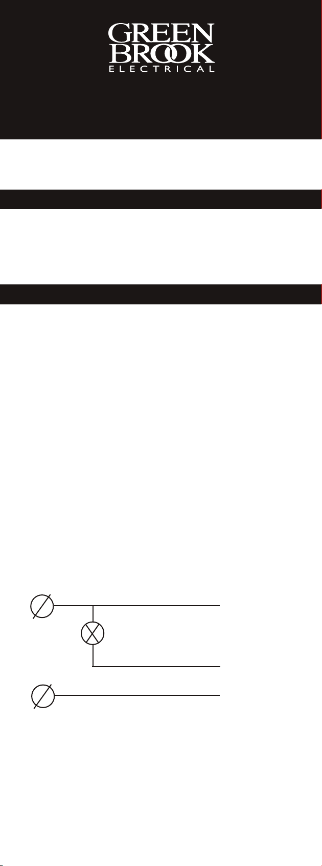
5. Terminate the cable into the NEMA socket observing the
correct connections:-
‘Li’ = LIVE (supply in)
‘Lo’= LOAD (supply out)
‘N’ = Neutral
N (Neutral)
L
Lo (Load)
Li (Live)
6. Place the NEMA socket into the base holder with the
arrow printed on the socket pointing towards north, if north
is located behind the unit or towards the mounting surface
then the arrow should be aligned pointing in the direction of
the best natural light.
7. The base holder has 2 locating pins for the NEMA socket to
fit onto, the NEMA socket should then be secured using the
2 countersunk self tapping screws provided.
Page 2

8. Align the largest of the 3 brass feet marked ‘Neutral’ on the
hotocell head with the largest slot in the NEMA socket,
p
push the photocell head into the NEMA socket and gently
turn clockwise to lock into place.
PERATION & TESTING
O
. The photocell always powers up in the ‘On’ position, if in bright
1
daylight it will switch off within 2 minutes, normal operation will
then resume.
2. To test for correct operation cover the photocell with the
packing box, after a short delay, 15 - 120 seconds, the
photocell will operate and power will be applied to the load.
If tested in bright daylight after a similar delay the photocell
will turn off the power to the load when the packing box is
removed.
COMMON PROBLEMS
The load stays on:-
The photocell is in a shady or dark position or the neutral is not
connected.
The load is flashing, strobing or switching on and off repeatedly
hrough hours of darkness:-
t
The photocell is too close to the light source it is controlling or ‘Li’ &
‘Lo’ are reversed.
Note: These photocells are LED compatible and can run up to
400 watts, the number of light fittings should be limited to no
more than
10 fittings.
TECHNICAL INFORMATION
Type: Electronic Relay Load Switching
Voltage: 230V ~50Hz
Sensor: Photodiode
Light Level: On <20Lux Off >80Lux
Typical Load:
PEC1000:- 2000W Tungsten or 2 x 400W HPS
PEC500:- 1000W Tungsten or 2 x 240W HPS
Operating Temp: -20°C to +80°C
Max Switching Capacity:
PEC1000:- 10A
PEC500:- 5A
Switching Delay: 10 - 15 seconds
Enclosure Material: UV Stabilised Polycarbonate
Power Consumption: <0.25W
IP Rating: IP65
Electrical Life: 6500 cycles
Conforms To: EN 60947-1
PLEASE KEEP THESE INSTRUCTIONS
SAFE FOR FUTURE REFERENCE
or 1800VA
400W Max LED
or 900VA
400W Max LED
EN 61000-3
EN 61000-6
GUARANTEE
Your GreenBrook Photocell Kit
is guaranteed for 1 year from
the date of purchase.
This is in addition to your statutory rights.
WEST ROAD . HARLOW
ESSEX . CM20 2BG . UK
www.greenbrook.co.uk
Issue no: 705125
 Loading...