

Great Planes GPMA1575 User Manual
WAMF GR
SPECIFICATIONS RADIO
2
]
Weight:
Wing
Loading:
3.5– 3.75 lb
[1590-1700 g]
16– 17 oz/sq ft
[49–52 g/dm
Length: 51.5 in
Motor: RimFire .32 (42-50-800)
2
]
[1310mm]
brushless out-runner motor
Wingspan:
50 in
[1270mm]
Wing Area: 505 sq in
[32.6 dm
WARRANTY
Great Planes® Model Manufacturing Co. guarantees this kit to
be free from defects in both material and workmanship at the
date of purchase. This warranty does not cover any component
parts damaged by use or modification. In no case shall Great
Planes’ liability exceed the original cost of the purchased kit.
Further, Great Planes reserves the right to change or modify this
warranty without notice.
In that Great Planes has no control over the final assembly or
material used for final assembly, no liability shall be assumed nor
accepted for any damage resulting from the use by the user of
the final user-assembled product. By the act of using the
user-assembled product, the user accepts all resulting liability.
If the buyer is not prepared to accept the liability associated
with the use of this product, the buyer is advised to return
READ THROUGH THIS MANUAL BEFORE STARTING CONSTRUCTION. IT CONTAINS IMPORTANT
INSTRUCTIONS AND WARNINGS CONCERNING THE ASSEMBLY AND USE OF THIS MODEL.
this kit immediately in new and unused condition to the
place of purchase.
To make a warranty claim send the defective part or item to
Hobby Services at the address below:
Hobby Services
3002 N. Apollo Dr. Suite 1
Champaign IL 61822 USA
Include a letter stating your name, return shipping address, as
much contact information as possible (daytime telephone
number, fax number, e-mail address), a detailed description of
the problem and a photocopy of the purchase receipt. Upon
receipt of the package the problem will be evaluated as quickly
as possible.
4-channel
minimum
w/4 micro servos
and standard
size receiver
Champaign, Illinois
(217) 398-8970, Ext 5
airsupport@greatplanes.com
Entire Contents © Copyright 2009 GPMA1575 Mnl
TABLE OF CONTENTS
INTRODUCTION
INTRODUCTION . . . . . . . . . . . . . . . . . . . . . . . . . . . . . . . .2
AMA. . . . . . . . . . . . . . . . . . . . . . . . . . . . . . . . . . . . . . .2
SAFETY PRECAUTIONS. . . . . . . . . . . . . . . . . . . . . . . . . .3
DECISIONS YOU MUST MAKE. . . . . . . . . . . . . . . . . . . . .3
Radio Equipment . . . . . . . . . . . . . . . . . . . . . . . . . . . . .3
Motor Recommendation. . . . . . . . . . . . . . . . . . . . . . . .3
Propeller. . . . . . . . . . . . . . . . . . . . . . . . . . . . . . . . . . . .4
Batteries & Charger . . . . . . . . . . . . . . . . . . . . . . . . . . .4
ADDITIONAL ITEMS REQUIRED . . . . . . . . . . . . . . . . . . .4
Required Hardware & Accessories . . . . . . . . . . . . . . .4
Adhesives & Building Supplies. . . . . . . . . . . . . . . . . . .4
Optional Supplies & Tools . . . . . . . . . . . . . . . . . . . . . .4
Building Stand . . . . . . . . . . . . . . . . . . . . . . . . . . . . . . .5
IMPORTANT BUILDING NOTES . . . . . . . . . . . . . . . . . . . .5
COMMON ABBREVIATIONS . . . . . . . . . . . . . . . . . . . . . . .5
KIT INSPECTION. . . . . . . . . . . . . . . . . . . . . . . . . . . . . . . .5
KIT CONTENTS. . . . . . . . . . . . . . . . . . . . . . . . . . . . . . . . .6
ORDERING REPLACEMENT PARTS . . . . . . . . . . . . . . . .6
BUILDING INSTRUCTIONS. . . . . . . . . . . . . . . . . . . . . . . .7
Preparations. . . . . . . . . . . . . . . . . . . . . . . . . . . . . . . . .7
ASSEMBLE THE WING . . . . . . . . . . . . . . . . . . . . . . . . . . .7
INSTALL THE HORIZONTAL
STABILIZER & ELEVATORS . . . . . . . . . . . . . . . . . .9
INSTALL THE LANDING GEAR. . . . . . . . . . . . . . . . . . . .11
INSTALL THE TAIL SERVOS & PUSHRODS. . . . . . . . . .12
Aft Tail Servo Installation . . . . . . . . . . . . . . . . . . . . . .16
MOTOR INSTALLATION. . . . . . . . . . . . . . . . . . . . . . . . . .16
FINISH THE MODEL . . . . . . . . . . . . . . . . . . . . . . . . . . . .18
Apply the decals. . . . . . . . . . . . . . . . . . . . . . . . . . . . .18
GET THE MODEL READY TO FLY. . . . . . . . . . . . . . . . . .19
Install and Operate the Motor Battery
(Brushless Only) . . . . . . . . . . . . . . . . . . . . . . . . . .19
Check the Control Directions. . . . . . . . . . . . . . . . . . .19
Set the Control Throws. . . . . . . . . . . . . . . . . . . . . . . .20
Balance the Model (C.G.). . . . . . . . . . . . . . . . . . . . . .20
Balance the Model Laterally. . . . . . . . . . . . . . . . . . . .21
PREFLIGHT . . . . . . . . . . . . . . . . . . . . . . . . . . . . . . . . . . .21
Identify Your Model. . . . . . . . . . . . . . . . . . . . . . . . . . .21
Charge the Batteries . . . . . . . . . . . . . . . . . . . . . . . . .21
Balance Propellers. . . . . . . . . . . . . . . . . . . . . . . . . . .21
Range Check. . . . . . . . . . . . . . . . . . . . . . . . . . . . . . .22
MOTOR SAFETY PRECAUTIONS. . . . . . . . . . . . . . . . . .22
LITHIUM BATTERY HANDLING AND USAGE. . . . . . . . .22
AMA SAFETY CODE (excerpts) . . . . . . . . . . . . . . . . . . .22
General . . . . . . . . . . . . . . . . . . . . . . . . . . . . . . . . . . .22
Radio Control. . . . . . . . . . . . . . . . . . . . . . . . . . . . . . .22
CHECK LIST . . . . . . . . . . . . . . . . . . . . . . . . . . . . . . . . . .23
FLYING. . . . . . . . . . . . . . . . . . . . . . . . . . . . . . . . . . . . . . .23
Takeoff . . . . . . . . . . . . . . . . . . . . . . . . . . . . . . . . . . . .23
Flight . . . . . . . . . . . . . . . . . . . . . . . . . . . . . . . . . . . . .24
Landing . . . . . . . . . . . . . . . . . . . . . . . . . . . . . . . . . . .24
Congratulations on your purchase of the Great Planes
Sequence ARF! The Sequence has been designed to be a
lightweight, precision pattern plane that assembles quickly
and easily. An included pull-pull system provides extreme
accuracy in rudder control. Aft mounting positions are also
provided for the tail servos f or direct pushrod connection. The
best part of the build is the pre-trimmed cowl and pre-installed
cowl ring! Just snap the cowl in place over the fi rewall and
you’re ready to move on! Radio equipment and the battery
pack are easily accessible beneath the magnetically held
canopy hatch that can be removed quickly without tools.
For the latest technical updates or manual corrections to
the Sequence ARF visit the Great Planes web site at www.
greatplanes.com. Open the “Airplanes” link, then select
the Sequence ARF. If there is new technical information or
changes to this model a “tech notice” box will appear in the
upper left corner of the page.
AMA
We urge you to join the AMA (Academy of Model Aeronautics)
and a local R/C club. The AMA is the go verning body of model
aviation and membership is required to fl y at AMA clubs.
Though joining the AMA provides many benefi ts, one of the
primary reasons to join is liability protection. Coverage is not
limited to fl ying at contests or on the club fi eld. It ev en applies
to fl ying at public demonstrations and air shows. Failure to
comply with the Safety Code (excerpts printed in the back of
the manual) may endanger insurance cov erage . Additionally,
training programs and instructors are available at AMA club
sites to help you get started the right way. There are over
2,500 AMA chartered clubs across the countr y. Contact the
AMA at the address or toll-free phone number below:
Academy of Model Aeronautics Ph. (800) 435-9262
5151 East Memorial Drive Fax (765) 741-0057
Muncie, IN 47302-9252
Or via the Internet at:
http://www.modelaircraft.org
IMPORTANT!!!
Two of the most important things you can do to preserve the
radio controlled aircraft hobby are to avoid fl ying near fullscale aircraft and avoid fl ying near or over groups of people.
2

PROTECT YOUR MODEL, YOURSELF
& OTHERS… FOLLOW THESE
IMPORTANT SAFETY PRECAUTIONS
1. Your Sequence ARF should not be considered a toy, but
rather a sophisticated, working model that functions very
much like a full-size airplane. Because of its performance
capabilities, the Sequence ARF, if not assembled and
operated correctly, could possibly cause injury to yourself or
spectators and damage to property.
2. You must assemble the model according to the
instructions. Do not alter or modify the model, as doing
so may result in an unsafe or unfl yable model. In a few
cases the instructions may differ slightly from the photos.
In those instances the written instructions should be
considered as correct.
We, as the kit manuf acturer, provide you with a top quality ,
thoroughly tested kit and instructions, but ultimately the
quality and fl yability of your fi nished model depends
on how you build it; therefore, we cannot in any way
guarantee the performance of your completed model,
and no representations are expressed or implied as to the
performance or safety of your completed model.
Remember: T ake your time and f ollow the instructions to
end up with a well-built model that is straight and true.
DECISIONS YOU MUST MAKE
This is a partial list of items required to fi nish the Sequence
ARF that may require planning or decision making
before starting to build. Order numbers are provided in
parentheses.
3. You must take time to build straight, true and strong.
4. You must use an R/C radio system that is in fi rst-class
condition, and a correctly sized motor and components
throughout the building process.
5. You must correctly install all R/C and other components
so that the model operates correctly on the ground and in
the air.
6. You must check the operation of the model before every
fl ight to insure that all equipment is operating and that the
model has remained structurally sound. Be sure to check
clevises or other connectors often and replace them if they
show any signs of wear or fatigue.
7. If you are not an experienced pilot or have not fl own
this type of model before, we recommend that you get the
assistance of an experienced pilot in your R/C club for
your fi rst fl ights. If you’re not a member of a club, your local
hobby shop has information about clubs in your area whose
membership includes experienced pilots.
8. While this kit has been fl ight tested to exceed normal use,
if the plane will be used for extremely high stress fl ying, such
as racing, or if a motor larger than one in the recommended
range is used, the modeler is responsible for taking steps to
reinforce the high stress points and/or substituting hardware
more suitable for the increased stress.
Radio Equipment
The Sequence ARF requires a minimum 4-channel radio
system with four micro servos such as the Futaba® S3115
micro precision servo. For optimum performance, we
recommend using Futaba S3150 digital micro servos.
In addition, two 12" [305mm] servo extensions are required
for the aileron servos. Two 24" [610mm] servo extensions
are required for the elevator and r udder servos if installing
the servos in the optional aft location. Servo extensions will
not be required for the elev ator and rudder servos if using the
recommended power system and battery. If you are using
a radio system that does not support mixing functions, a
Y-harness will also be required to connect the aileron servos
to the receiver. One 6" [152mm] servo extension is required
for the ESC.
Futaba S3115 Micro Precision Servo (FUTM0415)
❏
OR
Futaba S3150 Slim Digital Servo (FUTM0303)
❏
Plus
Hobbico
❏
Futaba J (HCAM2100)
Futaba Dual Servo Extension 6" J (FUTM4130)
❏
Hobbico Servo Extension 24" Futaba J (HCAM2200)
❏
Hobbico Extension 6" Futaba J (HCAM2000)
❏
®
Extension 12" [152mm]
9. WARNING: The cowl and wheel pants included in this kit
are made of fi berglass, the fi bers of which may cause eye,
skin and respiratory tract irritation. Never blow into a part
to remove fi berglass dust, as the dust will blow back into
your eyes. Always wear safety goggles, a particle mask and
rubber gloves when grinding, drilling and sanding fi berglass
parts. Vacuum the parts and the work area thoroughly after
working with fi berglass parts.
Motor Recommendation
The recommended motor for the Sequence ARF is a
RimFire™ .32 (42-50-800) brushless outrunner motor.
Great Planes RimFire .32 (42-50-800) Out-Runner
❏
Brushless (GPMG4700)
3

If using the recommended brushless motor, a 45A brushless
ESC is required:
Great Planes Silver Series 45A Brushless ESC
❏
5V/2A (GPMM1840)
Adhesives and Building Supplies
This is the list of Adhesives and Building Supplies that are
required to fi nish the Sequence ARF:
Propeller
If you are installing the recommended RimFire brushless
motor, we suggest a 12x6E APC propeller.
APC 12x6 Electric Propeller (APCQ4130)
❏
Batteries and Charger
One 2100mAh 14.8V Lithium Polymer battery pack is
recommended.
Great Planes ElectriFly LiPo 14.8V 2100mAh 20C
❏
Power (GPMP0618)
A cell balancer is required for the LiPo battery pack
listed above:
Great Planes ElectriFly Equinox LiPo Cell Balancer
❏
1-5 (GPMM3160)
A suitable charger is also required. The Great Planes
PolyCharge4™ is designed for LiPo packs only. However, it
is able to charge four LiPo packs simultaneously. The Great
Planes Triton2™ charger will only charge one pack at a time,
but is capable of charging NiCd, NiMH, LiPo, and Pb acid
batteries. Order numbers for both are provided below:
Great Planes PolyCharge4 DC Only 4 Output LiPo
❏
Charger (GPMM3015)
OR
Great Planes ElectriFly Triton2 DC Comp Peak
❏
Charger (GPMM3153)
ADDITIONAL ITEMS REQUIRED
Required Hardware and Accessories
This is the list of hardware and accessories required to
fi nish the Sequence ARF. Order numbers are provided in
parentheses:
Great Planes Velcro Hook & Loop 1x6" (2)
❏
(GPMQ4480)
DuraTrax
❏
®
Servo Tape Wide 1x36" (DTXR1215)
1/2 oz. [15g] Thin Pro
❏
Pro 30-minute epoxy (GPMR6047)
❏
Threadlocker thread locking cement (GPMR6060)
❏
Denatured alcohol (for epoxy clean up)
❏
Drill bits: 1/16" [1.6mm], 5/64" [2mm]
❏
Small metal fi le
❏
#1 Hobby knife (HCAR0105)
❏
#11 blades (5-pack, HCAR0211)
❏
Medium T-pins (100, HCAR5150)
❏
Top Flite
❏
Top Flite Hot Sock iron cover (TOPR2175)
❏
220 grit sandpaper
❏
Panel Line Pen (TOPQ2510)
❏
®
MonoKote® sealing iron (TOPR2100)
™
CA (GPMR6001)
Optional Supplies and Tools
Here is a list of optional tools that will help you build the
Sequence ARF:
1/2 oz. [15g] Medium Pro CA+ (GPMR6007)
❏
1/2 oz. [15g] Thick Pro CA- (GPMR6013)
❏
2 oz. [57g] spray CA activator (GPMR6035)
❏
4 oz. [113g] aerosol CA activator (GPMR6034)
❏
CA applicator tips (HCAR3780)
❏
CA debonder (GPMR6039)
❏
Pro 6-minute epoxy (GPMR6045)
❏
Epoxy brushes 6, (GPMR8060)
❏
Mixing sticks (GPMR8055)
❏
Mixing cups (GPMR8056)
❏
Pliers with wire cutter (HCAR0625)
❏
Rotary tool such as Dremel
❏
Rotary tool reinforced cut-off wheel (GPMR8020)
❏
Servo horn drill (HCAR0698)
❏
Hobby Heat
❏
Precision Magnetic Prop Balancer (TOPQ5700)
❏
AccuThrow
❏
CG Machine™ (GPMR2400)
❏
Hobbico Flexible 18" Ruler Stainless Steel
❏
(HCAR0460)
Top Flite MonoKote trim seal iron (TOPR2200)
❏
Top Flite MonoKote heat gun (TOPR2000)
❏
Hobbico Pin Vise 1/16 Collet w/6 Bits (HCAR0696)
❏
Hobbico 8-Piece Ball Tip Hex L Wrench SAE
❏
(HCAR0520)
Great Planes Clevis Installation Tool (GPMR8030)
❏
™
micro torch II (HCAR0755)
™
Defl ection Gauge (GPMR2405)
4
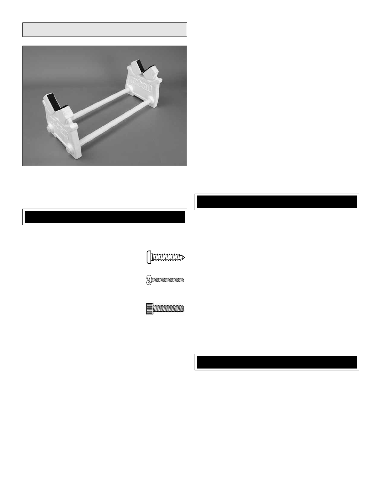
Building Stand
A building stand or cradle comes in handy during the build.
We use the Robart Super Stand II (ROBP1402) for all our
projects in R&D, and it can be seen in pictures throughout
this manual.
patched with additional MonoKote purchased separately.
MonoKote is packaged in six-foot rolls, but some hobby
shops also sell it by the foot. If only a small piece of
MonoKote is needed for a minor patch, perhaps a fellow
modeler would give you some. MonoKote is applied with
a model airplane covering iron, but in an emergency a
regular iron could be used. A roll of MonoK ote includes full
instructions for application. Following are the colors used
on this model and order numbers for six foot rolls.
White TOPQ0204 Orange TOPQ0202
Circus Pink TOPQ0215 Sapphire Blue TOPQ0226
Missle Red TOPQ0201 Sky Blue TOPQ0206
• The stabilizer and wing incidences and engine thrust
angles have been factory-built into this model. However,
some technically-minded modelers may wish to check
these measurements anyway. To view this information
visit the web site at www.greatplanes.com and click on
“Technical Data.” Due to manufacturing tolerances which
will have little or no effect on the way your model will fl y,
please expect slight deviations between your model and
the published values.
COMMON ABBREVIATIONS
IMPORTANT BUILDING NOTES
There are several types of screws used in this kit:
•
Self-tapping or sheet metal screws
are designated by a number and a
length. For example, #6 x 3/4" [19mm].
Machine screws are designated by a
number, threads per inch, and a length.
For example, 4-40 x 3/4" [19mm].
Socket Head Cap Screws (SHCS) are
designated by a number, threads per
inch, and a length. For example, 4-40 x
3/4" [19mm]
• When you see the term test fi t in the instructions, it means
that you should fi rst position the part on the assembly
without using any glue, then slightly modify or custom fi t
the part as necessary for the best fi t.
• Whenever the term glue is written you should rely upon
your experience to decide what type of glue to use. When
a specifi c type of adhesive works best for that step, the
instructions will make a recommendation.
• Whenever just epoxy is specifi ed you may use either
30-minute (or 45-minute) epoxy or 6-minute epoxy. When
30-minute epoxy is specifi ed it is highly recommended that
you use only 30-minute (or 45-minute) epo xy , because you
will need the working time and/or the additional strength.
• Photos and sketches are placed before the step they
refer to . F requently you can study photos in f ollowing steps
to get another view of the same parts.
• The Sequence is factory-covered with Top Flite MonoKote
fi lm. Should repairs ever be required, MonoKote can be
Stab = Horizontal Stabilizer
Fin = Vertical Stabilizer
LE = Leading Edge
TE = Trailing Edge
LG = Landing Gear
Ply = Plywood
" = Inches
mm = Millimeters
SHCS = Socket Head Cap Screw
ESC = Electronic Speed Control
LiPo = Lithium Polymer battery
4S = Four cells in series
mAh = Milliamp Hours (refers to the usable
capacity of a battery)
T o convert inches to millimeters, m ultiply inches b y 25.4
(25.4mm = 1")
KIT INSPECTION
Before starting to build, take an inventory of this kit to make
sure it is complete, and inspect the parts to make sure they
are of acceptable quality . If any parts are missing or are not of
acceptable quality, or if you need assistance with assembly,
contact Product Support. When reporting defective or
missing parts, use the part names exactly as they are written
in the Kit Contents list.
Great Planes Product Support (217) 398-8970, ext. 5
3002 N Apollo Drive, Suite 1 Fax: (217) 398-7721
Champaign, IL 61822
E-mail: airsupport@greatplanes.com
5
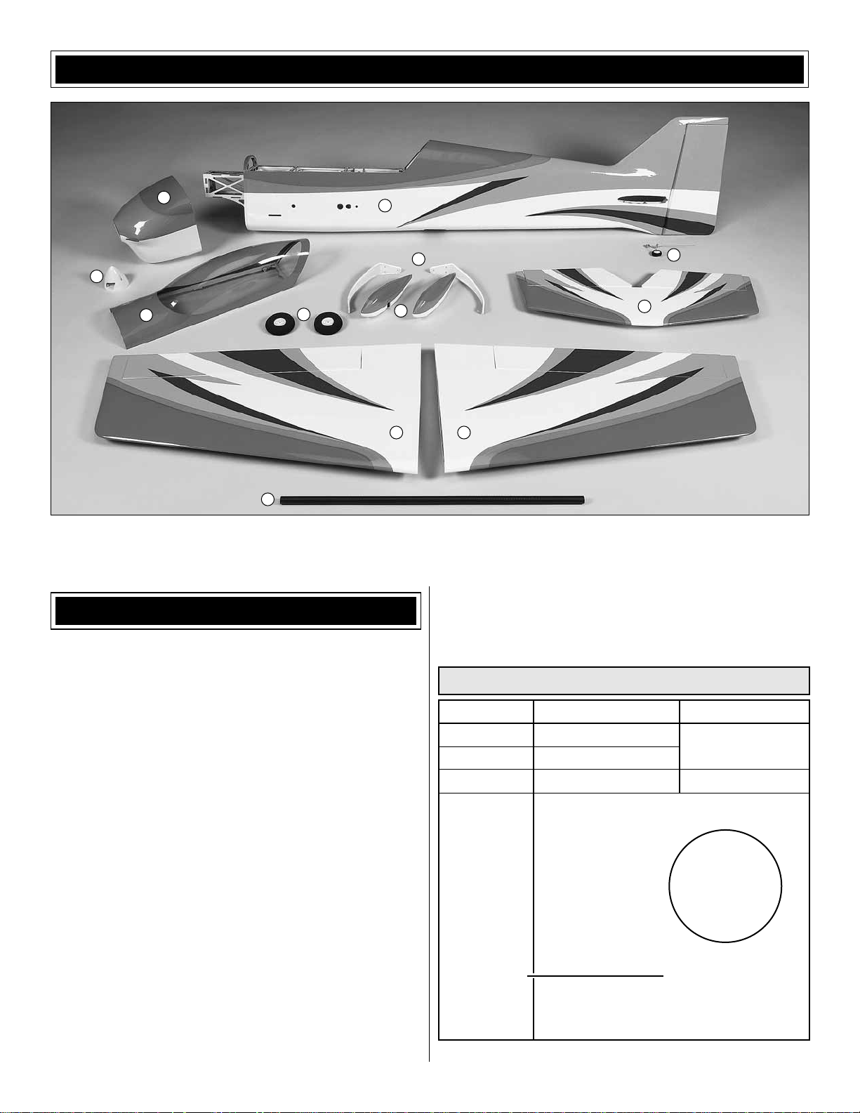
KIT CONTENTS
10
11
9
1. Fuselage
2. Left Wing with Aileron
3. Right Wing with Aileron
8
4
4. Carbon Wing Joiner
5. Horizontal Stabilizer w/ Elevators
6. Main Landing Gear
1
7
ORDERING REPLACEMENT PARTS
Replacement parts for the Great Planes Sequence ARF are
available using the order n umbers in the Replacement Parts
List that follows. The fastest, most economical service can
be provided by your hobby dealer or mail-order company.
To locate a hobby dealer, visit the Hobbico web site at www.
hobbico.com. Choose “Where to Buy” at the bottom of the
menu on the left side of the page. Follow the instructions
provided on the page to locate a U.S., Canadian or
International dealer.
Parts may also be ordered directly from Hobby Services by
calling (217) 398-0007, or via facsimile at (217) 398-7721,
but full retail prices and shipping and handling charges will
apply. Illinois and Nevada residents will also be charged
sales tax. If ordering via fax, include a Visa® or MasterCard®
number and expiration date for payment.
Mail parts orders and payments by personal check to:
Hobby Services
3002 N Apollo Drive, Suite 1
Champaign IL 61822
Be certain to specify the order number exactly as listed in
the Replacement Parts List. Payment by credit card or
personal check only; no C.O.D.
6
23
7. Wheel Pants
8. Main Wheels
9. Canopy Hatch
12
5
10. Cowl
11. Spinner
12. Tail Wheel Assembly
If additional assistance is required for any reason contact
Product Support by e-mail at productsupport@greatplanes.
com, or by telephone at (217) 398-8970.
REPLACEMENT PARTS LIST
Order No. Description
Missing pieces
Instruction manual
Full-size plans
GPMA3369
GPMA3370
GPMA3371
GPMA3372
GPMA3373
GPMA3374
GPMA3375
GPMA3376
GPMA3377
GPMA3328
Wing Set
Fuselage
Tail Set
Land Gear
Wheel Pants
Cowl
Canopy
Wing Tube
Decal Sheet
Tailwheel Assembly
How to purchase
Contact
Product Support
Not available
Contact your
hobby supplier
to purchase
these items
Upgrade Parts
GPMA3378
GPMQ4273
GPMQ4404
CF Landing Gear Sequence ARF
Low Profile Landing Gear Axles 4mm (2)
Nylon Ez Bolts 10-24 (2)
6
BUILDING INSTRUCTIONS
Preparations
1. If y ou hav e not done so already , remo ve the major parts
❏
of the kit from the box and inspect for damage. If any parts
are damaged or missing, contact Product Support at the
address or telephone number listed in the “Kit Inspection”
section on page 5.
2. Carefully remove the tape and separate all the control
❏
surfaces. Use a covering iron with a covering sock on high
heat to tighten the covering if necessary. Apply pressure over
sheeted areas to thoroughly bond the covering to the wood.
ASSEMBLE THE WING
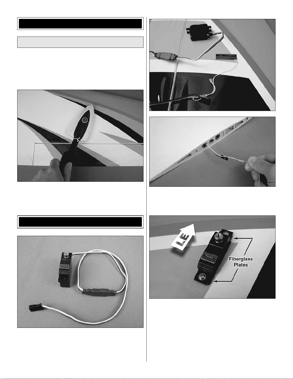
1. Attach a 12" [305mm] servo extension to each aileron
❏
servo. Secure the connections using tape , heat shrink tubing
(not included) or special clips designed for that purpose.
2. Locate the strings taped inside the aileron servo bays
❏
and tie the ends of the strings to the servo extensions. Use
the string to pull the servo leads through the wing ribs.
3. Position the servos in the aileron servo bays in the
❏
orientation shown. Drill 1/16" [1.6mm] holes through the servo
mounting tabs. Thread a servo mounting screw (included with
the servos) into each hole and back it out. Apply a drop of
thin CA to each hole to harden the wood. When the glue has
dried, install the servos using the included black fi berglass
plates and the screws included with the servos. Do not use
the rubber grommets or eyelets included with the servos
because the fl ex allowed by the grommets will reduce the
precision of the control surfaces.
7
Enlarge to
5/64" [2mm]
Cut off
unused
arms
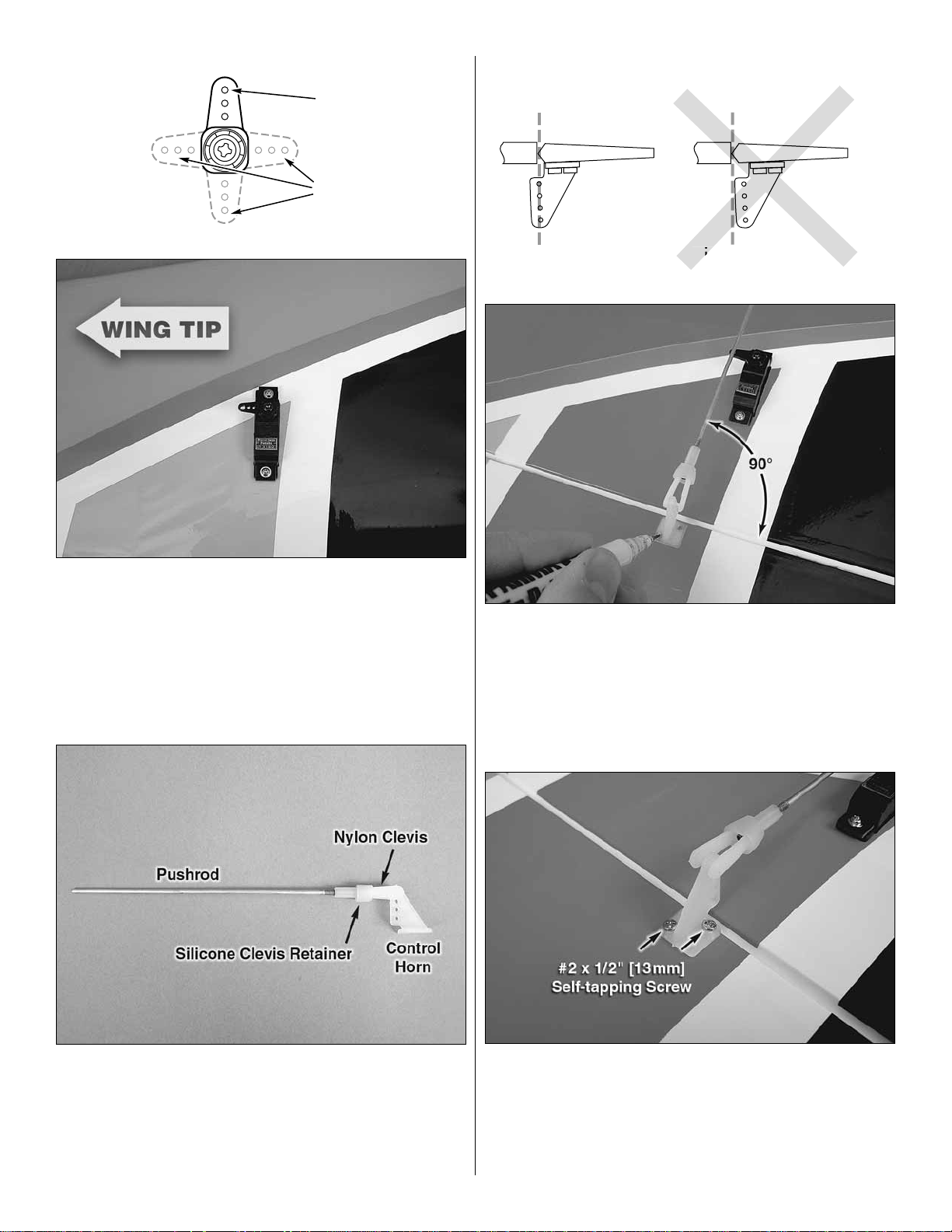
CORRECT INCORRECT
Hinge Line Hinge Line
4. Cut three arms from a four-armed servo arm for each
❏
aileron servo. Enlarge the outer hole of the remaining ar m
with a 5/64" [2mm] drill bit. Center the servos with your r adio
system and install the servo arms to the servos perpendicular
to the servo case as shown with the arms pointing toward
the wing tip. Be sure to reinstall the ser vo arm screws into
the servos (use thread locking compound if the servo has a
metal output spline).
6. Position the control horns over the hardwood blocks
❏
in the ailerons (if you cannot see them, hold the aileron
at a shallow angle in good lighting or use a small pin to
puncture the covering) using the position of the servo arms
as a guide. Align the holes in the control horns directly ov er
the aileron hinge line and mark the location of the control
horn mounting holes.
5. Thread a nylon clevis 20 complete turns onto each 5"
❏
[127mm] pushrod. Slide a silicone clevis retainer onto each
clevis and connect the clevises to the outer holes of two
control horns.
7. Drill 1/16" [1.6mm] holes at the marks you made
❏
through the hardwood blocks. Do not drill all the way through
the aileron! Apply a couple drops of thin CA glue to each
hole to harden the wood surrounding the holes. When the
glue has dried, install the control horns onto the ailerons
using four #2 x 1/2" [13mm] self-tapping screws.
8
 Loading...