

Page 1
INSTRUCTION MANUAL
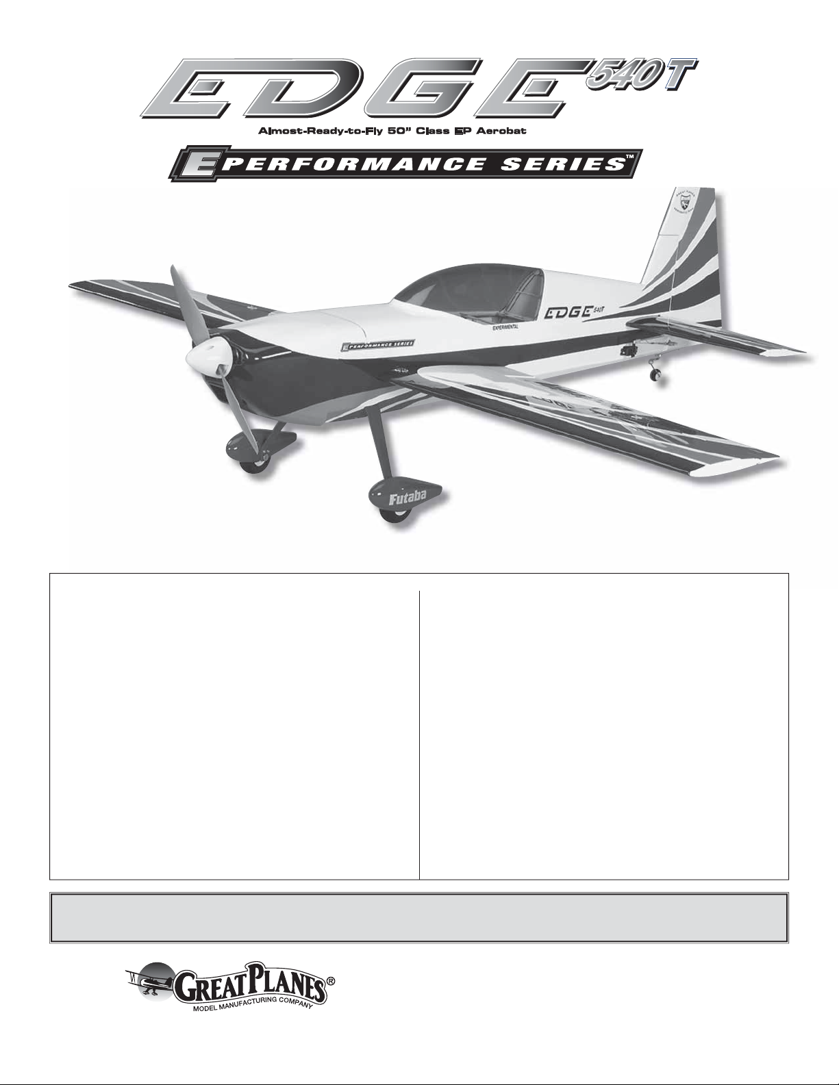
Wingspan: 49.5 in [1260mm]
Wing Area: 490 in2 [31.6dm2]
Weight: 3.25 – 3.5 lb [1470 – 1590g]
Wing Loading: 15.0 – 16.0 oz/ft2 [46 – 49g/dm2]
Length: 48 in [1220mm]
Radio: 4-channel minimum, 5-channel computer radio with
mixing capabilities (for separate ailerons)
Motor: RimFire™ 42-50-800 out-runner
WARRANTY
Great Planes® Model Manufacturing Co. guarantees this kit to be
free from defects in both material and workmanship at the date
of purchase. This warranty does not cover any component parts
damaged by use or modifi cation. In no case shall Great Planes’
liability exceed the original cost of the purchased kit. Further,
Great Planes reserves the right to change or modify this warranty
without notice.
In that Great Planes has no control over the fi nal assembly or
material used for fi nal assembly, no liability shall be assumed nor
accepted for any damage resulting from the use by the user of
the fi nal user-assembled product. By the act of using the userassembled product, the user accepts all resulting liability.
If the buyer is not prepared to accept the liability associated
with the use of this product, the b uyer is advised to return this
kit immediately in new and unused condition to the place of
purchase.
To make a warranty claim send the defective part or item to Hobby
Services at the address below:
Hobby Services
3002 N. Apollo Dr., Suite 1
Champaign, IL 61822 USA
Include a letter stating your name, return shipping address, as
much contact information as possible (daytime telephone n umber,
fax number, e-mail address), a detailed description of the problem
and a photocopy of the purchase receipt. Upon receipt of the
package the problem will be evaluated as quickly as possible.
READ THROUGH THIS MANU AL BEFORE ST ARTING CONSTR UCTION. IT CONT AINS IMPOR T ANT INSTRUCTIONS
AND WARNINGS CONCERNING THE ASSEMBLY AND USE OF THIS MODEL.
Champaign, Illinois
(217) 398-8970, Ext 5
airsupport@greatplanes.com
Entire Contents © Copyright 2008 GPMA1572MNL V1.0
Page 2
TABLE OF CONTENTS
INTRODUCTION
INTRODUCTION ...............................................................2
AMA ..................................................................................2
SAFETY PRECAUTIONS .................................................3
DECISIONS YOU MUST MAKE ........................................3
Radio Equipment ..........................................................3
Transmitter ...................................................................3
Receiver .......................................................................3
Servos ..........................................................................3
Connectors ...................................................................3
Motor Recommendations .............................................4
ESC (electronic speed control) ....................................4
Flight Battery ................................................................4
ADDITIONAL ITEMS REQUIRED ....................................4
Required Adhesives & Building Supplies .....................4
Optional Supplies & Tools ............................................4
IMPORTANT BUILDING NOTES ......................................4
ORDERING REPLACEMENT PARTS ..............................5
KIT INSPECTION ..............................................................6
KIT CONTENTS ................................................................6
PREPARATIONS ...............................................................7
ASSEMBLE THE WINGS ..................................................7
Install the Aileron Servo & Pushrods ............................8
ASSEMBLE THE FUSELA GE ..........................................8
Install the Main Landing Gear ......................................9
Install the Tail Gear .....................................................10
Install the Stabilizer ....................................................11
Install the Elevators Hinges ........................................12
Install the Elevators ....................................................12
Install the Motor ..........................................................12
INSTALL THE RADIO SYSTEM .....................................12
Install the Elevator Servo ...........................................12
Install the Rudder Servo .............................................13
Rudder Pull-Pull Installation .......................................13
Rudder Servo Installation in the Tail ...........................15
Apply the Decals ........................................................16
GET THE MODEL READY TO FLY .................................16
Check the Control Directions .....................................16
Set the Control Throws ...............................................17
FINISH THE MODEL .......................................................18
Balance the Model (C.G.) ...........................................18
Balance the Model Laterally .......................................19
PREFLIGHT ....................................................................19
Identify Your Model .....................................................19
Charge the Batteries ..................................................19
Balance Propellers .....................................................19
Range Check .............................................................19
MOTOR SAFETY PRECAUTIONS .................................19
AMA SAFETY CODE (EXCERPTS) ...............................20
CHECK LIST ...................................................................20
FLYING ............................................................................21
Takeoff ........................................................................21
Flight ..........................................................................21
Landing ......................................................................22
3D FLYING ......................................................................22
The full-scale Zivko Edge 540T is a great two seat, competition
aerobatic trainer. Great Planes has taken the best qualities of
the full-scale Edge 540T and reduced it down to a lightweight,
50" electric powered ARF. The Great Planes Edge 540T EP
ARF fl ies much like the giant-size Edge’s, but in a much less
expensive pac kage. Now you can practice f or IMAC competition
without risking your larger, more e xpensive planes.
For the latest technical updates or manual corrections to
the Edge 540T EP ARF visit the Great Planes web site at
www.greatplanes.com. Open the “Airplanes” link, then
select the “Edge 540T EP” ARF. If there is new technical
information or changes to this model a “tech notice” box will
appear in the upper left corner of the page.
AMA
We urge you to join the AMA (Academy of Model Aeronautics)
and a local R/C club. The AMA is the go verning body of model
aviation and membership is required to fl y at AMA clubs.
Though joining the AMA provides many benefi ts, one of the
primary reasons to join is liability protection. Coverage is not
limited to fl ying at contests or on the club fi eld. It ev en applies
to fl ying at public demonstrations and air shows. Failure to
comply with the Safety Code (excerpts printed in the back of
the manual) may endanger insurance cov erage . Additionally,
training programs and instructors are available at AMA club
sites to help you get started the right way. There are over
2,500 AMA chartered clubs across the countr y. Contact the
AMA at the address or toll-free phone number below.
Academy of Model Aeronautics
5151 East Memorial Drive
Muncie, IN 47302-9252
Tele. (800) 435-9262
Fax (765) 741-0057
Or via the Internet at:
http://www.modelaircraft.org
IMPORTANT!!! Two of the most important things you can do
to preserve the radio controlled aircraft hobby are to avoid
fl ying near full-scale aircraft and avoid fl ying near or over
groups of people.
2
Page 3

PROTECT YOUR MODEL, Y OURSELF
& OTHERS....FOLLOW THESE
IMPORTANT SAFETY PRECAUTIONS
1. Your Edge 540T EP ARF should not be considered a toy,
but rather a sophisticated, working model that functions very
much like a full-size airplane. Because of its performance
capabilities, the Edge 540T EP ARF, if not assembled and
operated correctly, could possibly cause injury to yourself or
spectators and damage to property.
2. Y ou must assemble the model according to the instructions.
Do not alter or modify the model, as doing so may result in an
unsafe or unfl y able model. In a f e w cases the instructions may
differ slightly from the photos. In those instances the written
instructions should be considered as correct.
DECISIONS YOU MUST MAKE
This is a partial list of items required to fi nish the Edge 540T
EP ARF that may require planning or decision making before
starting to build.
Radio Equipment
A 4-channel radio system with four micro servos and micro
receiver are required for this plane. The servos and receiver
shown in the manual are Futaba® S3115 Micro Precision
Servo and the Futaba R146iP PCM receiver. For more
precision, the Futaba S3150 Slim Digital Servos work great.
3. You must take time to build straight, true and strong.
4. You must use an R/C radio system that is in fi rst-class
condition, and a correctly sized motor and components
(wheels, etc.) throughout the building process.
5. You must correctly install all R/C and other components
so that the model operates correctly on the ground and in
the air.
6. You must check the operation of the model before every
fl ight to insure that all equipment is operating and that the
model has remained structurally sound. Be sure to check
clevises or other connectors often and replace them if they
show any signs of wear or fatigue.
7. If you are not an experienced pilot or have not fl own
this type of model before, we recommend that you get the
assistance of an experienced pilot in your R/C club for
your fi rst fl ights. If you’re not a member of a club, your local
hobby shop has information about clubs in your area whose
membership includes experienced pilots.
8. WARNING: The cowl and wheel pants included in this kit
are made of fi berglass, the fi bers of which may cause eye,
skin and respiratory tract irritation. Never blow into a part
(wheel pant, cowl) to remove fi berglass dust, as the dust
will blow back into your eyes. Always wear safety goggles, a
particle mask and rubber gloves when grinding, drilling and
sanding fi berglass parts. Vacuum the parts and the work
area thoroughly after working with fi berglass parts.
Transmitter
❏ 4-channel radio (minimum)
or
❏ 5-channel computer radio with mixing capabilities
(for separate ailerons).
Receiver
❏ Futaba 4 to 6 channel R146iP PCM receiver (FUTL0601)
❏ Futaba FM Single Conversion Short Crystal (Low Band
(11 to 35) – FUTL62**, High Band (36 to 60) – FUTL63**)
Servos
❏ (4) Futaba S3115 Micro Precision Servos (FUTM0415)
(38.9 oz-in [2.8 kg-cm] of torque)
or
❏ (4) Futaba S3150 Slim Digital Servos (FUTM0303)
(51.4 oz-in [3.7 kg-cm] of torque)
For 3D rudder throws a 2" [50.8mm] double-sided servo arm
may be required (GPMM1155)
Connectors
We, as the kit manuf acturer, provide you with a top quality ,
thoroughly tested kit and instructions, but ultimately the
quality and fl yability of your fi nished model depends
on how you build it; therefore, we cannot in any way
guarantee the performance of your completed model,
and no representations are expressed or implied as to the
performance or safety of your completed model.
Remember: Take y our time and follo w the instructions to
end up with a well-built model that is straight and true.
❏ (1) “Y” harness (FUTM4135)
❏ (2) 16" extensions (FUTM3955)
❏ (2) 12" extensions (HCAM2100)
3
Page 4

Motor Recommendations
The Edge 540T EP ARF comes with a mounting box for the
Great Planes RimFire
motor has been tested with this plane and works well.
™
brushless out-runner motor. The
❏ Great Planes RimFire 42-50-800 Brushless Out-runner
Motor (GPMG4700)
ESC (electronic speed control)
A brushless ESC (electronic speed control) is required for the
recommended motor set-up. We recommend using the Great
Planes Silver Series SS-45A Brushless ESC (GPMM1840).
If you will be using the 4S LiP o setup for 3D fl ying, a voltage
regulator m ust be used with this ESC. If a voltage regulator
is not used the ESC may be damaged.
Flight Battery
We recommend two different battery and prop setups
depending on the type of fl ying you prefer to do. For basic
sport fl ying we recommend the Great Planes Pow er Series™
LiPo 2100mAh 11.1V, 3200mAh 11.1V battery or Flight
Power 2170mAh 11.1V and 2500mAh 11.1V with an APC
13" x 8E propeller.
For all out 3D type fl ying we recommend the Great Planes
Power Series LiPo 2100mAh 14.8V or FlightPower 2170mAh
14.8V battery with an APC 12" x 6E propeller. A voltage
regulator will also be required to power the receiver . Be sure to
follow the ESC instructions for using a separ ate power source
(voltage regulator or receiver battery) for the receiv er.
When charging the batteries we highly recommend using a
Great Planes Equinox™ LiPo Cell Balancer (GPMM3160).
Sport Setup:
❏ Great Planes Power Series LiPo 2100mAh 11.1V 20C
discharge w/balance plug (GPMP0617)
❏ Great Planes Power Series LiPo 3200mAh 11.1V 20C
discharge w/balance plug (GPMP0623)
❏ FlightPower EVO25 LiPo 2170mAh 11.1V
25C (FPWP0327)
❏ FlightPower EVO25 LiPo 2500mAh 11.1V
25C (FPWP0333)
❏ APC 13" x 8E Propeller (APCQ3080)
3D Setup:
❏ APC 12" x 6E Propeller (APCQ4130)
❏ ElectriFly Voltage Regulator (GPMM1920)
❏ Great Planes Parallel ESC Adapter Deans Ultra
Connector (GPMM3141)
ADDITIONAL ITEMS REQUIRED
Required Adhesives & Building Supplies
This is the list of adhesives and building supplies required to fi nish
the Edge 540T EP. Order numbers are provided in parentheses.
❏ 1/2 oz. [15g] Thin Pro
™
CA (GPMR6001)
❏ 1/2 oz. [15g] Medium Pro CA+ (GPMR6007)
❏ Pro 30-minute epoxy (GPMR6047)
❏ Denatured alcohol (for epoxy clean up)
❏ Drill bits: 1/16" [1.6mm], 3/32" [2.4mm], 9/64" [3.6mm],
5/32" [4mm], 7/32" [5.6mm],
❏ #1 Hobby knife (HCAR0105)
❏ #11 Blades (5-pack, HCAR0211)
❏ Small T-pins (100, HCAR5100)
❏ Non-elastic monofi lament or Kevlar
(for stabilizer alignment)
Optional Supplies & Tools
Here is a list of optional tools mentioned in the manual that
will help you build the Edge 540T EP ARF.
®
fi shing line
❏ 2 oz. [57g] Spray CA activator (GPMR6035)
❏ CA applicator tips (HCAR3780)
❏ CA debonder (GPMR6039)
❏ Mixing sticks (50, GPMR8055)
❏ Mixing cups (GPMR8056)
❏ Threadlocker threadlocking cement (GPMR6060)
❏ AccuThrow
❏ C.G. Machine
❏ 21st Century
™
Defl ection Gauge (GPMR2405)
™
(GPMR2400)
®
sealing iron [COCR2700]
❏ 21st Century iron cover [COVR2702]
IMPORTANT BUILDING NOTES
• There are two types of screws used in this kit:
• Sheet Metal Screws are designated by a number and
a length. For example 2 x 12mm.
❏ Great Planes Power Series LiPo 2100mAh 14.8V 20C
discharge w/balance plug (GPMP0618)
❏ FlightPower EVO25 LiPo 2170mAh 14.8V
25C (FPWP0328)
The screw has a diameter of 2mm and a length of 12mm.
• Machine screws are designated by a number, threads
per inch, and a length. For example 4-40 x 3/4" [19mm]
4
Page 5

ORDERING REPLACEMENT PARTS
This is a number four screw that is 3/4" [19mm] long
with forty threads per inch.
• Socket Head Cap Screws (SHCS) are designated by
a number, threads per inch, and a length. For example
4-40 x 3/4" [19mm].
This is a 4-40 SHCS that is 3/4" [19mm] long with forty
threads per inch.
• When you see the term test fi t in the instructions,
it means that you should fi rst position the part on the
assembly without using any glue, then slightly modify
or custom fi t the part as necessary for the best fi t.
• Whenever the term glue is written you should rely upon
your experience to decide what type of glue to use. When
a specifi c type of adhesive works best for that step, the
instructions will make a recommendation.
• We recommend 30-minute epoxy only, because you will
need the working time or the additional strength.
• Photos and sketches are placed before the step they
refer to. Frequently you can study photos in following
steps to get another view of the same parts.
• The Edge 540T EP ARF is factory-covered with Top
Flite® MonoKote® fi lm. Should repairs ever be required,
MonoKote can be patched with additional MonoKote
purchased separately. MonoKote is packaged in six-foot
rolls, but some hobby shops also sell it by the foot. If
only a small piece of MonoKote is needed for a minor
patch, perhaps a fellow modeler would give you some.
MonoKote is applied with a model airplane covering iron,
but in an emergency a regular iron could be used. A roll
of MonoKote includes full instructions for application.
Following are the colors used on this model and order
numbers for six foot rolls.
White – TOPQ0204
Sapphire Blue – TOPQ0226
Medium Purple – TOPQ0225
Sky Blue – TOPQ0206
Royal Blue – TOPQ0221
Replacement parts for the Great Planes Edge 540T EP ARF
are available using the order numbers in the Replacement
Parts List that follows. The fastest, most economical service
can be provided by your hobby dealer or mail-order company.
To locate a hobby dealer, visit the Hobbico web site at www.
hobbico.com. Choose “Where to Buy” at the bottom of the
menu on the left side of the page. Follow the instructions
provided on the page to locate a U.S., Canadian or
International dealer.
Parts may also be ordered directly from Hobby Services by
calling (217) 398-0007, or via facsimile at (217) 398-7721,
but full retail prices and shipping and handling charges will
apply. Illinois and Nevada residents will also be charged
®
sales tax. If ordering via fax, include a Visa
or MasterCard®
number and expiration date for payment.
Mail parts orders and payments by personal check to:
Hobby Services
3002 N. Apollo Drive, Suite 1
Champaign, IL 61822
Be certain to specify the order number exactly as listed in
the Replacement Parts List. Payment by credit card or
personal check only; no C.O.D.
If additional assistance is required for any reason contact Product
Support by e-mail at productsupport@greatplanes.com,
or by telephone at (217) 398-8970.
Replacement Parts List
Description How to Purchase
Missing pieces Contact Product Support
Instruction manual Contact Product Support
Full-size plans Not available
Contact your hobby supplier for the following parts:
GPMA3310 Wing Set
GPMA3311 Fuselage Set
GPMA3312 Tail Set
GPMA3313 Landing Gear
GPMA3314 Wheel Pants (2)
GPMA3315 Tail Wheel Assembly
GPMA3316 Cowl w/Cowl Ring
GPMA3317 Canopy Hatch
GPMA3318 Carbon Fiber Wing Tube
GPMA3321 Decal Sheet
GPMQ4404 10-24 Nylon EZ Bolts (2)
GPMQ4273 4mm Low Profi le Landing Gear Axles (2)
Performance Upgrade Parts
GPMA3319 Carbon Fiber Landing Gear
GPMA3320 Carbon Fiber Wheel Pants (2)
5
Page 6
KIT INSPECTION
KIT INSPECTION
KIT CONTENTS
Before starting to build, take an inventory of this kit to make sure it is complete and inspect the parts to make sure they
are of acceptable quality. If any parts are missing or are not of acceptable quality, or if you need assistance with assembly,
contact Product Support. When reporting defective or missing parts, use the part names exactly as they are written in
the Kit Contents list.
Great Planes Product Support:
3002 N Apollo Drive, Suite 1
Champaign, IL 61822
Telephone: (217) 398-8970, ext. 5
Fax: (217) 398-7721
E-mail: airsupport@greatplanes.com
KIT CONTENTS
2
1
3
4
5
7
5
6
7
11
13
9 9
12
8
10
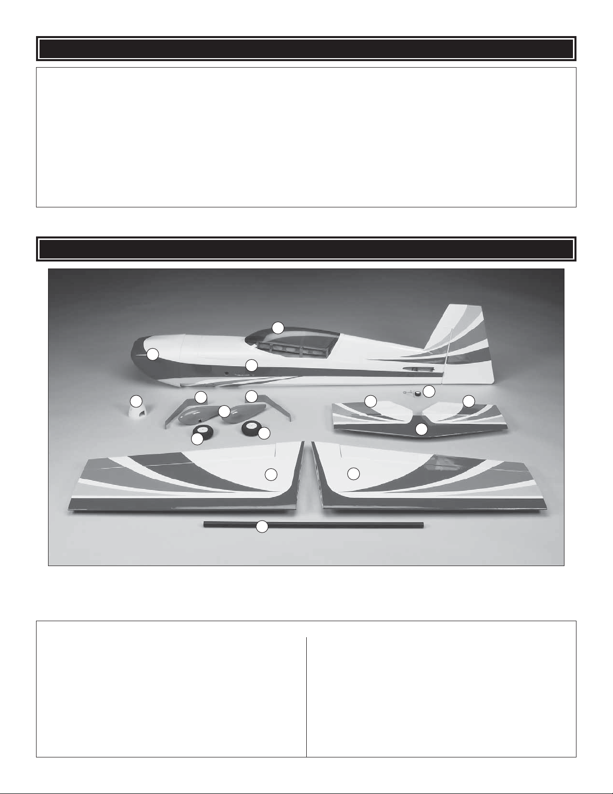
Kit Contents
1 Cowl
2 Canopy
3 Fuselage
4 Spinner
5 Main Landing Gear (L&R)
6 Wheel Pants (L&R)
7 Main Wheels (2)
8 Tail Gear Assembly
9 Elevator Halves (L&R)
10 Horizontal Stabilizer
11 Right Wing Panel w/Aileron
12 Left Wing Panel w/Aileron
13 Carbon Fiber Wing Tube
6
Page 7
PREPARATIONS
❏ 1. If you have not done so already, remove the major parts
of the kit from the box and inspect for damage. If any parts
are damaged or missing, contact Product Support at the
address or telephone number listed in the “Kit Inspection”
section on page 6.
❏ 2. Remove the tape and separate the elevators from the
stab. Use a covering iron with a covering sock on medium/
high heat to tighten the covering if necessary . Apply pressure
over sheeted areas to thoroughly bond the covering to the
wood. Caution: The Edge 540T EP was designed to be
strong where needed, but light weight for excellent fl ight
performance. Care must be taken when assembling the
plane to avoid damage.
❏ ❏ 3. Tie the string to the servo e xtension. Pull the string and
the servo lead through the wing. Untie the string from the lead.
ASSEMBLE THE WINGS
Install the Ailerons Servos & Pushrods
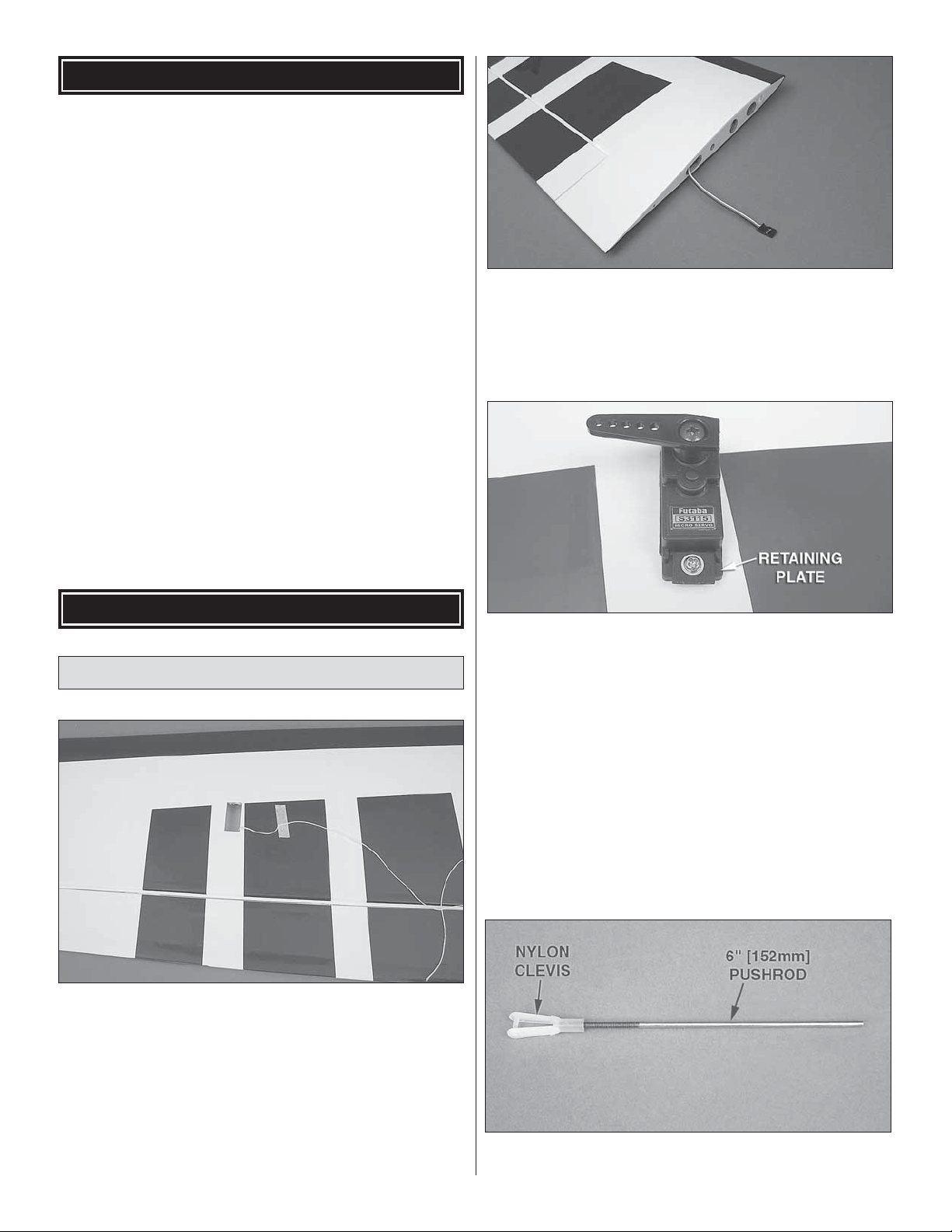
❏ ❏ 1. Inside the servo bay a string is taped. Carefully
remove the string from the servo bay and tape it to the
outside of the wing to prevent it from dropping back into the
wing. Test fi t your aileron servo in the servo ba y. Enlarge the
opening if required.
❏ ❏ 4. Install the servo into the servo opening. Drill through
the servo mounting holes with a 1/16" [1.6mm] drill bit.
Remove the servo from the servo opening. Install and then
remove a servo mounting screw into each of the holes you
have drilled. Apply a drop of thin CA into the holes to harden
the threads. Once the glue has cured install the servo into
the servo opening using the servo screws provided with the
servo and the 2 x 7 x 9mm servo retaining plates. If your
servo uses two screws at each end, do not use the retaining
plates. Center the servo and then install a servo arm as
shown. The arm should be pointing towards the wingtip.
❏ ❏ 2. Install a 12" [305mm] servo e xtension onto the servo
lead. Secure the extension to the lead with tape, a piece of
heat-shrink tubing or some other method to keep them from
coming unplugged.
❏ ❏ 5. Thread a nylon clevis, 20 turns, onto a 6" [152mm]
wire pushrod.
7
7
Page 8
HINGE LINE
CORRECT INCORRECT
❏ ❏ 6. Cut the control horn and mounting plate apart. Attach
the clevis in the outer hole of a nylon control horn. Place the
control horn in line with the hole 3/4" [19mm] from the center
of the servo arm. When positioned properly the control horn
will rest on a hardwood plate in the aileron. Mark the location
of the mounting holes onto the aileron. Drill a 3/32" [2.4mm]
hole on the marks, drilling through the plywood plate and the
top of the aileron.
pushrod where it crosses the aileron servo arm. Make a 90°
bend at the mark. Cut the pushrod 3/8" [9.5mm] past the
bend. Attach the pushrod to the aileron servo arm with a
nylon FasLink.
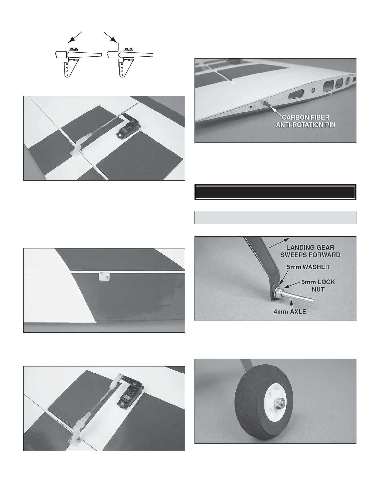
❏ ❏ 9. Glue the carbon fi ber anti rotation pin in the hole as
shown. The pin should protrude approximately 1/4" [6.4mm].
❏ 10. Repeat steps 1 to 9 for the left wing panel.
ASSEMBLE THE FUSELAGE
Install the Main Landing Gear
❏ ❏ 7. Insert two 2-56 x 5/8" [16mm] machine screws
through the control horn and aileron. Secure the control horn
to the aileron with the nylon control horn backplate.
❏ ❏ 8. Slide a silicone clevis retainer over the clevis. With
the aileron servo and the aileron centered, mark the aileron
❏ ❏ 1. Insert a 4mm axle through the right main landing
gear. Secure the axle to the landing gear with a 5mm fl at
washer and 5mm lock nut. Note: The front of the main
landing gear sweeps forward.
❏ ❏ 2. Install two 5mm fl at washers on the axle, then the
foam main wheel, followed by a 4.2mm wheel collar. Secure
the wheel collar on the axle with 6-32 set screw. Mark the
8
8
Page 9

location where the set screw tightens on the axle and use a
metal cutting fi le to fi le a fl at spot on the axle. Apply a drop of
threadlocker on the set screw and reinstall the wheel collar
on the axle.
❏ ❏ 3. Position the right wheel pant over the wheel and
secure it to the main landing gear with two 2-56 x 3/8" [9.5mm]
machine screws, 2mm fl at washers and 2mm lock washers.
❏ 1. Glue the nylon tail gear bushing in the hole in the aft
bottom of the fuselage.
❏ ❏ 4. Attach the main landing gear to the fuselage with
three 4-40 x 1/2" [12.7mm] SHCS, 3mm lock washers and
3mm fl at washers.
❏ 5. Repeat steps 1 to 4 for the left main landing gear.
Install the Tail Gear
❏ 2. Insert the tail gear wire through the aluminum tail gear
bracket. Inser t the tail gear wire and bracket in the tail gear
bushing. With the tail gear bracket aligned with the bottom
of the fuselage, mark and drill a 1/16" [1.6mm] pilot hole at
both tail gear bracket mounting hole locations. Secure the
tail gear bracket to the fuselage with two 2 x 12mm sheet
metal screws.
❏ 3. Thread a 4-40 set screw into the 2.5mm wheel collar.
Remove the tail gear wire from the tail gear bracket and
position the 2.5mm wheel collar under the bracket. Slide the
9
Page 10

nylon tail gear post onto the thin tail gear wire. Insert the tail
gear wire through the aluminum tail gear bracket and wheel
collar while inserting the tail gear post in the bottom of the
rudder. Tighten the set scre w in the wheel collar and glue the
tail gear post in the rudder with thin CA.
❏ 4. Install the tail wheel on the tail gear wire and press the
silicone retainer on the tail gear wire to secure the tail wheel.
❏ 2. Center the horizontal stabilizer in the slot in the fuselage.
Stand back and look at the stab in relation to the wing. The
stab should be parallel with the wing. If not, sand the stab
saddle until the stab and wings are aligned.
Install the Stabilizer
❏ 3. Measure the distance from the tip of the stab to the
center of the fuselage. Adjust the position of the stab until
they are equal. The stringer is centered in the front of the
fuselage.
❏ 1. Center the wing tube in the fuselage. Slide the wing
halves onto the wing tube and secure the wing halves to
the fuselage with the nylon 10-24 thumb screws. Be careful
putting pressure on the wing and fuselage. The wings may
be tight the fi rst time they are slid on the tube.
❏ 4. Using a fi ne-point felt-tip pen, mark the outline of the
fuselage on the top and the bottom of the stab.
❏ 5. Cut the covering on the top and bottom of the stab
inside the line you have drawn. Use care to cut only into the
covering and not into the wood.
10
Page 11

HOW TO CUT COVERING FROM BALSA
Use a soldering iron to cut the covering from the area
beneath the wing bolt plate. The tip of the soldering iron
doesn’t have to be sharp, but a fi ne tip does work best.
Allow the iron to heat fully.
Use a straightedge to guide the soldering iron at a rate
that will just melt the covering and not burn into the wood.
The hotter the soldering iron, the faster it must travel to
melt a fi ne cut. Peel off the covering.
30-minute epoxy to the wood, top and bottom. Slide the stab
through the fuselage so that approximately 1/2" [12.7mm]
of bare wood is showing on the other side and apply epoxy
to the wood. Now align the stab, remove the masking tape
and wipe off any excess epoxy from the stab and fuselage.
Recheck that the stab is still aligned.
You can now remove the wings and continue with the
assembly of the fuselage.
Install the Elevator Hinges
❏ ❏ 1. Drill a 3/32" [2.4mm] hole, 1/2" [12.7mm] deep in the
center of each hinge slot to allow the CA to “wick” in. Followup with a #11 blade to clean out the slots. Hint: If you have
one, use a high-speed rotary tool to drill the holes.
❏ 6. Wipe away the lines you drew. Insert the elevator
joiner wire in the notch at the back of the stab saddle.
Use epoxy to glue the stab in place, being careful that the
stab is properly aligned.
Tip: Place a piece of masking tape on the top and bottom of
the stabilizer, just outside the cut covering. Insert the stab in
the fuselage so that part of the bare wood is showing. Apply
❏ ❏ 2. Use a sharp #11 blade to cut a strip of cov ering from
the hinge slots in the wing and aileron.
1" [25mm]
3/4" [19mm]
Trim the Corners
❏ ❏ 3. Cut six 3/4" x 1" [19 x 25mm] hinges from a CA
hinge strip. Snip off the corners so they go in easier. Inser t
three hinges in each elevator.
11
Page 12

❏ ❏ 4. Test fi t the ele vators to the stab with the hinges . If the
hinges don’t remain centered, stick a pin through the middle
of the hinge to hold it in position.
Install the Elevators
❏ 1. Install the RimFire motor using four 4-40 x 1/2" [12.7mm]
SHCS, four 3mm lock washers and four 3mm fl at washers.
Before installing, apply a drop of threadlock er to the threads of
the SHCS.
❏ 2. Connect the ESC to the motor . The ESC can be attached
to the side of the motor box with hook and loop material.
❏ 1. Install the elevators onto the stab with the elevator
joiner wire in each elevator half. Check that both elevator
halves are aligned. If not, remove the elevators and while
holding one leg of the elevator joiner wire, slightly bend the
other. Reinstall the elevator halves and check again.
❏ 2. Coat the inside of the two elevator joiner wire holes and
the ends of the elevator joiner wire with epo xy. Install the tw o
elevator halves, remove the pins and glue the hinges with
thin CA.
Install the Motor
The Edge 540T EP has been designed to use the Great
Planes RimFire 42-50-800 Out-runner Brushless motor.
If you will be installing a different motor, you may need to
modify the plywood motor box.
❏ 3. Use hook and loop material to mount the receiver in the
fuselage. The antenna can be routed out the bottom of the
fuselage and taped to the covering.
INSTALL THE RADIO SYSTEM
Install the Elevator Servo
❏ 1. Cut the covering away from the lower opening on the
left side, in the rear of the fuselage for the elevator servo.
12
Page 13

❏ 2. Install a 16" [406mm] servo extension to the elevator
servo. Secure the extension to the lead with tape, a piece
of heat-shrink tubing some other method to keep them from
coming unplugged.
❏ 5. Slide a silicone clevis retainer over the clevis. With the
elevator servo and the elevator centered, mark the elevator
pushrod where it crosses the elevator servo arm. Make a
90° bend at the mark. Cut the pushrod 3/8" [9.5mm] past the
bend. Attach the pushrod to the elevator ser vo arm with a
nylon FasLink.
Install the Rudder Servo
❏ 3. Install the elevator servo into the servo openings. Drill
through the servo mounting holes with a 1/16" [1.6mm] drill
bit. Remove the servo from the servo opening. Install and
then remove a servo mounting screw into each of the holes
you have drilled. Apply a drop of thin CA into the holes to
harden the threads. Once the glue has hardened install the
servo into the servo opening using the 2 x 7 x 9mm servo
retaining plates. Center the servo and then install a servo
arm with a hole 3/4" [19mm] from the center.
Now is the time you need to decide on which rudder control
method you are going to use. Unless you are installing a
heavy motor , we recommend that you use the pull-pull system
to keep the weight out of the tail. To help you decide you can
install the wing, cowl and canopy. Mark the C.G. location on
the wing (shown on page 18). Then, place the plane on a C .G.
stand and position the fl ight battery in the middle of the battery
tray. If the plane is slightly tail heavy, we recommend that the
rudder pull-pull system be installed. If the plane is nose heavy,
the rudder servo can be installed in the tail.
Rudder Pull-Pull Installation
❏ 4. Thread a nylon cle vis 16 turns onto a 2-56 x 6" [152mm]
wire pushrod. Connect the cle vis to the second hole from the
base of a nylon control horn. Using the elevator pushrod,
position the control horn in line with the servo arm. When
positioned properly the control horn will rest on a hardwood
plate in the elevator. Mark the location of the mounting holes
onto the elevator. Drill a 1/16" [1.6mm] hole on the marks,
drilling through the elevator. Attach the control horn to the
elevator using two 2-56 x 3/4" [19mm] machine screws.
❏ 1. Install the rudder servo centered in the rudder pull-
pull servo tray. Drill through the servo mounting holes with
a 1/16" [1.6mm] drill bit. Remove the servo from the servo
opening. Install and then remove a servo mounting screw
into each of the holes you have drilled. Apply a drop of thin
CA into the holes to harden the threads. Once the glue has
hardened install the servo into the servo opening using the
2 x 7 x 9mm servo retaining plates. Center the servo, and
then install a servo arm as shown.
13
Page 14

❏ 2. Cut the covering from over the two pull-pull exits at the
aft end of the two servo openings, between the openings.
❏ 3. Cut the pull-pull string in half. Put a small drop of thin
CA on one end of each piece of string. Allow the CA to cure
and trim off any frayed thread. Insert the end into the pull-pull
guide tubes in the fuselage. The string ma y be diffi cult to guide
through the exit. Once the str ing will not go any further into
the tube, use the point of a hobby knife to help pull the string
through the exit. Tape the str ing to the side of the fuselage at
the aft end to prevent it from being pulled through.
❏ 5. Insert the 2mm threaded rudder control horn rod. Center
the rod in the rudder with two 2mm fl at washers and 2mm
nuts on each side. A drop of threadlocker on the threads will
help prevent the nuts from coming loose.
❏ 6. Thread a nylon torque rod horn onto each end of the
control horn rod. Adjust the torque rod horn so that they are
both equal distance from the rudder.
❏ 4. Measure up 3/4" [19mm] from the bottom of the rudder
and make a mark. Measure in from the leading edge 1/4"
[6.4mm] and make a mark. Drill a 3/32" [2.4mm] hole through
the rudder, perpendicular to the centerline of the rudder.
❏ 7. Thread 2-56 nuts onto four 2-56 rigging couplers.
Slide a silicone clevis retainer ov er four threaded 2-56 metal
clevises. Then, thread the clevises 10 turns onto the rigging
couplers. Tighten the 2-56 nuts against the metal clevises.
14
Page 15

❏ 8. Working from the end of the string inside the fuselage,
pass the string through a crimp, through the rigging coupler
and back through the crimp. Squeeze the crimp with a pliers
to secure the string in the crimp. Apply a drop of thin CA to
the crimp.
Rudder Servo Installation in the Tail
❏ 1. Cut the covering away from the upper opening on the
right side, in the rear of the fuselage for the rudder servo.
❏ 2. Install a 16" [406mm] servo extension on the rudder
servo. Secure the extension to the lead with tape, a piece of
heat-shrink tubing or some other method to keep them from
coming unplugged.
❏ 9. Attach the cle vises to the rudder servo horn in the holes
3/4" [19mm] from the center.
❏ 10. Pull the pull-pull string out of the fuselage aft end
so that the string is tight. Pass the string through a crimp,
through the rigging coupler and back through the crimp.
Attach the clevis to the nylon torque rod horn on the rudder
and tape the string to the side of the fuselage. Repeat on the
other side of the fuselage.
❏ 11. With the rudder and the rudder ser vo arm centered,
pull the string tight at the rudder and squeeze the crimps to
secure the strings.
❏ 3. Install the rudder servo into the servo opening. Drill
through the servo mounting holes with a 1/16" [1.6mm] drill
bit. Remove the servo from the servo opening. Install and
then remove a servo mounting screw into each of the holes
you have drilled. Apply a drop of thin CA into the holes to
harden the threads. Once the glue has hardened install the
servo into the servo opening using the 2 x 7 x 9mm servo
retaining plates. Center the servo, and then install a servo
arm as shown.
❏ 4. Thread a nylon clevis 16 turns onto a 2-56 x 6"
[150mm] wire pushrod. Connect the clevis to the second
hole from the base of a nylon control horn. Using the rudder
pushrod, position the control horn in line with the servo arm.
15
Page 16

When positioned properly the control horn will rest on a
hardwood plate in the rudder. The center of the control horn
is approximately 5/8" [16mm] from the bottom of the rudder.
Mark the location of the mounting holes onto the rudder. Drill
a 1/16" [1.6mm] hole on the marks. Do not drill completely
through the rudder. Attach the control horn to the rudder
using two 2-56 x 3/4" [19mm] machine screws. Remove the
screws and apply a drop of thin CA to both holes. After the
CA has cured, reinstall the control horn.
❏ 5. Slide a silicone clevis retainer over the clevis. With
the rudder servo and the rudder centered, mark the rudder
pushrod where it crosses the rudder servo arm. Make a 90°
bend at the mark. Cut the pushrod 3/8" [9.5mm] past the
bend. Attach the pushrod to the rudder servo arm with a
nylon FasLink.
❏ 6. Connect the ESC, voltage regulator, rudder servo,
elevator servo and Y-harness to the receiver.
❏ 7. Connect the fl ight battery to the ESC and voltage
regulator. Check that all the servos are operating correctly.
Arm the motor (with the prop removed) and slowly start the
motor to make sure it is rotating in the correct direction.
through the slot in the battery tray, under the tray and back
through the slot on the other side of the tray.
❏ 9. Attach a strip of sticky backed hook material to the
center of the battery tray. The loop material can be attached
to the battery.
Apply the Decals
The box photographs show the location of the decals on
the airplane. Refer to the box for the exact placement of the
decals. The following tips may be useful for applying them.
1. Be certain the model is clean and free from oily fi ngerprints
and dust. Prepare a dishpan or small bucket with a mixture
of liquid dish soap and warm water–about one teaspoon of
soap per gallon of water. Submerse the decal in the soap and
water and peel off the paper backing. Note: Even though the
decals have a “sticky-back” and are not the water transfer
type, submersing them in soap and water allows accurate
positioning and reduces air bubbles underneath.
❏ 8. Overlap by 1" [25mm] two strips of non adhesive bac ked
hook and loop material. Route the hook and loop material
2. Position decals on the model. Holding the decal down, use
a paper towel to wipe most of the water away.
3. Use a piece of soft balsa or something similar to squeegee
remaining water from under the decal. Apply the rest of the
decals the same way.
GET THE MODEL READY TO FLY
Check the Control Directions
❏ 1. Turn on the transmitter and receiver and center the
trims. If necessary, remove the servo arms from the servos
and reposition them so they are centered. Reinstall the
screws that hold on the servo arms.
❏ 2. With the transmitter and receiver still on, check all the
control surfaces to see if they are centered. If necessary , adjust
the clevises on the pushrods to center the control surfaces .
16
Page 17

❏ 3. Make certain that the control surfaces and the throttle
respond in the correct direction as shown in the diagram.
If any of the controls respond in the wrong direction, use
the servo reversing in the transmitter to reverse the ser vos
connected to those controls. Be certain the control surfaces
have remained centered. Adjust if necessary.
These are the recommended control surface throws:
HIGH RATE
ELEVATOR: 3/4" [19mm], 12° up
3/4" [19mm], 12° down
RUDDER: 3-1/2" [89mm], 30° left
3-1/2" [89mm], 30° right
AILERONS: 3/4" [19mm], 15° up
3/4" [19mm], 15° down
LOW RATE
ELEVATOR: 1/2" [13mm], 8° up
1/2" [13mm], 8° down
RUDDER: 2" [51mm], 17° left
2" [51mm], 17° right
AILERONS: 1/2" [13mm], 10° up
1/2" [13mm], 10° down
3D RATE
ELEVATOR: 2-1/2" [64mm], 42° up
2-1/2" [64mm], 42° down
RUDDER: 5" [127mm], 45° left
5" [127mm], 45° right
AILERONS: 1-3/4" [44mm], 40° up
1-3/4" [44mm], 40° down
Set the Control Throws
Use a ruler to accurately measure and set the control throw
of each control surface as indicated in the chart that follows.
If your radio does not hav e dual rates, we recommend setting
the throws at the low rate setting.
We also put exponential into the high r ates and the 3D rates to
make the control throws less sensitive around neutral. These
can be set up to your own preference and fl ying style. We put
20% to 30% in the high rate and 50% to 60% in the 3D rates.
IMPORTANT: The Edge 540T EP has been extensively
fl own and tested to arrive at the throws at which it fl ies
best. Flying your model at these throws will provide you
with the greatest chance for successful fi rst fl ights. If, after
you have become accustomed to the way the Edge 540T
EP fl ies, you would like to change the throws to suit your
taste, that is fi ne. However, too much control throw could
make the model diffi cult to control, so remember, “more is
not always better.”
Note: The throws are measured at the widest part of the
elevators, rudder and ailerons.
17
Page 18

FINISH THE MODEL
❏ 1. The cowl is held on with four magnets. It fi ts over the
small lip and snaps into place. Note: If you will be perf orming
violent maneuvers, a piece of clear tape should be applied to
both sides of the cowl to help hold it in place.
❏ 1. Use a felt-tip pen or 1/8" [3mm]-wide tape to accurately
mark the C.G. on the top of the wing at the side of the
fuselage. The C.G. is located 2-13/16" [71mm] back from the
leading edge of the wing at the side of the fuselage.
This is where your model should balance for the fi rst
fl ights. Later, you may wish to experiment by shifting the
C.G. up to 3/16" [5mm] forward or 3/16" [5mm] back to
change the fl ying characteristics. Moving the C.G. forward
may improve the smoothness and stability, but the model
may then require more speed for tak eoff and mak e it more
diffi cult to slow for landing. Moving the C.G. aft makes
the model more maneuverable, but could also cause it to
become too diffi cult to control. In any case, start at the
recommended balance point and do not at any time
balance the model outside the specifi ed range.
❏ 2. Use a prop reamer or drill bit to enlarge the spinner
backplate to fi t your motor’s prop adapter. Install the spinner
backplate, propeller with washer and prop nut and the
spinner cone. Secure the spinner cone to the backplate with
two 3 x 10mm sheet metal screws.
❏ 3. Insert a fl ight battery in the fuselage and use the hook
and loop material to hold the battery in position. Do not
connect the battery to the ESC while balancing the model.
❏ 4. Install the canopy.
Balance the Model (C.G.)
More than any other factor, the C.G. (balance point) can
have the greatest effect on how a model fl ies, and may
determine whether or not your fi rst fl ight will be successful.
If you value this model and wish to enjo y it for man y fl ights,
DO NOT OVERLOOK THIS IMPORTANT PROCEDURE.
A model that is not properly balanced will be unstable and
possibly unfl yable.
❏ 2. With the wing attached to the fuselage, all parts of the
model installed (ready to fl y), lift the model at the balance
point you marked.
❏ 3. If the tail drops, the model is “tail heavy” and the battery
pack and/or receiver must be shifted forward or weight
must be added to the nose to balance. If the nose drops,
the model is “nose heavy” and the battery pack must be
shifted aft or weight must be added to the tail to balance. If
additional weight is required, use Great Planes (GPMQ4485)
“stick-on” lead. A good place to add stick-on nose weight is
to the motor box (don’t attach weight to the cowl–it is not
intended to support weight). Begin by placing incrementally
increasing amounts of weight on the fuselage over the motor
box until the model balances. Once y ou hav e determined the
amount of weight required, it can be permanently attached.
Note: Do not rely upon the adhesive on the back of the
lead weight to permanently hold it in place. Over time the
adhesive may soften and cause the weight to fall off. Use #2
sheet metal screws, RTV silicone or epoxy to per manently
hold the weight in place.
❏ 4. IMPORTANT: If you found it necessary to add any weight,
recheck the C.G. after the weight has been installed.
At this stage the model should be in ready-to-fl y condition
with all of the systems in place including the motor, landing
gear, covering and paint, and the radio system.
18
Page 19

Balance the Model Laterally
❏ 1. With the wing level, have an assistant help you lift the
model by the motor propeller shaft and the bottom of the
fuselage under the TE of the fi n. Do this several times.
❏ 2. If one wing always drops when you lift the model, it
means that side is heavy. Balance the airplane by adding
weight to the other wingtip. An airplane that has been laterally
balanced will track better in loops and other maneuvers.
PREFLIGHT
Identify Y our Model
No matter if you fl y at an AMA sanctioned R/C club site or if
you fl y some where on your o wn, you should alw ays ha ve y our
name, address, telephone number and AMA number on or
inside your model. It is required at all AMA R/C club fl ying sites
and AMA sanctioned fl ying events. Fill out the identifi cation
tag on page 22 and place it on or inside your model.
Balance Propellers
Carefully balance your propeller and spare propellers before
you fl y . An unbalanced prop can be the single most signifi cant
cause of vibration that can damage your model. Not only
will motor mounting screws and bolts loosen, possibly with
disastrous effect, but vibration may also damage your radio
receiver and battery.
We use a Top Flite Precision Magnetic Prop Balancer
(TOPQ5700) in the workshop and keep a Great Planes
Fingertip Prop Balancer (GPMQ5000) in our fl ight box.
Charge the Batteries
Follow the battery charging instructions that came with your radio
control system to charge the batteries. You should always charge
your transmitter batteries the night before you go fl ying, and at
other times as recommended by the radio manuf acturer .
CAUTION: Unless the instructions that came with your
radio system state differently, the initial charge on new
transmitter and receiver batteries should be done for 15
hours using the slow-charger that came with the radio
system. This will “condition” the batteries so that the next
charge may be done using the fast-charger of y our choice .
If the initial charge is done with a fast-charger the batteries
may not reach their full capacity and you ma y be fl ying with
batteries that are only partially charged.
Range Check
Ground check the operational range of your r adio before the
fi rst fl ight of the day. With the transmitter antenna collapsed
and the receiver and transmitter on, you should be able
to walk at least 100 feet [30m] away from the model and
still have control. Have an assistant stand by your model
and, while you work the controls, tell you what the control
surfaces are doing. Repeat this test with the motor running
at various speeds with an assistant holding the model, using
hand signals to show you what is happening. If the control
surfaces do not respond correctly , do not fl y! Find and correct
the problem fi rst. Look for loose servo connections or broken
wires, corroded wires on old servo connectors, poor solder
joints in your battery pack or a defective cell, or a damaged
receiver crystal from a previous crash. The problem may be
the location of the antenna. The antenna should be as far
away from the ESC and battery as possible.
MOTOR SAFETY PRECAUTIONS
Failure to follow these safety precautions may result
in severe injury to yourself and others.
Get help from an experienced pilot when learning to operate
electric motors.
Use safety glasses when running electric motors.
19
Page 20

Do not run the motor in an area of loose gravel or sand; the
propeller may throw such material in your face or eyes.
Keep your f ace and body as w ell as all spectators a wa y from
the plane of rotation of the propeller as you run the motor.
Keep these items away from the prop: loose clothing, shirt
sleeves, ties, scarfs, long hair or loose objects such as
pencils or screwdrivers that may fall out of shir t or jacket
pockets into the prop.
Radio Control
1) I will have completed a successful radio equipment ground
check before the fi rst fl ight of a new or repaired model.
2) I will not fl y my model aircraft in the presence of spectators
until I become a qualifi ed fl ier, unless assisted by an
experienced helper.
The motor gets hot! Do not touch it during or right after
operation.
When working on your plane, remove the propeller if the
motor battery will be connected.
Always remove the motor battery from the plane when
charging.
Follow the charging instructions included with your charger
for charging LiP o batteries. LiPo batteries can cause serious
damage if misused.
AMA SAFETY CODE (excerpts)
Read and abide by the following excerpts from the Academy
of Model Aeronautics Safety Code. For the complete Safety
Code refer to Model A viation magazine, the AMA web site or
the Code that came with your AMA license.
General
1) I will not fl y my model aircraft in sanctioned events, air sho ws,
or model fl ying demonstrations until it has been proven to be
airworthy by having been pre viously, successfully fl ight tested.
2) I will not fl y my model aircraft higher than approximately
400 feet within 3 miles of an airport without notifying the
airport operator. I will give right-of-wa y and av oid fl ying in the
proximity of full-scale aircraft. Where necessary, an observer
shall be utilized to supervise fl ying to avoid having models fl y
in the proximity of full-scale aircraft.
3) Where established, I will abide by the safety rules for the
fl ying site I use, and I will not willfully and deliberately fl y my
models in a careless, reckless and/or dangerous manner.
5) I will not fl y my model unless it is identifi ed with my name
and address or AMA number, on or in the model. Note: This
does not apply to models while being fl own indoors.
7) I will not operate models with pyrotechnics (any device
that explodes, burns, or propels a projectile of any kind).
3) At all fl ying sites a straight or curved line(s) must be
established in front of which all fl ying takes place with the
other side for spectators. Only personnel involved with fl ying
the aircraft are allowed at or in the front of the fl ight line.
Intentional fl ying behind the fl ight line is prohibited.
4) I will operate my model using only radio control frequencies
currently allowed by the F ederal Communications Commission.
5) I will not knowingly operate my model within three
miles of any pre-existing fl ying site except in accordance
with the frequency sharing agreement listed (in the
complete AMA Safety Code).
9) Under no circumstances may a pilot or other person
touch a powered model in fl ight; nor should any part of the
model other than the landing gear, intentionally touch
the ground, except while landing.
CHECK LIST
During the last few moments of preparation your mind may
be elsewhere anticipating the excitement of the fi rst fl ight.
Because of this, you may be more likely to overlook certain
checks and procedures that should be performed before the
model is fl own. To help avoid this, a check list is provided to
make sure these important areas are not overlooked. Man y
are covered in the instruction manual, so where appropriate,
refer to the manual for complete instructions. Be sure to
check the items off as they are completed.
❏ 1. Check the C.G. according to the measurements
provided in the manual.
❏ 2. Be certain the battery and receiver are securely
mounted in the fuselage. Simply stuffi ng them into
place with foam rubber is not suffi cient.
❏ 3. Extend your receiver antenna and make sure it has a
strain relief inside the fuselage to keep tension off the
solder joint inside the receiver.
❏ 4. Balance your model laterally as explained in
the instructions.
❏ 5. Use threadlocking compound to secure critical
fasteners such as the motor screws, wheel collar
SHCS and screw-lock pushrod connectors, etc.
❏ 6. Add a drop of oil to the axles so the wheels will
turn freely.
❏ 7. Make sure all hinges are securely glued in place.
20
Page 21

❏ 8. Reinforce holes for wood screws with thin CA where
appropriate (servo mounting screws, control horn
screws, etc.).
❏ 9. Confi rm that all controls operate in the correct direction
and the throws are set up according to the manual.
❏ 10. Make sure there are silicone retainers on all the
clevises and that all servo arms are secured to the
servos with the screws included with your radio.
❏ 11. Secure connections between servo wires and
Y-connectors or servo extensions with vinyl tape, heatshrink tubing or special clips suitable for that purpose.
❏ 12. Make sure any servo extension cords you may have
used do not interfere with other systems (servo arms,
pushrods, etc.).
❏ 13. Balance your propeller (and spare propellers).
❏ 14. Tighten the propeller nut and spinner.
❏ 15. Place your name, address, AMA number and telephone
number on or inside your model.
❏ 16. If you wish to photograph your model, do so before
your fi rst fl ight.
❏ 17. Range check your radio when y ou get to the fl ying fi eld.
Takeoff
Before you get ready to takeoff, see how the model handles
on the ground by doing a fe w practice runs at low speeds on
the runway. Hold “up” elevator to keep the tail wheel on the
ground. If necessary, adjust the tail wheel so the model will
roll straight down the runway. If y ou need to calm your nerves
before the maiden fl ight bring the model back into the pits,
peak the battery and check all fasteners and control linkages
for peace of mind.
Remember to takeoff into the wind. When you’re ready, point
the model straight down the runway, hold a bit of up elevator
to keep the tail on the ground to maintain tail wheel steering,
and then gradually advance the throttle. As the model gains
speed decrease up elevator, allowing the tail to come off the
ground. One of the most important things to remember with
a tail dragger is to always be ready to apply right rudder to
counteract motor torque. Gain as much speed as your runway
and fl ying site will practically allow before gently applying up
elevator , lifting the model into the air . At this moment it is lik ely
that you will need to apply more right rudder to counteract
motor torque. Be smooth on the elevator stick, allowing the
model to establish a gentle climb to a safe altitude before
turning into the traffi c pattern.
FLYING
The Edge 540T EP is a great-fl ying model that fl ies smoothly
and predictably. The Edge 540T EP does not, however,
possess the self-recovery characteristics of a primary R/C
trainer and should be fl own only by experienced R/C pilots.
CAUTION (THIS APPLIES TO ALL R/C AIRPLANES): If,
while fl ying, you notice an alarming or unusual sound such
as a low-pitched “buzz,” this may indicate control surface
fl utter. Flutter occurs when a control surface (such as an
aileron or elevator) or a fl ying surface (such as a wing or
stab) rapidly vibrates up and down (thus causing the noise).
In extreme cases, if not detected immediately, fl utter can
actually cause the control surface to detach or the fl ying
surface to fail, thus causing loss of control followed by
an impending crash. The best thing to do when fl utter is
detected is to slow the model immediately by reducing
power , then land as soon as saf ely possible . Identify which
surface fl uttered (so the problem may be resolved) by
checking all the servo grommets for deterioration or signs of
vibration. Make certain all pushrod linkages are secure and
free of play. If it fl uttered once , under similar circumstances
it will probably fl utter again unless the problem is fi xed.
Some things which can cause fl utter are; Excessive hinge
gap; Not mounting control horns solidly; Poor fi t of clevis
pin in horn; Side-play of wire pushrods caused by large
bends; Excessive free play in servo gears; Insecure servo
mounting; and one of the most prevalent causes of fl utter,
Flying an over-powered model at excessive speeds.
Flight
For reassurance and to keep an eye on other traffi c, it is
a good idea to have an assistant on the fl ight line with
you. Tell him to remind you to throttle back once the plane
gets to a comfortable altitude. The Edge 540T EP with the
recommended power system will only require full throttle in
short burst. Most aerobatic fl ight can be performed at around
1/2 throttle. If you observe the fl ight of some of the best
aerobatic pilots, they very seldom use full throttle.
T ake it easy with the Edge 540T EP for the fi rst fl ight, gradually
getting acquainted with it as you gain confi dence. Adjust the
trims to maintain straight and level fl ight. After fl ying around
for a while, and while still at a safe altitude with plenty of
battery, practice slow fl ight and execute practice landing
approaches by reducing the throttle to see how the model
handles at slower speeds. Add power to see how she climbs
as well. Continue to fl y around, executing various maneuvers
and making mental notes (or having your assistant write
them down) of what trim or C.G. changes may be required
to fi ne tune the model so it fl ies the way you like. Mind your
battery power level, b ut use this fi rst fl ight to become familiar
with your model before landing. With most electric planes it
is best to have a timer set on your transmitter or a separate
timer with an alarm to alert you when the batter y may be
getting low. This will require a few fl ights before determining
the maximum fl ight time you can achieve with the batteries.
This will prevent the downwind auto motor cutoff over the
end of the fl ying fi eld. With the plane properly trimmed you
will want to get started with some aerobatics. This plane is
21
Page 22

capable of just about every aerobatic maneuver you can do.
Become familiar with the high and low rate settings before
using the 3D rates. If you have not fl own an airplane with
3D rates you should work your way into these higher 3D
rates cautiously. The extreme throws can stall the air plane
if you are not careful. Over controlling could also result in
unwanted snaps. If you have not fl own 3D you might want
to consider getting help from an experienced 3D pilot. When
executing down line maneuvers it is important to use good
throttle management. Full power down lines could result in
over stressing of the aircraft.
Make a copy of this identifi cation tag and put it on or
inside your model.
Landing
To initiate a landing approach, lower the throttle while on the
downwind leg. Allow the nose of the model to pitch do wnw ard
to gradually bleed off altitude. Continue to lose altitude, but
maintain airspeed by keeping the nose down as y ou turn onto
the crosswind leg. Make your fi nal turn tow ard the runway (into
the wind) keeping the nose down to maintain airspeed and
control. Le vel the attitude when the model reaches the runwa y
threshold, modulating the throttle as necessary to maintain
your glide path and airspeed. If you are going to overshoot,
smoothly advance the throttle (always ready on the right
rudder to counteract torque) and climb out to make another
attempt. When you’re ready to make your landing fl are and
the model is a foot or so off the deck, smoothly increase up
elevator until it gently touches do wn. Once the model is on the
runway and has lost fl ying speed, hold up ele vator to place the
tail on the ground, regaining tail wheel control.
One fi nal note about fl ying your model. Have a goal or fl ight
plan in mind for every fl ight. This can be learning a new
maneuver(s), improving a maneuver(s) you already know,
or learning how the model behaves in certain conditions
(such as on high or low rates). This is not necessarily to
improve your skills (though it is never a bad idea!), but more
importantly so you do not surprise yourself by impulsively
attempting a maneuver and suddenly fi nding that you’ve run
out of time, altitude or airspeed. Every maneuver should be
deliberate, not impulsive. For example, if you’re going to do a
loop, check y our altitude, mind the wind direction (anticipating
rudder corrections that will be required to maintain heading),
remember to throttle back at the top, and make certain you
are on the desired rates (high/low rates). A fl ight plan greatly
reduces the chances of crashing your model just because of
poor planning and impulsive moves. Remember to think.
Have a ball! But always stay in control
and fl y in a safe manner.
GOOD LUCK AND GREAT FLYING!
3D FLYING
Because of the power-to-weight ratio on 3D planes, str aightand-level fl ight should be at a reduced throttle and full power
should be used only when the airplane is “loaded” during
a maneuver. Learn to manage the throttle and experiment
while in the maneuver . The power needed will depend on the
maneuver being performed. C.G. also plays a large role in
the 3D capability of models as well. Experiment, but keep in
mind that being tail heavy is not always the best way to go.
Another thing to remember is that maximum control throw is
not necessary for all 3D maneuvers. Occasionally, too much
throw can place the model too far into a stall, causing it to
become uncontrollable. Practice your maneuvers at a higher
altitude while you become accustomed to your particular
plane’s stall characteristics.
WATERFALLS
With the model pointing vertically (almost in a hover), push
full down elevator and full throttle. As the model rotates and
begins to point downwards, reduce the throttle (to keep the
model from being pulled downwards). As the model fl attens
out, add power to pull the model around. Many models will
require some rudder correction (usually right rudder) during
this maneuver . Some planes will require aileron correction to
keep the wings level.
22
Page 23

UPRIGHT FLAT SPINS
Pull the nose up slightly and slowly decrease power. As the
model slows to a few mph, slowly apply full left rudder and
power. Next, start adding up elevator as needed to keep the
model fl at in the spin. Most airplanes will require some aileron
as well to keep the wings level. This is one of the maneuvers
to experiment on; try different C.G. positions and different
amounts of throw and power to see how fl at the spin will go.
It is possible to maintain altitude in the fl at spin and in some
cases it is also possible to climb during the spin.
INVERTED FLAT SPINS
This is the same as the up-right fl at spin except most planes
like to spin in the opposite direction, for e xample: right rudder
and down elevator.
THE WALL
Fly straight across the fi eld at a moderate speed and simply
pull full up until vertical. Adjust the power as necessary to
maintain a hover.
KNIFE EDGE TUMBLE
This is an impressive looking maneuver that really isn’t as
diffi cult as it looks. (Before learning this maneuver you must
be able to confi dently Snap and Tumble your plane and stop
the aircraft exactly, without over rotating.) Fly the model
Knife Edge from the right at a moderate airspeed, using
just enough rudder to maintain Knife Edge, not climbing or
diving. Perform one full right negative Tumble by maintaining
your rudder setting while applying full throttle, full down
elevator, and full right aileron, releasing in time to end again
fl ying Knife Edge to the right. Note that you may need to use
some positive elevator and/or left aileron to stop the Tumble
at exactly Knife Edge. This maneuver is easier to the right
because torque helps stop the Tumble and it can be done at
varied airspeeds with proper throttle and rudder modulation.
TORQUE ROLL
This is the same as the vertical hover but without the use of
right aileron to keep the model from rolling. If needed, you
can use a little left aileron to speed the roll up. As the model
rotates around, the controls will appear to be reversed to y ou
but only the orientation of the model has changed.
HARRIER
The harrier is nothing more than a high angle of attack fl ying
stall. Check the stall characteristics of your plane before
proceeding with this maneuver. Bring your plane across the
fi eld at 75ft high and 100ft out away from yourself. Slowly
pull back on the elevator while reducing throttle. The nose of
the plane should come up. Depending on the plane/setup,
you may have to make constant aileron (wing walking) and
rudder corrections for this maneuver . As the nose of the plane
comes up, start adding in a little bit of power to help maintain
airspeed. The rudder is now used to turn the model. This
maneuver will take some practice as there are a lot of small
corrections made to keep most planes in the maneuver.
This is one maneuver where less control is needed. Too
much elevator and the model goes into an uncontrollable
stall. The C.G. of the plane will have a large effect on the
stability of the model during this maneuver. Some planes
perform better with more elevator defl ection and a farther
forward C.G. while other planes prefer a further aft C.G. and
less elevator defl ection. Elevator to fl ap mixing can be used
on airplanes with marginal wing area, and some planes won’t
stall so elevator to spoileron mixing will be needed.
ROLLING HARRIER
VERTICAL HOVER
Fly a straight pass across the fi eld at 75ft high and 100ft out
and pull the model vertical. Roll the model until the top of it is
facing you and slowly begin to reduce power. As the model
begins to slow down to 10 mph or so , slowly add a little bit of
power back in. You will have to adjust the throttle as needed,
but make your adjustments smooth. Some right aileron may
be needed to keep the model from torque rolling. Use the
rudder and elevator to keep the nose pointing str aight up . Be
patient as this maneuver will take a while to learn.
Once you get comfortable with the up-right harrier, it’ s time to work
rolls into the mix. From an up-right harrier, add in left aileron and
change from up elevator to down elevator when inverted. If you
are comfortable with four point rolls and slow rolls , inputting rudder
on the knife edges can improve the maneuver considerably. To
23
Page 24

turn the model, simply input the elevator or rudder a little sooner
or later in the rotation. It’s all a matter of timing.
PINWHEEL
Climb vertically and bring the model to a vertical hover, but do
not stop long enough to let the torque pull the model around
(climbing or sliding slightly will not be noticeable to spectators
but will keep air fl owing over the ailerons and provide you roll
authority to stop the torque). When the model is hanging,
rock the plane left with rudder, then apply full throttle and
full right rudder and hold both, completing 3/4 of a VERY
tight Knife Edge Loop and fl ying out Knife Edge. When done
correctly, the plane pivots around the wingtip in a very small
area. This maneuver can be done either direction.
ElectriFly Silver Series 45A Brushless ESC
With Silver Series brushless ESCs, the only way their
performance would be any easier to enjoy is if they came
already installed. As it is , hook-up takes only seconds — and
set-up takes no time at all. Silver Series brushless ESCs do
it automatically on hook-up, and offer the option to use br ake
(or not) with a flick of the throttle stick. The Silver Series
45A is NiCd, NiMH and LiPo-compatible, with a 5V/2A BEC
capable of handling 3 or 4 standard servos. Includes all
connectors. GPMM1840
OTHER ITEMS AVAILABLE
FROM GREAT PLANES
ElectriFly RimFire™ 42-50-800 Out-Runner Brushless Motor
Powered by rare-earth Neodymium magnets, RimFire outrunner motors produce explosive acceleration in planes
ranging from park fl yers to 1.60-size giants! Their hightorque design eliminates the need for a gearbox, making
them the simpler, lighter and less expensive alternative to a
brushed motor and gearbox. Plus, their innovative housing
optimizes cooling, allowing RimFire motors to produce 50%
more performance power than out-runners of similar size.
Prop adapter, motor mount and hardware are included. The
installed, gold-plated bullet connectors are compatible with
all ElectriFly ESCs. GPMG4700
ElectriFly Power Series 2100mAh 20C Balanced
LiPo Battery
LiPo cells offer three times the voltage of NiCd and NiMH
cells, at less than half the weight. Rated at a true 20C
continuous discharge (30C burst for 30 seconds), this
ElectriFly LiPo pack comes wired for balanced — allowing
each cell to be charged to the maximum 4.2V. The result:
Maximum power to your motor for maximum performance in
the air! The battery features quality Deans® Ultra Plugs® and
balancing connector. Recharge using the ElectriFly Equinox™
Cell Balancer for maximum power per cell. GPMP0618
 Loading...