

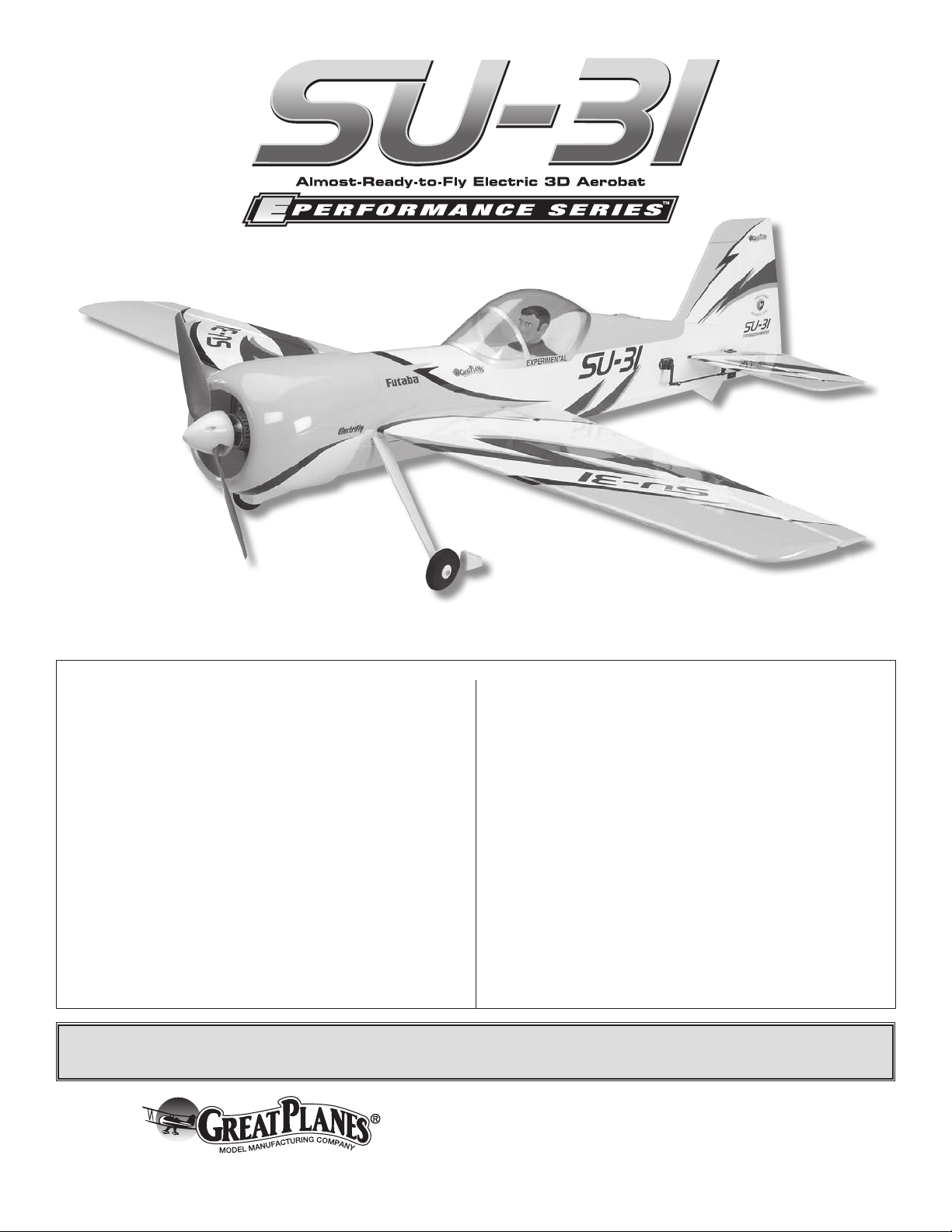
Great Planes GPMA1547 User Manual
Wingspan: 41 in [1040mm]
Wing Area: 343 in2 [22.1dm2]
Weight: 27.5 – 31 oz [780 – 880g]
Wing Loading: 11.5 – 13 oz/ft2 [35 – 40g/dm2]
Length: 38 in [965mm]
Radio: 4+ channel transmitter, 4 micro servos
INSTRUCTION MANUAL
Motor: RimFire™ .10 (35 -30 -1250) out-runner brushless motor
ESC: SS-35 35A brushless ESC
Battery: 3-cell 1250 to 2100mAh LiPo battery and
LiPo compatible charger
WARRANTY
Great Planes® Model Manufacturing Co. guarantees this kit to be
free from defects in both material and workmanship at the date
of purchase. This warranty does not cover any component parts
damaged by use or modification. In no case shall Great Planes’
liability exceed the original cost of the purchased kit. Further,
Great Planes reserves the right to change or modify this warranty
without notice.
In that Great Planes has no control over the final assembly or
material used for final assembly, no liability shall be assumed nor
accepted for any damage resulting from the use by the user of
the final user-assembled product. By the act of using the userassembled product, the user accepts all resulting liability.
If the buyer is not prepared to accept the liability associated
with the use of this product, the buyer is advised to return
this kit immediately in new and unused condition to the place
of purchase.
To make a warranty claim send the defective part or item to Hobby
Services at the address below:
Hobby Services
3002 N. Apollo Dr., Suite 1
Champaign, IL 61822 USA
Include a letter stating your name, return shipping address, as
much contact information as possible (daytime telephone number,
fax number, e-mail address), a detailed description of the problem
and a photocopy of the purchase receipt. Upon receipt of the
package the problem will be evaluated as quickly as possible.
READ THROUGH THIS MANUAL BEFORE STARTING CONSTRUCTION. IT CONTAINS IMPORTANT
INSTRUCTIONS AND WARNINGS CONCERNING THE ASSEMBLY AND USE OF THIS MODEL.
Champaign, Illinois
(217) 398-8970, Ext 5
airsupport@greatplanes.com
Entire Contents © Copyright 2009 GPMA1547MNL V2.0
TABLE OF CONTENTS
INTRODUCTION ............................................................... 2
AMA ..................................................................................2
SAFETY PRECAUTIONS ................................................. 2
DECISIONS YOU MUST MAKE ........................................3
Radio Equipment .......................................................... 3
Motor Recommendation ............................................... 3
Propeller ....................................................................... 3
Electronic Speed Control (ESC) ................................... 3
Battery Pack ................................................................. 3
Required Adhesive & Building Supplies ....................... 4
OPTIONAL SUPPLIES & TOOLS ..................................... 4
IMPORTANT BUILDING NOTES ...................................... 4
ORDERING REPLACEMENT PARTS .............................. 4
KIT INSPECTION .............................................................. 5
KIT CONTENTS ................................................................ 5
PREPARATIONS ............................................................... 6
ASSEMBLE THE WING PANELS ..................................... 6
INSTALL THE WING PANELS .......................................... 8
ASSEMBLE THE TAIL SECTION ..................................... 9
INSTALL THE TAIL SERVOS & PUSHRODS ................. 11
INSTALL THE LANDING GEAR ..................................... 12
MOUNT THE MOTOR, ESC & RECEIVER ..................... 13
INSTALL THE COWL, CANOPY & SPINNER ................ 16
Apply the Decals ........................................................ 17
GET THE MODEL READY TO FLY ................................. 18
Check the Control Directions .....................................18
Set the Control Throws ...............................................18
Balance the Model (C.G.) ........................................... 19
Balance the Model Laterally ....................................... 19
PREFLIGHT .................................................................... 19
Identify Your Model ..................................................... 19
Charge the Batteries .................................................. 20
Balance Propellers ..................................................... 20
Range Check .............................................................20
MOTOR SAFETY PRECAUTIONS ................................. 20
LITHIUM BATTERY HANDLING & USAGE ................... 20
AMA SAFETY CODE (excerpts) .................................... 21
CHECK LIST ................................................................... 21
FLYING ............................................................................ 22
Takeoff ........................................................................ 22
Flight ..........................................................................22
Landing ......................................................................22
3D FLYING ......................................................................23
For the latest technical updates or manual corrections to
the Sukhoi SU-31 EP ARF visit the Great Planes web site
at www.greatplanes.com. Open the “Airplanes” link, then
select the Sukhoi SU-31 EP ARF. If there is new technical
information or changes to this model a “tech notice” box will
appear in the upper left corner of the page.
AMA
If you are not already a member
of the AMA, please join! The
AMA is the governing body of
model aviation and membership
provides liability insurance
coverage, protects modelers’
rights and interests and is
required to fly at most R/C sites.
The AMA has two classes of membership available. Open
membership or their Park Pilot Program which this aircraft
qualifies for. The Park Pilot Program is for people flying
electric aircraft and gliders under two pounds and which
fly slower than 60mph. This will enable you to enjoy most
AMA benefits and organize clubs and flying sites in more
congested areas.
Academy of Model Aeronautics
5151 East Memorial Drive
Muncie, IN 47302-9252
Tele. (800) 435-9262
Fax (765) 741-0057
Or via the Internet at:
http://www.modelaircraft.org
http://www.modelaircraft.org/parkflyer.aspx
IMPORTANT!!! Two of the most important things you can do
to preserve the radio controlled aircraft hobby are to avoid
flying near full-scale aircraft and avoid flying near or over
groups of people.
INTRODUCTION
Congratulations on your purchase of the Great Planes Sukhoi
SU-31 EP ARF! Like the other models in the E-Performance
line, the Sukhoi SU-31 EP ARF will deliver the performance
that 3D pilots are looking for as well as being a great sport
plane for the casual flier. As a new feature, the Sukhoi SU-31
EP ARF is designed with removable wing panels around a
carbon wing tube for transporting convenience. However,
the compact wingspan of the Sukhoi will allow it to fit into
most vehicles in one piece.
PROTECT YOUR MODEL, YOURSELF
& OTHERS....FOLLOW THESE
IMPORTANT SAFETY PRECAUTIONS
1. Your Sukhoi SU-31 EP ARF should not be considered a toy,
but rather a sophisticated, working model that functions very
much like a full-size airplane. Because of its performance
capabilities, the Sukhoi SU-31 EP ARF, if not assembled and
operated correctly, could possibly cause injury to yourself or
spectators and damage to property.
2. You must assemble the model according to the instructions.
Do not alter or modify the model, as doing so may result in an
unsafe or unflyable model. In a few cases the instructions may
differ slightly from the photos. In those instances the written
instructions should be considered as correct.
2

3. You must take time to build straight, true and strong.
4. You must use an R/C radio system that is in first-class
condition, and a correctly sized motor and components
throughout the building process.
5. You must correctly install all R/C and other components
so that the model operates correctly on the ground and in
the air.
receiver battery. Two 6" [150mm] servo extensions and two
12" [305mm] servo extensions are also required. Order
numbers for these items are provided below.
o (4) Futaba
7.7g (FUTM0414)
–OR
®
S3114 Micro High Torque Servo
–
o (4) Futaba S3154 Digital Micro High Torque
High Speed Servo (FUTM0654)
6. You must check the operation of the model before every
flight to insure that all equipment is operating and that the
model has remained structurally sound. Be sure to check
clevises or other connectors often and replace them if they
show any signs of wear or fatigue.
7. If you are not an experienced pilot or have not flown
this type of model before, we recommend that you get the
assistance of an experienced pilot in your R/C club for
your first flights. If you’re not a member of a club, your local
hobby shop has information about clubs in your area whose
membership includes experienced pilots.
8. While this kit has been flight tested to exceed normal use,
if the plane will be used for extremely high stress flying, such
as racing, or if a motor larger than one in the recommended
range is used, the modeler is responsible for taking steps to
reinforce the high stress points and/or substituting hardware
more suitable for the increased stress.
We, as the kit manufacturer, provide you with a top quality,
thoroughly tested kit and instructions, but ultimately the
quality and flyability of your finished model depends
on how you build it; therefore, we cannot in any way
guarantee the performance of your completed model,
and no representations are expressed or implied as to the
performance or safety of your completed model.
–PLUS
–
o Futaba R617FS 2.4 GHz Receiver (FUTL7627)
o (2) Futaba C-25 Extension Slim Wire 150mm (FUTM4506)
o (2) Futaba C-26 12" [300mm] Slim Servo Extension
Futaba J (FUTM4507)
o Futaba 6" Dual Servo Extension J (FUTM4130)
Motor Recommendation
The recommended motor for the Sukhoi SU-31 EP ARF is
the Great Planes RimFire™ .10 (35-30-1250) brushless outrunner motor (GPMG4595)
Note: Motors from other manufacturers may work with the
Sukhoi SU-31 EP ARF; however the included motor mounting
components are designed to work specifically with the Great
Planes motor listed.
Propeller
The recommended propeller for the Sukhoi SU-31 EP ARF
when using the Great Planes RimFire .10 (35-30-1250)
motor is the APC 10 x 7" E Propeller (APCQ4123)
Remember: Take your time and follow the instructions to
end up with a well-built model that is straight and true.
DECISIONS YOU MUST MAKE
This is a partial list of items required to finish the Sukhoi
SU-31 EP ARF that may require planning or decision
making before starting to build. Order numbers are provided
in parentheses.
Radio Equipment
A 4-channel radio system with four micro servos and a small
receiver are required for this plane. The servos and receiver
shown in the manual are Futaba S3114 micro servos and
the Futaba® R617FS receiver. If you are planning on doing
extreme, high stress 3D flying, it is recommended that you
use the Futaba S3154 micro servos instead of the Futaba
S3114 servos. If using any of the S3154 servos it is also
recommended that you use an external BEC or separate
Electronic Speed Control (ESC)
A brushless ESC is required for this plane. We recommend
using the Great Planes Silver Series 35A Brushless ESC
5V/2A BEC (GPMM1830).
Battery Pack
The Sukhoi SU-31 EP ARF has been tested with 11.1V LiPo
packs ranging from 1250mAh to 2100mAh. Order numbers
are provided for packs of this size. The more powerful
2100mAh pack is suggested for maximum performance.
o Great Planes LiPo 1250mAh 11.1V 20C Discharge
w/Balance (GPMP0609)
o Great Planes LiPo 1500mAh 11.1V 20C Discharge
w/Balance (GPMP0613)
o Great Planes LiPo 2100mAh 11.1V 20C Discharge
w/Balance (GPMP0617)
3

Required Adhesive & Building Supplies
This is the list of adhesive and building supplies required
to finish the Sukhoi SU-31 EP ARF. Order numbers are
provided in parentheses.
o 1/2 oz. [15g] Thin Pro
™
CA (GPMR6001)
o 1/2 oz. [15g] Medium Pro CA+ (GPMR6007)
o Pro 30-minute epoxy (GPMR6047)
o Denatured alcohol
o Drill bits: 1/8" [3mm]
o #1 Hobby knife (HCAR0105)
o #11 Blades (5-pack, HCAR0211)
o Hobbico
®
steel T-Pins 1" [25mm] (100) (HCAR5100)
o Great Planes Pro Threadlocker (GPMR6060)
o CA applicator tips (HCAR3780)
o 220-grit Sandpaper
o Masking tape
OPTIONAL SUPPLIES & TOOLS
• Photos and sketches are placed before the step they
refer to. Frequently you can study photos in following
steps to get another view of the same parts.
• The stabilizer and wing incidences and motor thrust
angles have been factory-built into this model. However,
some technically-minded modelers may wish to check
these measurements anyway. To view this information
visit the web site at www.greatplanes.com and click on
“Technical Data.” Due to manufacturing tolerances which
will have little or no effect on the way your model will fly,
please expect slight deviations between your model and
the published values.
ORDERING REPLACEMENT PARTS
Replacement parts for the Great Planes Sukhoi SU-31
EP ARF are available using the order numbers in the
Replacement Parts List that follows. The fastest, most
economical service can be provided by your hobby dealer or
mail-order company.
Here is a list of optional tools mentioned in the manual that
will help you build the Sukhoi SU-31 EP ARF.
o 21st Century
®
sealing iron (COVR2700)
o 21st Century iron cover (COVR2702)
o 2 oz. [57g] Spray CA activator (GPMR6035)
o 4 oz. [113g] Aerosol CA activator (GPMR6034)
o CA debonder (GPMR6039)
o Epoxy brushes (6, GPMR8060)
o Mixing sticks (50, GPMR8055)
o Mixing cups (GPMR8056)
o Panel line pen (TOPQ2510)
o Rotary tool such as Dremel
®
o Hobbico flexible 18" [457mm] stainless steel
ruler (HCAR0460)
o Hobbico heavy duty diagonal cutter
7" [178mm](HCAR0627)
IMPORTANT BUILDING NOTES
• When you see the term test fit in the instructions,
it means that you should first position the part on the
assembly without using any glue, then slightly modify
or custom fit the part as necessary for the best fit.
• Wheneverthetermglue is written you should rely upon
your experience to decide what type of glue to use. When
a specific type of adhesive works best for that step, the
instructions will make a recommendation.
• Wheneverjust epoxy is specified you may use either
30-minute (or 45-minute) epoxy or 6-minute epoxy. When
30-minute epoxy is specified it is highly recommended
that you use only 30-minute (or 45-minute) epoxy,
because you will need the working time and/or the
additional strength.
To locate a hobby dealer, visit the Hobbico web site at
www.hobbico.com. Choose “Where to Buy” at the
bottom of the menu on the left side of the page. Follow the
instructions provided on the page to locate a U.S., Canadian
or International dealer.
Parts may also be ordered directly from Hobby Services by
calling (217) 398-0007, or via facsimile at (217) 398-7721,
but full retail prices and shipping and handling charges will
apply. Illinois and Nevada residents will also be charged
sales tax. If ordering via fax, include a Visa® or MasterCard®
number and expiration date for payment.
Mail parts orders Hobby Services
and payments by 3002 N. Apollo Drive, Suite 1
personal check to: Champaign, IL 61822
Be certain to specify the order number exactly as listed in
the Replacement Parts List. Payment by credit card or
personal check only; no C.O.D.
If additional assistance is required for any reason contact Product
Support by e-mail at productsupport@greatplanes.com, or
by telephone at (217) 398-8970.
Replacement Parts List
Description How to Purchase
Missing pieces Contact Product Support
Instruction manual Contact Product Support
Full-size plans Not available
Contact your hobby supplier for the following parts:
GPMA3125 Wing Kit GPMA3130 Cowl
GPMA3126 Fuselage Kit GPMA3131 Canopy
GPMA3127 Tail Set GPMA3132 Wing Tube
GPMA3128 Landing Gear GPMA3133 Decal
GPMA3129 Wheel Pants GPMA3134 Battery Hatch
4
KIT INSPECTION
Before starting to build, take an inventory of this kit to make sure it is complete and inspect the parts to make sure they
are of acceptable quality. If any parts are missing or are not of acceptable quality, or if you need assistance with assembly,
contact Product Support. When reporting defective or missing parts, use the part names exactly as they are written in
the Kit Contents list.
Great Planes Product Support:
3002 N. Apollo Drive, Suite 1
Champaign, IL 61822
Telephone: (217) 398-8970, ext. 5
Fax: (217) 398-7721
E-mail: airsupport@greatplanes.com
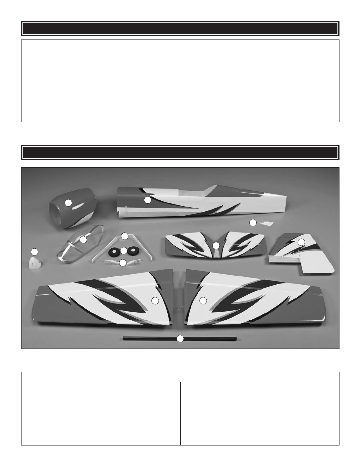
KIT CONTENTS
1
4
3
5
6
7
2
9
10
13
13
8
1212121211
1 Cowl
2 Fuselage
3 Spinner
4 Canopy
5 Main Landing Gear (L&R)
6 Main Wheels (2)
7 Wheel Spats (L&R)
8 Horizontal Stabilizer & Elevators
Kit Contents
9 Tail Skid
10 Vertical Fin & Rudder
11 Right Wing Panel w/Aileron
12 Left Wing Panel w/Aileron
13 Wing Tube
5
PREPARATIONS
o 1. If you have not done so already, remove the major parts
of the kit from the box and inspect for damage. If any parts
are damaged or missing, contact Product Support at the
address or telephone number listed in the “Kit Inspection”
section on page 5.
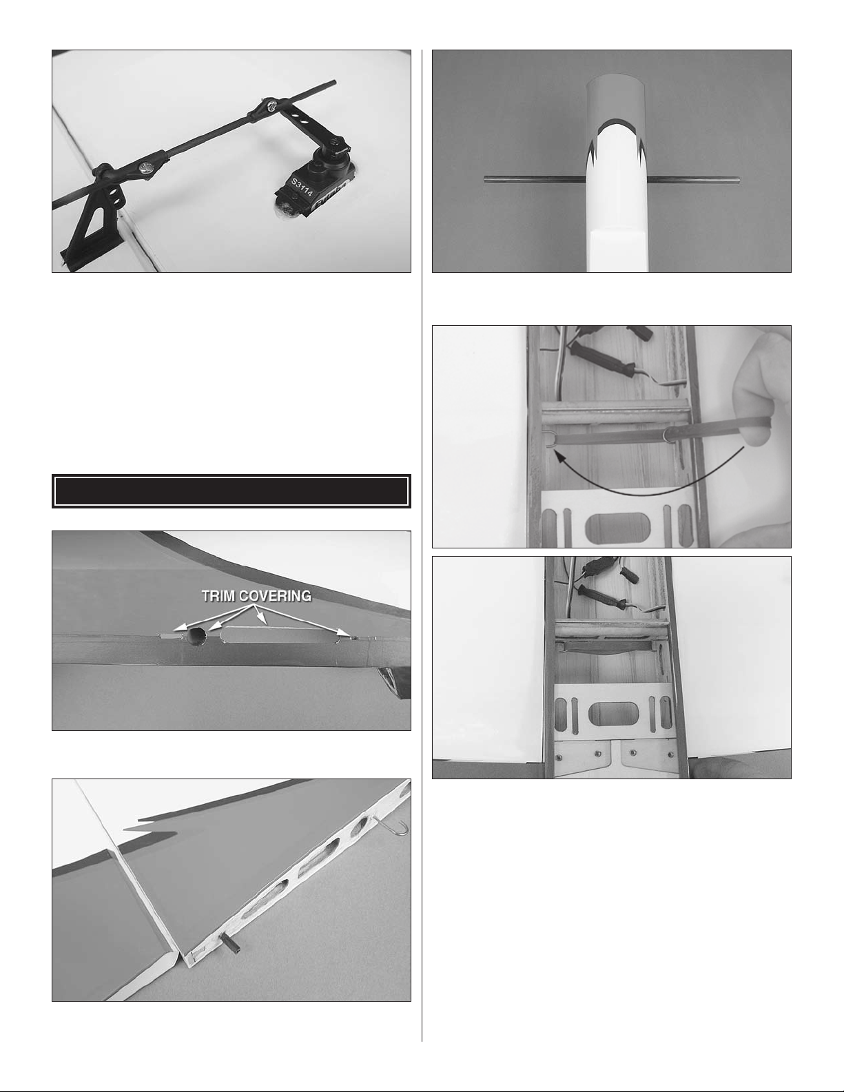
o 2. Carefully remove the tape on the horizontal stabilizer
and separate the elevators. Use a covering iron with a
covering sock on medium/high heat to tighten the covering if
necessary. Apply pressure over sheeted areas to thoroughly
bond the covering to the wood.
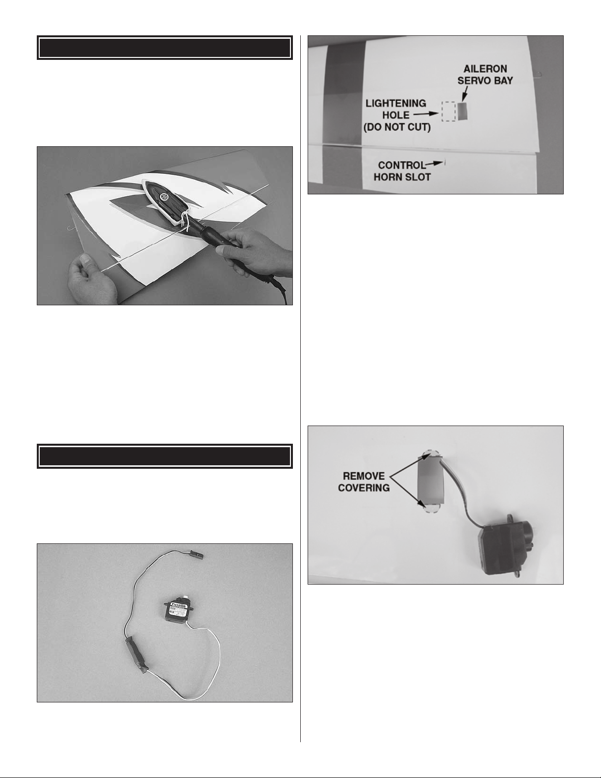
o 3. Trim the covering from the aileron servo bays on the
undersides of the wing panels. Also trim the covering from
the control horn slots in the ailerons. Note: The servo bay
is on the inside portion of the servo mounting plate. There
is a lightening hole on the outboard portion of the servo
mounting plate that may easily be mistaken for the servo
mounting position.
ASSEMBLE THE WING PANELS
o 1. The aileron hinges for the SU-31 have been preinstalled.
Please check them to be certain they are properly glued. If
any of them are loose simply add a few drops of thin CA glue
to the top and bottom of the hinge.
o 2. Attach a 6" [152mm] servo extension to each aileron
servo and wrap the connection with electrical tape or 3/8"
[9.5mm] diameter heat shrink tubing (not included).
o 4. Insert the servo leads into the servo bays and pull them
through the wing ribs. The servos can be installed using the
hardware included with the servos or they can be glued in
place. If gluing the servos in place, remove the covering just
beneath the servo mounting tabs where they will contact
the wing. This will ensure that the servo will be glued to the
plywood servo bay, not just the covering. Roughing up the
underside of each servo mounting tab with sandpaper will
also improve glue adhesion. Glue the aileron servos into the
servo bays using epoxy or CA glue with the servo splines
facing the leading edge of the wings. After the glue has
cured, confirm that the servos are properly secured to the
wings and reinforce with extra glue if necessary.
66
6
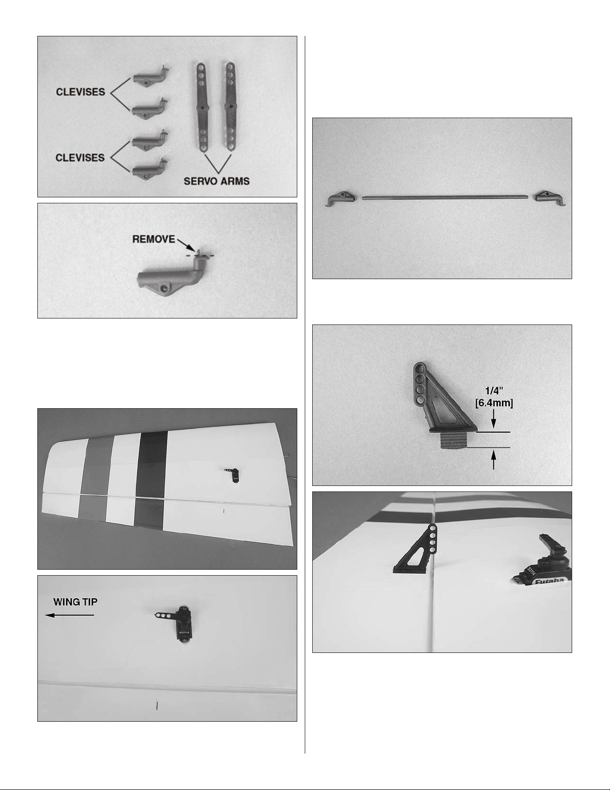
o 5. Locate two double-sided servo arms that fit the output
splines of your aileron servos. Also, locate four adjustable
clevises. If necessary, remove the flashing from the top of
the clevises using some sandpaper. Be certain that the
flashing is fully removed, or it will be very difficult to install
the clevises.
transmitter. Test fit the double-sided servo arms parallel to
the aileron hinge line. Decide which way fits best (closest to
parallel) and cut off the arm that isn’t used. The remaining
arm should point toward the wing tip. Be sure to make a left
and right servo arm.
o 7. Fit an adjustable clevis onto both 2 x 100mm aileron
pushrods.
o 6. Temporarily connect the aileron servos and battery
pack to your radio. Center the servos and trim levers on the
o 8. Trim the mounting tabs on two control horns so that
they are 1/4" [6.4mm] long. Test fit the control horn into the
control horn slot in the wing. Check to be sure that the horn
holes sit over the hinge line. If they do not, use a hobby knife
to enlarge the slot so that the horn holes sit over the hinge
line. Coat the control horn mounting tabs with medium CA
and press them into the slots in the ailerons.
7
o 9. Fit the clevises on the aileron pushrods into the outer
holes of the aileron control horns and servo arms as shown.
(You may need to temporarily remove the servo arms from
the servos.) With the servo arms parallel to the hinge lines
and the ailerons in the neutral positions, center the length
of the pushrods between the two clevises. When satisfied,
lock the clevises onto the pushrods by threading a 2 x 4mm
screw into each clevis screw hole. The screw head should fit
into the recessed hole in the adjustable clevises as shown
(installing the screws in the wrong direction may not properly
tighten the clevises onto the pushrods).
INSTALL THE WING PANELS
o 3. Slide the carbon wing tube into the wing tube channel
in the fuselage and center its position.
o 1. Trim the covering in the fuselage for the wing tube, wing
mounting hooks, servo lead holes and anti-rotation pin.
o 2. Glue the 3 x 15mm carbon anti-rotation pins halfway
into the holes in the wing root ribs using medium CA glue.
o 4. Slide the wing panels onto the wing tube and push them
in place against the fuselage sides by fitting the anti-rotation
pins into their mating holes. Secure the wing by hooking one
end of a rubber band to one wing hook, wrapping the rubber
band around the other wing hook and returning the rubber
band to the original wing hook. Further secure the wing with
a second rubber band, installing it in the same manner.
8
8
 Loading...