

Great Planes GPMA1543 User Manual
Wingspan: 41 in [1035mm]
Wing Area: 337 in2 [21.8dm2]
Weight: 27 – 31 oz [765 – 880g]
Wing Loading: 11.5 – 13.2 oz/ft2 [35 – 40g/dm2]
Length: 40 in [1015mm]
Required (not included):
Radio: 4-channel with four micro servos, two 6"
[152mm] servo extensions, two 16" [406mm]
servo extensions one Y-harness
Motor: RimFire™ 35-30-1250kV brushless out-runner
(GPMG4595) or Ammo™ 24-45-3790kV
brushless in-runner (GPMG0505) brushless out-runner
Gear-Drive: 24mm gear-drive with 4.5:1 gear ratio
ESC: 35A Brushless
Battery: 3-cell 1250 to 2100mAh LiPo battery & LiPo
compatible charger
INSTRUCTION MANUAL
Great Planes
®
Model Manufacturing Co. guarantees this kit to be free from def ects in both material and workmanship at the date of purchase.
This warranty does not cover an y component parts damaged by use or modifi cation. In no case shall Great Planes’ liability exceed the
original cost of the purchased kit. Further, Great Planes reserves the right to change or modify this warranty without notice.
In that Great Planes has no control over the fi nal assembly or material used for fi nal assembly, no liability shall be assumed nor accepted
for any damage resulting from the use by the user of the fi nal user-assembled product. By the act of using the user-assembled product,
the user accepts all resulting liability.
If the buyer is not prepared to accept the liability associated with the use of this product, the b uy er is advised to return th is kit
immediately in new and unused condition to the place of purchase.
To make a warranty claim send the defective part or item to Hobby Services at the address below:
Hobby Services
3002 N. Apollo Dr., Suite 1
Champaign, IL 61822 USA
Include a letter stating your name, return shipping address, as much contact information as possible (daytime telephone number, fax
number, e-mail address), a detailed description of the problem and a photocopy of the purchase receipt. Upon receipt of the package
the problem will be evaluated as quickly as possible.
READ THROUGH THIS MANUAL BEFORE
STARTING CONSTRUCTION. IT CONTAINS
IMPORTANT INSTRUCTIONS AND WARNINGS
WARRANTY
CONCERNING THE ASSEMBLY AND USE OF
THIS MODEL.
Champaign, Illinois
(217) 398-8970, Ext 5
airsupport@greatplanes.com
Entire Contents © Copyright 2007 GPMZ1543 for GPMA1543 V1.0
TABLE OF CONTENTS
INTRODUCTION
INTRODUCTION ...............................................................2
AMA ..................................................................................2
SAFETY PRECAUTIONS .................................................2
LITHIUM BATTERY HANDLING & USAGE .....................3
DECISIONS YOU MUST MAKE ........................................3
Radio Equipment ..........................................................3
Motor Recommendations .............................................3
Propeller .......................................................................4
ESC (electronic speed control) ....................................4
Battery Pack .................................................................4
Charger ........................................................................4
Required Adhesive & Building Supplies .......................4
Optional Supplies & Tools ............................................4
IMPORTANT BUILDING NOTES ......................................5
ORDERING REPLACEMENT PARTS ..............................5
COMMON ABBREVIATIONS ...........................................5
METRIC CONVERSIONS .................................................5
KIT INSPECTION ..............................................................6
KIT CONTENTS ................................................................6
PREPARATIONS ...............................................................7
ASSEMBLE THE WING PANELS .....................................7
INST ALL THE WING PANELS ..........................................9
ASSEMBLE THE T AIL SECTION ...................................11
INSTALL THE TAIL SERVOS & PUSHRODS .................13
INSTALL THE LANDING GEAR .....................................13
MOUNT THE MOTOR .....................................................15
In-runner Brushless Motor with 24mm Gear Drive ........15
Out-runner Brushless Motor .......................................16
INSTALL THE RADIO & ESC .........................................17
INSTALL THE COWL, CANOPY & SPINNER ................18
APPL Y THE DECALS .....................................................20
GET THE MODEL READY TO FL Y .................................20
Check the Control Directions .....................................20
Set the Control Throws ...............................................20
Balance the Model (C.G.) ...........................................21
Balance the Model Laterally .......................................21
PREFLIGHT ....................................................................21
Identify Your Model .....................................................21
Charge the Batteries ..................................................21
Balance the Propellers ...............................................22
Range Check .............................................................22
MOTOR SAFETY PRECAUTIONS .................................22
AMA SAFETY CODE (excerpts) ....................................22
CHECK LIST ...................................................................23
FLYING ............................................................................23
Takeoff ........................................................................23
Flight ..........................................................................24
Landing ......................................................................24
3D FLYING ......................................................................24
The Extra 330S EP ARF is another great release in a line of
electric built-up, all out performance 3D planes. You can fl y
incredible 3D maneuvers with the Extra 330S EP ARF just lik e
larger scale, expensiv e gas models . In addition, high capacity
LiPo battery packs and a brushless motor will allow you the
convenience of electric fl ying within a reasonable b udget.
For the latest technical updates or manual corrections to
the Extra 330S EP ARF, visit the Great Planes web site at
www.greatplanes.com. Open the “Airplanes” link, then
select the Extra 330S EP ARF. If there is new technical
information or changes to this model a “tech notice” box will
appear in the upper left corner of the page.
AMA
We urge you to join the AMA (Academy of Model Aeronautics)
and a local R/C club. The AMA is the governing body of model
aviation and membership is required to fl y at AMA clubs.
Though joining the AMA provides many benefi ts, one of the
primary reasons to join is liability protection. Coverage is not
limited to fl ying at contests or on the club fi eld. It e ven applies
to fl ying at public demonstrations and air shows. Failure to
comply with the Safety Code (excerpts printed in the back of
the manual) may endanger insurance cov erage . Additionally,
training programs and instructors are available at AMA club
sites to help you get started the right way. There are over
2,500 AMA chartered clubs across the countr y. Contact the
AMA at the address or toll-free phone number below:
Academy of Model Aeronautics
5151 East Memorial Drive
Muncie, IN 47302-9252
Tele. (800) 435-9262
Fax (765) 741-0057
Or via the Internet at:
http://www.modelaircraft.org
IMPORTANT!!! Two of the most important things you can do
to preserve the radio controlled aircraft hobby are to avoid
fl ying near full-scale aircraft and avoid fl ying near or over
groups of people.
PROTECT Y OUR MODEL, YOURSELF
& OTHERS....FOLLOW THESE
IMPORTANT SAFETY PRECAUTIONS
1. Your Extra 330S EP ARF should not be considered a toy,
but rather a sophisticated, working model that functions very
much like a full-size airplane. Because of its performance
capabilities, the Extra 330S EP ARF, if not assembled and
operated correctly, could possibly cause injury to yourself or
spectators and damage to property.
2

2. Y ou must assemble the model according to the instructions.
Do not alter or modify the model, as doing so may result in an
unsafe or unfl yable model. In a f ew cases the instructions may
differ slightly from the photos. In those instances the written
instructions should be considered as correct.
3. You must take time to build straight, true and strong.
4. You must use an R/C radio system that is in fi rst-class
condition, and a correctly sized engine and components
(fuel tank, wheels, etc.) throughout the building process.
5. You must correctly install all R/C and other components
so that the model operates correctly on the ground and in
the air.
6. You must check the operation of the model before every
fl ight to insure that all equipment is operating and that the
model has remained structurally sound. Be sure to check
clevises or other connectors often and replace them if they
show any signs of wear or fatigue.
7. If you are not an experienced pilot or have not fl own
this type of model before, we recommend that you get the
assistance of an experienced pilot in your R/C club for
your fi rst fl ights. If you’re not a member of a club, your local
hobby shop has information about clubs in your area whose
membership includes experienced pilots.
8. While this kit has been fl ight tested to exceed normal use,
if the plane will be used for extremely high-stress fl ying, such
as racing, or if a motor larger than one in the recommended
range is used, the modeler is responsible for taking steps to
reinforce the high-stress points and/or substituting hardware
more suitable for the increased stress.
We, as the kit manuf acturer, provide you with a top quality,
thoroughly tested kit and instructions, but ultimately the
quality and fl yability of your fi nished model depends
on how you build it; therefore, we cannot in any way
guarantee the performance of your completed model,
and no representations are expressed or implied as to the
performance or safety of your completed model.
• NEVER charge at currents greater than 1C.
• ALWAYS set the charger’s output volts to match the
battery volts.
• ALWAYS charge in a fi reproof location.
• NEVER trickle charge.
• NEVER allow the battery temperature to exceed
150° F [65° C].
• NEVER disassemble or modify pack wiring in any way or
puncture cells.
• NEVER discharge below 2.5V per cell.
• NEVER place on combustible materials or leave
unattended during charge or discharge.
• ALWAYS KEEP OUT OF REACH OF CHILDREN.
DECISIONS YOU MUST MAKE
This is a partial list of items required to fi nish the Extra 330S
EP ARF that may require planning or decision making before
starting to build. Order numbers are provided in parentheses.
Radio Equipment
A 4-channel radio system with four micro servos and a micro
receiver are required for this model. The servos and receiver
shown in the manual are Futaba® S3114 micro servos and
the Futaba R114F micro receiver. Two 6" [150mm] servo
extensions, two 16" [400mm] servo extensions, and a
Y-harness are also required. Order numbers for these items
are provided.
❏ (4) Futaba S3114 Micro High Torque Servo
7.7g (FUTM0414)
❏ Futaba R114F FM Micro Receiver (Low Band – FUTL0442,
High Band – FUTL0443)
❏ Futaba FM Single Conversion Short Crystal
(Low Band – FUTL62**, High Band – FUTL63**)
❏ (2) Futaba C-25 Extension Slim Wire 150mm (FUTM4506)
❏ (2) Futaba “J” 16" [400mm] Servo Extension (FUTM3955)
❏ Futaba “J” 6" Dual Servo Extension (FUTM4130)
Remember: T ake your time and f ollow the instructions to
end up with a well-built model that is straight and true.
LITHIUM BATTERY HANDLING & USAGE
WARNING!! Read the entire instruction sheet included with
this battery. Failure to follow all instructions could cause
permanent damage to the battery and its surroundings and
cause bodily harm!
• ONLY use a LiPo approved charger. NEVER use a NiCd/
NiMH peak charger!
• NEVER charge in excess of 4.20V per cell.
• ONLY charge through the “charge” lead. NEVER charge
through the “discharge” lead.
Motor Recommendations
The Extra 330S EP ARF comes with two mounting box es that will
accommodate either a brushless in-runner motor with gear drive
or a brushless out-runner motor. For all-out 3D performance,
we suggest the out-runner motor. For sport fl ying, either motor
choice is acceptable. The motors that have been tested and
perform well in this plane are listed below. If using the in-runner
motor with gear drive, be sure to install the 11T pinion that is
included with the gear drive to achieve a gear r atio of 4.5:1.
❏ Great Planes RimFire
out-runner motor (GPMG4595)
❏ Great Planes Ammo™ 24-45-3790kV brushless in-runner
motor (GPMG5185)
™
35-30-1250kV brushless
❏ Great Planes Gear Drive 24mm motors (GPMG0505)
3

Note: Motors from other manufacturers may work with the
Extra 330S EP ARF. However, the included fi rewall pieces
are designed to work specifi cally with the Great Planes
motors listed.
Propeller
If using the Ammo brushless in-runner motor with 4.5:1 gearbox
or the RimFire brushless out-runner motor, we recommend a
10" x 7" E Slo-Flyer electric propeller (GPMQ4123).
™
Triton2
is capable of charging NiCd, NiMH, LiPo, and lead acid
batteries. Order numbers for both are provided as follows:
charger will only charge one pack at a time, but
❏ Great Planes PolyCharge4 DC Only 4 Output LiPo
Charger (GPMM3015)
or
❏ Great Planes ElectriFly Triton2 DC Comp Peak
Charger (GPMM3153)
Required Adhesive & Building Supplies
ESC (electronic speed control)
A brushless ESC (electronic speed control) is required for
this plane. We recommend using the Great Planes Silver
Series 35A Brushless ESC 5V/2A BEC (GPMM1830).
Battery Pack
The Extra 330S EP ARF has been tested with 11.1V LiPo
packs ranging from 1250mAh to 2100mAh. Order numbers
are provided for packs of this siz e. The lighter 1250mAh pac k
is suggested for maximum performance.
❏ Great Planes LiPo 1250mAh 11.1V 20C Discharge
w/Balance (GPMP0609)
❏ Great Planes LiPo 1500mAh 11.1V 20C Discharge
w/Balance (GPMP0613)
❏ Great Planes LiPo 2100mAh 11.1V 15C w/Balance
BP2100 (GPMP0721)
Note: Do not use Great Planes LiPo 1500mAh 11.1V
3S 8C Discharge (GPMP0831). This battery pack is not
capable of supporting the current draw of the recommended
power systems.
Also, if using a 1250mAh battery pack combined with the
brushless out-runner motor, avoid prolonged full throttle
fl ying since the current draw of the motor exceeds the
continuous maximum current draw rating of the battery pack.
The 1250mAh battery pack is capable of supporting shorter,
full throttle maneuvers.
Charger
This is the list of adhesive and building supplies required to
fi nish the Extra 330S EP ARF. Order numbers are provided
in parentheses.
❏ 1/2 oz. [15g] Thin Pro
™
CA (GPMR6001)
❏ 1/2 oz. [15g] Medium Pro CA+ (GPMR6007)
❏ Pro 30-minute epoxy (GPMR6047)
❏ Denatured alcohol
❏ Drill bits: 1/8" [3mm]
❏ #1 Hobby knife (HCAR0105)
❏ #11 blades (5-pack, HCAR0211)
❏ Hobbico Steel T-pins 1" (100) (HCAR5100)
❏ Great Planes Pro Threadlocker (GPMR6060)
❏ CA applicator tips (HCAR3780)
❏ Small spring clamps
❏ 220-grit Sandpaper
Optional Supplies & Tools
Here is a list of optional tools mentioned in the manual that
will help you build the Extra 330S EP ARF.
❏ 21st Century
®
sealing iron (COVR2700)
❏ 21st Century iron cover (COVR2702)
❏ 2 oz. [57g] Spray CA activator (GPMR6035)
❏ 4 oz. [113g] Aerosol CA activator (GPMR6034)
❏ CA debonder (GPMR6039)
❏ Epoxy brushes (6, GPMR8060)
❏ Mixing sticks (50, GPMR8055)
❏ Mixing cups (GPMR8056)
❏ Hobbico Duster
™
can of compressed air (HCAR5500)
❏ Panel Line pen (TOPQ2510)
❏ Rotary tool such as Dremel
®
❏ Hobbico fl exible 18" ruler stainless steel (HCAR0460)
Note: A cell balancer is required for the LiPo battery packs
listed above.
❏ Great Planes ElectriFly
(GPMM3160)
A suitable charger is also required. The Great Planes
PolyCharge4™ is designed for LiPo packs only, but is able
to charge four LiPo packs simultaneously. The Great Planes
™
Equinox LiP o 1 to 5 Cell Balancer
4

IMPORTANT BUILDING NOTES
Be certain to specify the order number exactly as listed in
the Replacement Parts List. Payment is by credit card or
personal check only; no C.O.D.
• When you see the term test fi t in the instructions, it
means that you should fi rst position the part on the assembly
without using any glue, and then slightly modify or custom
fi t the part as necessary for the best fi t.
• Whenever the term glue is written you should rely upon
your experience to decide what type of glue to use. When
a specifi c type of adhesive works best for that step, the
instructions will make a recommendation.
• Whenever just epoxy is specifi ed you may use either
30-minute (or 45-minute) epoxy or 6-minute epoxy. When
30-minute epoxy is specifi ed it is highly recommended that
you use only 30-minute (or 45-minute) epoxy, because you
will need the working time and/or the additional strength.
• Photos and sketches are placed before the step they
refer to. Frequently you can study photos in following steps
to get another view of the same parts.
• The stabilizer and wing incidences and engine thrust
angles have been factory-built into this model. However,
some technically-minded modelers may wish to check these
measurements anyway. To view this inf ormation visit the web
site at www.greatplanes.com and click on “Technical Data.”
Due to manufacturing tolerances which will have little or no
effect on the way your model will fl y, please expect slight
deviations between your model and the published values.
ORDERING REPLACEMENT PARTS
If additional assistance is required for any reason contact Product
Support by e-mail at productsupport@greatplanes.com,
or by telephone at (217) 398-8970.
Replacement Parts List
GPMA3040 Wing Set
GPMA3041 Fuse
GPMA3042 Tail Surfaces
GPMA3043 Landing Gear
GPMA3044 Wheel Pants
GPMA3045 Cowl
GPMA3046 Canopy
GPMA3047 Battery Hatch
GPMA3048 Decals
GPMA2981 Spinner
GPMA2982 Hardware Set
COMMON ABBREVIATIONS
Fuse = Fuselage
Stab = Horizontal Stabilizer
Fin = Vertical Fin
LE = Leading Edge
TE = Trailing Edge
LG = Landing Gear
Ply = Plywood
" = Inches
mm = Millimeters
ESC = Electronic Speed Control
METRIC CONVERSIONS
Replacement parts for the Great Planes Extra 330S EP ARF
are available using the order numbers in the Replacement
Parts List that follows. The fastest, most economical service
can be provided by your hobby dealer or mail-order company.
To locate a hobby dealer, visit the Hobbico web site at
www.hobbico.com. Choose “Where to Buy” at the
bottom of the menu on the left side of the page. Follow the
instructions provided on the page to locate a U.S., Canadian
or International dealer.
Parts may also be ordered directly from Hobby Services by
calling (217) 398-0007, or via facsimile at (217) 398-7721,
but full retail prices and shipping and handling charges will
apply. Illinois and Nevada residents will also be charged
sales tax. If ordering via fax, include a Visa® or MasterCard®
number and expiration date for payment.
Mail parts orders and payments by personal check to:
Hobby Services
3002 N. Apollo Drive, Suite 1
Champaign, IL 61822
1" = 25.4mm (conversion factor)
1/64" = .4mm
1/32" = .8mm
1/16" = 1.6mm
3/32" = 2.4mm
1/8" = 3.2mm
5/32" = 4.0mm
3/16" = 4.8mm
1/4" = 6.4mm
3/8" = 9.5mm
1/2" = 12.7mm
5/8" = 15.9mm
5
3/4" = 19.0mm
1" = 25.4mm
2" = 50.8mm
3" = 76.2mm
6" = 152.4mm
12" = 304.8mm
18" = 457.2mm
21" = 533.4mm
24" = 609.6mm
30" = 762.0mm
36" = 914.4mm
KIT INSPECTION
KIT INSPECTION
KIT CONTENTS
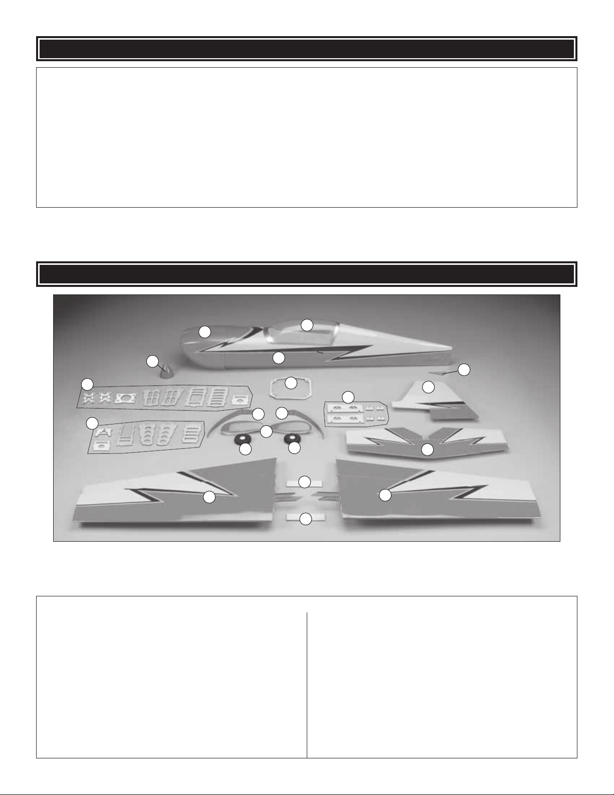
Before starting to build, take an inventory of this kit to make sure it is complete and inspect the parts to make sure they
are of acceptable quality. If any parts are missing or are not of acceptable quality, or if you need assistance with assembly,
contact Product Support. When reporting defective or missing parts, use the part names exactly as they are written in
the Kit Contents list.
Great Planes Product Support:
3002 N Apollo Drive, Suite 1
Champaign, IL 61822
Telephone: (217) 398-8970, ext. 5
Fax: (217) 398-7721
E-mail: airsupport@greatplanes.com
KIT CONTENTS
1
5
6
8
7
9
10
15
3
2
4
11
12
8
10
16
17
16
13
14
Kit Contents
1 Cowl
2 Fuse
3 Canopy
4 Tail Skid
5 Spinner
6 Out-Runner Motor Mounting Box (8 pcs.)
7 In-Runner Motor Mounting Box (6 pcs.)
8 Landing Gear (2 pcs.)
9 Wheel Pants (L&R)
10 Wheels (2 pcs.)
11 Cowl Ring
12 Wing Alignment Jig (6 pcs.)
13 Vertical Fin & Rudder
14 Horizontal Stabilizer & Elevators
15 Right Wing Panel & Aileron
16 Spar Doublers (2 pcs.)
17 Left Wing Panel & Aileron
6
PREPARATIONS
❏ 1. If you have not done so already, remove the major parts
of the kit from the box and inspect for damage. If any par ts
are damaged or missing, contact Product Support at the
address or telephone number listed in the “Kit Inspection”
section on page 6.
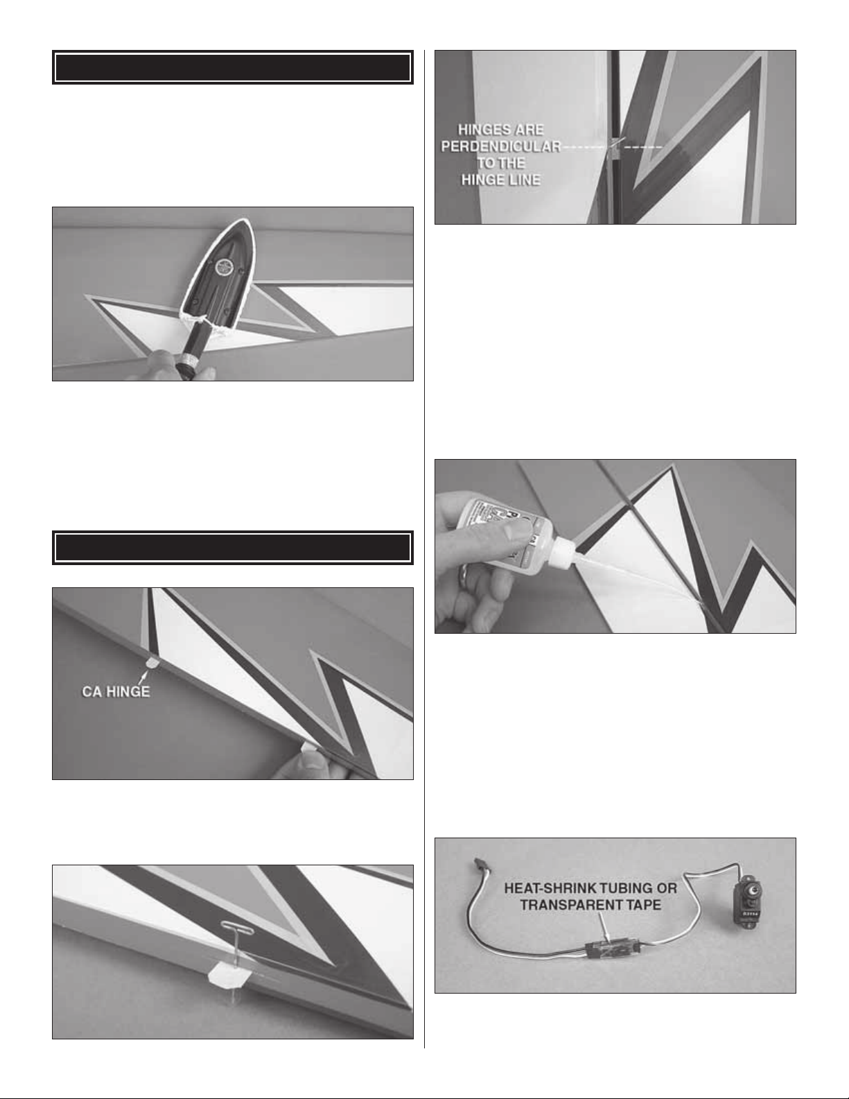
❏ 2. Carefully remove the tape and separate all the control
surfaces. Use a co v ering iron with a covering sock on medium
heat to tighten the covering if necessary. Apply pressure over
sheeted areas to thoroughly bond the cov ering to the wood.
❏ 2. Insert the CA hinges halfway into the slots in the wing
panels. Push small T-pins through the middle of the hinges to
keep them centered. Insert the ailerons onto the other ends
of the hinges. Align the outer tips of the ailerons fl ush with the
wing tips. Pull the ailerons away from the panels far enough
to confi r m that the hinges remained perpendicular with the
hinge line. If not, use a hobby knife or small screwdr iver to
nudge them straight.
ASSEMBLE THE WING P ANELS
❏ 1. Use a sharp hobby knife to trim open the hinge slots in
the wing panels and ailerons. Test fi t the pre-cut CA hinges
into the slots. If any are diffi cult to install, enlarge the slots
with your knife.
❏ 3. When satisfi ed, carefully remove the T-pins from the
hinges. Adjust the ailerons so there is a small gap between
the LE of the aileron and the wing. The gap should be small,
just enough to see light through the gap or slip a piece of
paper through. Use thin CA glue to secure the ailerons by
applying 6 to 7 drops onto both sides of each hinge.
❏ 4. Attach a 6" [152mm] servo extension to each aileron
servo and wrap the connection with transparent tape or heatshrink tubing.
7

❏ 5. Trim the covering from the aileron servo bays on the
undersides of the wing panels.
❏ 6. Insert the servo leads into the servo bays and pull them
through the wing ribs. The servos can be installed using
the hardware included with the servos or they can be glued
in place. If gluing the servos in place, slit or puncture the
covering just beneath the servo mounting tabs where they
will contact the wing. This will ensure that the servo will be
glued to the plywood servo bay, not just the covering. Glue
the aileron servos into the servo bays using epoxy or CA glue
with the servo splines facing the LE of the wings. After the
glue has cured, confi rm that the servos are properly secured
to the wings and reinforce with extra glue if necessary.
❏ 8. Temporarily connect your aileron servos and battery
pack to your radio and center the servos and trim levers on
the transmitter. Test fi t the double-sided servo arms parallel
to the aileron hinge line. If the servo arm does not fi t onto
the servo spline parallel to the hinge line, remove it from the
servo and rotate it 180°. Decide which way fi ts best (closest
to parallel) and cut off the arm that isn’t used. Be sure to
make a left and right servo arm.
❏ 7. Locate two double-sided servo arms that fi t the output
splines of your aileron servos and four adjustable clevises.
❏ 9. Fit two adjustable clevises onto both 2mm x 90mm
aileron pushrods. Push one of the clevises from each
pushrod into the outer holes of the servo arms.
8
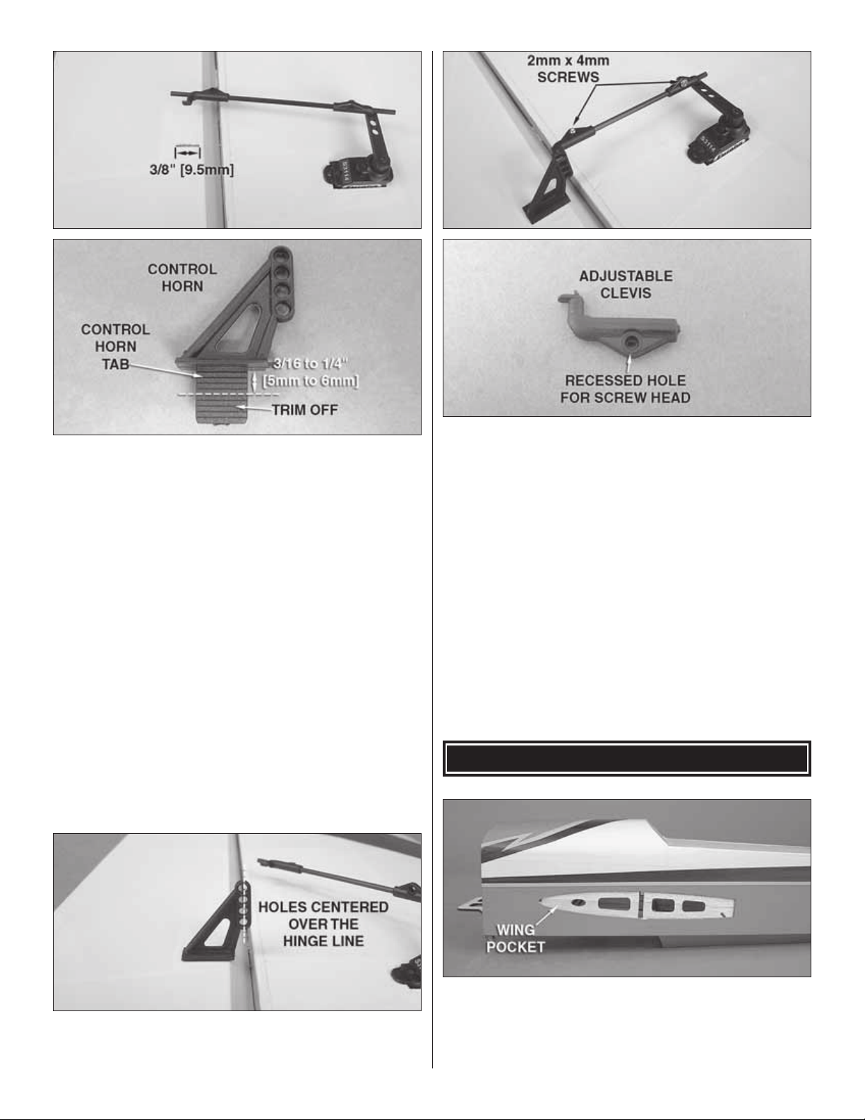
❏ 10. Locate the aileron double rib that has a rectangular
mounting block at the LE. Using the position of the pushrods
as a guide, cut a slot 3/8" [9.5mm] long perpendicular to the
hinge line just behind the bevel of the LE of aileron for each
control horn in the center of the mounting block. The slot
only needs to be wide enough to accommodate the thickness
of the control horn tab on the control horn (approximately
1/16" [1.6mm] thick). Do not cut all the way through the
ailerons! 3/16" to 1/4" [5mm to 6mm] deep is suffi cient. Trim
the control horn backplate tabs shorter so that the control
horns sit fl at in the slots you made.
❏ 12. Use the position of the control horn to adjust the length
of the pushrods as needed. Remove the servo arms from
the aileron servos. Connect the other adjustable clevises on
the aileron pushrods to the control horns and reattach the
servo arms. Fine tune the length of the pushrods inside the
clevises so that the ailerons are in the neutral position. Lock
the clevises onto the pushrods by threading a 2mm x 4mm
screw into each clevis scre w hole . The screw head should fi t
into the recessed hole in the adjustable clevises as shown
(installing the screws in the wrong direction may not properly
tighten the clevises onto the pushrods). The e xcess rod ends
can be cut away.
INST ALL THE WING P ANELS
❏ 11. Confi rm that the holes in the control horn are centered
over the hinge line. When satisfi ed, coat the backplate tabs
with medium CA and press them into the slots.
❏ 1. Trim the covering from the wing pockets in the fuse.
For the best results, work slowly and use a new hobby knife
blade for this step . Be careful not to cut into the fuse sides. On
the wing panels, trim the covering that overlaps onto the wing
panel root ribs.
9
 Loading...