

Great Planes GPMA1540 User Manual
WARRANTY
Great Planes
®
Model Manufacturing Co. guarantees this kit to be free from defects in both material and workmanship at the date of
purchase.This warranty does not cover any component parts damaged by use or modification. In no case shall Great Planes’liability
exceed the original cost of the purchased kit. Further, Great Planes reserves the right to change or modify this warranty without notice.
In that Great Planes has no control over the final assembly or material used for final assembly, no liability shall be assumed nor
accepted for any damage resulting from the use by the user of the final user-assemb led product.By the act of using the user-assembled
product, the user accepts all resulting liability.
If the buyer is not prepared to accept the liability associated with the use of this product, the buyer is advised to return this
kit immediately in new and unused condition to the place of purchase.
To make a warranty claim send the defective part or item to Hobby Services at the address below:
Hobby Services
3002 N. Apollo Dr., Suite 1
Champaign, IL 61822 USA
Include a letter stating your name, return shipping address, as much contact information as possible (daytime telephone number, fax
number, e-mail address), a detailed description of the problem and a photocopy of the purchase receipt. Upon receipt of the package
the problem will be evaluated as quickly as possible.
READ THROUGH THIS MANUAL BEFORE STARTING
CONSTRUCTION.IT CONT AINS IMPORTANT INSTRUCTIONS
AND WARNINGS CONCERNING THE ASSEMBLY AND
USE OF THIS MODEL.
GPMZ1540 for GPMA1540 V1.1Entire Contents © Copyright 2006
Champaign, Illinois
(217) 398-8970, Ext 5
airsupport@greatplanes.com
INSTRUCTION MANUAL
Wingspan: 41.5 in [1050mm]
Wing Area: 384 sq in [24.8dm2]
Weight: 24 – 27 oz [680 – 765g]
Wing Loading: 9.0 – 10.1 oz/sq ft [27 – 31g/dm2]
Length: 42 in [1065mm]
Radio: 4-channel with 4 micro [7g] servos and micro receiver
Motor: Brushless in-runner with gear-drive or brushless out-runner
™
2
INTRODUCTION ...............................................................2
AMA...................................................................................2
SAFETY PRECAUTIONS..................................................2
DECISIONS YOU MUST MAKE........................................3
Radio Equipment .........................................................3
Motor Recommendations............................................3
Propeller......................................................................3
Electronic Speed Control ............................................3
Battery Pack................................................................3
Required Adhesive & Building Supplies......................4
Optional Supplies & Tools ...........................................4
IMPORTANT BUILDING NOTES......................................4
ORDERING REPLACEMENT PARTS ..............................4
COMMON ABBREVIATIONS............................................5
METRIC CONVERSIONS .................................................5
METRIC/INCH RULER......................................................5
KIT INSPECTION..............................................................6
KIT CONTENTS ................................................................6
PREPARATIONS ...............................................................7
ASSEMBLE THE WING PANELS.....................................7
INST ALL THE WING P ANELS ..........................................9
ASSEMBLE THE T AIL SECTION....................................10
INSTALL THE LANDING GEAR .....................................14
MOUNT THE MOTOR......................................................14
In-runner Brushless Motor with 24mm Gear-Drive........15
Out-runner Brushless Motor......................................15
INSTALL THE RADIO & ESC .........................................16
INSTALL THE COWL, CANOPY & SPINNER................17
Apply the Decals .......................................................18
GET THE MODEL READY TO FLY .................................18
Check the Control Directions ....................................18
Set the Control Throws..............................................19
Balance the Model (C.G.)..........................................19
Balance the Model Laterally ......................................20
PREFLIGHT.....................................................................20
Identify Your Model ....................................................20
Charge the Batteries .................................................20
Balance the Propellers..............................................20
Range Check.............................................................21
MOTOR SAFETY PRECAUTIONS .................................21
AMA SAFETY CODE (excerpts)....................................21
CHECK LIST ...................................................................22
FLYING ............................................................................22
Takeoff.......................................................................22
Flight..........................................................................23
Landing......................................................................23
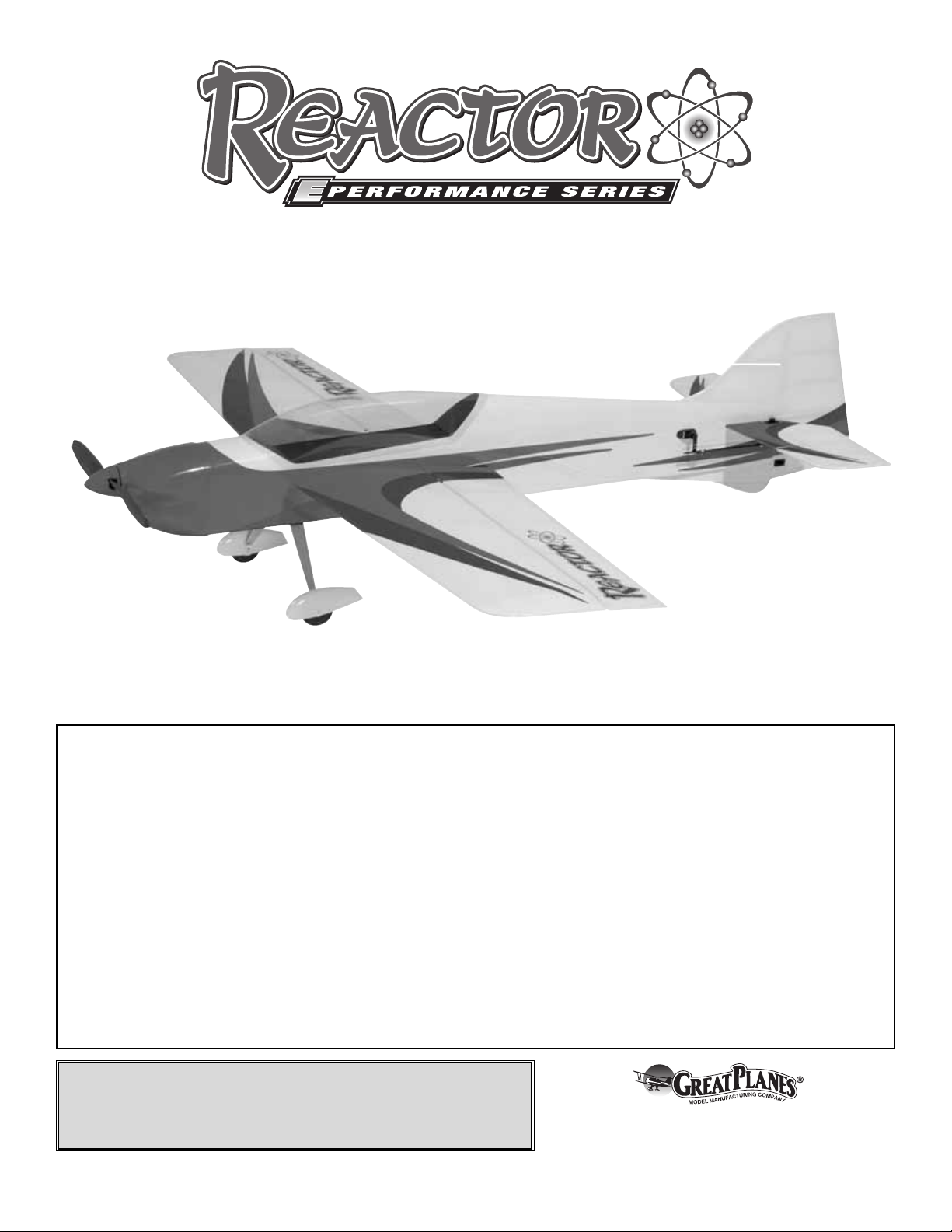
The Reactor™3D EP ARF is the first of a line of electric,
built-up, all-out performance 3D planes from Great Planes.
Using the recommended brushless power systems, the
Reactor 3D EP ARF can perform virtually any aerobatic
maneuver with authority. High capacity LiPo battery packs
will allow you the convenience of electric flying, combined
with the flight characteristics of planes much larger in size.
The sleek lines and vibrant colors of the Reactor 3D EP ARF
will surely gain attention at the flying field!
For the latest technical updates or manual corrections to the
Reactor 3D EP ARF visit the Great Planes web site at
www.greatplanes.com. Open the “Airplanes” link, then
select the Reactor 3D EP ARF. If there is new technical
information or changes to this model a “tech notice” box will
appear in the upper left corner of the page.
We urge you to join the AMA (Academy of Model Aeronautics)
and a local R/C club.The AMA is the governing body of model
aviation and membership is required to fly at AMA clubs.
Though joining the AMA provides many benefits, one of the
primary reasons to join is liability protection. Coverage is not
limited to flying at contests or on the club field. It even applies
to flying at public demonstrations and air shows. Failure to
comply with the Safety Code (excerpts printed in the back of
the manual) may endanger insurance coverage. Additionally,
training programs and instructors are available at AMA club
sites to help you get started the right way .There are over 2,500
AMA chartered clubs across the countr y. Contact the AMA at
the address or toll-free phone number below.
IMPORTANT!!! Two of the most important things you can do
to preserve the radio controlled aircraft hobby are to avoid
flying near full-scale aircraft and avoid flying near or over
groups of people.
1.Your Reactor 3D EP ARF should not be considered a toy,
but rather a sophisticated, working model that functions very
much like a full-size airplane. Because of its performance
capabilities, the Reactor 3D EP ARF, if not assembled and
operated correctly, could possibly cause injury to yourself or
spectators and damage to property.
2.Y ou must assemble the model according to the instructions.
Do not alter or modify the model, as doing so may result in
an unsafe or unflyab le model.In a fe w cases the instructions
may differ slightly from the photos. In those instances the
written instructions should be considered as correct.
3.You must take time to build straight, true and strong.
PRO TECT YOUR MODEL,Y OURSELF
& OTHERS...FOLLOW THESE
IMPORTANT SAFETY PRECAUTIONS
Academy of Model Aeronautics
5151 East Memorial Drive
Muncie, IN 47302
Tele: (800) 435-9262
Fax (765) 741-0057
Or via the Internet at:
http://www.modelaircraft.org
AMA
INTRODUCTION
TABLE OF CONTENTS

4.You must correctly install all R/C and other components so
that the model operates correctly on the ground and in the air .
5.You must check the operation of the model before every
flight to insure that all equipment is operating and that the
model has remained structurally sound. Be sure to check
clevises or other connectors often and replace them if they
show any signs of wear or fatigue.
6. If you are not an experienced pilot or have not flown this
type of model before, we recommend that you get the
assistance of an experienced pilot in your R/C club for your
first flights.If you’re not a member of a club, your local hobb y
shop has information about clubs in your area whose
membership includes experienced pilots.
7.While this kit has been flight tested to exceed normal use,
if the plane will be used for extremely high-stress flying,
such as racing, or if a motor larger than one in the
recommended range is used, the modeler is responsible for
taking steps to reinforce the high-stress points and/or
substituting hardware more suitable for the increased stress .
Remember:Take your time and follow the instructions to
end up with a well-built model that is straight and true.
This is a partial list of items required to finish the Reactor 3D
EP ARF that may require planning or decision-making before
starting to build. Order numbers are provided in parentheses.
A 4-channel radio system with four micro servos and a micro
receiver are required for this plane.The servos and receiver
shown in the manual are Futaba®S3110 micro servos and
the Futaba R114F micro receiver. Two 6" [152mm] servo
extensions, two 20" [500mm] servo extensions, and a
Y-harness are also required. Order numbers for these items
are provided below.
• (4) Futaba S3110 Micro High Torque Servo
[7.7g] (FUTM0046)
• Futaba R114F FM Micro Receiver
(Low Band – FUTL0442, High Band – FUTL0443)
• Futaba FM Single Conversion Short Crystal
(Low Band – FUTL62**, High Band – FUTL63**)
• (2) Futaba C-25 Extension Slim Wire
6" [152mm] (FUTM4506)
• (2) Futaba 20" [500mm] Heavy-Duty Servo Extension
J (FUTM4147)
The Reactor 3D EP ARF comes with mounting boxes to use
either a Great Planes Ammo™brushless in-runner motor with
gear-drive or a Great Planes RimFire™brushless out-runner
motor.The motors that have been tested and perform well in
this plane are listed below. (If using the in-runner motor with
gear-drive, be sure to install the 11T pinion gear that is
included with the gear-drive to achieve a gear ratio of 4.5:1.)
• Great Planes Ammo 24-33-4040kV Brushless In-runner
Motor (GPMG5165)
• Great Planes Gear-Drive 24mm In-runner
Motors (GPMG0505)
• Great Planes RimFire 35-30-950kV Brushless
Out-runner Motor (GPMG4590)
Note: Motors from other manufacturers may work with the
Reactor 3D EP ARF. However, the included firewall pieces
are designed to work specifically with the Great Planes
motors listed.
• If using the recommended Ammo Brushless In-runner
motor with 4.5:1 gear-drive, or the recommended
RimFire Brushless Out-runner motor, you will need a
10x4.5 Slo-Flyer Electric Propeller (GPMQ6660).
A brushless ESC (electronic speed control) is required for
this plane. We recommend using the Great Planes Silver
Series 25A Brushless ESC 5V/2A BEC (GPMM1820).
The Reactor 3D EP ARF has been flown with 11.1V LiPo
packs ranging from 1250mAh to 2100mAh. Order numbers
are provided for packs of this size. The lighter 1250mAh
pack is suggested for maximum performance.
Battery Pack
Electronic Speed Control
Propeller
Motor Recommendations
Radio Equipment
DECISIONS YOU MUST MAKE
We, as the kit manuf acturer, provide you with a top quality ,
thoroughly tested kit and instructions, but ultimately the
quality and flyability of your finished model depends on
how you build it; therefore, we cannot in any way
guarantee the performance of your completed model, and
no representations are expressed or implied as to the
performance or safety of your completed model.
3

• Great Planes LiPo 1250mAh 11.1V 20C Discharge
w/Balance (GPMP0609)
• Great Planes LiPo 1500mAh 11.1V 20C Discharge
w/Balance (GPMP0613)
• Great Planes LiPo 2100mAh 11.1V 20C Discharge
w/Balance (GPMP0617)
Note: Do not use Great Planes LiPo 1500mAh 11.1V 3S 8C
Discharge (GPMP0831).This battery pack is not capable of
supporting the current draw of the recommended
power systems.
This is the list of adhesive and building supplies required to
finish the Reactor 3D EP ARF. Order numbers are provided
in parentheses.
❏ 1/2 oz. [15g] Thin Pro
™
CA (GPMR6001)
❏ 1/2 oz. [15g] Medium Pro CA+ (GPMR6007)
❏ Pro 30-minute epoxy (GPMR6047)
❏ Denatured alcohol
❏ Drill bits: 5/64" [2mm], #54 (.0550")
❏ #1 Hobby knife (HCAR0105)
❏ #11 Blades (5-pack, HCAR0211)
❏ Hobbico
®
steel T-pins 1" [25mm] (100, HCAR5100)
Here is a list of optional supplies and tools mentioned in the
manual that will help you build the Reactor 3D EP ARF.
❏ 1" [25mm] Double-sided foam mounting
tape (GPMQ4442)
❏ 21st Century
®
sealing iron (COVR2700)
❏ 21st Century iron cover (COVR2702)
❏ 2 oz. [57g] Spray CA activator (GPMR6035)
❏ 4 oz. [113g] Aerosol CA activator (GPMR634)
❏ CA applicator tips (HCAR3780)
❏ CA debonder (GPMR6039)
❏ Epoxy brushes (6, GPMR8060)
❏ Mixing sticks (50, GPMR8055)
❏ Mixing cups (GPMR8056)
❏ Hobbico Duster
™
can of compressed air (HCAR5500)
❏ K & S #801 Kevlar
®
thread (for stab
alignment, K+SR4575)
❏ Panel line pen (TOPQ2510)
❏ Rotary tool such as Dremel
®
❏ AccuThrow
™
deflection gauge (GPMR2405)
❏ Hobbico flexible 18" ruler stainless steel (HCAR0460)
• When you see the term
test fit
in the instructions, it
means that you should first position the part on the
assembly without using any glue, then slightly modify or
custom fit
the part as necessar y for the best fit.
• Whenever the term
glue
is written you should rely upon
your experience to decide what type of glue to use.When a
specific type of adhesive works best for that step, the
instructions will make a recommendation.
• Whenever just
epoxy
is specified you may use either
30-minute (or 45-minute) epoxy or 6-minute epoxy. When
30-minute epoxy is specified it is highly recommended that
you use only 30-minute (or 45-minute) epoxy, because you
will need the working time and/or the additional strength.
•
Photos
and
sketches
are placed before the step they
refer to. Frequently you can study photos in following steps
to get another view of the same parts.
• The stabilizer and wing incidences and engine thrust
angles have been factory-built into this model. However,
some technically-minded modelers may wish to check these
measurements anyway.To view this information visit the web
site at www.greatplanes.com and click on “Technical Data.”
Due to manufacturing tolerances which will have little or no
effect on the way your model will fly, please expect slight
deviations between your model and the published values.
Replacement parts for the Great Planes Reactor 3D EP
ARF are available using the order numbers in the
Replacement Parts List that follows. The fastest, most
economical service can be provided by your hobby dealer or
mail-order company.
To locate a hobby dealer, visit the Hobbico web site at
www.hobbico.com. Choose “Where to Buy” at the bottom
of the menu on the left side of the page. Follow the
instructions provided on the page to locate a U.S., Canadian
or International dealer.
Parts may also be ordered directly from Hobby Services by
calling (217) 398-0007, or via facsimile at (217) 398-7721,
but full retail prices and shipping and handling charges will
apply. Illinois and Nevada residents will also be charged
sales tax. If order ing via fax, include a Visa®or MasterCard
®
number and expiration date for payment.
Mail parts orders and payments by personal check to:
Hobby Services
3002 N. Apollo Drive, Suite 1
Champaign, IL 61822
ORDERING REPLACEMENT PARTS
IMPORTANT BUILDING NOTES
Optional Supplies & Tools
Required Adhesive & Building Supplies
4
Be certain to specify the order number exactly as listed in
the Replacement Parts List. Payment by credit card or
personal check only; no C.O.D.
If additional assistance is required for any reason contact Product
Support by e-mail at productsupport@greatplanes.com,
or by telephone at (217) 398-8970.
Description How to Purchase
Missing pieces Contact Product Support
Instruction manual Contact Product Support
Full-size plans Not available
Kit parts listed below Hobby Supplier
Replacement Parts List
GPMA2935 ..........Wing Kit
GPMA2936 ..........Fuse Kit
GPMA2937 ..........Tail Set
GPMA2938 ..........Cowl
GPMA2939 ..........Canopy
GPMA2940 ..........Landing Gear
GPMA2941 ..........Wheel Pants
GPMA2942 ..........Hardware Set
GPMA2943 ..........Decal Sheet
Fuse = Fuselage
Stab = Horizontal Stabilizer
Fin = Ver tical Fin
LE = Leading Edge
TE = Trailing Edge
LG = Landing Gear
Ply = Plywood
" = Inches
mm = Millimeters
ESC = Electronic Speed Control
SHCS = Socket Head Cap Screw
1" = 25.4mm (conversion factor)
METRIC CONVERSIONS
COMMON ABBREVIATIONS
5
1/64" = .4mm
1/32" = .8mm
1/16" = 1.6mm
3/32" = 2.4mm
1/8" = 3.2mm
5/32" = 4.0mm
3/16" = 4.8mm
1/4" = 6.4mm
3/8" = 9.5mm
1/2" = 12.7mm
5/8" = 15.9mm
3/4" = 19.0mm
1" = 25.4mm
2" = 50.8mm
3" = 76.2mm
6" = 152.4mm
12" = 304.8mm
18" = 457.2mm
21" = 533.4mm
24" = 609.6mm
30" = 762.0mm
36" = 914.4mm
6
Before starting to build, take an inventory of this kit to make sure it is complete, and inspect the parts to make sure they
are of acceptable quality. If any parts are missing or are not of acceptable quality , or if y ou need assistance with assemb ly,
contact Product Support. When repor ting defective or missing parts, use the part names exactly as they are written in
the Kit Contents list.
Great Planes Product Support
3002 N. Apollo Drive, Suite 1
Champaign, IL 61822
Telephone: (217) 398-8970, ext. 5
Fax: (217) 398-7721
E-mail: airsupport@greatplanes.com
KIT INSPECTION
(1) Battery Hatch
(1) Elevator Joiner Wire
(1) 1-1/2" [38mm] Spinner
(1) In-runner Motor Mounting Box
(1) Out-runner Motor Mounting Box
(2) Wing Alignment Jigs
(1) Adhesive-backed Hook and Loop Material
(8) Adjustable Clevises
(4) Control Horns
(2) Control Horn Backplates
(12)Double-sided Servo Arms
(2) 2 x 85mm Carbon Pushrods
(2) 2 x 150mm Carbon Pushrods
(2) 2 x 20mm Machine Screws
(4) 2mm Flat Washers
(2) 2mm Nuts
(2) 3 x 6mm SHCS
(4) 3mm Flat Washers
(6) Magnets
Kit Contents (Not Photographed)
KIT CONTENTS
1
10
6
3
4
5
5
2
8
9
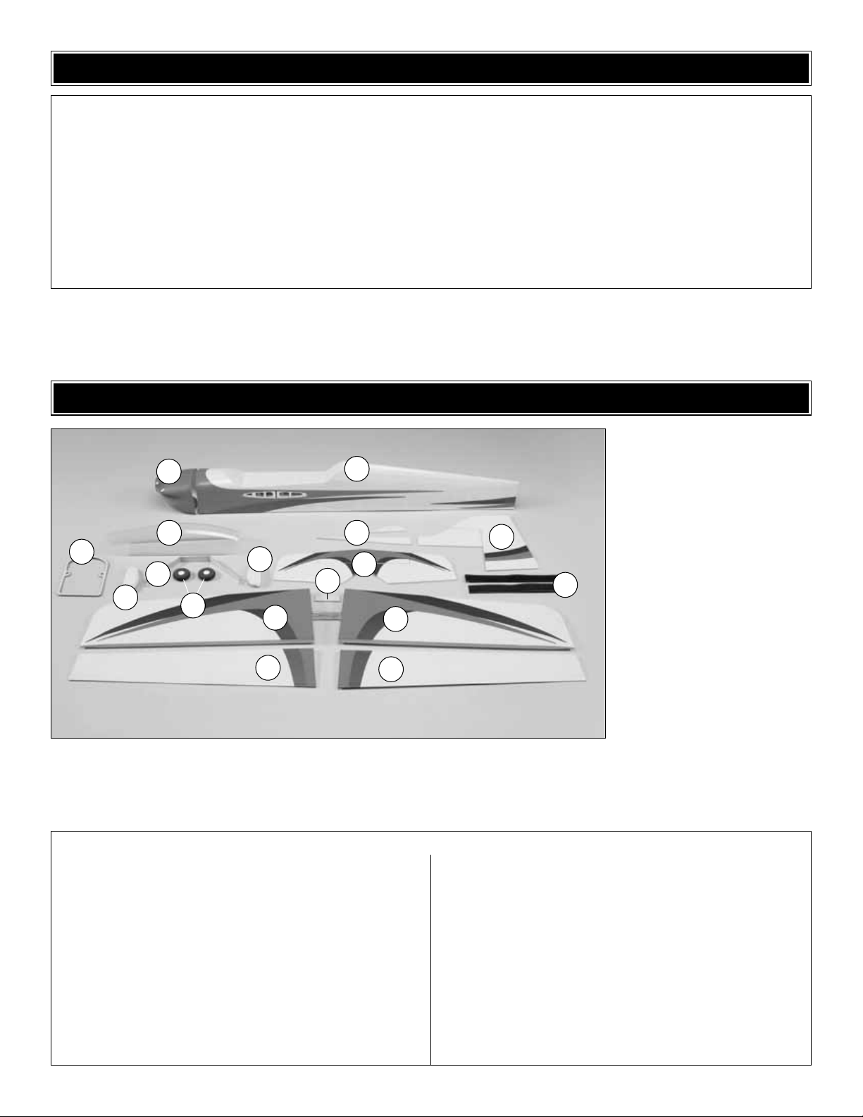
Kit Contents
1. Cowl
2. Fuselage
3. Canopy
4. Cowl Ring
5. Wheel Pants (L&R)
6. Landing Gear
7. Wheels (2)
8. Tail Skid Parts
9. Horizontal Stabilizer &
Elevator Halves
10. Vertical Fin & Rudder
11. Balsa Spar Doubler
12. Left Wing Panel
w/Center Spar
13. Right Wing Panel
w/Center Spar
14. Left Aileron
15. Right Aileron
16. Hook & Loop Material
7
11
12
14
15
16
13
❏ 1. If you have not done so already, remove the major
parts of the kit from the box and inspect them for damage.If
any parts are damaged or missing, contact Product Support
at the address or telephone number listed in the
“Kit
Inspection”
section on page 6. Important! Save the bag
that the fuselage is packaged in for a building step later
in this manual.
❏ 2. Remove the tape and separate all the control surfaces.
Use a covering iron with a covering sock on medium heat to
tighten the covering if necessary.Apply pressure over sheeted
areas to thoroughly bond the covering to the wood.
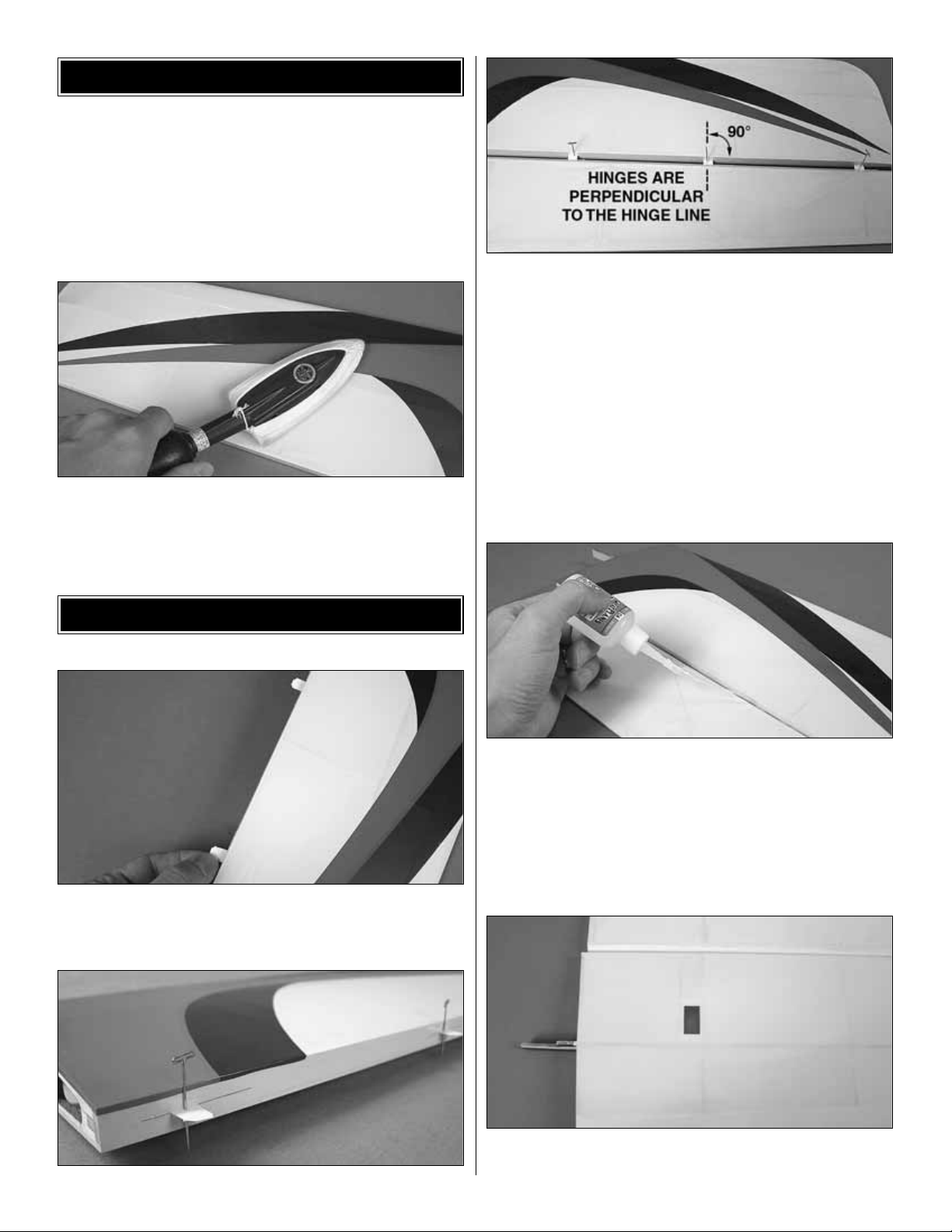
❏ 1. Test fit the pre-cut CA hinges into the slots in the
ailerons and wing panels. If any are difficult to install, use
a hobby knife in the slot to slightly enlarge it.
❏ 2. Insert the CA hinges halfway into the slots in the wing
panels. Push small T-pins through the middle of the hinges
to keep them centered. Insert the ailerons onto the other
ends of the hinges. Align the outer tips of the ailerons flush
with the wing tips.Pull the ailerons away from the panels far
enough to confirm that the hinges remained perpendicular
with the hinge line. If not, use a hobby knife or small
screwdriver to nudge them straight.
❏ 3. When satisfied, push the ailerons up against the wing
panels and carefully remove the T-pins. Use thin CA glue to
secure the ailerons by applying 3 to 4 drops onto both sides
of each hinge.
❏ 4. Trim the covering from the aileron servo bays on the
underside of the wing panels.
ASSEMBLE THE WING P ANELS
PREPARATIONS
7
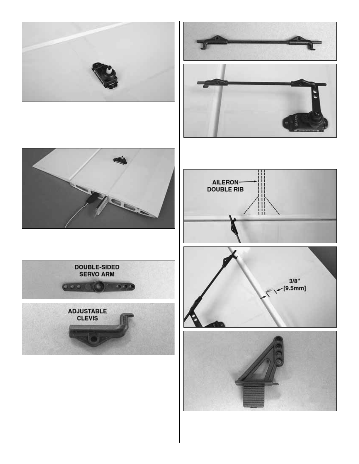
❏ 5.Insert the servo leads into the servo bays and pull them
through the wing ribs. Glue the aileron servos into the servo
bays using epoxy or CA glue. After the glue has cured,
confirm that the servos are properly secured to the wings
and reinforce with extra glue if necessary.
❏ 6. Attach a 6" [152mm] servo extension to each aileron
servo and wrap the connection with transparent tape or
heat-shrink tubing.
❏ 7. Locate two double-sided servo arms that fit the output
splines of your aileron servos and four adjustable clevises.
❏ 8. Temporarily connect your aileron servos and battery
pack to your radio and center the servos and trim levers on
the transmitter. Test fit the double-sided servo arms
perpendicular to the servo case. If the servo arm does not fit
onto the servo spline at a 90° angle to the case, remove it
from the servo and rotate it 180°. Decide which way fits best
(closest to perpendicular) and cut off the arm that isn’t used.
Be sure to make a left and right servo arm.
❏ 9. Fit two adjustable clevises onto both 2 x 85mm aileron
pushrods.Push one of the clevises from each pushrod into
the outer holes of the servo arms
❏ 10.Locate the aileron double rib that has triangle blocking
at the LE. Use a hobby knife to cut a slot 3/8" [9.5mm] long
just behind the bevel of the LE of aileron for each control
horn in the center of the double rib. The slot only needs to
8
 Loading...