

Great Planes GPMA1475 User Manual
WARRANTY
Great Planes®Model Manufacturing Co. guarantees this kit to be free from defects in both material and workmanship at the date of purchase. This warranty
does not cover any component parts damaged by use or modification. In no case shall Great Planes’ liability exceed the original cost of the purchased kit.
Further, Great Planes reserves the right to change or modify this warranty without notice.
In that Great Planes has no control over the final assembly or material used for final assemb ly, no liability shall be assumed nor accepted for any damage resulting
from the use by the user of the final user-assembled product.By the act of using the user-assembled product, the user accepts all resulting liability.
If the buyer is not prepared to accept the liability associated with the use of this product,the buyer is advised to return this kit immediatel y in new and
unused condition to the place of purchase.
To make a warranty claim send the defective part or item to Hobby Services at the address below:
Hobby Services
3002 N. Apollo Dr., Suite 1
Champaign, IL 61822
USA
Include a letter stating your name, return shipping address, as much contact information as possible (daytime telephone number, fax number, e-mail address), a
detailed description of the problem and a photocopy of the purchase receipt. Upon receipt of the package the problem will be eva luated as quickly as possible.
READ THROUGH THIS MANUAL BEFORE STARTING
CONSTRUCTION.IT CONT AINS IMPORTANT INSTRUCTIONS
AND WARNINGS CONCERNING THE ASSEMBLY AND
USE OF THIS MODEL.
GPMZ0287 for GPMA1475 V1.0 Entire Contents © Copyright 2005
Champaign, IL
(217) 398-8970, Ext. 5
airsupport@greatplanes.com
INSTRUCTION MANUAL
Wingspan: 38-1/2 in [975mm]
Wing Area: 264 sq in [17dm
2
]
Weight: 2.5 – 3 lb [1130 –1360g]
Wing Loading: 22 – 26 oz/sq ft [70 – 80g/dm
2
]
Length: 34 in [865mm]
Radio: 3-channel
Engine: .15 – .25 cu in [2.5 – 4cc] two-stroke,
.30 cu in [5cc] four-stroke

INTRODUCTION................................................................2
SAFETY PRECAUTIONS..................................................2
ADDITIONAL ITEMS REQUIRED.....................................3
Hardware & Accessories .............................................3
Adhesives & Building Supplies....................................3
Optional Supplies & Tools ............................................3
IMPORTANT BUILDING NOTES.......................................3
COMMON ABBREVIATIONS ............................................4
ORDERING REPLACEMENT PARTS ...............................4
KIT CONTENTS .................................................................5
PREPARATIONS................................................................6
BUILD THE WING..............................................................6
Install the Ailerons .......................................................6
Join the Wing...............................................................6
Install the Aileron Servo & Pushrods...........................8
Install the Belly Pan.....................................................9
BUILD THE FUSELAGE....................................................9
Install the Horizontal Stabilizer, Elevator & Vertical Fin.....9
Install Elevator Pushrods & Servo.............................10
Install the Engine, Fuel Tank & Throttle Ser vo ..........11
Install the Cowl, Prop & Spinner................................13
Install the Receiver & Battery....................................13
Finishing Touches ......................................................14
GET THE MODEL READY TO FLY..................................14
Check the Control Directions.....................................14
Set the Control Throws..............................................14
Balance the Model (C.G.)..........................................15
Balance the Model Laterally......................................16
PREFLIGHT.....................................................................16
Identify Your Model.....................................................16
Charge the Batteries ..................................................16
Balance the Propellers...............................................16
Ground Check............................................................16
Range Check.............................................................16
ENGINE SAFETY PRECAUTIONS.................................17
AMA SAFETY CODE (excerpts)....................................17
CHECK LIST ....................................................................17
FLYING.............................................................................18
Mount the Wing to the Fuselage................................18
Fuel Mixture Adjustments..........................................18
Hand Launching.........................................................18
Flight..........................................................................18
Landing......................................................................19
The Great Planes 1/12-scale Combat P-51 ARF is a great
flying model suitable for sport flying or Combat Class
#2610. Whether you are a competitor or just want a great
looking and great flying P-51, this 1/12-scale Combat P-51
ARF will become a favorite.
For the latest technical updates or manual corrections to the
Combat P-51 ARF visit the Great Planes web site at
www.greatplanes.com
. Open the “Airplanes” link, then
select the Combat P-51 ARF. If there is new technical
information or changes to this model a “tech notice”box will
appear in the upper left corner of the page.
1.Your Combat P-51 ARF should not be considered a toy,
but rather a sophisticated, working model that functions
very much like a full-size airplane. Because of its
performance capabilities, the Combat P-51 ARF, if not
assembled and operated correctly, could possibly cause
injury to yourself or spectators and damage to property.
2. You must assemble the model according to the
instructions. Do not alter or modify the model, as doing so
may result in an unsafe or unflyable model. In a few cases
the instructions may differ slightly from the photos.In those
instances the written instructions should be considered
as correct.
3.You must take time to build straight, true and strong.
4. You must use an R/C radio system that is in first-class
condition, and a correctly sized engine and components
(fuel tank, wheels, etc.) throughout the building process.
5.You must correctly install all R/C and other components
so that the model operates correctly on the ground and in
the air.
6.You must check the operation of the model before every
flight to insure that all equipment is operating and that the
model has remained structurally sound. Be sure to check
clevises or other connectors often and replace them if they
show any signs of wear or fatigue.
7. If you are not already an experienced R/C pilot, you
should fly the model only with the help of a competent,
experienced R/C pilot.
8.While this kit has been flight tested to exceed normal use,
if the plane will be used for extremely high stress flying,
such as racing, the modeler is responsible for taking steps
to reinforce the high stress points.
9. WARNING: The cowl in this kit is made of fiberglass, the
fibers of which may cause eye, skin and respiratory tract
irritation. Never blow into the part to remove fiberglass dust,
as the dust will blow back into your eyes. Always wear
safety goggles, a particle mask and rubber gloves when
grinding, drilling and sanding fiberglass parts. Vacuum the
parts and the work area thoroughly after working with
fiberglass parts.
PRO TECT YOUR MODEL,YOURSELF
& OTHERS...FOLLOW THESE
IMPORTANT SAFETY PRECAUTIONS
INTRODUCTION
TABLE OF CONTENTS
2
Remember: Take your time and follow the instructions to
end up with a well-built model that is straight and true.
If you have not flown this type of model before, we
recommend that you get the assistance of an experienced
pilot in your R/C club for your first flights. If you’re not a
member of a club, your local hobby shop has information
about clubs in your area whose membership includes
experienced pilots.
In addition to joining an R/C club, we strongly recommend y ou
join the AMA (Academy of Model Aeronautics). AMA
membership is required to fly at AMA sanctioned clubs.There
are over 2,500 AMA chartered clubs across the country.
Among other benefits, the AMA provides insurance to its
members who fly at sanctioned sites and events. Additionally,
training programs and instructors are available at AMA club
sites to help you get started the right way. Contact the AMA at
the address or toll-free phone number below.
This is the list of hardware and accessories required to
finish the Combat P-51 ARF. Order numbers are provided
in parentheses.
❏ 3-Channel radio
❏ 3-Channel (or greater) receiver
❏ (3) Micro servos with 34 oz-in of torque
❏ 12" [305mm] Servo extension
❏ Switch harness
❏ 500mAh Battery
❏ .15 – .25 cu in [2.5 – 4cc] Two-stroke or .30 cu in [5cc]
four-stroke engine
❏ Propellers suitable for your engine.
In addition to common household tools and hobby tools, this
is the “short list” of the most important items required to
build the Combat P-51 ARF.
Great Planes Pro™CA and
Epoxy glue are recommended.
❏ 1/2 oz. [15g] Thin Pro CA (GPMR6001)
❏ 1/2 oz. [15g] Medium Pro CA+ (GPMR6007)
❏ Pro 30-minute epoxy (GPMR6047)
❏ Pro 6-minute epoxy (GPMR6045)
❏ 4-40 Tap and drill set (GPMR8101)
❏ #1 Hobby knife (HCAR0105)
❏ #11 Blades (5-pack, HCAR0211)
❏ 2 oz. [57g] Spray CA activator (GPMR6035)
❏ R/C-56 Canopy glue (JOZR5007)
❏ CA applicator tips (HCAR3780)
Here is a list of optional tools mentioned in the manual that
will help you build the Combat P-51 ARF.
❏ Epoxy brushes (6, GPMR8060)
❏ Mixing sticks (50, GPMR8055)
❏ Mixing cups (GPMR8056)
❏ Builder’s Tr iangle Set (HCAR0480)
❏ Curved-tip canopy scissors for trimming plastic parts
(HCAR0667)
❏ Masking tape (TOPR8018)
❏ Denatured alcohol (for epoxy clean up)
❏ Switch & Charge Jack Mounting set (GPMM1000)
❏ Rotary tool such as Dremel
®
Moto-Tool
®
❏ Rotary tool reinforced cut-off wheel (GPMR8200)
❏ Servo horn drill (HCAR0698)
❏ Hobby Heat
™
micro torch (HCAR0750)
❏ Dead Center
™
Engine Mount Hole Locator (GPMR8130)
❏ AccuThrow
™
Deflection Gauge (GPMR2405)
❏ CG Machine
™
(GPMR2400)
❏ Precision Magnetic Prop Balancer
™
(TOPQ5700)
• When you see the term
test fit
in the instructions, it
means that you should first position the part on the
assembly without using any glue, then slightly modify or
custom fit
the part as necessar y for the best fit.
• Whenever the term
glue
is written you should rely upon
your experience to decide what type of glue to use.When a
specific type of adhesive works best for that step, the
instructions will make a recommendation.
IMPORTANT BUILDING NOTES
Optional Supplies & Tools
Adhesives & Building Supplies
Hardware & Accessories
ADDITIONAL ITEMS REQUIRED
Academy of Model Aeronautics
5151 East Memorial Drive
Muncie, IN 47302
Tele: (800) 435-9262
Fax (765) 741-0057
Or via the Internet at:
http://www.modelaircraft.org
We, as the kit manufacturer, provide you with a top
quality, thoroughly tested kit and instructions, but
ultimately the quality and flyability of your finished model
depends on how you build it;therefore, we cannot in any
way guarantee the performance of your completed
model, and no representations are expressed or implied
as to the performance or safety of your completed model.
3
• Whenever just
epoxy
is specified you may use
either
30-minute (or 45-minute) epoxy or6-minute epoxy. When
30-minute epoxy is specified it is highly recommended that
you use only 30-minute (or 45-minute) epoxy, because you
will need the working time and/or the additional strength.
•
Photos
and
sketches
are placed before the step they
refer to. Frequently you can study photos in following steps
to get another view of the same parts.
Fuse = Fuselage
Stab = Horizontal Stabilizer
Fin = Vertical Fin
LE = Leading Edge
TE = Trailing Edge
LG = Landing Gear
" = Inches
mm = millimeters
COMMON ABBREVIATIONS
4
Replacement parts for the Great Planes Combat P-51 ARF are available using the order numbers in the
Replacement Parts List that follo ws .The fastest, most economical service can be provided by your hobb y dealer or mailorder company. Parts may also be ordered directly from Hobby Services, but full retail prices and shipping and handling
charges will apply. Illinois and Nevada residents will also be charged sales tax.
To locate a hobby dealer, visit the Hobbico web site at
www.hobbico.com
. Choose “Where to Buy” at the bottom of
the menu on the left side of the page. Follow the instructions provided on the page to locate a U.S., Canadian or
International dealer. If a hobby shop is not available, replacement parts may also be ordered from Tower Hobbies at
www.towerhobbies.com
, or by calling toll free (800) 637-6050, or from Hobby Services by calling (217) 398-0007, or via
facsimile at (217) 398-7721. If ordering via fax, include a Visa®or MasterCard®number and expiration date for payment.
Mail parts orders and payments by personal check to:Hobby Services, 3002 N.Apollo Drive, Suite 1, Champaign, IL 61822.
Be certain to specify the order number exactly as listed in the Replacement Parts List. Payment by credit card or
personal check only; no C.O.D.
If additional assistance is required for any reason contact Product Support by e-mail at
productsupport@greatplanes.com
,
or by telephone (217) 398-8970.
Replacement Parts List
Or
der Number Description How to Purchase
Missing pieces.......................Contact Product Suppor t
Instruction manual.................Contact Product Support
Full-size plans........................Not available
GPMA2620 Fuselage
GPMA2621 Wing Set
GPMA2622 Tail Set
GPMA2623 Canopy
GPMA2624 Cowl
GPMA2625 Decal
ORDERING REPLACEMENT PARTS
................
Contact Your Hobby
Supplier to Purchase
These Items
5
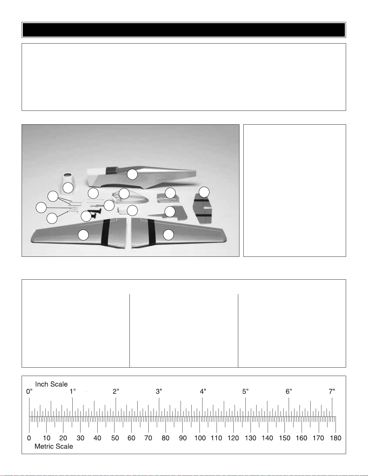
Kit Contents
1. Fuselage
2. Cowl
3. Wing Joiners (2)
4. Aileron Servo Tray
5. Elevator Joiner Wire
6. Balsa Sticks (2)
7. Wing Bolt Plates
8. Engine Mounts
9. Canopy
10. Fuel Tank
11. Belly Pan
12. Vertical Fin w/Rudder
13. Horizontal Stabilizer w/Elevators
14. Right Wing Panel w/Aileron
15. Left Wing Panel w/Aileron
Kit Contents (not photographed)
(1) 2 x 248mm Nylon Tube
(2) 2 x 114mm Threaded Pushrod Wire
(2) 1 x 508mm Wire
(4) 3 x 19mm Screws
(4) 3mm Blind Nuts
(8) 3mm Flat Washers
(2) Nylon Clevises
(2) Silicone Clevis Retainers
(2) Nylon FasLinks
(2) Screw-Lock Pushrod Connectors
(2) Knurled Nut for Screw-Lock
Pushrod Connector
(12) Hinges
(1) Nylon Control Horn
(4) 3mm Lock Washers
(2) Aileron Torque Rod Hor ns
(2) 2mm Flat Washers
(2) 1/4-20 Nylon Wing Bolts
(4) 3 x 19mm Machine Screws
(8) 2 x 19mm Washer Head Screws
(2) 2.5mm Set Screws
(1) 2.5mm Hex Wrench
(1) Elevator Joiner Wire
(1) Spinner
(1) ABS Sheet, Exhaust Stacks
Before starting to build, take an inventory of this kit to make sure it is complete, and inspect the parts to make sure they are of
acceptable quality. If any parts are missing or are not of acceptable quality, or if you need assistance with assembly, contact
Great Planes Product Support. When repor ting defective or missing parts, use the part names exactly as they are written in
the “
Kit Contents”
list on this page.
Great Planes Product Support:
Telephone: (217) 398-8970, ext. 5
Fax: (217) 398-7721
E-mail:
airsupport@greatplanes.com
KIT CONTENTS
1
2
11
6
13
14
15
10
9
To convert inches to millimeters, multiply inches by 25.4
12
3
4
5
8
7
❏ 1. If you have not done so already, remove the major
parts of the kit from the box and inspect for damage. If any
parts are damaged or missing, contact Product Suppor t at
the address or telephone number listed in the
“Kit
Contents”
section on page 5.
❏ 2. Remove the tape and separate the ailerons from the
wing and the elevators from the stab. Use a covering iron
with a covering sock on high heat to tighten the cover ing if
necessary. Apply pressure over sheeted areas to
thoroughly bond the covering to the wood.
❏ ❏ 1. Test fit the ailerons to the wing with the hinges,
making sure the aileron torque rod fits into the hole in the
aileron. Once you are satisfied with the fit, remove the
aileron from the wing. Insert the hinges into the slots in the
aileron. If the hinges did not remain centered, stick a pin
through the middle of the hinge to hold it in position.
❏ ❏ 2. Apply a small amount of 6-minute epoxy into the
hole in the aileron for the aileron torque rod.Working quickly,
install the aileron to the wing. Use rubbing alcohol to clean
any excess epoxy from the aileron and wing.
❏ ❏ 3. Remove any pins you may have inserted into the
hinges. Adjust the aileron so there is a small gap between the
LE of the aileron and the wing. The gap should be small, just
enough to see light through or to slip a piece of paper through.
❏ ❏ 4. Apply six drops of thin CA to the top and bottom of
each hinge. Do not use CA accelerator. After the CA has
fully hardened, test the hinges by pulling on the aileron.
❏ 5. Repeat steps 1-4 for the left wing panel.
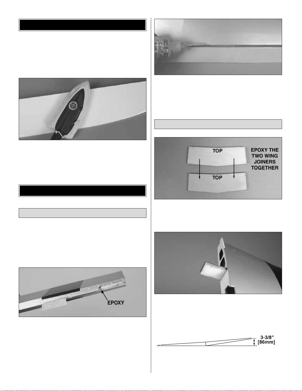
❏ 1.Locate the two hardwood wing joiners.Look closely and
you will see that the joiner has a definite angle on the top and
the bottom.The top of the joiner must be facing the top of the
wing when it is installed into the wing in the next step.
❏ 2. Test fit the joiner into both wing halves. The joiner
should fit slightly loose to allow room for glue.If the joiner is
snug, sand the face, top or bottom of the joiner as needed
to get a good fit.
❏ 3.Temporarily tape the wings together.Place the wing on
the bench. With one wing panel placed flat on the bench,
the other wing should measure approximately 3-3/8"
Join the Wing
Install the Ailerons
BUILD THE WING
PREPARATIONS
6
 Loading...