

Page 1
SPECIFICATIONS
s
®
Model Manufacturing Co.
b
p
t
w:
A
]
W
:
6lb
7
]
to
s
h
i
]
a:
d
oz/f
S
o:
chlminim
st
e
PECIFICATION
eight
Wingspan:
Wingspan
Length:
engt
Wing Loading:
Wing Loading
Wing Area:
Wing Are
WARRANTY
WARRANTY
Great Planes® Model Manufacturing Co. guarantees this kit to
Great Plane
be free from defects in both material and workmanship at the
e free from defects in both material and workmanship at the
date of purchase. This warranty does not cover any component
date of purchase. This warranty does not cover any component
parts damaged by use or modification. In no case shall Great
arts damaged by use or modification. In no case shall Great
Planes’ liability exceed the original cost of the purchased kit.
Planes’ liability exceed the original cost of the purchased kit.
Further, Great Planes reserves the right to change or modify this
urther, Great Planes reserves the right to change or modify this
warranty without notice.
warranty without notice.
In that Great Planes has no control over the final assembly or
In that Great Planes has no control over the final assembly or
material used for final assembly, no liability shall be assumed nor
material used for final assembly, no liability shall be assumed nor
accepted for any damage resulting from the use by the user of
the final user-assembled product. By the act of using the
user-assembled product, the user accepts all resulting liability.
If the buyer is not prepared to accept the liability associated
with the use of this product, the buyer is advised to return
85 in [2160mm]
85 in
62 in [1575mm]
29– 33 oz/ft
116 8 i n
16mm
2
[75.3 dm2]
75.3
mm
2
[88– 101 g/dm2]
dm
guarantees this kit to
Weight:
Radio: 5-channel minimum
Engine: 1.8 - 2 cu in [30 - 35cc] two-stroke gasoline engine
Engine:1.8 - 2 cu in [30 - 35cc] two-
Motor:
INSTRUCTION MANUAL
14.5 –16 . 5 lb [ 6570 – 7480 g]
.
1
Great Planes RimFire 1.60 (63-62-250) Outrunner Brushles
Great Planes RimFire 1.60 (63-62-250) Outrunner Brushless
this kit immediately in new and unused condition to the
his kit immediately in new and unused condition to the
place of purchase.
lace of purchase.
To make a warranty claim send the defective part or item to
o make a warranty claim send the defective part or item to
Hobby Services at the address belo
Hobby Services at the address below:
3002 N. Apollo Dr. Suite 1
002 N. Apollo Dr. Suite 1
Champaign IL 61822 USA
hampaign IL 61822 US
Include a letter stating your name, return shipping address, as
much contact information as possible (daytime telephone
number, fax number, e-mail address), a detailed description of
the problem and a photocopy of the purchase receipt. Upon
receipt of the package the problem will be evaluated as quickly
as possible.
g
gasoline engin
Hobby Services
Hobby Services
READ THROUGH THIS MANUAL BEFORE STARTING CONSTRUCTION. IT CONTAINS IMPORTANT
INSTRUCTIONS AND WARNINGS CONCERNING THE ASSEMBLY AND USE OF THIS MODEL.
© 2014 Great Planes Model Mfg. A subsidiary of Hobbico, Inc.
Champaign, Illinois
(217) 398-8970, Ext 5
airsupport@greatplanes.com
GPMA1435
Page 2

TABLE OF CONTENTS
INTRODUCTION . . . . . . . . . . . . . . . . . . . . . . . . . . . . . . . . 2
SAFETY PRECAUTIONS . . . . . . . . . . . . . . . . . . . . . . . . . 3
DECISIONS YOU MUST MAKE . . . . . . . . . . . . . . . . . . . . 3
Radio Equipment . . . . . . . . . . . . . . . . . . . . . . . . . . . . . 3
Engine Recommendations. . . . . . . . . . . . . . . . . . . . . . 4
Motor Recommendations. . . . . . . . . . . . . . . . . . . . . . . 4
Pilot . . . . . . . . . . . . . . . . . . . . . . . . . . . . . . . . . . . . . . . 4
ADDITIONAL ITEMS REQUIRED. . . . . . . . . . . . . . . . . . . 4
Required Hardware and Accessories . . . . . . . . . . . . . 4
Optional Supplies and Tools . . . . . . . . . . . . . . . . . . . . 4
IMPORTANT BUILDING NOTES . . . . . . . . . . . . . . . . . . . 4
KIT INSPECTION . . . . . . . . . . . . . . . . . . . . . . . . . . . . . . . 5
ORDERING REPLACEMENT PARTS . . . . . . . . . . . . . . . 5
KIT CONTENTS. . . . . . . . . . . . . . . . . . . . . . . . . . . . . . . . . 5
PREPARATIONS . . . . . . . . . . . . . . . . . . . . . . . . . . . . . . . . 6
ASSEMBLE THE WING . . . . . . . . . . . . . . . . . . . . . . . . . . 6
ASSEMBLE THE FUSELAGE . . . . . . . . . . . . . . . . . . . . . 9
Install the Stabilizer and Rudder . . . . . . . . . . . . . . . . 10
Install the Elevator and Rudder Servos . . . . . . . . . . . 12
Mount the Tail Wheel, Bracket and Support Wires . . 14
ELECTRIC MOTOR INSTALLATION . . . . . . . . . . . . . . . 16
IN STALL THE ENGINE, THROTTLE/CHOKE
SERVOS AND IGNITION SWITCH . . . . . . . . . . . . . . . 19
INSTALL THE COWL . . . . . . . . . . . . . . . . . . . . . . . . . . . 25
IN STALL THE WHEELS, WHEEL PANTS
AND WING STRUTS . . . . . . . . . . . . . . . . . . . . . . . . . . 28
COMPLETE THE RADIO INSTALLATION . . . . . . . . . . . 31
INSTALL THE COCKPIT, PILOT AND SPINNER . . . . . 32
APPLY THE DECALS . . . . . . . . . . . . . . . . . . . . . . . . . . . 36
GET THE MODEL READY TO FLY. . . . . . . . . . . . . . . . . 36
Check the Control Directions . . . . . . . . . . . . . . . . . . . 36
Set the Control Throws . . . . . . . . . . . . . . . . . . . . . . . 36
Balance the Model (C.G.) . . . . . . . . . . . . . . . . . . . . . 37
Balance the Model Laterally . . . . . . . . . . . . . . . . . . . 38
PREFLIGHT. . . . . . . . . . . . . . . . . . . . . . . . . . . . . . . . . . . 38
Identify Your Model . . . . . . . . . . . . . . . . . . . . . . . . . . 38
Charge the Batteries . . . . . . . . . . . . . . . . . . . . . . . . . 38
Balance Propellers. . . . . . . . . . . . . . . . . . . . . . . . . . . 38
Ground Check and Range Check . . . . . . . . . . . . . . . 38
ENGINE SAFETY PRECAUTIONS. . . . . . . . . . . . . . . . . 39
AMA SAFETY CODE. . . . . . . . . . . . . . . . . . . . . . . . . . . . 39
CHECK LIST . . . . . . . . . . . . . . . . . . . . . . . . . . . . . . . . . . 39
FLYING . . . . . . . . . . . . . . . . . . . . . . . . . . . . . . . . . . . . . . 40
Fuel Mixture Adjustments . . . . . . . . . . . . . . . . . . . . . 40
Takeoff . . . . . . . . . . . . . . . . . . . . . . . . . . . . . . . . . . . . 40
Flight . . . . . . . . . . . . . . . . . . . . . . . . . . . . . . . . . . . . . 41
Landing . . . . . . . . . . . . . . . . . . . . . . . . . . . . . . . . . . . 41
FIREWALL TEMPLATES . . . . . . . . . . . . . . . . . . . . . . . . 43
INTRODUCTION
Great Planes is very proud to bring you the Citabria. This is
a great flying model that you will enjoy and will turn heads at
the flying field. We have made a realistic airplane that has no
bad flight characteristics. We believe you will be very pleased
with the final product.
For the latest technical updates or manual corrections to
the Giant Scale Citabria ARF visit the Great Planes web site
at www.greatplanes.com. Open the “Airplanes” link, then
select the Giant Scale Citabria ARF. If there is new technical
information or changes to this model a “tech notice” box will
appear in the upper left corner of the page.
AMA
If you are not already a member of the AMA, please join! The
AMA is the governing body of model aviation and membership
provides liability insurance coverage, protects modelers’ rights
and interests and is required to fly at most R/C sites:
Academy of Model Aeronautics
5151 East Memorial Drive
Muncie, IN 47302-9252
Tele. (800) 435-9262
Fax (765) 741-0057
Or via the Internet at: http://www.modelaircraft.org
IMPORTANT!!! Two of the most important things you can
do to preserve the radio controlled aircraft hobby are to avoid
flying near full-scale aircraft and avoid flying near or over
groups of people.
IMAA
The Great Planes Giant Scale Citabria ARF is an excellent
sport-scale model and is eligible to fly in IMAA events. The
IMAA (International Miniature Aircraft Association) is an
organization that promotes non-competitive flying of giantscale models. If you plan to attend an IMAA event, obtain a
copy of the IMAA Safety Code by contacting the IMAA at
the address or telephone number below, or by logging on to
their web site at:
IMAA
205 S. Hilldale Road
Salina, KS 67401
Tele. (913) 823-5569
www.fly-imaa.org/imaa/sanction.html
Scale Competition
Though the Great Planes Citabria is an ARF and may not
have the same level of detail as an “all-out” scratch-built
competition model, it is a scale model nonetheless and is
therefore eligible to compete in the Fun Scale class in AMA
competition (we receive many favorable reports of Great
Planes ARFs in scale competition!). In Fun Scale, the “builder
2
Page 3

of the model” rule does not apply. To receive the five points for
scale documentation, the only proof required that a full size
aircraft of this type in this paint/markings scheme did exist is
a single sheet such as a kit box cover from a plastic model,
a photo, or a profile painting, etc. If the photo is in black and
white other written documentation of color must be provided.
Contact the AMA for a rule book with full details.
If you would like photos of the full-size Citabria for scale
documentation, or if you would like to study the photos to add
more scale details, photo packs are available from:
Bob’s Aircraft Documentation Tele: (714) 979-8058
3114 Yukon Ave Fax: (714) 979-7279
Costa Mesa, CA 92626 bobsairdoc.com
SAFETY PRECAUTIONS
Protect Your Model, Yourself & Others…
Follow These Important Safety Precautions
1.
Your Citabria should not be considered a toy, but rather a
sophisticated, working model that functions very much like a
full-size airplane. Because of its performance capabilities, the
Citabria, if not assembled and operated correctly, could possibly
cause injury to yourself or spectators and damage to property.
2. You must assemble the model according to the instructions.
Do not alter or modify the model, as doing so may result in an
unsafe or unflyable model. In a few cases the instructions may
differ slightly from the photos. In those instances the written
instructions should be considered as correct.
3. You must take time to build straight, true and strong.
4. You must use an R /C radio system that is in good condi tion,
a correctly sized engine, and other components as specified
in this instruction manual. All components must be correctly
installed so that the model operates correctly on the ground
and in the air. You must check the operation of the model
and all components before every flight.
5. If you are not an experienced pilot or have not flown this type
of model before, we recommend that you get the assistance
of an experienced pilot in your R/C club for your first flights.
If you’re not a member of a club, your local hobby shop has
information about clubs in your area whose membership
includes experienced pilots.
6. While this kit has been flight tested to exceed normal use,
if the plane will be used for extremely high stress flying, such
as racing, or if an engine larger than one in the recommended
range is used, the modeler is responsible for taking steps to
reinforce the high stress points and/or substituting hardware
more suitable for the increased stress.
7. WARNING: The cowl and other miscellaneous parts included
in this kit are made of fiberglass, the fibers of which may cause
eye, skin and respiratory tract irritation. Never blow into a
par t to remove fi berglass d ust, as t he dust wi ll blow back into
your eyes. Always wear safety goggles, a particle mask and
rubber gloves when grinding, drilling and sanding fiberglass
parts. Vacuum the parts and the work area thoroughly after
working with fiberglass parts.
We, as the kit manufacturer, provide you with a top quality,
thoroughly tested kit and instructions, but ultimately the
quality and fl yability of your fi nished model depends on how
you build it; therefore, we cannot in any way guarantee the
performance of your completed model, and no representations are expressed or implied as to the performance or
safety of your completed model.
NOTE: Some technically-minded modelers who wish to
check the wing, stab and motor thrust angles may do so by
visiting the web site at www.greatplanes.com and clicking
on “Technical Data.”
REMEMBER: Take your time and foll ow the instructions
to end up with a well-built model that is straight and true.
DECISIONS YOU MUST MAKE
This is a partial list of items required to finish the CITABRIA
that m ay require planning or de c ision making before starting
to build. Order numbers are provided in parentheses.
Radio Equipment
The Citabria can be flown with a minimum of a five channel radio.
For our installation we used six channels. One channel each
was used for the throttle, choke, elevator, rudder, ailerons, flaps.
Recommended servos: All control surfaces require the use
of a high-quality servo of at least 85 oz-in of torque. A servo
of 40 oz-in of torque can be used for the throttle, and choke.
❍ Control surfaces – Futaba 3305 (FUTM0045)
❍ Throttle and choke – Futaba 9001 (FUTM0075)
❍ Two 20" [500mm] Heavy-Duty Servo Extensions
(FUTM4147) for the ailerons and two 8" [200mm] Heavy
Duty Servo Extensions for the flaps.
❍ Depending on your choice of receiver and the number
of channels you will be using, you may have to use “Y”
harnesses (FUTM4135) on the aileron and flaps.
❍ 3200 mAh NiCd receiver battery or equivalent
(FUTM1285).
❍ 2 - Heavy duty switch harness (FUTM4385).
❍ 2 - Earnst Charge Receptacle (ERNM3001).
Engine Recommendations
The recommended engine size range for the Citabria is a 30 –
35cc [1.8 - 2 ci.] two-stroke gasoline engine. We used the DLE
30 engine for our model. Other engines can also be used but
you may need to make modifications for mounting those engines.
❍ J'TEC Radiowave Wrap Around Pitts Muffler DLE30
(JTCG2100)
3
Page 4

Motor Recommendations
IMPORTANT BUILDING NOTES
❍ Great Planes RimFire 1.60 63-62-250 Outrunner
Brushless (GPMG4795)
❍ Great Planes large motor mount (GMPG1260)
❍ Great Planes 80A Brushless ESC (GPMM1860)
❍ Great Planes 6mm Male/4mm Female Bullet Adapter
(GPMM3119)
❍ Two - FlightPower LiPo Pro50 4S 14.8V 5000mAh 50C
❍ Spinner Adapter Kit (GPMQ4589)
Pilot
❍ Great Planes 1/4 scale sport pilot figure (GPMQ9010)
ADDITIONAL ITEMS REQUIRED
Required Hardware and Accessories
This is the list of hardware and accessories required to finish
the CITABRIA. Order numbers are provided in parentheses.
❍ R/C foam rubber (1/4" [6mm] - HCAQ1000, or 1/2" [13mm]
- HCAQ1050)
❍ 1 oz. [30g] Thin Pro CA (GPMR6002)
❍ 1 oz. [30g] Medium Pro CA+ (GPMR6008)
❍ Pro 30-minute epoxy (GPMR6047)
❍ Pro 6-minute epoxy (GPMR6045)
❍ Silver solder w/flux (STAR2000)
❍ Hobbico Soldering Iron 60 Watt (HCAR0776)
❍ #1 Hobby knife (XACR4325)
❍ #11 blades (5-pack, XACR0211)
❍ R/C-56 canopy glue (JOZR5007)
❍ Duratrax Shoe Goo (DTXC2460) or other silicone glue
❍ Masking tape
❍ Threadlocker thread locking cement (GPMR6060)
❍ Denatured alcohol (for epoxy clean up)
❍ Rotary tool such as Dremel
❍ Rotary tool reinforced cut-off wheel (GPMR8200)
❍ Drill bits: 1/16" [1.6mm], 3/32" [2.4mm], 1/8" [3.2mm],
3/16" [4.8mm], 1/4" [6mm]
❍ One package of 3' x 1/8" I.D. Tygon fuel tubing (DUBQ0493)
❍ Fuel barbs (DUBQ0672)
Tools and Building Supplies
Here is a list of optional tools mentioned in the manual that
will help you build the Citabria.
❍ 21st Century sealing iron (COVR2700)
❍ 21st Century iron cover (COVR2702)
❍ 2 oz. [57g] spray CA activator (GPMR6035)
❍ 4 oz. [113g] aerosol CA activator (GPMR634)
❍ Epoxy brushes (6, GPMR8060)
❍ Mixing sticks (50, GPMR8055)
❍ Mixing cups (GPMR8056)
● There are three types of screws used in this kit:
Sheet Metal Screws are designated by a number and a
length. For example #6 3/4" [19mm].
This is a number six screw
that is 3/4" [19mm] long.
Machine Screws are designated by a number,
threads per inch, and a length. For example
4-40 3/4" [19mm].
This is a number four screw
that is 3/4" [19mm] long with
forty threads per inch.
Socket Head Cap Screws (SHCS) are designated by a
number, threads per inch, and a length. For example
4-40 3/4" [19mm].
This is a 4-40 SHCS that
is 3/4" [19mm] long with
forty threads per inch.
● When you see the term test fit in the instructions, it means
that you should first position the part on the assembly
without using any glue, then slightly modify or custom
fit the part as necessary for the best fit.
● Whenever the term glue is written you should rely upon
your experience to de cide what type of glue to use. When
a specific type of adhesive works best for that step, the
instructions will make a recommendation.
● Whenever just epoxy is specified you may use either
30-minute (or 45-minute) epoxy or 6-minute epox y. Whe n
30-minute epoxy is specified it is highly recommended that
you use only 30-minute (or 45-minute) epoxy, because you
will need the working time and/or the additional strength.
● Photos and sketches are placed before the step they
refer to. Frequently you can study photos in following steps
to get another view of the same parts.
● The Giant Scale Citabria is factory-covered with Top Flite
MonoKote film. Should repairs ever be required, MonoKote
can be patched with additional MonoKote purchased
separately. MonoKote is packaged in six-foot rolls, but
some hobby shops also sell it by the foot. If only a small
piece of MonoKote is needed for a minor patch, perhaps a
fellow modeler would give you some. MonoKote is applied
with a model airplane covering iron, but in an emergency
a regular iron could be used. A roll of MonoKote includes
full instructions for application. Following are the colors
used on this model and order numbers for six foot rolls.
Missile Red TOPQ0201
Jet White TOPQ0204
Black TOPQ0208
● The stabilizer and wing incidences and engine thrust
angles have been factory-built into this model. However,
some technically-minded modelers may wish to check
4
Page 5
these measurements anyway. To view this information
visit the web site at www.greatplanes.com and click on
“Technical Data.” Due to manufacturing tolerances which
will have little or no effect on the way your model will fly,
please expect slight deviations between your model and
the published values.
Illinois and Nevada residents will also be charged sales tax.
If ordering via fax, include a Visa® or MasterCard® number
and expiration date for payment.
Mail parts orders Hobby Services
and payments by 3002 N Apollo Drive, Suite 1
personal check to: Champaign IL 61822
KIT INSPECTION
Before starting to build, take an inventory of this kit to make
sure it is complete, and inspect the parts to make sure they
are of acceptable quality. If any parts are missing or are
not of acceptable quality, or if you need assistance with
assembly, contact Product Support. When reporting defective
or missing parts, use the part names exactly as they are
written in the Kit Contents list.
Great Planes Product Support
3002 N Apollo Drive, Suite 1 Ph: (217) 398-8970, ext. 5
Champaign, IL 61822 Fax: (217) 398-7721
E-mail: airsupport@greatplanes.com
ORDERING REPLACEMENT PARTS
Replacement parts for the Great Planes Citabria are available
using the order numbers in the Replacement Parts List that
follows. The fastest, most economical service can be provided
by your hobby dealer or mail-order company.
To locate a hobby dealer, visit the Great Planes web site at
www.greatplanes.com. Select “Where to Buy” in the menu
across the top of the page and follow the instructions provided
to locate a U.S., Canadian or International dealer.
Parts may also be ordered directly from Hobby Services by
calling (217) 398-0007, or via facsimile at (217) 398-7721, but
full retail prices and shipping and handling charges will apply.
Be certain to specify the order number exactly as listed in the
Replacement Parts List. Payment by credit card or personal
check only; no C.O.D.
If additional assistance is required for any reason contact
Product Support by e-mail at productsupport@greatplanes.
com, or by telephone at (217) 398-8970.
REPLACEMENT PARTS LIST
Order No. Description
GPMA4535
GPMA4536
GPMA4537
GPMA4538
GPMA4539
GPMA4540
GPMA4541
GPMA4542
GPMA4543
GPMA4544
GPMA4545
GPMA4546
GPMA4547
GPMA4548
Wing Set
Fuselage
Horizontal Stabilizer
Vertical Stabilizer
Cowl
Landing Gear
Wheel Pants
Hatch
Tailwheel Assembly
Spinner
Wing Tube
Wing Struts
Bracket Set
Decals
KIT CONTENTS
Kit Contents
2
8
9
7
10
12
13
6
11
1
3
5
4
1
15
14
5
1.
Wing Halves
2.
Fuselage
3.
Horizontal Stabilizer
4.
Fin
5.
Tailwheel Assembly
6.
Cockpit Floor
7.
Cockpit Seat Backs
8.
Spinner
9.
Fuel Tank
10.
Main Landing Gear
11.
Wheel Pants
12.
Interplane Struts
13.
Decal Sheet
14.
Wing Tube
15.
Wing Struts
Page 6
PREPARATIONS
1.
If you have not done so already, remove the major parts
❏
of the kit from the box and inspect for damage. If any parts are
damaged or missing, contact Product Support at the address or
telephone number listed in the “Kit Inspection” section on page 5.
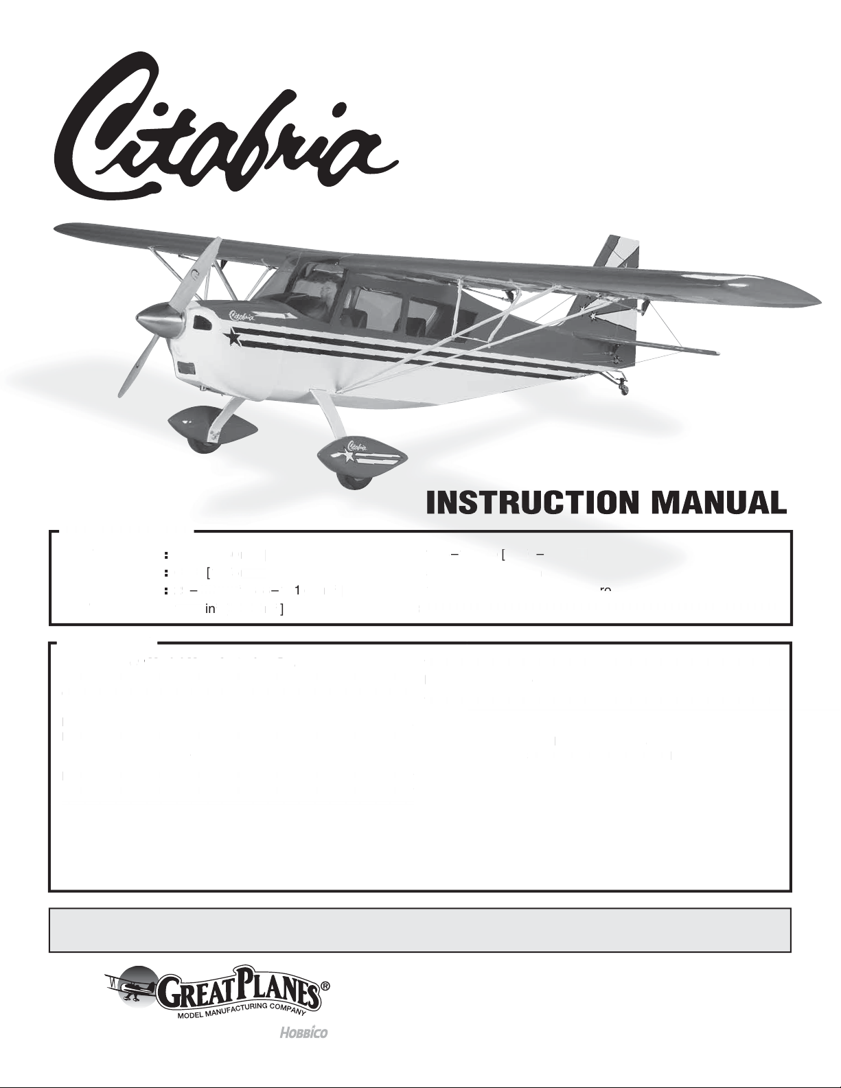
2. Use a covering iron with a covering sock on high heat
❏
to tighten the covering if necessary. Do this for all of the
components of the model. Apply pressure over sheeted areas
to thoroughly bond the covering to the wood.
4. Glue the blocks to the servo cover. Once the glue
❏ ❏
has cured, drill a 1/16" [1.6mm] hole through the cover and
into the servo mounting blocks Secure the block to the cover
with a #2 x 3/8" [#2 x 9.5mm] wood screw. Do this for both of
the servo covers.
ASSEMBLE THE WING
Note:
Throughout this instruction manual you will be instructed
to use screws to secure different parts. In all cases, whenever
a screw is threaded into wood sheeting or wood blocks we
recommend that you install the screw and then remove it.
Apply a drop of thin CA glue into the hole to harden the threads.
After the glue has hardened, re-install the screw. Following this
step will insure that you have a solid thread for your screws.
Begin with your left wing panel first so your assembly
matches the photos in the manual.
1. Install the grommets and eyelets into the servo and
❏ ❏
then attach a 20" [500mm] servo extension to your aileron
servo. Secure it with heat shrink tubing, tape or other method
for securing them together.
2. Install a 8" [200mm] servo extension to your flap
❏ ❏
servo. Secure it with heat shrink tubing, tape or other method
for securing them together.
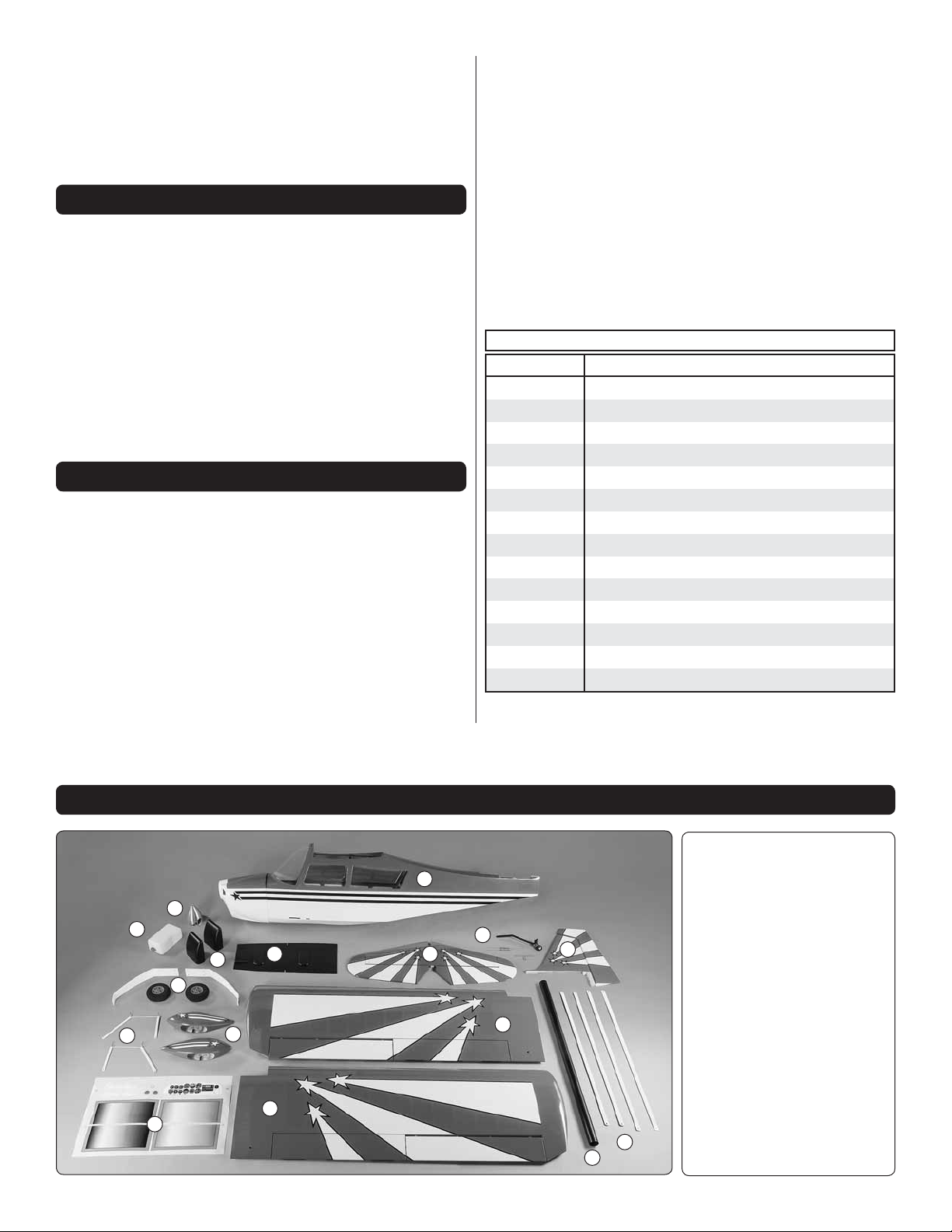
3. Remove the tape
❏ ❏
holding the servo covers
to the bottom of the wing.
Locate two 5/16" x 3/4"
x 3/4" [8mm x 19mm x
19mm] hardwood blocks.
Place your servo on the
cover, centering the servo
arm in the slot. Adjust the
positioning of the blocks for
your brand of servo.
5. If you haven’t already, center the servos and install
❏ ❏
the servo arm onto your servos. The servos require a 3/4"
[19mm] servo arm (typically the longest servo arm with your
servo). Place your servo onto the mounting blocks. Drill a
1/16" [1.6mm] hole through the servo mounting tabs into the
mounting blocks. Secure the servos to the mounting blocks
with the screws that came with your servos.
6. Inside the aileron and flap servo compartment you
❏ ❏
will find a string. Tie the string to the servo lead. The other
end of the string is taped to the root wing of the rib. Pull the
leads through the wing.
6
Page 7
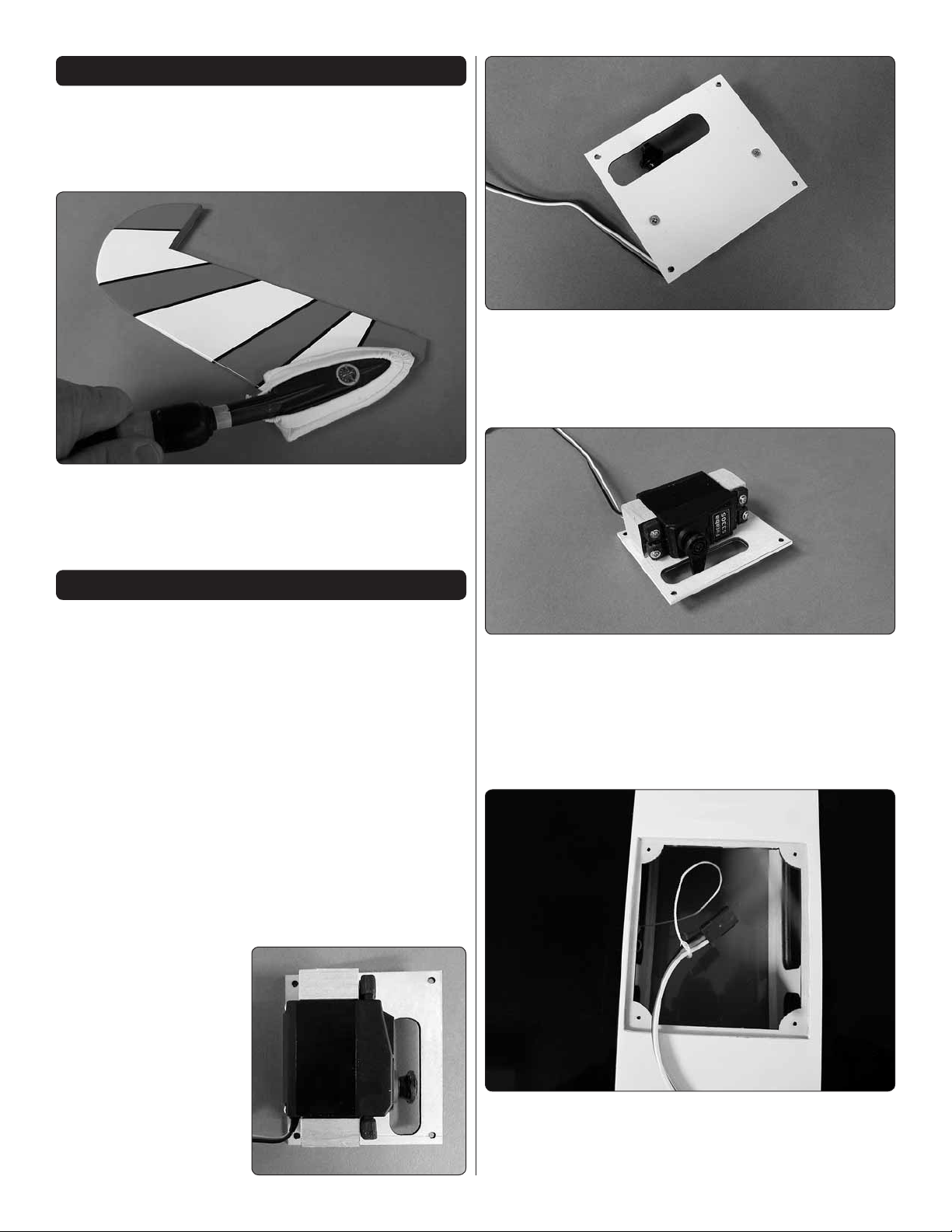
7. Install the servo cover to the wing securing them to
❏ ❏
the wing with four #2 x 3/8" [9.5mm] screws and four #2 flat
washers.
8. Tape the servo lead to the top of the wing to prevent
❏ ❏
the leads from falling back into the wing.
10. Place a black nylon control horn onto the plywood
❏ ❏
mounting plate in the aileron in line with the servo arm.
Drill a 3/32" [2.4mm] hole through each of the holes in the
control horn. Drill only through the plywood plate. Do not
drill through the top of the control surface. Mount the horn
with four #4 x 3/8" [10mm] screws.
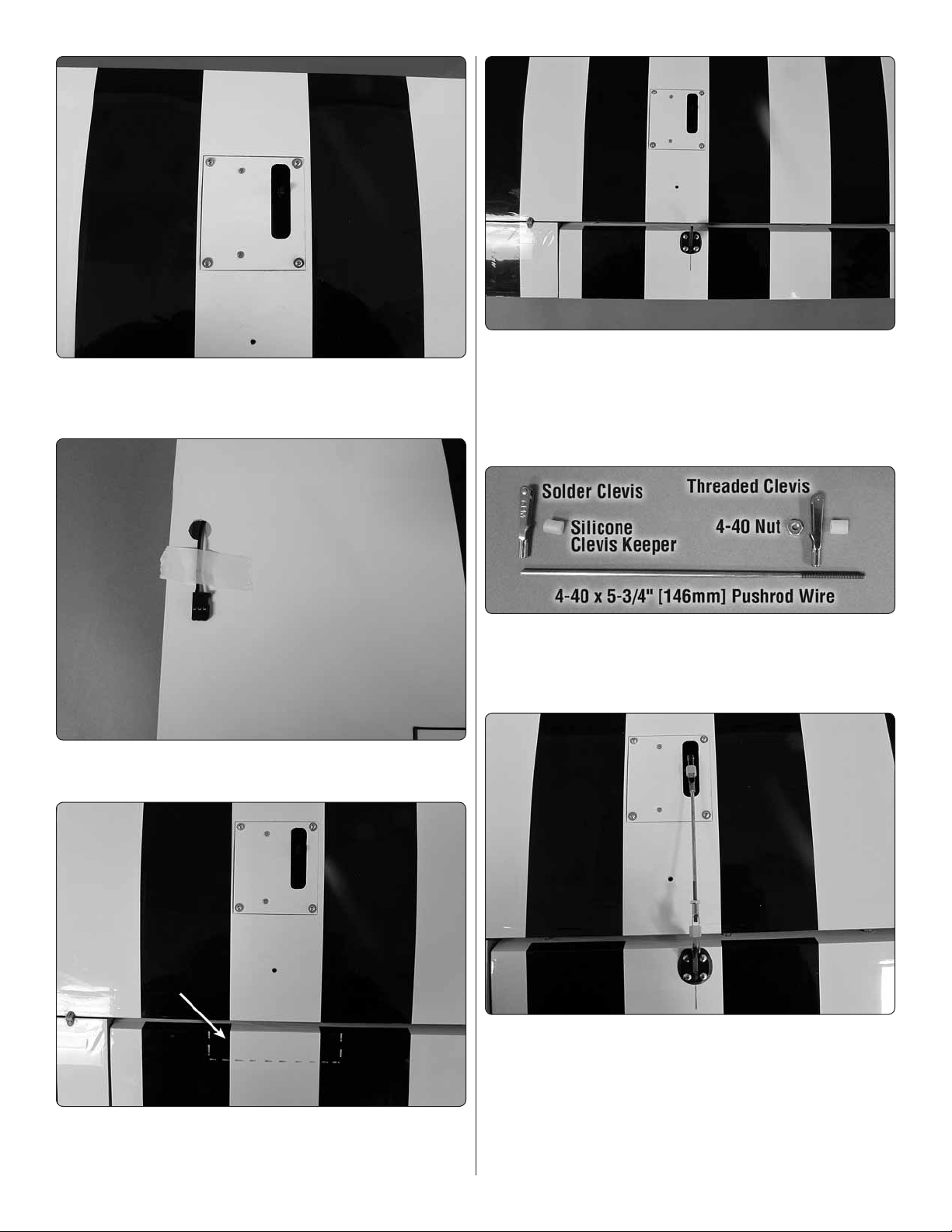
11. Each aileron and flap pushrod are made from a
❏ ❏
5-3/4" [146mm] 4-40 pushrod wire threaded on one end, a
threaded metal clevis, a 4-40 nut, a metal solder clevis and
two silicone clevis keepers.
9. Located in both the aileron and the flap is a plywood
❏ ❏
mounting plate. If you look at the control surface at a slight
angle you will be able to see the plate through the covering.
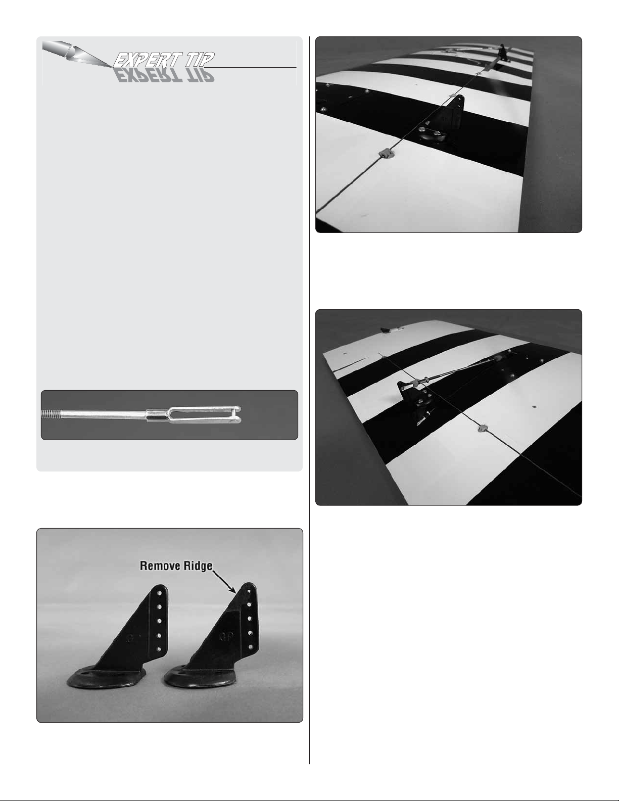
12. Screw the 4-40 nut and the threaded metal clevis
❏ ❏
onto the pushrod wire. Attach the clevis to the second hole
down on the control horn. Attach the metal solder clevis into
the outer hole of the aileron servo arm. Center the aileron
servo arm and the aileron. Mark on the pushrod wire where
to cut the wire. Remove all of the pushrod wire components.
Solder the metal solder clevis to the pushrod. If you are not
familiar with soldering, read the Expert Tip that follows.
7
Page 8
HOW TO SOLDER
1. Roughen the end of the pushrod with coarse sandpaper
where it is to be soldered. Use denatured alcohol or other
solvent to thoroughly clean the pushrod.
2. Apply a few drops of soldering fl ux to the end of the
pushrod, and then use a soldering iron or a torch to heat
it. “Tin” the heated area with silver solder by applying the
solder to the end. The heat of the pushrod should melt the
solder – not the fl ame of the torch or soldering iron – thus
allowing the solder to fl ow. The end of the wire should be
coated with solder all the way around.
3.
Place the clevis on the end of the pushrod. Add another
drop of fl ux, then heat and add solder. The same as before,
the heat of the parts being soldered should melt the solder,
thus allowing it to fl ow. Allow the joint to cool naturally
without disturbing. Avoid excess blobs, but make certain
the joint is thoroughly soldered. The solder should be shiny,
not rough. If necessary, reheat the joint and allow to cool.
4. Immediately after the solder has solidifi ed, but while it
is still hot, use a cloth to quickly wipe off the fl ux before
it hardens. Important: After the joint cools, coat the joint
with oil to prevent rust. Note: Do not use the acid fl ux that
comes with silver solder for electrical soldering.
15. Install the modified control horn to the flap. However,
❏ ❏
the flap horn is rotated 180° from the direction the aileron
horn was installed. Install the horn using the same method
used for the aileron. Make sure the base of the horn is even
with the flap leading edge.
This is what a properly soldered clevis looks like –
shiny solder with good flow, no blobs and flux removed.
13. Once the solder has cooled slide a silicone clevis
❏ ❏
keeper over each clevis. Install the pushrod wire assembly to
the aileron servo arm and aileron control horn.
14. The flap control horn needs to be modified. Trim a
❏ ❏
control horn as shown. A high speed motor tool works well
for this.
16. Screw the 4-40 nut and the threaded metal clevis
❏ ❏
onto the pushrod wire. Attach the clevis to the second hole
down on the control horn. Attach the metal solder clevis into
the outer hole of the flap servo arm. For the flap servo you
will not center the servo. Instead, make sure the flap is fully
closed to the bottom of the wing. Then position the servo arm
so that it is rotated toward the wing trailing edge. Now you can
proceed with making the pushrod wire assembly.
Mark on the pushrod wire where to cut the wire. Remove
all of the pushrod wire components. Solder the metal solder
clevis to the pushrod. Once the solder has cooled slide a
silicone clevis keeper over each clevis. Install the pushrod
wire assembly to the servo arm and control horn.
17. Repeat steps 1-16 for the right wing.
❏
8
Page 9

18. The kit includes two 5/16" x 1-5/16" [8 x 35mm] wood
❏
dowels and one 5/16" x 1-1/8" [8 x 30mm] wood dowel. Using
5 minute epoxy, glue the two 5/16" x 1-5/16" [8 x 35mm] wood
dowels into the holes in the leading edge of both wings. The
dowels should be completely seated into the hole. This will
allow approximately 5/16" [8mm] to extend out of the wing.
20. Once the glue has hardened test fit the two wing halves
❏
together by inserting the wing tube into one of the wings
and then sliding the other wing onto the tube. Once you are
satisfied they fit together well, set the wing aside and move
on to the fuselage assembly.
ASSEMBLE THE FUSELAGE
1. Remove the windshield from the front of the fuselage.
❏
It is attached to the fuselage with magnets. Pull forward on
the top of the windshield frame to release the frame from the
fuselage.
19.
Using 5 minute epoxy, glue the 5/16" x 1-1/8" [8 x 30mm]
❏
wood dowel into the hole at the trailing edge of the root rib on
either the left or right wing.
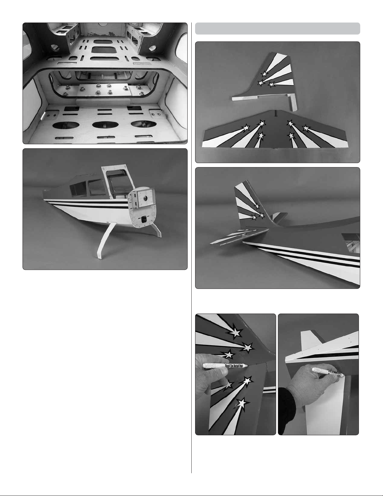
2. Install the landing gear. With the landing gear in place
❏
you will find it easier to handle the fuselage while assembling
the components. Locate the landing gear and the landing
gear doubler plate.
9
Page 10
Install the Stabilizer and Rudder
3. Slide the landing gear into the slots in both sides of the
❏
fuselage and place the aluminum doubler onto the landing
gear. Secure the doubler and the landing gear to the fuselage
with ten #6 x 3/4" [19mm] socket head cap screws, #6 lock
washers and #6 flat washers. Apply a drop of thread locker
to each of the screws. NOTE: The landing gear will have a
slight forward sweep when installed correctly.
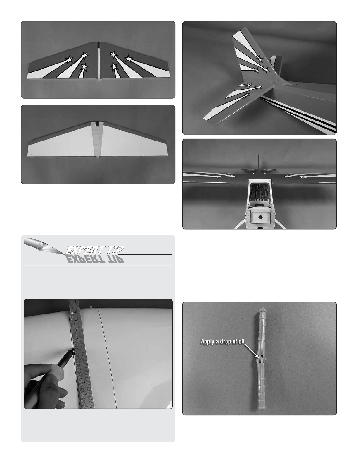
1. Locate the stabilizer and vertical fin. Test fit them in
❏
place on the back of the fuselage.
2. Use a felt tip pen to outline the fin on the top of the
❏
stabilizer and to outline the fuselage on the bottom of the
stabilizer.
10
Page 11
3. Remove the fin and stabilizer from the fuselage. Cut the
❏
covering from the stabilizer just inside of the lines you have
drawn. Be careful to only cut through the covering. DO
NOT cut the wood structure. You may find it easiest to cut
the covering away using the Expert Tip “How to Cut Covering
from Balsa”.
HOW TO CUT COVERING FROM BALSA
Use a soldering iron to cut the covering from the stab. The
tip of the soldering iron doesn’t have to be sharp, but a fi ne
tip does work best. Allow the iron to heat fully.
4. Install the wing on top of the fuselage securing it with
❏
two 1/4-20 x 2" [51mm] nylon wing bolts. Glue the horizontal
stabilizer and vertical fin in place on the fuselage with 30
minute epoxy. Any excess glue can be cleaned up with paper
towels and rubbing alcohol. Before the glue hardens check
the alignment of the stab in relation to the wing to be sure
they are aligned with each other. After you are satisfied things
are aligned, leave the parts undisturbed until the glue has
hardened.
Use a straightedge to guide the soldering iron at a rate that
will just melt the covering and not burn into the wood. The
hotter the soldering iron, the faster it must travel to melt a
fi ne cut. Peel off the covering.
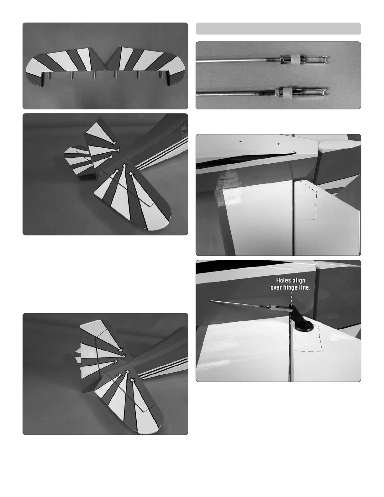
5. Locate six hinges. Apply a drop of oil to each hinge to
❏
prevent glue from getting into the hinge when installing them
in the stabilizer.
11
Page 12
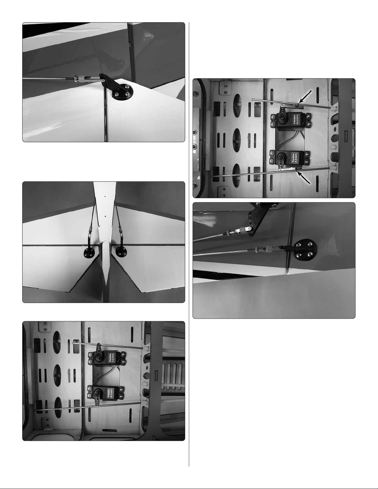
Install the Elevator and Rudder Servos
1. Install a 4-40 nut, clevis keeper and 4-40 threaded clevis
❏
onto two 4-40 x 48" [1220mm] threaded wires.
6. Mix 1/4 ounce of 30 minute epoxy. Use a toothpick to
❏
apply a small amount of glue into each of the hinge holes
in the stab and both halves of the elevator. Apply 30 minute
epoxy to one side of each of the six hinges and install them in
the holes in the left and right half of the elevator. Clean excess
epoxy with a paper towel and rubbing alcohol. Move quickly
and apply 30 minute epoxy to the other half of the hinge and
then install each elevator to the horizontal stabilizer. Allow
the glue to harden.
2. On the bottom of each elevator there is a plywood
❏
plate. Install one of the clevises into the second hole from
the bottom of a control horn. Slide the 4-40 wire into the hole
in the side of the fuselage and the place the control horn onto
the plywood plate. The holes in the control horn should be
aligned over the hinge line.
7. Use the same technique to install the rudder to the fin.
❏
3. Once the horn is properly positioned mark the location
❏
of the control horn mounting holes onto the elevator with a felt
tip marker. On each of the marks drill a 3/32" [2.4mm] hole
through the plywood plate. Do not drill through the top of
the elevator!
12
Page 13
4.
Install and then remove a #4 x 3/8" sheet metal screw
❏
into each of the holes. Apply a drop of thin CA glue into each of
the holes to harden the threads. Once the glue has hardened
secure the control horn to the elevator with the four screws.
the outer hole in each of the servo arms. Place the two servos
in the servo tray with the servo arms aligned with the pushrod
wires. Drill a 1/16" [1.6mm] hole through each of the mounting
holes in the two servos. Install and remove a servo mounting
screw into each of the holes you drilled. Apply a drop of thin
CA glue to harden the threads. When the glue has hardened,
secure the servos with the screws.
5. Use the same technique for the remaining elevator half.
❏
6. Install the grommets and eyelets onto two servos. Cut
❏
three arms from a four arm servo horn, center the servo and
install the horn onto the servo. Install a 4-40 solder clevis into
7. Center the elevator halves and the two elevator servo
❏
arms. Using the solder clevis as your guide, make a mark on
the pushrod wire where it needs to be cut. Remove the clevis
from the elevator control horn and remove the pushrod from
the fuselage. Do this for both pushrod wires.
Once the wires have been removed cut the wires on the
marks you made. Solder a 4-40 solder clevis to the wire
using the same procedure used on the ailerons. When the
solder has cooled remove the threaded clevis and 4-40 nut
from the threaded end of the wires. Slide a silicone clevis
keeper onto the solder clevis. Re-install the wire through the
front of the fuselage into the pushrod guide tubes. Attach
the clevis from each pushrod wire to the outer hole of the
servo arm. Re-install the nuts and threaded clevises onto
each wire, adjusting them so that the elevators are centered.
Then secure the elevators with the clevises.
8. Install a 4-40 nut, clevis keeper and 4-40 threaded clevis
❏
onto the remaining 4-40 x 48" [1220mm] threaded wire.
13
Page 14
9. Just like the elevator there is a plywood plate at the
❏
bottom of the rudder. Install the clevis into the second hole
from the bottom of a control horn. Slide the 4-40 wire into the
hole in the side of the fuselage and the place the control horn
onto the plywood plate. The holes in the control horn should
be aligned over the hinge line.
10. Once the horn is properly positioned mark the location
❏
of the control horn mounting holes onto the rudder with a felt
tip marker. On each of the marks drill a 3/32" [2.4mm] hole
through the plywood plate. Do not drill through the top of
the rudder!
11.
Install and then remove a #4 x 3/8" sheet metal screw
❏
into each of the holes. Apply a drop of thin CA glue into each of
the holes to harden the threads. Once the glue has hardened
secure the control horn to the elevator with the four screws.
12. Install the grommets and eyelets on to a servo. Cut
❏
three arms from a four arm servo horn, center the servo and
install the horn onto the servo. Install a 4-40 solder clevis into
the outer hole in each of the servo arms. Place the servo in
the servo tray with the servo arms aligned with the pushrod
wire. Drill a 1/16" [1.6mm] hole through each of the mounting
holes in the two servos. Install and remove a servo mounting
screw into each of the holes you drilled. Apply a drop of thin
CA glue to harden the threads. When the glue has hardened
secure the servo with the screws.
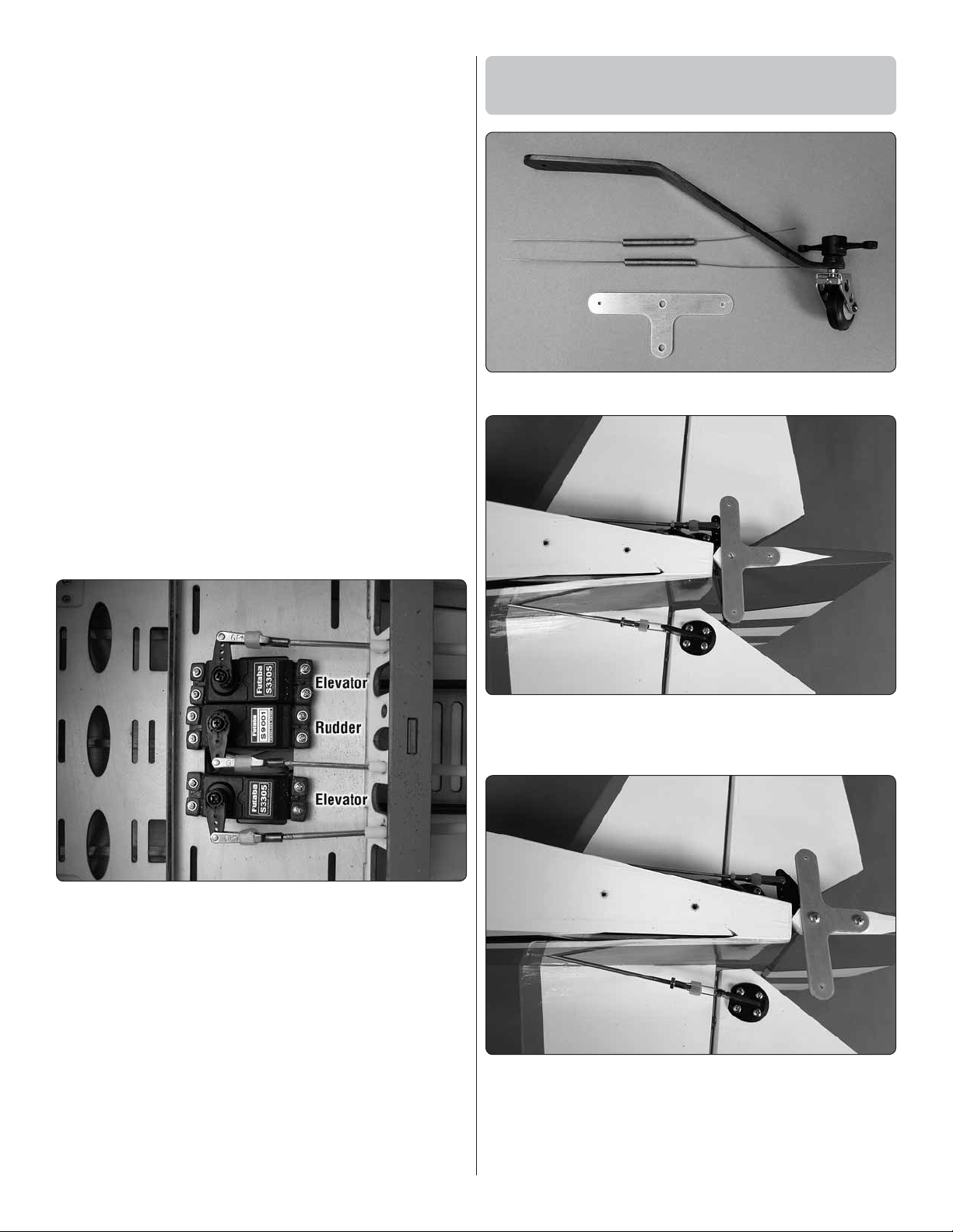
Mount the Tail Wheel, Bracket
and Support Wires
1. Locate all of the components of the tail wheel assembly.
❏
13. Center the rudder and the rudder servo arm. Using the
❏
solder clevis as your guide, make a mark on the pushrod wire
where it needs to be cut. Remove the clevis from the rudder
control horn and remove the pushrod from the fuselage. Cut
the wire on the mark you made. Solder a 4-40 solder clevis
to the wire using the same procedure used on the elevators.
When the solder has cooled remove the threaded clevis
and 4-40 nut from the threaded end of the wires. Slide a
silicone clevis keeper onto the solder clevis. Re-install the
wire through the front of the fuselage into the pushrod guide
tubes. Attach the clevis from each pushrod wire to the outer
hole of the servo arm. Re-install the nut and threaded clevis
onto the wire, adjusting it so that the rudder is centered. Then
secure the rudder with the clevis.
2. Place the aluminum “T” bracket on the bottom of the
❏
rudder. Mark the location of the mounting holes with a felt tip
marker onto the bottom of the rudder.
3. Drill a 3/32" [2.4mm] hole into the rudder on each of
❏
the marks. Insert and then remove a #4 x 3/8" [9.5mm] sheet
metal screw into each of the holes you drilled. Apply a drop
of thin CA glue into each of the holes to harden the threads.
Once the glue hardens secure the “T” bracket to the rudder
with two #4 x 3/8" [9.5mm] screws.
14
Page 15

4. On the bottom of the fuselage just ahead of the rudder
Brass Crimp
Connector
2-56 Nut
Clevis
Keeper
2-56 Threaded
Clevis
2-56 Brass
Coupler
Braided
Wire
❏
are two pre-drilled holes. Insert and then remove a #4 x 3/8"
[9.5mm] screw into each of the holes. Apply a drop of thin CA
glue into each of the holes to harden the threads. Once the
glue hardens secure the tail wheel bracket to the fuselage.
5. Center the rudder and the tail wheel. Secure the two
❏
springs to the arm on the tail wheel assembly and the “T”
bracket by twisting the wire through and around the holes in
the brackets. Keep the tension from the two springs equal on
both sides of the tail wheel bracket.
7. Locate the aluminum tail wire bracket. Position it on
❏
the bottom of the fuselage over the pre-drilled holes. Insert
and then remove a #4 x 3/8 screw into each of the two holes.
Apply a drop of thin CA glue into the holes to harden the
threads. After the glue has hardened, secure the bracket to
the fuselage with the screws.
6. Locate the small spool of braided wire, two 2-56 brass
❏
couplers, two 2-56 nuts, two silicone clevis keepers and two
copper crimp connectors. Slide a crimp connector onto one
end of the braided cable. Insert the braided cable into the hole
in the end of one of the 2-56 brass couplers and loop it back
through the crimp connector. Crimp the connector tightly with
a pliers to secure the connector to the braided cable. Install a
2-56 nut, clevis keeper and 2-56 threaded clevis.
8. Attach the clevis to one side of the bracket. Insert the
❏
other end of the wire into the hole in the stab. Continue
inserting the wire into holes in the fin and the opposite side
15
Page 16

of the stab. Assemble another clevis and brass coupler the
same as you did in step 6. Install the clevis assembly into the
bracket and then insert the wire into the brass coupler, pull
the wire tight and secure the wire with the crimp connector.
Final tensioning of the cable can be done by adjusting the
clevises.
The next few steps cover installation of an electric motor. If
you will be installing a gasoline engine skip ahead to INSTALL
THE ENGINE, THROTTLE/CHOKE SERVOS AND IGNITION
SWITCH on page 19.
ELECTRIC MOTOR INSTALLATION
3. On page 43 of the instruction manual is a paper template
❏
for the Great Planes large engine mount. Cut the pattern from
the manual. Tape the pattern to the firewall, aligning the lines
on the template with the lines on the firewall.
1. When installing an electric motor it will require venting
❏
through the fuselage. Inside of the fuselage just behind the
servo tray we have installed air vents. Cut the covering to
reveal the vents.
2. To install the motor you will need a motor mount.
❏
We recommend the Great Planes large engine mount
(GMPG1260). This mount is strong, lightweight and allows
for infinite adjustment to accommodate most motor brands.
4. Drill a 1/16" pilot hole on the crosses on the paper and
❏
through the firewall. Remove the template and then drill a
3/16 hole through each of the four pilot holes you drilled.
5. Install a 8-32 blind nut into each of the four holes you
❏
drilled, installing the blind nuts into the backside of the firewall.
6. Following the instructions with the motor mount, secure
❏
your motor to the mount. Secure the mount to the firewall with
16
Page 17

four 8-32 x 3/4" [19mm], flat washers, lock washers and a
drop of threadlocker. When positioning the motor adjust the
mount so that the distance from the front of the firewall to the
front of the drive washer is 6-5/16" [156mm].
7. Locate the plywood ESC mounting tray. Place the ESC
❏
onto the tray. Mark the location for each of the mounting tabs
onto the tray. Drill a 3/32" [2.4mm] hole on each of the marks.
8. Secure the ESC to the tray with three #4 x 3/8" [10mm]
❏
screws and #4 flat washers.
9. Just behind the landing gear is a hardwood stick that will
❏
be used for securing your ESC tray. Slide the tray to the front
of the firewall. Insert the two tabs into the slots in the firewall
to retain the front of the tray and let the back of the tray rest
on the hardwood stick. Drill a 1/16" [1.6mm] hole through the
mounting holes in the tray, into the hardwood stick. Secure
the tray to the stick with three #2 x 3/8" [10mm] screws and
#2 flat washers.
10. To connect the motor to the ESC you will need three
❏
Great Planes 6mm Male/4mm Female Bullet Adapters
(GPMM3119). Connect the leads from the motor to the ESC.
17
Page 18

11.
❏
❏
Included in the kit is a small plywood plate to cover a
portion of the hole that the motor leads pass through. Place the
plate against the firewall and mark the location of the mounting
holes. Drill a 1/16th [1.6mm] hole through the mounting holes in
the plate. Secure the plate with three #2 x 3/8" [10mm] screws
and #2 flat washers.
12. Your batteries fit nicely on the tray just behind the
firewall. Cut the included hook and loop straps to fit around
the tray and your choice of batteries. The straps can be
inserted through the slots in the tray.
13. We have included a secondary battery tray. Depending
❏
on your choice of motor and batteries your airplane could be
slightly nose heavy. If this is the case install the secondary
battery tray as shown. It can be secured by drilling a 3/32"
[2.5mm] hole through each of the mounting holes and into the
plywood rails on each side of the fuselage. Secure the tray
with five #4 x 3/8" [10mm] screws. With this tray in place you
have a wide range of positions for installing the batteries and
adjusting the balance of your model without adding weight.
If you installed the Electric Motor skip ahead to INSTALL THE
COWL on page 25.
18
Page 19

INSTALL THE ENGINE,
THROTTLE/ CHOKE SERVOS
AND IGNITION SWITCH
The following engine mounting instructions show the
installation of the DLE30 side exhaust gas engine. An
additional DLE engine, the DLE35, mounts very similar to
the DLE 30. We do make note of the modification required
for installing it in these instructions. The installation of
other brands of engines will be similar and the following
instructions can be used as a guide.
2. Install engine mounting bolts, flat washers and lock
❏
washers from the back of the firewall. (The mounting hardware
is not included in this kit. It should come with the engine. If
your engine did not include fender washers, purchase four
fender washers to mount the bolts from behind the firewall.
The fender washer helps to better spread the load from the
engine). Apply a drop of thread locker to each bolt before
installing them into the engine stand-offs. The standoffs can
be permanently mounted. The bolts mounting the engine to
the stand-offs should not be permanently installed as they will
be removed several times during the process of installing the
engine. Note: For the DLE 35RA installation you may need
to remove some of the triangle stock from the back side of
the firewall.
1. Drill a 3/16" [4.8mm] hole through the firewall at each
❏
location marked with a “+” if you are installing the DLE 30. If
you are installing an engine with a different mounting bolt
pattern the firewall has crosshairs embossed on it to help
locate the correct mounting location.
Note: If you are mounting the DLE 35 RA the “+” marks on the
top of the firewall will match with two of the mounting holes of
the engine. You will need to make measurements for the lower
mounts as they are a bit further apart. Additionally you will
need to remove a part of the triangle stock as shown. Please
use the paper template on page 43 for locating the holes for
the DLE35RA after you have removed the triangle stock. When
installing the rear exhaust muffler with the DLE 35 you will
need to remove a small amount of the bottom of the firewall.
4. For reference, the distance from the front of the firewall
❏
to the front of the drive washer is 6-5/16" [156mm].
Many modelers have their own preferences for connectors
and throttle linkage. We have provided materials for a secure
and safe throttle linkage. We have also included a method to
connect a linkage to the choke. This will require the use of
an additional servo for the choke linkage. Some modelers
may prefer a mechanical choke linkage. Review the following
procedure. Then, modify it as you wish to fit your personal
preferences.
19
Page 20

5. Install a 2-56 ball link and 2-56 nuts to both the throttle
❏
and the choke. Be sure to apply a drop of thread locker to the
threads on the ball link.
for the throttle and choke. Drill a 1/4" [6.4mm] hole on the
mark for the fuel line. (Check the diameter of your fuel line to
be sure that a 1/4" [6.4mm] hole is correct).
6. To properly align the throttle linkage with the throttle
❏
servo you will need to rotate the throttle arm 180°. Remove
the screw, rotate the arm, apply a drop of thread locker to the
screw and re-insert it.
8. Assemble the fuel tank stopper assembly with the fuel
❏
tubes as shown. The easiest way is to first solder a fuel line
barb (not included) onto one end of all three tubes. We used
the 1/8" Dubro Fuel Line Barbs (DUBQ0670). Insert the tubes
into the stopper with the metal plates, and then solder a barb
onto the other end of the two short tubes. Bend the vent
tube and connect the pickup and fueling/defueling lines (not
included) to the short tubes. Connect the clunks to the Tygon
Fuel lines (not included).
7. Make marks on the firewall where the throttle, choke
❏
and fuel line will pass through. Remove the engine from the
stand-offs. Then drill a 3/16" [4.8mm] hole through the firewall
9. Install the fuel tank stopper assembly in the fuel tank.
❏
Check that the clunks move around freely in the fuel tank.
Tighten the fuel tank stopper screw.
20
Page 21

10. Install fuel lines onto the brass tubes from the fuel tank.
❏
To route the fuel lines as shown here you will need to use a 6"
[152mm] length of tubing on the fill line, a10" [254mm] length
of tubing on the vent line and a 4" [102mm] length of tubing
on the carburetor line.
fuselage if your carburetor happens to be on the opposite
side of the engine than our DLE 30. Install the servos with
the hardware provided with your servos.
13.
Locate one of the nylon ball links. Cut it in half as shown.
❏
11. From the hook and loop material provided with the kit
❏
cut two straps to fit through the slots in the plywood tray and
around the fuel tank to secure the tank in the fuselage.
12. Install the throttle and choke (optional) servos as
❏
shown. The servos can be mounted on both sides of the
14. Locate the 11-3/4" plastic pushrod tube. Cut a 4"
❏
[102mm] piece from it. Roughen the end of the tube with 120
grit sandpaper. Use 5-minute epoxy and glue the tube into
the hole you drilled for the choke linkage. When positioning
the tube it should be flush with the firewall.
21
Page 22

15. Thread a 2-56 x 6" [152mm] threaded wire into the
❏
nylon ball link you cut.
17. Move the choke arm towards the firewall. Position the
❏
servo arm as shown. Bend the pushrod wire in line with the
outer hole in the servo arm. Drill the outer hole in the servo
arm with a 5/64" [2mm] drill.
16. Slide the wire into the tube, inserting it through the
❏
front of the firewall. Snap the nylon ball link onto the ball link
on the choke servo.
18. Locate the plywood pushrod support and the two
❏
1/4" x 1/4" x 1/2" [6 x 6 x12mm] hardwood sticks.
22
Page 23

19. Slide the support over the wire and position it over the
❏
pushrod tube in the approximate location shown. The exact
placement is not critical, just be sure it will not conflict with the
throttle arm. Be sure the length of the pushrod support is not
too long, putting any pressure on the pushrod tube. If needed
shorten the support until it supports the pushrod tube properly.
20. Once the support is
❏
the proper length, glue a 1/4"
x 1/4" x 1/2" [6 x 6 x12mm]
hardwood stick on each side of
the support and then glue the
support to the fuel tank tray and
the pushrod tube.
23. Drill the outer hole in the throttle servo arm with a 5/64"
❏
[2mm] drill.
24. Thread a nylon ball link onto a 2-56 x 6" pushrod wire.
❏
Insert the wire into the plastic tube through the firewall. Snap
the nylon ball link onto the metal ball link on the throttle. Adjust
the throttle and the servo arm position. Bend the pushrod wire
in line with the outer hole in the servo arm as you did with
the choke servo. Secure the pushrod wire with a nylon faslink.
21. Insert the pushrod wire into the outer hole of the servo
❏
arm and secure the wire to the servo arm with a nylon Faslink.
22. Cut a 2" [51mm’] length of tube from the remaining
❏
portion of the plastic pushrod tube you cut in step 15.
Roughen the end of the tube with 120 grit sandpaper. Use
5-minute epoxy and glue the tube into the hole you drilled for
the throttle linkage.
25. Install a switch and charge jack for the electronic
❏
ignition module in the right side of the fuselage.
26. Place a piece of foam (not included) between the
❏
ignition module and the plywood accessory tray. Secure the
module with the provided hook and loop material. Do the
same with the ignition module battery.
23
Page 24

27. Make all of the required connections between the
❏
battery, switch harness and the ignition module following the
instructions with the engine.
and #2 flat washers. The spark plug lead and ignition module
connection should feed through the opening in the firewall.
Screw the plywood plate in place with four #2 x 3/8" [9mm]
screws and #2 flat washers as shown in the photo.
29. The installation shown of the DLE 30 assumes the
❏
installation of the stock muffler, but if you choose to install a
Pitts Style muffler you will find that the wires from the ignition
module will contact the muffler. If you install a Pitts muffler
you need to use the plywood plate shown here to route the
wires away from the muffler.
28. Insert the accessory tray under the fuel tank and insert
❏
the two tabs in the front of the tray into the slots in the firewall
to retain the front of the tray. Let the back of the tray rest
on the hardwood stick. Drill a 1/16" [1.6mm] hole through
the mounting holes in the tray and into the hardwood stick.
Secure the tray to the stick with three #2 x 3/8" [10mm] screws
24
Page 25

30. These three photos show three engine installations
❏
and the plywood plate installed to assure the ignition leads
do not touch the muffler.
INSTALL THE COWL
1. Locate the plywood cowl ring. Secure it to the firewall
❏
with four 6-32 x 3/4" [19mm] socket head cap screws, #6 lock
washers and #6 flat washers.
2. Locate three plywood disks. These will aid you in
❏
centering and assembling the cowl. These three disks need to
be glued together and centered with one another. The easiest
way to do this is to slide disk #1 onto the front of the engine.
Then glue disk #2 to disk #1, again sliding disk #2 onto the
engine. When the glue has hardened, slide disk #3 onto the
crankshaft and glue it to disk #2. This assembly does not
require much glue for where it will be used. A small amount
of medium CA glue should work well. Once the glue has
hardened, remove it from the front of the engine.
3. Measure inside the cowl from the back of the cowl
❏
approximately 1" [25mm]. Lightly sand (roughen) that area
inside of the cowl with 120 grit sandpaper and then wipe the
area clean with a paper towel wetted with rubbing alcohol.
25
Page 26

4. Slide the cowl over the engine and then slide the ring
❏
assembly onto the engine. Be sure the ring assembly fits tight
against the face of the engine drive washer.
6. Mix approximately 1/2 ounce of 30-minute epoxy and
❏
a small amount of micro balloons to thicken the glue. Use a
long stick or rod and apply a small amount of epoxy to the
cowl ring and the cowl. Apply the glue in four to six spots to
tack glue the cowl to the cowl ring. Allow the glue to harden.
7. Remove the disk assembly from the front of the cowl.
❏
Use a long handled ball wrench and remove the bolts holding
the cowl in place. Remove the cowl, being careful not to break
the cowl ring from the cowl where you glued them together.
5. Slide the cowl forward, fitting it tight to disk #2. Be
❏
sure the black trim on the cowl and fuselage align. Slide
the windshield onto the fuselage. This will assure you have
adequate clearance once the cowl is glued in place.
8. Glue the cowl to the cowl ring by applying a fillet of Shoe
❏
Goo® or good quality silicone glue to the front of the cowl ring.
A Popsicle stick works well for spreading the glue. Set the
cowl aside and allow the glue to cure.
26
Page 27

9. We have shown the installation of the DLE stock
❏
muffler. Doing so will require you to cut more of the cowl
away than you may like. A Pitts style muffler will be a more
compact installation and require less of the cowl away. If you
will be installing a Pitts style muffler you will need make a
modification to the firewall shown in the next step.
10. Locate the plywood plate shown here. Screw it in place
❏
as shown. This will allow the spark plug lead and the ignition
lead to be routed clear of the muffler.
11. Install the muffler of your choice.
❏
12. Slide the cowl onto the front of the fuselage. Work
❏
slowly and mark where the cowl needs to be cut to allow it to
fit completely over the engine. Continue until the cowl will slip
over the engine and can be bolted to the firewall.
13. Once you have successfully mounted the cowl, make
❏
any additional modifications to the cut outs in the cowl.
14. Make two holes in the cowl for the fuel fill line and the
❏
vent line.
27
Page 28

INSTALL THE WHEELS, WHEEL
PANTS AND WING STRUTS
3.
Insert a 6-32 set screw into two of the 3/16" [4.8mm]
❏
wheel collars. Slide one wheel collar onto the axle followed by
the wheel and then another 3/16" [4.8mm] wheel collar. Center
the wheel and then tighten the set screws. Be sure the wheel
collar on the end of the axle rests on the flat spot you made.
1. Cut the two wheel axles to a length of 1-13/16" [46mm].
❏
Install the axle to the main landing gear securing it with the
two 5/16-24 nylon lock nuts.
2. Make a flat spot on the end of the axle. The flat spot
❏
should be towards what will be the bottom of the airplane.
4. Slide the wheel pant over the wheel and axle. Secure the
❏
pant to the landing gear with two 4-40 x 1/2" [13mm] socket
head cap screws, #4 lock washer and #4 flat washer. Apply
a drop of thread locker before inserting the screws into the
28
Page 29

wheel pant. Adjust the wheel collars to be sure the wheel is
centered in the pant and does not bind against it. Repeat this
for the remaining wheel pant.
5. Install the wing to the fuselage, securing it with two
❏
1/4-20 x 2" [51mm] nylon wing bolts.
7. Your kit includes 2 pair of struts. Each pair is comprised
❏
of a 24" [610mm] and 25-1/2" [647mm] long strut. The 24"
[610mm] strut is the front strut and the 25-1/2" [647mm strut]
is the rear strut.
6. Locate the two wing strut brackets. Slide the end of
❏
the bracket with two holes into the slot on each side of the
fuselage. Secure the bracket to the fuselage with two #4 x
1/2" [13mm] socket head cap screws, #4 lock washers and
#4 flat washers. Be sure to apply a drop of thread locker on
each of the screws before inserting them into the brackets.
8. There are two different brackets used for mounting the
❏
strut. You will need two of the 90 degree brackets and two of
the angle brackets for each wing half.
9. Look closely at the end of each strut. You will see that
❏
on one end of each strut there is a slot rather than a hole. The
slotted end of the strut is the end that will be attached to the
bracket on the fuselage.
29
Page 30

10.
Install an angled bracket to the end of each strut with a
❏
4-40 x 1/4" [6mm] socket head cap screw, 4-40 lock washer and
4-40 nut. Be sure to put a drop of thread locker on each screw.
11.
Look closely at the bottom of the wing. You will find four
❏
mounting holes for the struts. Each of the mounting holes has a
4-40 blind nut pre-installed in the wing. The two mounting holes
closest to the wing tip are for the long wing struts. The two
holes near the center of the wing are for the interplane struts.
#4 lock washer, mounting it to the bracket extending from the
fuselage and the two blind nuts located in the wing near the wing
tip. Attach the struts to the fuselage with a 4-40 x 1/2" [13mm]
socket head cap screw, #4 flat washer and #4 lock washer.
14. Locate the two interplane struts. You will notice
❏
the threaded wires are a bit loose inside the tube. This is
intentional so you can make the final adjustments required
for the installation of the strut.
12. Install a 90 degree bracket into each of the two holes
❏
near the center of the wing for the interplane struts. Each
bracket should be secured with a 4-40 x 1/2" socket head
cap screw, #4 lock washer and #4 flat washer. The bracket
should be position as shown
13.
Install the wing struts to the wing and the fuselage with a
❏
4-40 x 1/2" [13mm] socket head cap screw, #4 flat washer and
15. Insert the threaded portion of the wire through the
❏
strut. You may need to rotate the threaded wire slightly so it
protrudes through the strut as shown in the photo. Once you
have the wires adjusted work some epoxy or medium CA into
the tube to help secure the wire inside the tube.
16. Secure the interplane strut to the wing strut with a 2-56
❏
nut, #2 flat washer and #2 lock washer.
30
Page 31

17. Secure the opposite end of the interplane strut to the
❏
bracket you installed in the wing with a 4-40 x 1/2" [13mm]
socket head cap screw, #4 flat washer and #4 lock washer.
20. Once you have completed the strut assembly remove
❏
the wing. Because the wing is in two pieces you can remove
the bolt on the struts that attaches to the fuselage. Remove
the wing bolts and then slide the wing out of the wing saddle
continuing back towards the tail. Once the wing is far enough
aft of the wing saddle the struts will be wider than the fuselage.
At that point you can lift the wing off the fuselage. Using this
method for installing and removing the wing you can leave
the struts on the wing halves. This makes installation of the
wings and struts quick and easy.
COMPLETE THE RADIO
INSTALLATION
18. After installing the nuts and washers you may wish to
❏
use a high speed motor tool and cut-off wheel to cut off the
excess threaded wire.
19. Repeat steps 9 – 16 for the opposite wing strut.
❏
1. Both sides of the fuselage have pre-cuts in the fuselage
❏
for the radio switch and charge jack. Determine which of the
openings best fit your switch and then cut the covering away
from the fuselage. Install your radio switch and the charge
jack if you intend to use one.
31
Page 32

2. Install your receiver battery of choice to either side of the
❏
fuselage. Place a piece of R/C foam rubber under the battery
and secure the battery with Velcro®. Plug your servos into
the receiver, place R/C foam under the receiver and secure
it with Velcro®.
3. Install a 20" [500mm] servo lead into the aileron and the
❏
flap port of your receiver.
4. Install a dual servo lead or “Y” harness on the flap leads
❏
and the aileron leads in your wing.
INSTALL THE COCKPIT,
PILOT AND SPINNER
1. Locate the cockpit floor and the seat backs. Glue the
❏
seat backs to the cockpit floor.
2. Remove the windshield and un-do the Velcro® holding
❏
the fuel tank in place. Test fit the cockpit floor inside the
fuselage. The cockpit floor is pre-cut and should fit without any
modifications. The easiest way to install the floor is through
the front of the cockpit. When it is properly positioned on the
frame the fuel tank will overhang slightly on the floor.
32
Page 33

3. For our installation we applied heat shrink tubing to
❏
the aileron and flap servo leads and applied glue to the heat
shrink, gluing them to the sides of the cockpit frame. This
required an opening to be cut in the cockpit floor. Make any
modifications to your floor that are required to accommodate
the servo leads.
4. We have included a black plastic cover to disguise the
❏
fuel tank.
6. Attach a 1" [25mm] piece of self-adhesive Velcro® to the
❏
back of the fuel tank. This will secure the cover and allow it to
be easily removed if you need to service the fuel tank.
5. Attach a 1" [25mm] piece of self-adhesive Velcro® to the
❏
inside of the cover.
7. Now is a good time to decide if you will install a pilot. We
❏
used the Great Planes 1/4-scale sport pilot figure (GPMQ9010).
Because the cockpit floor is vacuum formed plastic it is lightweight but does not provide a strong base for mounting a pilot
so you will need to make a plywood base for you particular pilot.
Additionally, most pilot busts will be too short and will need
33
Page 34

to be built up to make the pilot sit tall enough in the cockpit.
We used the Great Planes sport pilot and added a block of
balsa to the base and sanded it to match the shape of the
pilot. Then we painted it to match the pilot. Because most of
the pilot base is below the window lines the overall effect is
good and the added balsa base does not take away the look
of the finished pilot. Once you have the pilot at the proper
height you will need to make a mounting plate. We used a
piece of light plywood (not included) and made it wide enough
to reach the rails on both sides of the fuselage. To make the
base less obvious we painted it flat black to match the floor.
9. Apply the instrument panel decal to the instrument panel
❏
shroud.
7. The pilot was then screwed through the cockpit floor
❏
and into the rails on the inside of the fuselage. This secures
the pilot as well as securing the front half of the cockpit floor
to the fuselage.
8. If you choose not to install a pilot, secure the floor to the
❏
rails in the fuselage by drilling four 1/16" [1.6mm] holes through
the floor and the mounting rails. Secure the floor with four
#2 x 3/8" [10mm] screws and #2 flat washers. Refer to the
above photo to see the location of the screws we installed.
10. Install the instrument panel shroud into the front of
❏
the windshield. You will notice the bottom of the shroud is cut
to allow clearance for the fuel tank. You will also notice that
there is room for the shroud to move inside the windshield.
This wiggle room will allow you to position the shroud exactly
where it needs to be. If you are doing the electric installation
you should install your batteries before gluing the shroud in
place to be sure you leave clearance room. Apply 5-minute
epoxy inside of the windshield where the shroud will make
contact. Install the windshield to the fuselage and then
position the shroud over your fuel tank or batteries. Allow the
glue to harden.
34
Page 35

two of the cowl mounting screws. Depending on which muffler
you used, you may be able to reach the screws through the
cut outs you made for the muffler. You can also cut the lower
corner of the screen as shown in the photo. This will allow you
the access you need. Once you have modified the screen or
cowl as needed, glue the screen inside the cowl.
12. Install the spinner onto the front of the engine or motor.
❏
The spinner back plate is pre-drilled for the O.S. GT33. The
spinner also comes with a bushing that will allow the back
plate to be used on smaller shafts that may be on electric
motors or glow engines. If you are using a DLE 30 the hole
in the spinner will need to be enlarged by drilling the spinner
with a 25/64" [10mm] drill bit.
11. Included in the kit is a screen that can be glued in the
❏
front of the cowl to add a nice scale detail. This installation is
optional. If you install the screen you will not have access to
35
Page 36

APPLY THE DECALS
FULL
THROTTLE
RUDDER
MOVES
RIGHT
ELEVATOR
MOVES DOWN
RIGHT AILERON
MOVES UP
LEFT AILERON
MOVES DOWN
4-CHANNEL RADIO SET UP (STANDARD MODE 2)
GET THE MODEL READY TO FLY
Refer to these pictures and the pictures on the box to
determine the location for the decals. Use the following
instructions to apply the decals.
Check the Control Directions
Check the Control Directions
1. Turn on the transmitter and receiver and center the trims.
If necessary, remove the servo arms from the servos and
reposition them so they are centered. Reinstall the screws
that hold on the servo arms.
2.
With the transmitter and receiver still on, check all the control
surfaces to see if they are centered. If necessary, adjust the
clevises on the pushrods to center the control surfaces.
1. Use scissors or a sharp hobby knife to cut the decals from
the sheet.
2. Be certain the model is clean and free from oily fingerprints
and dust. Prepare a dishpan or small bucket with a mixture
of liquid dish soap and warm water—about one teaspoon of
soap per gallon of water. Submerse the decal in the soap and
water and peel off the paper backing. Note: Even though the
decals have a “sticky-back” and are not the water transfer
type, submersing them in soap & water allows accurate
positioning and reduces air bubbles underneath.
3. Position decal on the model where desired. Holding the
decal down, use a paper towel to wipe most of the water away.
4. Use a piece of soft balsa or something similar to squeegee
remaining water from under the decal. Apply the rest of the
decals the same way.
3. Make certain that the control surfaces and the carburetor
respond in the correct direction as shown in the diagram.
If any of the controls respond in the wrong direction, use
the servo reversing in the transmitter to reverse the servos
connected to those controls. Be certain the control surfaces
have remained centered. Adjust if necessary.
Set the Control Throws
To ensure a successful fi rst fl ight, set up your Citabria
according to the control throws specifi ed in this manual.
The throws have been determined through actual fl ight
testing and accurate record-keeping, allowing the model
to perform in the manner in which it was intended. If, after
you have become accustomed to the way the Citabria fl ies,
you would like to change the throws to suit your taste, that
is fi ne. However, too much control throw could make the
model too responsive and diffi cult to control, so remember,
“more is not always better.”
1. Use a box or something similar to prop up the bottom of
❏
the fuselage so the horizontal stabilizer and wing will be level.
36
Page 37

Measure the high rate elevator throw first…
DownUp Up Down
These are the recommended control surface throws:
3/4"
[19mm]
11°
7/8"
[22mm]
11°
3/4"
[19mm]
11°
7/8"
[22mm]
11°
3/4"
[19mm]
13°
3/4"
[19mm]
13°
1-3/16"
[30mm]
17°
3/4"
[19mm]
37°
1-3/16"
[30mm]
17°
1-5/8"
[41mm]
23°
1-1/8"
[28mm]
20°
1-1/8"
[28mm]
20°
ELEVATOR
AILERON
LOW HIGH
RUDDER
DownUp Up Down
LeftRight LeftRight
5/8"
[16mm]
11°
1"
[25mm]
18°
1-5/8"
[41mm]
23°
FLAPS
Down Down
2. Hold a ruler vertically on your workbench against the
❏
widest part (front to back) of the trailing edge of the elevator.
Note the measurement on the ruler.
NOTE: The throws are measured at the widest part of the
elevators, rudder and ailerons.
3.
Move the elevator up with your transmitter and move the
❏
ruler forward so it will remain contacting the trailing edge. The
distance the elevator moves up from center is the “up” elevator
throw. Measure the down elevator throw the same way.
4. If necessary, adjust the location of the pushrod on the
❏
servo arm or on the elevator horn, or program the ATVs in
your transmitter to increase or decrease the throw according
to the measurements in the control throws chart.
5. Measure and set the low rate elevator throws and the
❏
high and low rate throws for the rest of the control surfaces
the same way.
Balance the Model (C.G.)
More than any other factor, the C.G. (center of gravity/
balance point) can have the greatest effect on how a model
fl ies and could determine whether or not your fi rst fl ight will
be successful. If you value your model and wish to enjoy it
for many fl ights, DO NOT OVERLOOK THIS IMPORTANT
PROCEDURE. A model that is not properly balanced may
be unstable and possibly unfl yable.
At this stage the model should be in ready-to-fly condition with
all of the components in place including the complete radio
system, engine, muffler, propeller, spinner and pilot. The fuel
tank should be empty.
1. If using a Great Planes C.G. Machine, set the rulers to
❏
3.5" [89mm]. If not using a C.G. Machine, use a fine-point felt
tip pen to mark lines on the top of wing on both sides of the
fuselage 3.5" [89mm] back from the leading edge measured
at the fuselage. Apply narrow (1/16" [2mm]) strips of tape
over the lines so you will be able to feel them when lifting the
model with your fingers.
This is where your model should balance for the fi rst
fl ights. Later, you may experiment by shifting the C.G. 3/16"
[4.8mm] forward or 3/16" [4.8mm] back to change the fl ying
characteristics. Moving the C.G. forward will improve the
smoothness and stability, but the model will then be less
aerobatic (which may be fi ne for less-experienced pilots).
Moving the C.G. aft makes the model more maneuverable
and aerobatic for experienced pilots. In any case, start at
the recommended balance point and do not at any time
balance the model outside the specifi ed range.
37
Page 38

2. With the wing attached to the fuselage, all parts of the
❏
model installed (ready to fly) and an empty fuel tank, place
the model on a Great Planes CG Machine, or lift it at the
balance point you marked.
3. If the tail drops, the model is “tail heavy.” If the nose
❏
drops, the model is “nose heavy.” Use Great Planes “stick-on”
lead (GPMQ4485) to balance the model. To find out how
much weight is required, place incrementally increasing
amounts of weight on the bottom of the fuselage over the
location where it would be mounted inside until the model
balances. A good place to add stick-on nose weight is to the
firewall. Do not attach weight to the cowl—this will cause
the mounting screws to open up the holes in the cowl. Once
you have determined the amount of weight required, it can
be permanently attached. If required, tail weight may be
added by cutting open the bottom of the fuse and gluing it
permanently inside.
Note: If mounting weight where it may be exposed to fuel
or exhaust, do not rely upon the adhesive on the back to
permanently hold it in place. Over time, fuel and exhaust
residue may soften the adhesive and cause the weight to
fall off. Instead, permanently attach the weight with glue or
screws.
4. IMPORTANT: If you found it necessary to add any
❏
weight, recheck the C.G. after the weight has been installed.
Balance the Model Laterally
1. With the wing level, have an assistant help you lift the
❏
model by the engine propeller shaft and the bottom of the
fuse under the TE of the fin. Do this several times.
2. If one wing always drops when you lift the model, it
❏
means that side is heavy. Balance the airplane by adding
weight to the other wing tip. An airplane that has been
laterally balanced will track better in loops and other
maneuvers.
PREFLIGHT
Identify Your Model
No matter if you fly at an AMA sanctioned R/C club site or if
you fly somewhere on your own, you should always have your
name, address, telephone number and AMA number on or
inside your model. It is required at all AMA R/C club flying sites
and AMA sanctioned flying events. Fill out the identification tag
on page 42 and place it on or inside your model.
Charge the Batteries
Follow the battery charging instructions that came with your
radio control system to charge the batteries. You should
always charge your transmitter and receiver batteries the night
before you go flying, and at other times as recommended by
the radio manufacturer.
CAUTION: Unless the instructions that came with your
radio system state differently, the initial charge on new
transmitter and receiver batteries should be done for 15
hours using the slow-charger that came with the radio
system. This will “condition” the batteries so that the next
charge may be done using the fast-charger of your choice.
If the initial charge is done with a fast-charger the batteries
may not reach their full capacity and you may be fl ying with
batteries that are only partially charged.
Balance Propellers
Carefully balance your propeller and spare propellers before
you fly. An unbalanced prop can be the single most significant
cause of vibration that can damage your model. Not only
will engine mounting screws and bolts loosen, possibly with
disastrous effect, but vibration may also damage your radio
receiver and battery. Vibration can also cause your fuel to
foam, which will, in turn, cause your engine to run hot or quit.
We use a Great Planes Precision Magnetic Prop Balancer™
(TOPQ5700) in the workshop and keep a Great Planes
Fingertip Prop Balancer (GPMQ5000) in our flight box.
Ground Check and Range Check
Run the engine for a few minutes to make sure it idles reliably,
transitions smoothly and maintains full power indefinitely.
Afterward, shut the engine off and inspect the model closely,
making sure all fasteners, pushrods and connections have
remained tight and the hinges are secure. Always ground
check the operational range of your radio before the first flight
of the day following the manufacturer’s instructions that came
with your radio. This should be done once with the engine off
and once with the engine running at various speeds. If the
control surfaces do not respond correctly, do not fly! Find and
correct the problem first. Look for loose servo connections or
broken wires, corroded wires on old servo connectors, poor
solder joints in your battery pack or a defective cell, or a
damaged receiver crystal from a previous crash.
38
Page 39

ENGINE SAFETY PRECAUTIONS
Radio Control
Failure to follow these safety precautions may
result in severe injury to yourself and others.
● Keep all engine fuel in a safe place, away from high heat,
sparks or flames, as fuel is very flammable. Do not smoke
near the engine or fuel; and remember that engine exhaust
gives off a great deal of deadly carbon monoxide. Therefore
do not run the engine in a closed room or garage.
● Get help from an experienced pilot when learning to
operate engines.
● Use safety glasses when starting or running engines.
● Do not run the engine in an area of loose gravel or sand;
the propeller may throw such material in your face or eyes.
● Keep your face and body as well as all spectators away
from the plane of rotation of the propeller as you start and
run the engine.
● Keep these items away from the prop: loose clothing, shirt
sleeves, ties, scarfs, long hair or loose objects such as
pencils or screwdrivers that may fall out of shirt or jacket
pockets into the prop.
●
Make all engine adjustments from behind the rotating propeller.
● The engine gets hot! Do not touch it during or right after
operation. Make sure fuel lines are in good condition so
fuel will not leak onto a hot engine, causing a fire.
● To stop a gasoline powered engine an on/off switch should
be connected to the engine coil. Do not throw anything into
the propeller of a running engine.
AMA SAFETY CODE (EXCERPTS)
Read and abide by the following excerpts from the Academy
of Model Aeronautics Safety Code. For the complete Safety
Code refer to Model Aviation magazine, the AMA web site or
the Code that came with your AMA license.
1) I will have completed a successful radio equipment ground
check before the first flight of a new or repaired model.
2) I will not fly my model aircraft in the presence of spectators
until I become a qualified flier, unless assisted by an
experienced helper.
3) At all flying sites a straight or curved line(s) must be
established in front of which all flying takes place with the
other side for spectators. Only personnel involved with flying
the aircraft are allowed at or in the front of the flight line.
Intentional flying behind the flight line is prohibited.
4) I will operate my model using only radio control frequencies
currently allowed by the Federal Communications Commission.
5) I will not knowingly operate my model within three
miles of any pre-existing flying site except in accordance
with the frequency sharing agreement listed [in the
complete AMA Safety Code].
9) Under no circumstances may a pilot or other person
touch a powered model in flight; nor should any part of the
model other than the landing gear, intentionally touch
the ground, except while landing.
CHECK LIST
During the last few moments of preparation your mind may
be elsewhere anticipating the excitement of the fi rst fl ight.
Because of this, you may be more likely to overlook certain
checks and procedures that should be performed before the
model is fl own. To help avoid this, a check list is provided
to make sure these important areas are not overlooked.
Many are covered in the instruction manual, so where
appropriate, refer to the manual for complete instructions.
Be sure to check the items off as they are completed.
General
1) I will not fly my model aircraft in sanctioned events, air shows,
or model flying demonstrations until it has been proven to be
airworthy by having been previously, successfully flight tested.
2) I will not fly my model aircraft higher than approximately
400 feet within 3 miles of an airport without notifying the
airport operator. I will give right-of-way and avoid flying in the
proximity of full-scale aircraft. Where necessary, an observer
shall be utilized to supervise flying to avoid having models fly
in the proximity of full-scale aircraft.
3) Where established, I will abide by the safety rules for the
flying site I use, and I will not willfully and deliberately fly my
models in a careless, reckless and/or dangerous manner.
5) I will not fly my model unless it is identified with my name
and address or AMA number, on or in the model. Note: This
does not apply to models while being flown indoors.
7) I will not operate models with pyrotechnics (any device that
explodes, burns, or propels a projectile of any kind).
1. Fuelproof all areas exposed to fuel or exhaust residue
❏
such as the cowl ring, cowl mounting blocks, wing saddle
area, etc.
2. Check the C.G. according to the measurements provided
❏
in the manual.
3. Be certain the battery and receiver are securely mounted
❏
in the fuse. Simply stuffing them into place with foam rubber
is not sufficient.
4. Extend your receiver antenna and make sure it has a
❏
strain relief inside the fuselage to keep tension off the solder
joint inside the receiver.
5. Balance your model laterally as explained in the
❏
instructions.
6. Use threadlocking compound to secure critical fasteners
❏
such as the set screws that hold the wheel axles to the struts,
screws that hold the carburetor arm (if applicable), screw-lock
pushrod connectors, etc.
7. Add a drop of oil to the axles so the wheels will turn
❏
freely.
39
Page 40

8. Make sure all hinges are securely glued in place.
❏
9. Reinforce holes for wood screws with thin CA where
❏
appropriate (servo mounting screws, cowl mounting screws,
etc.).
10. Confirm that all controls operate in the correct direction
❏
and the throws are set up according to the manual.
11. Make sure there are silicone retainers on all the
❏
clevises and that all servo arms are secured to the servos
with the screws included with your radio.
12. Secure connections between servo wires and
❏
Y-connectors or servo extensions, and the connection between
your battery pack and the on/off switch with vinyl tape, heat
shrink tubing or special clips suitable for that purpose.
13. Make sure any servo extension cords you may
❏
have used do not interfere with other systems (servo arms,
pushrods, etc.).
14. Secure the pressure tap (if used) to the muffler with
❏
high temp RTV silicone, thread locking compound or J.B.
Weld.
15. Make sure the fuel lines are connected and are not
❏
kinked.
16. Balance your propeller (and spare propellers).
❏
17. Tighten the propeller nut and spinner.
❏
18. Place your name, address, AMA number and telephone
❏
number on or inside your model.
19. Cycle your receiver battery pack (if necessary) and
❏
make sure it is fully charged.
20. If you wish to photograph your model, do so before
❏
your first flight.
21. Range check your radio when you get to the flying field.
❏
FLYING
IMPORTANT! The Citabria does not possess the selfrecovery characteristics of a primary R/C trainer and should
be fl own only by experienced R/C pilots.
Fuel Mixture Adjustments
A fully cowled engine may run at a higher temperature than
an un-cowled engine. For this reason, the fuel mixture should
be richened so the engine runs at about 200 rpm below
peak speed. By running the engine slightly rich, you will help
prevent dead-stick landings caused by overheating.
CAUTION (THIS APPLIES TO ALL R/C AIRPLANES): If,
while flying, you notice an alarming or unusual sound such
as a low-pitched “buzz,” this may indicate control surface
flutter. Flutter occurs when a control surface (such as an
aileron or elevator) or a flying surface (such as a wing or
stab) rapidly vibrates up and down (thus causing the noise).
In extreme cases, if not detected immediately, flutter can
actually cause the control surface to detach or the flying
surface to fail, thus causing loss of control followed by
an impending crash. The best thing to do when flutter is
detected is to slow the model immediately by reducing
power, then land as soon as safely possible. Identify which
surface fluttered (so the problem may be resolved) by
checking all the servo grommets for deterioration or signs of
vibration. Make certain all pushrod linkages are secure and
free of play. If it fluttered once, under similar circumstances
it will probably flutter again unless the problem is fixed.
Some things which can cause flutter are; Excessive hinge
gap; Not mounting control horns solidly; Poor fit of clevis
pin in horn; Side-play of wire pushrods caused by large
bends; Excessive free play in servo gears; Insecure servo
mounting; and one of the most prevalent causes of flutter;
Flying an over-powered model at excessive speeds.
NOTE ABOUT FLYING CHARACTERISTICS: The
rudder is VERY effective! Be gentle on the rudder until
you become familiar with its characteristics. This is of
particular importance when taking off an landing.
Takeoff
Before you get ready to takeoff, see how the model handles
on the ground by doing a few practice runs at low speeds
on the runway. Hold “up” elevator to keep the tail wheel on
the ground. If necessary, adjust the tail wheel so the model
will roll straight down the runway. If you need to calm your
nerves before the maiden flight, shut the engine down and
bring the model back into the pits. Top off the fuel, then check
all fasteners and control linkages for peace of mind.
The Citabria has a wide landing gear stance making ground
handling very good and relatively easy for maintaining straight
take-offs. Taking off directly into the wind makes ground
40
Page 41

handling relatively easy. We would recommend that whenever
possible you take off and land into the wind. Taking off in a
cross wind or landing cross wind you will need to be quick
on the rudder and may need to use ailerons to help keep the
wing level during the take off or landing roll out.
When you’re ready, point the model straight down the runway,
hold a bit of up elevator to keep the tail on the ground to
maintain tail wheel steering, then gradually advance the throttle.
As the model gains speed decrease up elevator allowing the
tail to come off the ground. One of the most important things
to remember with a tail dragger is to always be ready to apply
right rudder to counteract engine torque. Gain as much speed
as your runway and flying site will practically allow before
gently applying up elevator, lifting the model into the air. At
this moment it is likely that you will need to apply more right
rudder to counteract engine torque. Be smooth on the elevator
stick, allowing the model to establish a gentle climb to a safe
altitude before turning into the traffic pattern.
Landing
To initiate a landing approach, lower the throttle while on the
downwind leg. Allow the nose of the model to pitch downward
to gradually bleed off altitude. Continue to lose altitude, but
maintain airspeed by keeping the nose down as you turn onto
the crosswind leg. In the crosswind leg deploy the flaps. Make
your final turn toward the runway (into the wind) keeping the
nose down to maintain airspeed and control. Level the attitude
when the model reaches the runway threshold, modulating
the throttle as necessary to maintain your glide path and
airspeed. If you are going to overshoot, smoothly advance
the throttle (always ready on the right rudder to counteract
torque) and climb out to make another attempt. When you’re
ready to make your landing flare and the model is a foot or
so off the deck, smoothly increase up elevator until it gently
touches down. Once the model is on the runway and has lost
flying speed, hold up elevator to place the tail on the ground,
regaining tail wheel control.
Flight
For reassurance and to keep an eye on other traffic, it is a
good idea to have an assistant on the flight line with you. Tell
him to remind you to throttle back once the plane gets to a
comfortable altitude. While full throttle is usually desirable for
takeoff, most models fly more smoothly at reduced speeds.
Take it easy with the Citabria for the first few flights, gradually
getting acquainted with it as you gain confidence. Adjust the
trims to maintain straight and level flight. After flying around
for a while, and while still at a safe altitude with plenty of fuel,
practice slow flight and execute practice landing approaches
by reducing the throttle to see how the model handles at
slower speeds. Add power to see how she climbs as well.
Continue to fly around, executing various maneuvers and
making mental notes (or having your assistant write them
down) of what trim or C.G. changes may be required to fine
tune the model so it flies the way you like. Mind your fuel level,
but use this first flight to become familiar with your model
before landing.
The Citabria is a very solid flying airplane. It will perform all
of the typical aerobatic maneuvers you would expect. Loops,
rolls and hammerheads are performed as you would expect.
Start slowly with maneuvers requiring use of the rudder as the
rudder is very effective. With the flaps deployed the airplane
flies very slowly, yet remains stable. When you deploy the
flaps expect it to balloon a bit. It is not severe but watch
for it. We found that if you mix in 2° of down elevator when
the flaps are fully deployed, the ballooning is eliminated.
We recommend you spend some time flying with the flaps
deployed, flying at slower speeds.
If you are not accustomed to an airplane with flaps you will
discover that landings are slightly different. A typical model
without flaps will generally initiate a landing approach with
a gradual reduction in altitude so that on the final approach
you will be at a fairly low altitude and will drive the airplane
to the runway. The Citabria lands best if you make your final
approach at about 100 feet (30 meters) as you approach the
end of the runway. Gradually reduce your speed, point the
nose towards the end of the runway maintaining a steady
descent. Level the airplane about three feet (1 meter) above
the runway and allow the plane to touch down on the main
gear and roll out until the tail naturally settles onto the runway.
One final note about flying your model. Have a goal or flight
plan in mind for every flight. This can be learning a new
maneuver(s), improving a maneuver(s) you already know,
or learning how the model behaves in certain conditions
(such as on high or low rates). This is not necessarily to
improve your skills (though it is never a bad idea!), but more
importantly so you do not surprise yourself by impulsively
attempting a maneuver and suddenly finding that you’ve run
out of time, altitude or airspeed. Every maneuver should be
deliberate, not impulsive. For example, if you’re going to do a
loop, check your altitude, mind the wind direction (anticipating
rudder corrections that will be required to maintain heading),
remember to throttle back at the top, and make certain you
are on the desired rates (high/low rates). A flight plan greatly
reduces the chances of crashing your model just because
of poor planning and impulsive moves. Remember to think.
Have a ball!
But always stay in control and fly in a safe manner.
GOOD LUCK AND GREAT FLYING!
41
Page 42

This model belongs to:
Name
Address
City, State, Zip
Phone Number
AMA Number
42
Page 43

DLE 35RA MOUNTING PATTERN
T
This pattern is oriented for an inverted engine installation. Examine the mounting holes on
the engine and be sure you orient the drilling pattern for the orientation of your engine.
70mm
54mm
80mm
GREAT PLANES BRUSHLESS LARGE MOTOR MOUN
RIMFIRE 1.60
47mm
47mm
43
Page 44

 Loading...