

Page 1
INSTRUCTION MANUAL
SPECIFICATIONS
Wingspan:
Wing Area: 1545 in
WARRANTY
Great Planes® Model Manufacturing Co. guarantees this kit to
be free from defects in both material and workmanship at the
date of purchase. This warranty does not cover any component
parts damaged by use or modification. In no case shall Great
Planes’ liability exceed the original cost of the purchased kit.
Further, Great Planes reserves the right to change or modify this
warranty without notice.
In that Great Planes has no control over the final assembly or
material used for final assembly, no liability shall be assumed nor
accepted for any damage resulting from the use by the user of
the final user-assembled product. By the act of using the
user-assembled product, the user accepts all resulting liability.
If the buyer is not prepared to accept the liability associated
with the use of this product, the buyer is advised to return
68.5 in
[1740mm]
2
[99.7 dm2]
Weight:
Wing
Loading:
19– 20 lb
[8620 – 9070 g]
28– 30 oz /ft
[85–92 g/dm2]
Length: 80.5 in
[2045mm]
2
Radio: 7-Channel minimum
Engine: 3.0 cu in [50cc]
this kit immediately in new and unused condition to the
place of purchase.
To make a warranty claim send the defective part or item to
Hobby Services at the address below:
Hobby Services
3002 N. Apollo Dr. Suite 1
Champaign IL 61822 USA
Include a letter stating your name, return shipping address, as
much contact information as possible (daytime telephone
number, fax number, e-mail address), a detailed description of
the problem and a photocopy of the purchase receipt. Upon
receipt of the package the problem will be evaluated as quickly
as possible.
READ THROUGH THIS MANUAL BEFORE STARTING CONSTRUCTION. IT CONTAINS IMPORTANT
INSTRUCTIONS AND WARNINGS CONCERNING THE ASSEMBLY AND USE OF THIS MODEL.
Champaign, Illinois
(217) 398-8970, Ext 5
airsupport@greatplanes.com
Entire Contents © Copyright 2009 GPMA1421 Mnl
Page 2
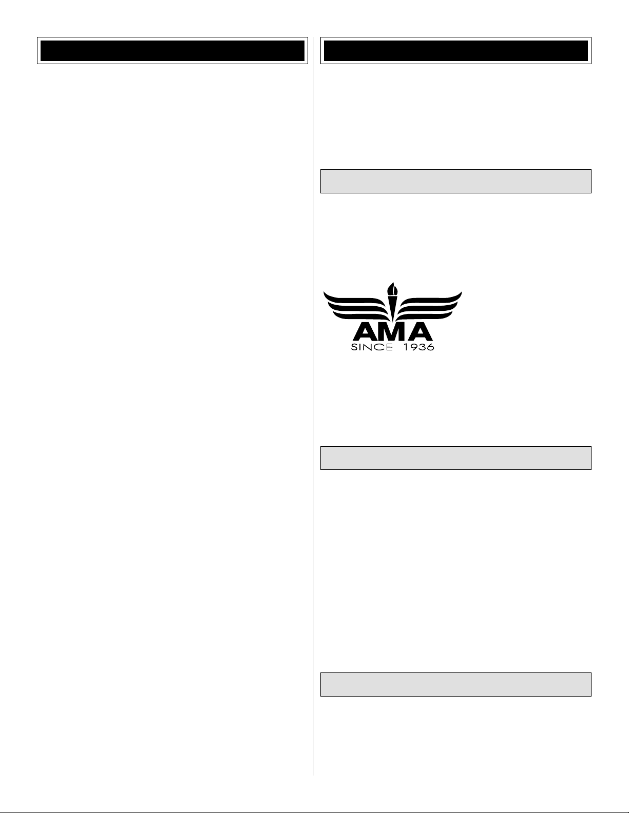
TABLE OF CONTENTS
INTRODUCTION
INTRODUCTION . . . . . . . . . . . . . . . . . . . . . . . . . . . . . . . .2
SAFETY PRECAUTIONS . . . . . . . . . . . . . . . . . . . . . . . . . 3
DECISIONS YOU MUST MAKE. . . . . . . . . . . . . . . . . . . . . 3
Radio Equipment . . . . . . . . . . . . . . . . . . . . . . . . . . . . .3
Engine Recommendations. . . . . . . . . . . . . . . . . . . . . .4
Engine Spinner . . . . . . . . . . . . . . . . . . . . . . . . . . . . . .4
ADDITIONAL ITEMS REQUIRED . . . . . . . . . . . . . . . . . . .4
Required Hardware and Accessories . . . . . . . . . . . . .4
Adhesives and Building Supplies. . . . . . . . . . . . . . . . .4
Optional Supplies and Tools. . . . . . . . . . . . . . . . . . . . .4
IMPORTANT BUILDING NOTES. . . . . . . . . . . . . . . . . . . .4
ORDERING REPLACEMENT PARTS . . . . . . . . . . . . . . . .5
KIT CONTENTS. . . . . . . . . . . . . . . . . . . . . . . . . . . . . . . . .5
KIT INSPECTION. . . . . . . . . . . . . . . . . . . . . . . . . . . . . . . . 6
PREPARATIONS . . . . . . . . . . . . . . . . . . . . . . . . . . . . . . . .6
ASSEMBLE THE WINGS. . . . . . . . . . . . . . . . . . . . . . . . . .6
Install the Aileron Servos and Pushrods . . . . . . . . . . .6
Join the Bottom Wing Panels . . . . . . . . . . . . . . . . . . . .9
Join Top Wing Panels w/Wing Center Section . . . . . .10
Install the Landing Gear. . . . . . . . . . . . . . . . . . . . . . .11
Install the Upper and Lower Wings . . . . . . . . . . . . . .11
Assemble and Install the Carry Handle . . . . . . . . . . .13
ASSEMBLE THE FUSELAGE . . . . . . . . . . . . . . . . . . . . .15
Install the Stab, Elevators, Fin and Rudder . . . . . . . .15
Install the Tail Braces . . . . . . . . . . . . . . . . . . . . . . . . .17
Install the Wheels, Pants, & Tail Wheel Assembly . . .18
Install the Elevator and Rudder Servos . . . . . . . . . . .20
Install the Engine and Throttle Servo. . . . . . . . . . . . .22
Install the Fuel Tank . . . . . . . . . . . . . . . . . . . . . . . . . .26
Completing the Radio Installation . . . . . . . . . . . . . . .30
Install the Cockpit and Pilot . . . . . . . . . . . . . . . . . . . .31
Apply the Decals . . . . . . . . . . . . . . . . . . . . . . . . . . . .33
GET THE MODEL READY TO FLY . . . . . . . . . . . . . . . . .33
Check the Control Directions . . . . . . . . . . . . . . . . . . .33
Set the Control Throws. . . . . . . . . . . . . . . . . . . . . . . .34
Balance the Model (C.G.). . . . . . . . . . . . . . . . . . . . . .36
Balance the Model Laterally. . . . . . . . . . . . . . . . . . . .36
PREFLIGHT . . . . . . . . . . . . . . . . . . . . . . . . . . . . . . . . . . .37
Identify Your Model . . . . . . . . . . . . . . . . . . . . . . . . . . .37
Charge the Batteries . . . . . . . . . . . . . . . . . . . . . . . . .37
Balance Propellers. . . . . . . . . . . . . . . . . . . . . . . . . . .37
Ground Check and Range Check . . . . . . . . . . . . . . .37
ENGINE SAFETY PRECAUTIONS . . . . . . . . . . . . . . . . .37
AMA SAFETY CODE. . . . . . . . . . . . . . . . . . . . . . . . . . . . 38
CHECK LIST . . . . . . . . . . . . . . . . . . . . . . . . . . . . . . . . . .38
FLYING. . . . . . . . . . . . . . . . . . . . . . . . . . . . . . . . . . . . . . .39
Takeoff . . . . . . . . . . . . . . . . . . . . . . . . . . . . . . . . . . . .39
Flight . . . . . . . . . . . . . . . . . . . . . . . . . . . . . . . . . . . . .39
Landing . . . . . . . . . . . . . . . . . . . . . . . . . . . . . . . . . . .39
For the latest technical updates or manual corrections to
the Pitts M-12s visit the Great Planes web site at www.
greatplanes.com. Open the “Airplanes” link, then select
the Pitts M-12s ARF. If there is new technical information or
changes to this model a “tech notice” box will appear in the
upper left corner of the page.
AMA
Academy of Model Aeronautics:If you are not already a
member of the AMA, please join! The AMA is the governing
body of model aviation and membership provides liability
insurance coverage, protects modelers’ rights and interests
and is required to fl y at most R/C sites.
Academy of Model
Aeronautics
5151 East Memorial Drive
Muncie, IN 47302-9252
Tele. (800) 435-9262
Fax (765) 741-0057
www.modelaircraft.org
IMPORTANT!!!
Two of the most important things you can do to preserve the
radio controlled aircraft hobby are to avoid fl ying near fullscale aircraft and avoid fl ying near or over groups of people.
IMAA
The Great Planes Pitts M-12s is an excellent sportscale model and is eligible to fl y in IMAA events. The
IMAA (International Miniature Aircraft Association) is an
organization that promotes non-competitive fl ying of giantscale models. If you plan to attend an IMAA event, obtain a
copy of the IMAA Safety Code by contacting the IMAA at
the address or telephone number below, or by logging on to
their web site at:
www.fl y-imaa.org/imaa/sanction
IMAA
205 S. Hilldale Road
Salina, KS 67401
(913) 823-5569
Scale Competition
Though the Great Planes Pitts M-12s is an ARF and may
not have the same level of detail as an “all-out” scratchbuilt competition model, it is a scale model nonetheless
and is therefore eligible to compete in the Fun Scale class
in AMA competition (we receive many favorable reports of
Great Planes ARFs in scale competition!). In Fun Scale, the
2
Page 3

“builder of the model” rule does not apply. To receive the fi ve
points for scale documentation, the only proof required that a
full size aircraft of this type in this paint/markings scheme did
exist is a single sheet such as a kit box cover from a plastic
model, a photo, or a profi le painting, etc. If the photo is in
black and white other written documentation of color must be
provided. Contact the AMA for a rule book with full details.
If you would like photos of a full-size Pitts M-12s for scale
documentation, or if you would like to study photos to add
more scale details, photo packs are available from:
Bob’s Aircraft Documentation
3114 Yukon Ave
Costa Mesa, CA 92626
Telephone: (714) 979-8058
Fax: (714) 979-7279
www.bobsairdoc.com
PROTECT YOUR MODEL, YOURSELF
& OTHERS… FOLLOW THESE
IMPORTANT SAFETY PRECAUTIONS
1. Your Pitts M-12s should not be considered a toy, but rather
a sophisticated, working model that functions very much like
a full-size airplane. Because of its performance capabilities,
the Pitts M-12s, if not assembled and operated correctly,
could possibly cause injury to yourself or spectators and
damage to property.
7. WARNING: The cowl, wheel pants and wing struts
included in this kit are made of fi berglass, the fi bers of which
may cause eye, skin and respiratory tract irritation. Never
blow into a part (wheel pant, cowl) to remove fi berglass dust,
as the dust will blow back into your eyes. Always wear safety
goggles, a particle mask and rubber gloves when grinding,
drilling and sanding fi berglass parts. Vacuum the parts and
the work area thoroughly after working with fi berglass parts.
We, as the kit manufacturer, provide you with a top quality,
thoroughly tested kit and instructions, but ultimately the
quality and fl yability of your fi nished model depends
on how you build it; therefore, we cannot in any way
guarantee the performance of your completed model,
and no representations are expressed or implied as to the
performance or safety of your completed model.
Remember: Take your time and follow the instructions to
end up with a well-built model that is straight and true.
DECISIONS YOU MUST MAKE
This is a partial list of items required to fi nish the Pitts M-12s
that may require planning or decision making before starting
to build. Order numbers are provided in parentheses.
2. You must assemble the model according to the
instructions. Do not alter or modify the model, as doing so
may result in an unsafe or unfl yable model. In a few cases
the instructions may differ slightly from the photos. In those
instances the written instructions should be considered as
correct.
3. You must take time to build straight, true and strong.
4. You must use an R/C radio system that is in good condition,
a correctly sized engine, and other components as specifi ed
in this instruction manual. All components must be correctly
installed so that the model operates correctly on the ground
and in the air. You must check the operation of the model and
all components before every fl ight.
5. If you are not an experienced pilot or have not fl own
this type of model before, we recommend that you get the
assistance of an experienced pilot in your R/C club for
your fi rst fl ights. If you’re not a member of a club, your local
hobby shop has information about clubs in your area whose
membership includes experienced pilots.
6. While this kit has been fl ight tested to exceed normal use,
if an engine larger than one in the recommended range is
used, the modeler is responsible for taking steps to reinforce
the high stress points and/or substituting hardware more
suitable for the increased stress.
Radio Equipment
7-channel minimum but 9-channels or more is preferred.
❏
Servos of at least 150 oz.-in. on all control surfaces are
required, such as the Futaba® 9155 (FUTM0215). The
throttle can be a standard servo of at least 50 oz.-in. like
the Futaba 9001 (FUTM0075).
7-10 channel receiver. Either a 2.4GHz receiver or 72MHz.
❏
All of our testing was done using the Futaba R617FS
2.4GHz receiver (FUTM7627)
The radio must have the capability of independent reversing
❏
for each of the elevator servos or you will require the use
of an in line servo reverser. The Futaba SR10 Dual Servo
Reverser (FUTM4150) works well for this application.
(2) 24" [610mm] servo extensions (HCAM2711 for Futaba)
❏
(5) 12" [305mm] servo extensions (HCAM2721 for Futaba)
❏
(2) 6" Futaba dual servo extensions (FUTM4135)
❏
(2) Heavy-duty switch harness (FUTM4385 for Futaba)
❏
(2) Ernst charge jack (ERNM3001 for Futaba)
❏
(2) Batteries, one 1500mAh minimum for the receiver and
❏
one 500mAh minimum for the electronic ignition.
3
Page 4

Engine Recommendations
Optional Supplies and Tools
The recommended engine size for the Pitts M-12s is a 50cc
gasoline engine with 3" [76mm] stand-offs. We used the
Desert Aircraft DA-50 rear carb engine for all of our fl ight
testing. This engine proved to be more than enough power
for vertical and hovering maneuvers. Remember that this is
a scale model that is intended to fl y at scale-like speeds,
so throttle management should be practiced. Information
on the DA-50 can be found at the Desert Aircraft website:
www.desertaircraft.com
Engine Spinner
Great Planes has a scale spinner made specifi cally for the
M-12s (GPMQ4020). This is a machine turned aluminum
spinner that rivals the highest quality spinners on the market.
The spinner is fi nished in metallic charcoal and matches the
metallic covering and paint on the airplane.
ADDITIONAL ITEMS REQUIRED
Required Hardware and Accessories
This is the list of hardware and accessories required to fi nish
the Pitts M-12s. Order numbers are provided in parentheses.
6) Large scale 1" [25.4mm] single-sided servo arm
❏
(
(GPMM1100)
1) Large scale 2.5" [64mm] double-sided servo arm
❏
(
(GPMM1600)
1) R/C foam rubber (1/4" [6.4mm] - HCAQ1000
❏
(
2) [914mm] 3' Dubro extra large tygon gasoline fuel
❏
(
tubing [DUBQ0247]
Drill bits: 1/16" [1.6mm], 5/64" [2mm], 3/32" [2.4mm],
❏
1/8" [3.2mm], 3/16" [4.8mm], 1/4" [6.4mm].
Silver solder w/fl ux (STAR2000)
❏
#1 Hobby knife (HCAR0105)
❏
#11 blades (5-pack, HCAR0211)
❏
Adhesives and Building Supplies
This is the list of Adhesives and Building Supplies that are
required to fi nish the Pitts M-12s.
1 oz. [30g] Thin Pro
❏
1 oz. [30g] Medium Pro CA+ (GPMR6008)
❏
Pro 30-minute epoxy (GPMR6047)
❏
Pro 6-minute epoxy (GPMR6045)
❏
Microballoons (TOPR1090)
❏
Threadlocker thread locking cement (GPMR6060)
❏
Denatured alcohol (for epoxy clean up)
❏
Masking tape (TOPR8018)
❏
CA applicator tips (HCAR3780)
❏
™
CA (GPMR6002)
Here is a list of optional tools mentioned in the manual that
will help you build the Pitts M-12s.
Small metal fi le
❏
st
21
Century® sealing iron (COVR2700)
❏
st
21
Century iron cover (COVR2702)
❏
4 oz. [113g] aerosol CA activator (GPMR6034)
❏
Epoxy brushes (6, GPMR8060)
❏
Mixing sticks (50, GPMR8055)
❏
Mixing cups (GPMR8056)
❏
Rotary tool such as Dremel
❏
Rotary tool reinforced cut-off wheel (GPMR8200)
❏
Stick-on segmented lead weights (GPMQ4485)
❏
IMPORTANT BUILDING NOTES
• When you see the term test fi t in the instructions, it means
that you should fi rst position the part on the assembly
without using any glue, then slightly modify or custom fi t
the part as necessary for the best fi t.
• Whenever the term glue is written you should rely upon
your experience to decide what type of glue to use. When
a specifi c type of adhesive works best for that step, the
instructions will make a recommendation.
• Whenever just epoxy is specifi ed you may use either
30-minute (or 45-minute) epoxy or 6-minute epoxy. When
30-minute epoxy is specifi ed it is highly recommended that
you use only 30-minute (or 45-minute) epoxy, because you
will need the working time and/or the additional strength.
• Photos and sketches are placed before the step they
refer to. Frequently you can study photos in following steps
to get another view of the same parts.
• The Pitts M-12s is factory-covered with Top Flite® MonoKote®
fi lm. Should repairs ever be required, MonoKote can be
patched with additional MonoKote purchased separately.
MonoKote is packaged in six-foot rolls, but some hobby shops
also sell it by the foot. If only a small piece of MonoKote is
needed for a minor patch, perhaps a fellow modeler would
give you some. MonoKote is applied with a model airplane
covering iron, but in an emergency a regular iron could
be used. A roll of MonoKote includes full instructions for
application. Following are the colors used on this model and
order numbers for six foot rolls.
White (TOPQ0204)
Orange (TOPQ0202)
• The stabilizer and wing incidences and engine thrust
angles have been factory-built into this model. However,
some technically-minded modelers may wish to check these
measurements anyway. To view this information visit the web
site at www.greatplanes.com and click on “Technical Data.”
Due to manufacturing tolerances which will have little or no
effect on the way your model will fl y, please expect slight
deviations between your model and the published values.
4
Metallic Charcoal (TOPQ0407)
Metallic Teal (TOPQ0409)
Page 5
ORDERING REPLACEMENT PARTS
Replacement parts for the Pitts M-12s are available using
the order numbers in the Replacement Parts List that follows.
The fastest, most economical service can be provided by
your hobby dealer or mail-order company.
To locate a hobby dealer, visit the Great Planes web site
at www.greatplanes.com. Choose “Where to Buy” at the
bottom of the menu on the left side of the page. Follow the
instructions provided on the page to locate a U.S., Canadian
or International dealer.
Parts may also be ordered directly from Hobby Services
by calling (217) 398-0007, or fax at (217) 398-7721, but full
retail prices and shipping and handling charges will apply.
Illinois and Nevada residents will also be charged sales tax.
If ordering via fax, include a Visa
and expiration date for payment.
Mail parts orders and payments by personal check to:
Hobby Services
3002 N. Apollo Drive, Suite 1
Champaign, IL 61822
Be certain to specify the order number exactly as listed in
the Replacement Parts List. Payment by credit card or
personal check only; no C.O.D.
®
or MasterCard® number
If additional assistance is required for any reason, contact
Product Support by telephone at (217) 398-8970, or by
e-mail at productsupport@greatplanes.com.
REPLACEMENT PARTS LIST
Order No. Description
GPMA4018
GPMA4019
GPMA4020
GPMA4021
GPMA4022
GPMA4023
GPMA4024
GPMA4025
GPMA4026
GPMA4027
GPMA4028
GPMA4029
GPMA4030
GPMA4031
GPMA4032
NOTE
Bottom Wing Set
Top Wing Set
Aluminum Spinner
Belly Pan
Fuselage Set
Tail Set
Cowling
Landing Gear
Wheel Pants
Canopy Hatch
Tailwheel Assembly
Wing Struts
Cabane Struts
Tail Wires
Decal Set
Full-size plans are not available.
You can download a copy of this
manual at www.greatplanes.com.
KIT CONTENTS
5
Page 6
KIT INSPECTION
BUILD THE WINGS
Before starting to build, inspect the parts to make sure they
are of acceptable quality. If any parts are missing or are not of
acceptable quality, or if you need assistance with assembly,
contact Product Support. When reporting defective or
missing parts, use the part names exactly as they are written
in the Kit Contents list.
Great Planes Product Support
3002 N. Apollo Drive, Suite 1
Champaign, IL 61822
Telephone: (217) 398-8970, ext. 5
Fax: (217) 398-7721
E-mail: airsupport@greatplanes.com
Install the Aileron Servos & Pushrods
Begin with the lower right wing to assure your work matches
the photos.
PREPARATIONS
1. If you have not done so already, remove the major parts
❏
of the kit from the box and inspect for damage. If any parts
are damaged or missing, contact Product Support at the
address or telephone number listed in the “Kit Inspection”
section on page 5.
2. Use a covering iron with a covering sock on high heat to
❏
tighten the covering if necessary. Apply pressure over sheeted
areas to thoroughly bond the covering to the wood.
❏ ❏ ❏ ❏
the wing. Drill a 1/16" [1.6mm] hole through the cover into
the hardwood blocks.
IMPORTANT: Throughout this manual you will be installing
screws to secure servo hatches, servos, hardwood blocks,
etc. We recommend that you insert and then remove the
screw into each of the holes you have drilled. Apply a drop of
thin CA into the holes to harden the threads and then once
the glue has cured install the screws into the holes. Though
we will not mention this every time you install a screw, you
should use this procedure for all screws.
Install #2 x 3/8" [9.5mm] wood screws into the holes you
drilled.
6
1. Remove the tape holding the servo cover to
Page 7
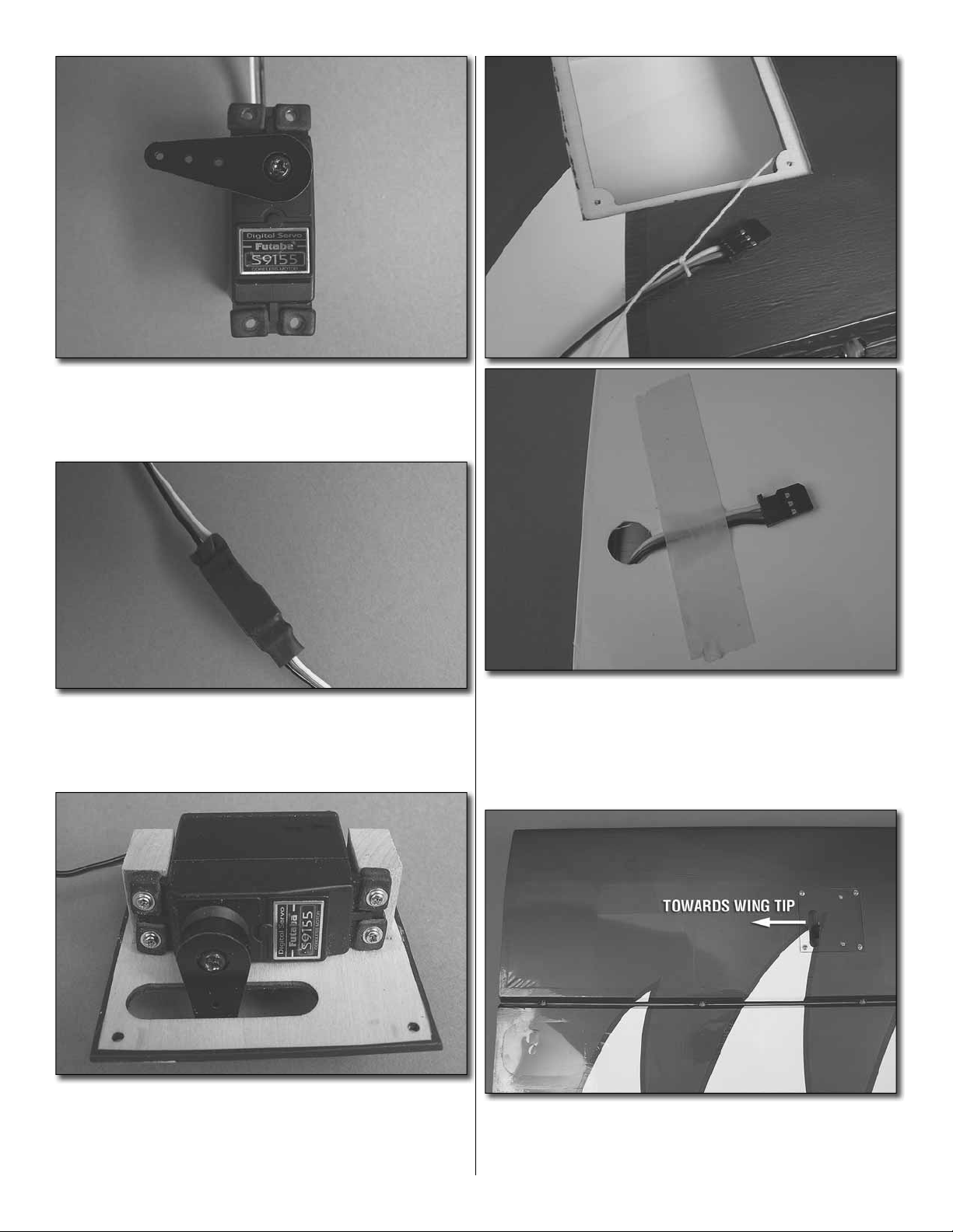
❏ ❏ ❏ ❏
servo. It’s recommended that you use an aluminum servo arm.
Many different brands are available but we used the Great
Planes 1" [25.4mm] aluminum servo arm (GPMM1100).
2. Install a 1" [25.4mm] servo arm onto your
❏ ❏ ❏ ❏
the servo lead. Secure the extension to the lead with tape,
a piece of shrink tube or some other method to keep them
from coming unplugged.
❏ ❏ ❏ ❏
blocks. Drill through the servo mounting holes with a 1/16"
[1.6mm] drill bit. Install the servo onto the servo cover using
the hardware included with your servo. Center the servo and
then install a servo arm as shown.
3. Install a 12" [305mm] servo extension onto
4. Place the servo onto the servo mounting
❏ ❏ ❏ ❏
string to the servo extension. Pull the string and the servo
lead through the wing. Untie the string from the lead and
insert the lead through the small hole on the top of the wing
at the root. Tape the lead to the wing to prevent it from falling
back into the wing.
❏ ❏ ❏ ❏
opening for the servo arm should be pointed towards the
wingtip. Mount the servo cover with #2 x 3/8" [9.5mm] washer
head screws.
7
5. Inside the servo bay a string is taped. Tie the
6. Place the servo cover onto the wing. The
Page 8
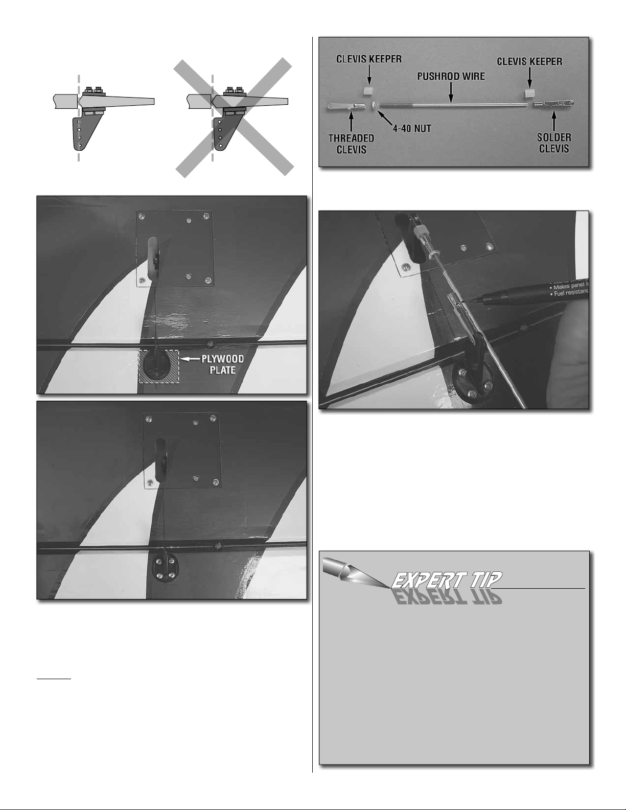
CORRECT INCORRECT
Hinge Line Hinge Line
❏ ❏ ❏ ❏
servo pushrod. Locate all the needed components.
8. The parts shown are required for making the
❏ ❏ ❏ ❏
hole in the servo arm. When positioned properly the control
horn will rest on a hardwood plate in the aileron. Mark the
location of the mounting holes onto the aileron. Drill a 3/32"
[2.4mm] hole on the marks, drilling through the plywood plate
but not through the top of the aileron. Attach the horn to the
aileron with four #4 x 1/2" [12.7mm] screws.
7. Place a nylon control horn in line with the outer
❏ ❏ ❏ ❏
the solder clevis to the aileron control horn. Center the aileron
and the aileron servo arm. Make a mark on the wire that aligns
with the front of the round portion of the clevis. Remove the
pushrod assembly from the servo. Cut the wire on the mark
and then solder the 4-40 solder clevis to the un-threaded
end of the pushrod wire. The following “Soldering Tip” may be
helpful if you are not familiar with soldering techniques.
1. Use denatured alcohol or other solvent to thoroughly
clean the pushrod. Roughen the end of the pushrod with
coarse sandpaper where it is to be soldered.
2. Apply a few drops of soldering fl ux to the end of the
pushrod, and then use a soldering iron or a torch to heat
it. “Tin” the heated area with silver solder by applying the
solder to the end. The heat of the pushrod should melt the
solder – not the fl ame of the torch or soldering iron – thus
allowing the solder to fl ow. The end of the wire should be
coated with solder all the way around.
9. Install the clevis to the servo arm and install
HOW TO SOLDER
8
Page 9
3. Place the clevis on the end of the pushrod. Add another
drop of fl ux, and then heat and add solder. The same as
before, the heat of the parts being soldered should melt
the solder, thus allowing it to fl ow. Allow the joint to cool
naturally without disturbing. Avoid excess blobs, but make
certain the joint is thoroughly soldered. The solder should
be shiny, not rough. If necessary, reheat the joint and allow
to cool.
4. Immediately after the solder has solidifi ed, but while it
is still hot, use a cloth to quickly wipe off the fl ux before
it hardens. Important: After the joint cools, coat the joint
with oil to prevent rust. Note: Do not use the acid fl ux that
comes with silver solder for electrical soldering.
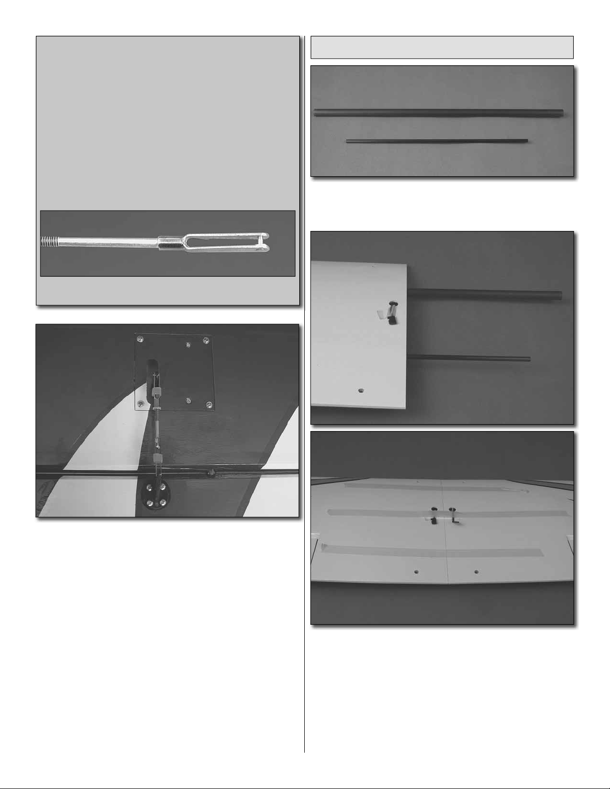
This is what a properly soldered clevis looks like – shiny
solder with good flow, no blobs and flux removed.
Join the Bottom Wing Panels
1. Locate the 1/4" x 12-1/4" [6.4mm x 311mm] and the
❏
1/2" x 17-3/4" [12.7mm x 450mm] composite tubes. Test fi t
them into the holes in the root rib.
10. Once the solder has cooled, install the pushrod to the
servo arm and the second hole from the end of the aileron
control arm. Be sure to slide the clevis keepers over the clevis
and tighten the 4-40 nut.
11. Repeat steps 1-10 for the lower left wing panel, the
❏
top right wing panel and the top left wing panel. Note: When
the servo leads get pulled through the top wings the leads
will exit out the holes in the bottom of the wing.
2. Mix 1/2 ounce [15 mL] of 30 minute epoxy. Apply epoxy
❏
into the tube holes in the right and left wings as well as the
root rib of each wing. Brush a thin fi lm of epoxy onto each
of the tubes and then insert the tubes into the right wing.
Remove excess glue that may have worked its way out of the
tube holes and then place the left wing onto the tubes and
slide the wings together. Clean excess epoxy from the wing
with rubbing alcohol and a paper towel. Tape the wing halves
together and then set the wing aside while the glue cures.
9
Page 10
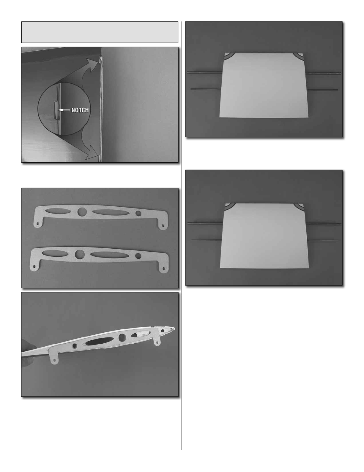
Join the Top Wing Panels with
the Wing Center Section
1. Trim the covering from the two notches on both ends of
❏
the top wing center section
3. Insert the 1/2" x 27-1/4" [12.7mm x 692mm] and the
❏
1/4" x 25" [6.4mm x 635mm] composite tube into the holes in
the center section of the top wing, centering the tubes.
2. Locate the two aluminum wing brackets. Test fi t them
❏
to the root rib at each end of the wing center section. When
positioned properly the aluminum rib will fi t fl ush to the end of
the wing center section and the tabs will fi t into the notches
in the end of the wing center section. When you are satisfi ed
with the fi t, epoxy the aluminum ribs to both ends of the wing
center section. Set it aside, allowing the glue to harden.
4. Use the same procedure used on the bottom wing to
❏
assemble the top wing. Mix 3/4 ounces [22mL] of 30 minute
epoxy. Pull the tubes out about 1" [25.4mm]. Brush a thin fi lm
of epoxy onto the tubes. Push the tubes back into the center
section with a twisting motion to spread the glue. Do this on
the other end of the wing center section. Apply epoxy into the
tube holes in the right and left wings as well as the root rib of
each wing. Brush a thin fi lm of epoxy onto each of the tubes
and then insert the tubes into the right wing. Remove excess
glue that may have worked its way out of the tube holes and
then place the left wing onto the tubes and slide the wings
together. Clean excess epoxy from the wing with rubbing
alcohol and a paper towel. Tape the wing halves together
and then set the wing aside while the glue cures.
10
Page 11
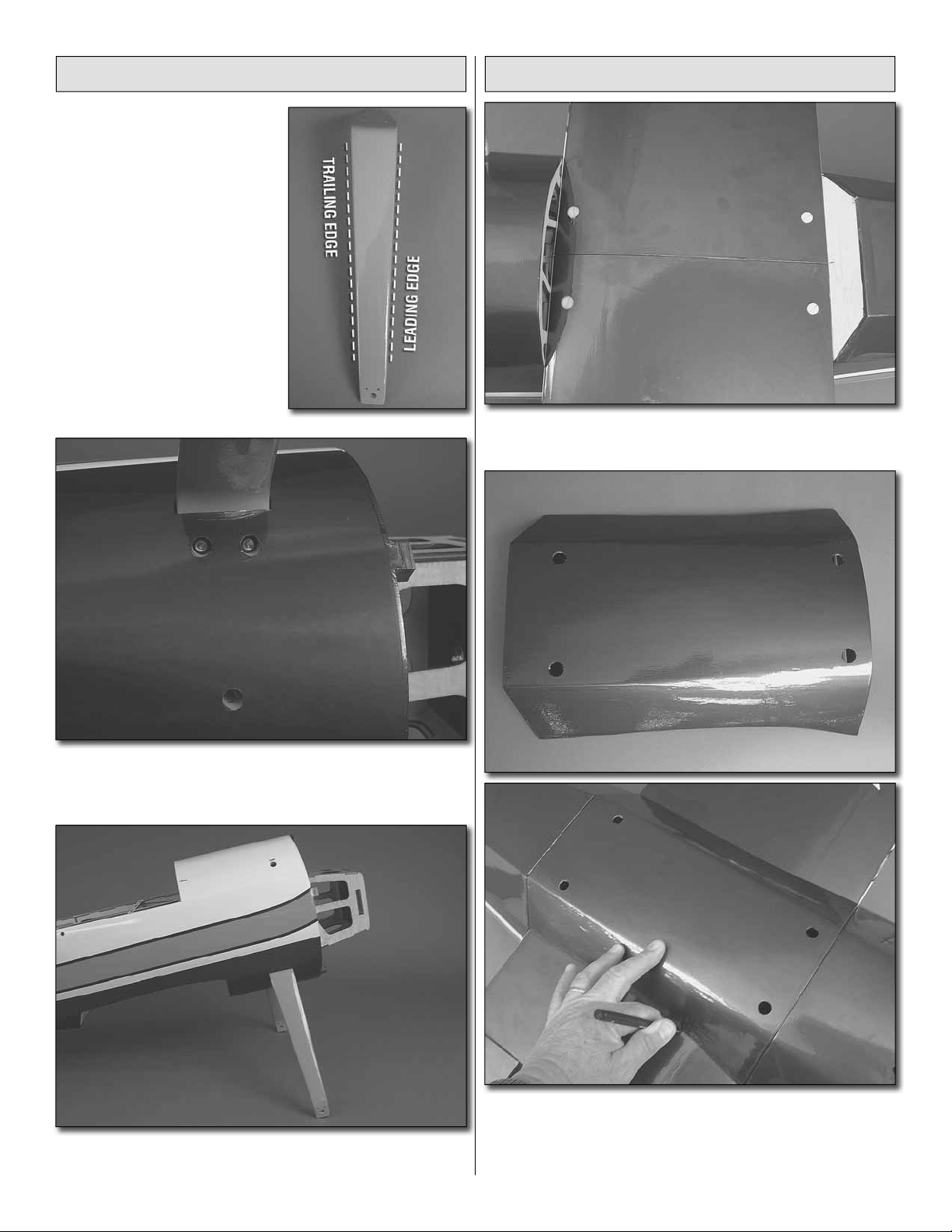
Install the Landing Gear
1. Look closely at the
❏ ❏
landing gear legs. You will
notice one side is straight and
the other is slightly angled. The
straight side is the leading edge
of the gear. Determine the right
gear from the left. Then insert
one of the gear legs into the slot
in the side of the fuselage.
Install the Upper and Lower Wings
1. Install the lower wing to the fuselage with four
❏
1/4-20 x 2" [51mm] nylon wing bolts.
2. Secure the landing gear to the fuselage with three
❏ ❏
8-32 x 3/4" [19.1mm] socket head cap screws, #8 lock
washers and a drop or two of thread locker.
3. Repeat this for the other landing gear leg.
❏
2. Locate the lower wing belly pan. Place in onto the
❏
bottom of the lower wing. Mark the outline of the belly pan to
the bottom of the wing with a fi ne tip felt marker.
11
Page 12
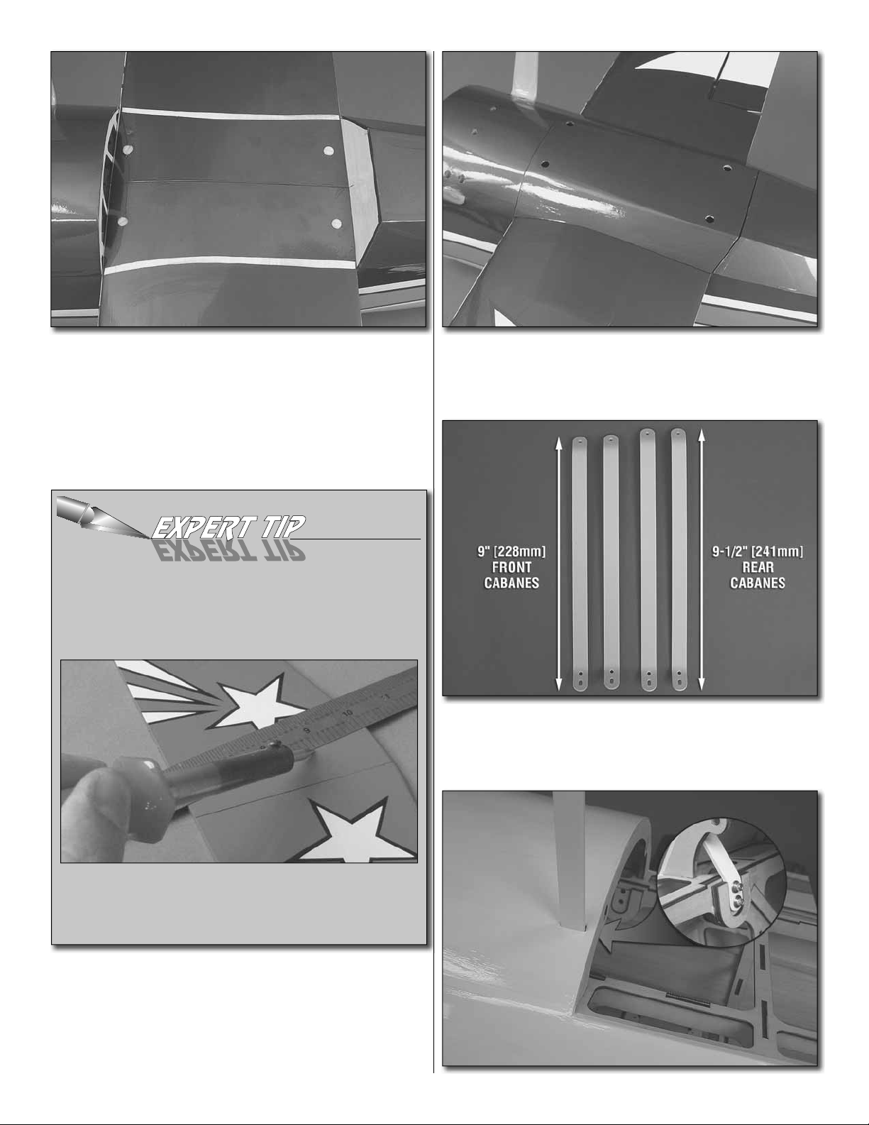
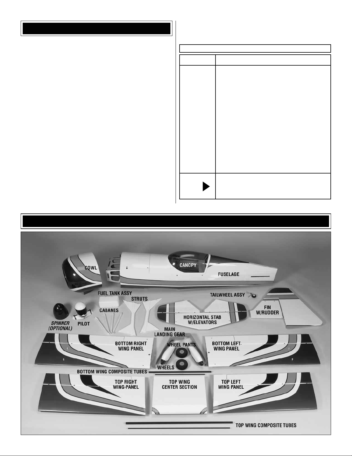
3. Using a sharp hobby knife or the method in the “Expert
❏
Tip” that follows, cut 1/4" [6.4mm] of covering inside the line
you have marked on the wing. Be careful to only cut through
the covering, not the wood.
HOW TO CUT COVERING FROM BALSA
Use a soldering iron to cut the covering from the stab. The
tip of the soldering iron doesn’t have to be sharp, but a fi ne
tip does work best. Allow the iron to heat fully.
4. Glue the belly pan to the lower wing. Once the glue
❏
has dried you may wish to remove the lower wing if you have
limited space in your shop. However, you will need to reinstall it again at step 8. The choice is yours.
5. Locate the four aluminum center cabanes. Two of
❏
them are 9" [228mm] long and two are 9-1/2" [241mm] long.
The longer two are the rear cabanes and the shorter are the
front cabanes.
Use a straightedge to guide the soldering iron at a rate that
will just melt the covering and not burn into the wood. The
hotter the soldering iron, the faster it must travel to melt a
fi ne cut. Peel off the covering.
12
Page 13

on each of the wings. Secure them with 4-40 x 1/2" [12.7mm]
socket head cap screws, #4 fl at washers and 4-40 lock nuts.
Do this for both wings. Once you are satisfi ed everything fi ts
well, remove the outer struts and the top wing. Leave the
bottom wing on the airplane.
Assemble and Install the Carry Handle
6. One end of the cabane has two holes. This is the end
❏
that gets inserted into the fuselage. Slide one of the long
cabanes in place into the rear slot in the fuselage. Secure the
cabane to the fuselage with two 4-40 x1/2" [12.7mm] socket
head cap screws, #4 lock washers and #4 fl at washers. Be
sure to apply a couple of drops of thread locker onto each
of the bolts. Do this for the remaining three cabanes, placing
the shorter cabanes in the forward slots.
7. Install the top wing onto the cabanes, securing it with
❏
four 4-40 x 1/2" [12.7mm] socket head cap screws, fl at
washers and a 4-40 nylon lock nuts.
We have included a carrying handle that we strongly advise
using when you are not fl ying the airplane. In addition to
providing a safe method for handling the airplane, it also
keeps the cabanes aligned and allows you to set the airplane
upside down.
8. If you do not have the lower wing mounted to the
❏
airplane do so now. Attach a fi berglass wing strut to the tabs
1. Locate the fi ve components of the carrying handle.
❏
Align and glue one of the side components with one of the
components with the hole in the center. Do this to create the
two side pieces.
13
Page 14

2. Place the side piece with the hole facing the bench.
❏
Insert a 4-40 blind nut into each corner of the parts.
4. Secure the handle to the cabane with a 4-40 x 1/2"
❏
[12.7mm] socket head cap screw and a #4 fl at washer.
3. Glue the hardwood handle into the hole as shown. Drill
❏
a 3/32" [2.4mm] hole through the end of each end, through
the handle and then screw a #4 x 1/2" [12.7mm] screw with
a #4 fl at washer into the hole you drilled.
14
Page 15

ASSEMBLE THE FUSELAGE
Install the Stab, Elevators,
Fin and Rudder
For the following steps you will need to have the bottom
wing attached to the fuselage. If you have removed the wing,
re-install it now.
wing. If you fi nd that your stab is not aligned, adjust the
stab by removing small amounts of the stab saddle with
100 grit sandpaper.
3. When you are satisfi ed everything is aligned properly,
❏
wick CA into the stab and the stab opening. Work slowly,
making sure that you apply adequate amounts of glue to
secure the stab. Leave the stab undisturbed while the glue
hardens. After the glue has dried you can remove the lower
wing from the fuselage. Leave the handle in place to keep
the cabanes secure while completing the remainder of
the construction.
1. The center of the stab has been left uncovered for an
❏
easier stab installation. Insert the stab into the opening in the
fuselage. Position the stab so that it is equal in length on both
sides of the fuselage and that the distance from the wing tip
to the stabilizer tip is equal.
2. Stand back a few feet and look at the stab in relation
❏
to the wing. The stab should be parallel and in line with the
4. Apply a drop of oil or work petroleum jelly to the center
❏
of the hinge. This will prevent glue from getting into the hinge
when you glue them in place.
15
Page 16

5. In a moment you will be instructed to install the hinges.
❏
These hinges have small fl anges on each side. When you
install the hinges into the control surface the fl ange must be
in line with the hinge line. And the center of the hinge should
be in line with the end of the control surface.
6. Apply 30-minute epoxy into the holes in the stab and
❏
onto one half of each of the hinges. Insert a hinge into each
of the holes in the stab. Apply glue into the holes in the
elevators and onto the other half of each hinge. Slide the
elevators onto the hinges, pressing them tightly against the
stab. Clean any excess epoxy with a paper towel and rubbing
alcohol. Allow the glue to fully harden.
7. Apply a light coat of epoxy to the exposed wood of the
❏
vertical fi n and inside the fi n slot at the back of the fuselage.
Slide the fi n into the slot. Clean any excess epoxy with a
paper towel and rubbing alcohol.
16
Page 17

8. Install the rudder and the rudder hinges using the
❏
same technique used for the elevators.
Install the Tail Braces
1. Your kit includes two different tail wire brackets. One
❏
bracket has a distinctly sharper angle than the other. The
eight brackets with the steeper angle attach to the top of the
stab and fi n. The four brackets with the shallow angle attach
to the bottom of the stab.
2. Install the brackets in the recesses in the stab and fi n.
❏
Secure the brackets with a 2-56 x 1/2" [12.7mm] machine
screw. Be sure to apply thread locker to the nut. Do this for
all of the brackets.
3. There is a plywood plate located on the bottom of the
❏
fuselage. You can see the outline of the plate if you look at
the covering at a slight angle. Use a pin to locate the predrilled holes in the plywood plate.
17
Page 18

4. Install the four-armed metal bracket to the bottom of the
❏
fuselage with two #4 x 1/2" [12.7mm] sheet metal screws.
5. There are four 6" [152mm] and four 9-3/4" [248mm]
❏
carbon rods, and sixteen brass couplers that form the tail
wires. Using 220 grit sandpaper, lightly sand 1/4" [6.4mm] on
each end of each rod.
8. Attach the long rods between the fi n and the top of the
❏
stab and install the shorter rods to the bottom of the stab and
the bottom of the fuselage. Adjust each rod so they are snug.
Back the nuts away from the clevis. Apply a drop of thread
locker to the threads and then tighten the nuts against the
clevis. Do this for all of the connectors. Once the nuts have
all been tightened against the clevis, slide the silicone clevis
keeper over the clevises.
Install the Wheels, Wheel Pants,
and Tail Wheel Assembly
6. Apply a small amount of CA glue to the end of the rod.
❏
Insert a brass coupler onto the end of the rod with a slight
twisting motion to help spread the glue in the coupler. Glue a
brass coupler to both ends of each of the eight carbon rods.
Allow the glue to thoroughly harden.
7. Install a 2-56 nut, silicon clevis keeper and a 2-56 metal
❏
clevis onto each of the threaded couplers.
1. Install a bolt-on axle into the hole in the landing gear.
❏ ❏
Apply thread locker to the threads of the axle. Then secure
the axle with the axle bolt. Be sure when installing the axle
that the fl at spot on the axle is facing the bottom of the
landing gear.
18
Page 19

and #4 fl at washer. If the wheel is not centered in the wheel
pant, adjust the wheel collars to allow the wheel to spin free
without touching the wheel pants.
4. Repeat these steps for the other wheel and wheel pant.
❏
2. Insert a 6-32 x 1/4" [6.4mm] socket head cap screw
❏ ❏
into two 3/16" [5mm] wheel collars. Be sure to apply a couple
of drops of thread locker to the screws. Slide a wheel collar
onto the axle followed by the wheel and another wheel collar.
Tighten one wheel collar against the fl at spot on the axle
and then tighten the other wheel collar against the wheel.
Be sure the wheel spins freely. Adjust the wheel collars as
needed to assure the wheel spins freely.
3. Slide the wheel pant over the wheel and axle.
❏ ❏
Attach the wheel pant to the landing gear with two
4-40 x 1/2" [12.7mm] socket head cap screws, #4 lock washer
5. Locate the nylon bushing and nylon pin. Glue the
❏
bushing into the hole in the back of the fuselage.
6. Glue the nylon pin into the hole in the rudder. Install the
❏
end of the pin without the hole into the rudder. The hole in
the pin should be in line with the rudder and the pin should
extend from the hole 1/4" [6.4mm].
19
Page 20

7. Slide the tail wheel wire through the hole in the bracket.
❏
Insert a 4-40 set screw into a 3/32" [2.4mm] wheel collar. Then
slide the wheel collar onto the tail wheel wire. Slide the tail
wheel wire into the nylon bearing. Center the bracket to the
fuselage. Mark the location of the bracket mounting holes onto
the fuselage and then remove the tail wheel wire. On the marks
you made, drill a 3/32" [2.4mm] hole through the plywood.
Install the Elevator and Rudder Servos
The following instructions will cover installation of the rudder
and elevator servos. For the elevator servos to work properly
your radio system must have the ability to adjust the servo
direction independently from each other. If your radio does
not have this capability you will need to purchase an after
market “in-line” servo reverser. For Futaba this is the SR-10
dual servo reverser (FUTM4150). A standard “Y”-connector
will not work properly.
1. Install a 24" [610mm] servo extension onto the servo
❏ ❏
lead. Secure the extension to the lead with tape, a piece of
shrink tube or some other method to keep them from coming
unplugged.
8. Bend the wire as needed to get a good alignment with
❏
the pin and then slide the end of the wire from the tail wheel
assembly into the hole in the nylon pin. Secure the tail wheel
assembly to the fuselage with two #4 x 1/2" [12.7mm] screws.
4-40 BOLT
BALL SWIVEL
4-40 NUT
2. Cut 1" [25.4mm] from the non-threaded end of two
❏ ❏
of the 4-40 x 6" [152mm] wire pushrods. Solder a 4-40 solder
clevis to the non-threaded end of the wires. Once the solder
has cooled install a silicone clevis keeper over the clevis.
Thread a nylon swivel ball link onto the threaded portion of
the wire. Enlarge the outer hole in a 1" [25.4mm] servo arm to
1/8" [3.2mm] to accommodate the bolt for the swivel connector.
Install the swivel ball link into the outer hole. Be sure to apply
a drop of thread locker to the threads of the bolt.
BRASS BUSHING
4-40 NUT
9. Slide the tail wheel onto the tail wheel wire and secure it
❏
in place with a 3/32" [2.4mm] wheel collar and 4-40 set screw.
❏ ❏
the servo.
20
3. Center the servo. Then, install the servo arm to
Page 21

4. Install the servo into the fuselage with the servo
❏ ❏
spline oriented towards the front of the fuselage. Secure the
servo with the hardware that came with the servo. Place a
nylon control horn in line with the servo arm. When positioned
properly the control horn will rest on a hardwood plate in the
elevator. Mark the location of the mounting holes onto the
elevator. Drill a 3/32" [2.4mm] hole on the marks, drilling
through the plywood plate but not through the top of the
elevator. Attach the horn to the elevator with four #4 x 1/2"
[12.7mm] screws.
5. Repeat steps 1-4 for the remaining elevator servo.
❏
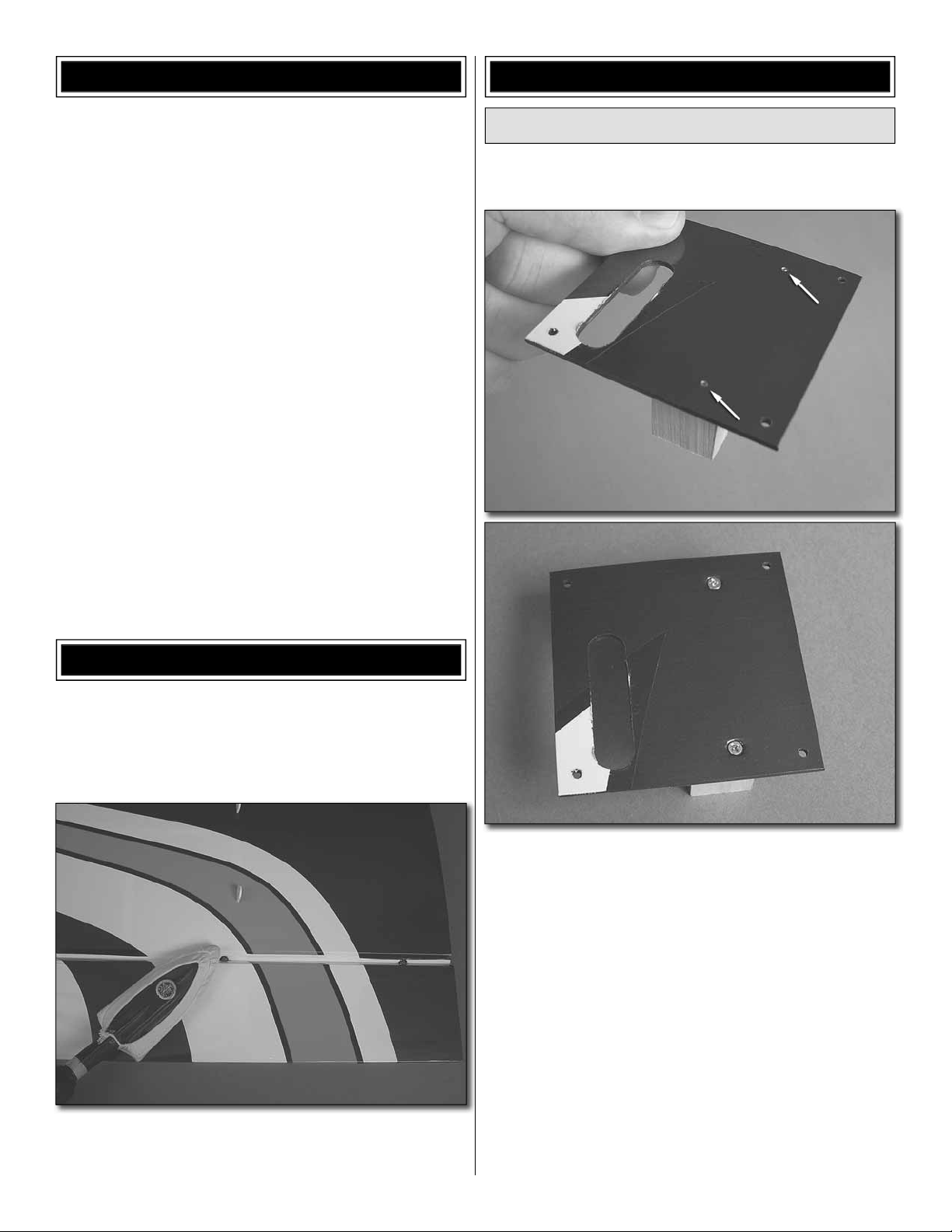
7. Two of the large black control horns need to be
❏
modifi ed in order to get full rudder defl ection. Using a Dremel
tool, modeling knife or other cutting tool, shape the control
horn to match the one shown. Drill the outer hole to 1/8"
[3.2mm] diameter.
4-40 THREADED
COUPLER
BRASS CRIMP
CONNECTOR
6. Locate the spool of .038 [.96mm] wire and cut it in
❏
half. Slide a brass crimp connector onto one end of the wire
followed by the threaded brass connector and then feed the
wire back through the crimp connector. Squeeze the crimp
connector fi rmly onto the wire to secure the threaded coupler
to the wire. Thread a 4-40 nut onto the coupler followed by
the nylon swivel ball link. Do this for both pieces of wire.
8. Position a control horn in line with the rudder pull-pull
❏
wire exit hole on the side of the fuselage and on the plywood
plate located in the rudder. Mark the location of the four
mounting holes for the control horn. On each of the marks
drill a 1/8" [3.2mm] hole through the plywood plate, drilling
completely through the rudder. Attach a control horn on each
side of the rudder using four 4-40 x 3/4" [19.1mm] machine
screws and four 4-40 nuts. Be sure you use thread locker on
each of the nuts.
21
Page 22

9. Install the rudder servo into the rear servo opening in
❏
the center of the fuselage with the hardware that came with
your servo. Install a 2.5" [64mm] double servo arm onto the
servo (GPMM1600) and then center the servo.
brass crimp connector and a threaded brass coupler to
each of the wires using the same technique used for the
connections to the rudder. (Adjust the wire until both wires
are tight before crimping the connector to the wire). Cut off
any excess wire. If the wire is not tight enough, adjust the
tension by turning the swivel ball link further in or out on the
threaded brass couplers.
Install the Engine and Throttle Servo
The instructions we have included for engine mounting
are for the Desert Aircraft DA-50 rear carb engine with 3"
[76mm] stand-offs. If you will be mounting a different brand
of engine you will have to modify your installation as needed
to accommodate your engine. Whether you will be installing a
DA-50 or another brand of engine, it is recommended you take
a few minutes to read these instructions prior to beginning
the installation so you can be familiar with the process we
recommend. We understand that “large scale” modelers have
many different preferences for hardware and methods for
installation. We have provided what we believe is a simple and
reliable installation. Feel free to substitute different hardware
or use other installation methods you may prefer.
10. Slide the wire cable with the swivel ball link into
❏
the hole in the fuselage until all of the wire is inside of the
fuselage. Attach the nylon swivel ball link to the outer hole in
the control horn the same as was done for the elevators.
11. Drill the outer holes of the servo arm to 1/8" [3.2mm].
❏
Install a swivel ball link to both ends of the arm. Attach a
1. Cut out the engine mounting pattern located on the
❏
back cover of this manual. Tape the pattern in place, aligning
it with the reference lines etched into the fi rewall. Notice the
pattern has an arrow on it that references “UP”. The arrow
should be pointed towards the top of the fuselage. This
pattern will provide the proper mounting holes for an inverted
engine installation.
2. On each of the reference marks drill a 5/64" [2mm] pilot
❏
hole. With your pilot hole as a reference, drill each hole the
size indicated on the pattern.
22
Page 23

3. Mount the engine with the hardware that came with
❏
the engine.
4. Install a ball link on both the choke arm and the
❏
carburetor arm. We have included both .080 and a 2-56
threaded balls, washer and nuts. Choose whichever one
best fi ts the hole in the arms. Be sure that you use thread
locker on the threads.
5. Locate two plywood throttle pushrod supports. Glue
❏
the longest support to the former shown in the photograph,
aligning it with the edge of the fuel tank tray.
6. Glue the remaining support inside of the fuselage
❏
as shown.
23
Page 24

9. Install the brass bushing into the nylon bellcrank.
❏
Screw the bellcrank assembly to the wood block with a
#4 x 1/2" [12.7mm] screw. Be sure to orient the bellcrank
arm as shown. Enlarge the outer hole in both ends of the
bellcrank with a 5/64" [2mm] drill bit.
10. Locate a 2-56 x 6" [152mm] wire pushrod. Cut the
❏
threads so only 3/8" [9.5mm] of thread remain. Cut the
unthreaded end of the wire so that the overall length of
the wire pushrod including the remaining thread is 4-7/16"
[112mm]. Bend the un-threaded end of the wire 1/4" [6.4mm]
from the end of the wire. Screw a nylon ball link onto the
threaded end of the wire. Screw the nylon ball on so that it
completely covers the threads.
7. Cut the white plastic throttle pushrod tube to a length of
❏
13-3/4" [350mm] Roughen one end of the tube with 220 grit
sandpaper. Slide the tube into the throttle hole (the top hole)
in the fi rewall and into the holes in the two throttle pushrod
supports. Apply glue to the roughened end of the pushrod
tube. Then position the tube fl ush with the fi rewall. Apply a drop
of CA glue where the tube passes through the supports.
8. Locate the 3/4" x 3/4" x 1" [19mm x 19mm x 25mm]
❏
hardwood block. On the side that is 1" [25.4mm] long, drill a
3/32" [2.4mm] hole in the center of the block.
11. Install the pushrod wire as shown. Slide the bent end
❏
of the wire into the lower hole in the fi rewall. Attach the nylon
ball link onto the ball on the choke arm. Position the bellcrank
assembly inside the fuselage. Attach the pushrod from the
choke to the outer hole in the bellcrank and secure it with
a nylon FasLink™. Move the choke am back towards the
fi rewall. Now position the block so the other arm is positioned
as shown in the photograph. Glue the block in place with CA
glue. Once the glue has hardened drill two 1/16" [1.6mm]
holes in the fi rewall box and into the block. Install a #2 x 3/8"
[9.5mm] wood screw into each of the holes you drilled.
24
Page 25

12. Drill a 3/32" [2.4mm] hole directly below the bellcrank
❏
arm. Cut 1" [25.4mm] of threads from the end of a 2-56x12"
[305mm] pushrod wire (Save this piece of thread to be used
in the next step). Make a 90° bend 1/4" [6.4mm] from the end
of one end of the wire. Slide the wire into the hole you drilled
and then install the bent end of the wire into the outer hole of
the other bellcrank arm. Secure it with a nylon FasLink.
13. Cut the 24" [610mm] white fl exible pushrod to a
❏
length of 16" [406mm]. Thread the 1" [25.4mm] thread (that
you previously cut from the wire) into one end of the fl exible
pushrod and screw a nylon ball link onto the end. From a
6" [152mm] 2-56 pushrod wire cut 1/2" [12.7mm] of the
thread off. Then, on the other end of the fl exible pushrod,
screw the pushrod wire into it. Slide the pushrod into the tube
installed in the fi rewall. Snap the ball link onto the ball on the
throttle arm.
This bellcrank allows you to access the choke mechanism
from the bottom of the fuselage using the wire you just
installed. The wire extends below the fuselage further than
what you might want. Later, after the cowl is completely
installed, cut the wire to the length you wish. You may also
want to make a bend in the wire to give you something to
easily grab onto for activating the choke.
14. Install the throttle servo into the servo opening on the
❏
left side of the fuselage with the hardware that came with
the servo. Trim three arms from a four-armed servo horn.
Enlarge the outer hole in the servo arm with a 5/64" [2mm]
drill bit. Center the servo arm and the throttle barrel. Make
a mark on the wire where it passes over the hole. Make a
90 degree bend on the mark. Secure the wire with a nylon
FasLink and then cut off the excess wire.
25
Page 26

we found that there was room at the front of the fuselage.
We recommend that you use a heavy-duty switch such as
the Futaba heavy-duty charge switch (FUTM4385) and the
Ernst charge receptacle (ERNM3001). When determining a
location for the switch make sure you keep it as close to the
engine as possible to prevent any possible interference with
your radio system.
Install the Fuel Tank
15. Cut a piece of 1/4" [6.4mm] foam rubber to fi t under
❏ ❏
the ignition module. Place the module onto the fi rewall box.
On each side of the ignition module drill a 1/16" [1.6mm]
hole. Locate a 1/4" x 1/4" x 1/4" [6.4 x 6.4 x 6.4mm] hardwood
block and glue it to the fi rewall box under the hole you drilled.
Drill a 1/16" [1.6mm] hole through the hole you drilled and
into the block. Screw a hook into each off the holes you
just drilled. Secure the ignition module with a couple of #64
rubber bands (not included).
For the installation of the fuel tank you will need approximately
60" [1524mm] of tygon fuel tubing (not included). Be sure you
have this before proceeding with the next set of instructions.
1. Solder a fuel line barb onto one end of each of the
❏
three tubes.
16. Repeat step 15 for the ignition battery.
❏
17. You need to decide where you wish to put the switch and
❏
charge jack for the ignition module. Though it is a bit tedious
2. Assemble the stopper, tubes and metal plates. Solder
❏
another fuel line barb onto the ends of the short tubes. Bend
the brass vent/overfl ow tube upward so it will be at the top
of the tank.
26
Page 27

VENT/PRESSURE
(OR OVERFLOW)
One line is for
fueling/defueling
and the other is
for fuel pickup to
the carburetor (it
doesn’t matter which).
3. Connect the fuel tubing to the short tubes and the
❏
clunks–cut the lines so that the clunks cannot contact the
back of the tank–otherwise they could get stuck. Note that
one of the lines will be used for fueling and defueling and the
other line will be the pickup line that goes to the carburetor.
The bent tube will be the vent/overfl ow line that will be
connected to a line that exits the bottom of the fuselage.
Important: Secure both ends of both fuel tubes with small
nylon ties. This is an important measure that must be taken
to be sure the lines remain attached inside the tank.
6. Inside of the fuselage you will fi nd two slots on both
❏
sides of the fuel tank tray. Install a long tie wrap through the
slots and then put the tank in position on the tray. (If you wish
to put foam under the tank do this now). Pull the tie wraps
around the tank, making sure that the tie wrap falls into the
recesses in the tank. Pull the tie wraps tight and then cut off
the excess tie wrap material.
4. Write “TOP” on the back of the tank so you will know
❏
which way to install it after inserting the stopper assembly.
Insert the stopper so the vent tube will be at the top of the
tank. Then tighten the screw to squish the stopper and seal
the tank. Shake the tank to make sure the clunks can move
around and the fuel lines are not too long.
5. Install 13" [330mm] of fuel tubing onto each of the lines
❏
coming from the fuel tank. Be sure to put a tie wrap on each
of them.
7. Determine the location for the fuel line to come through
❏
the fi rewall and then drill a hole appropriate to the size of
your fuel line. Install the fuel line to the carburetor and route
the remaining fuel line out the bottom of the mounting box.
27
Page 28

8. Locate the 3mm plywood components that make up the
❏
fuel line holder. Glue the two matching parts to each other.
Then slide the remaining part into the slots, gluing it to the
other part.
10. Install an aluminum fuel plug into the fi ll line and then
❏
push the lines onto the holder.
11. Place a piece of masking tape on the fuselage in line
❏
with each of the wood cowl mounting blocks. Measure back
1" [25.4mm] from the center of each block. Mark a line onto
the tape.
9. Glue the fuel line holder to the bottom of the fi rewall.
❏
12. Place the cowl onto the fuselage, aligning the stripes
❏
on the cowl with the fuselage. Make a mark on the cowl
where the throttle choke wire contacts the cowl and then cut
away the cowl as needed to provide clearance for the wire.
Tape the cowl in place on the front of the fuselage.
28
Page 29

13. Using the line on the tape as your reference, measure
❏
forward from the end of the line 1" [25.4mm]. Make a mark
on the cowl and do this for each of the lines you made. On
the mark you made drill a 3/32" [2.3mm] hole through the
cowl and into the cowl blocks. Temporarily install the cowl to
the fuselage with #4 x 1/2" [12.7mm] screws. (Don’t worry
about washers for now. You will be removing the cowl several
times for fi nal adjustments to the cowl).
14. Make cut outs in the cowl for any parts of the engine
❏
that might be interfering with the cowl (spark plug boot,
muffl er, etc.)
15. Locate the ABS plastic engine baffl e. Place it in front
❏
of the cowl and mark the location of the cylinder head. Cut
this area from the baffl e. This opening will allow air to pass
over the cylinder allowing the engine to be cooled.
16. Slide the engine baffl e into the front of the cowl. Install
❏
a tip extension onto a bottle of medium CA glue. Now, center
the baffl e in the front of the cowl and while holding the engine
baffl e in place, tack glue the baffl e to the cowl with the CA
glue. Use a CA glue accelerator to harden the glue quickly.
Tack the baffl e in place in three or four spots. When you have
the baffl e centered and secured, remove the cowl.
29
Page 30

17. Where the baffl e contacts the cowl, wipe that area
❏
with a paper towel dampened with alcohol. Let the alcohol
dry and then mix an ounce [30mL] of 5-minute epoxy and
micro balloons. Apply a fi llet of the epoxy mixture around the
baffl e where it contacts the cowl to permanently secure the
baffl e. Allow the glue to harden.
spinner is available as an accessory item from Great Planes
(GPMA4020). This is a high-quality, turned aluminum spinner
that has a scale shape and matching color to the airplane.
Completing the Radio Installation
At this point you should have all of the servos installed. All
that remains is installing the receiver, battery, switch harness
and two aileron extensions.
18. To allow for proper engine cooling you must have an
❏
area to allow the air to escape the cowl. Cut two openings as
shown. Each of the openings should measure approximately
1" x 5" [25.4mm x 127mm].
1. There is a hole located where the forward cabane comes
❏
through the surface of the fuselage. Insert a 24" [610mm]
servo extension into each hole and guide it toward the radio
compartment in the fuselage. These extensions are for the
ailerons in the upper wing. There are a number of ways that
you can secure the extensions. We cut 1/4" [6.4mm] bands
of heat shrink tubing, slipped them over the extension and
the cabane and then shrunk the bands with a heat gun. You
can secure the extensions with tape or even use hot glue.
Secure both wires to the cabane.
19. Re-install the cowl to the fuselage with the screws
❏
and #4 fl at washers. Install the propeller and spinner. The
2. Cut the 24" [610 mm] Velcro strap to fi t your particular
❏
battery. Use the Velcro to secure the battery pack as shown.
30
Page 31

3. Install the switch and charge jack for your radio system.
❏
We recommend that you use a heavy-duty switch such as
the Futaba heavy-duty charge switch (FUTM4385) and the
Ernst charge receptacle (ERNM3001).
6. Plug all of the servo leads into the appropriate channels
❏
in the receiver. Depending on your transmitter you may wish
to use separate channels for each of the four ailerons. For
our set up we used “Y” connectors to have the ailerons in two
channels. You can also use “Y” connectors to have all four
servos work in one channel. Refer to your radio manual for
the best use of the radio channels.
Install the Cockpit and Pilot
4. Install the receiver to the fuselage. Follow the instructions
❏
for antenna installation that came with your brand of receiver.
Be sure to place it on a cushion of 1/4" [6.4mm] foam. Secure
it with tie wraps or Velcro.
5. We used a 2.4GHz radio system. If you are going to use
❏
a 72MHz receiver, we have installed a tube for the antenna.
Route the antenna into the tube.
1. The pilot comes in two parts. Using 220-grit sandpaper,
❏
scuff the fi nish on the top of the neck and the bottom of the
head. Glue the head to the body with epoxy.
31
Page 32

2. On the bottom of the pilot are two holes and inside
❏
the pilot there are blind nuts to secure the pilot. Align the
holes on the bottom of the pilot with the holes located at
the back of the cockpit. Secure the pilot to the cockpit with
4-40 x 1/2" [12.7mm] machine screws, #4 fl at washers and
#4 lock washers.
3. Included in the kit is a cockpit fl oor. To keep some of the
❏
weight down you might choose not to install it. Installation is
completely optional. If you wish to install the fl oor, glue it in
place on the bottom of the cockpit canopy.
4. Install the canopy to the fuselage. Secure the canopy
❏
with four 4-40 x 3/4" [19.1mm] and four #4 fl at washers. Be
sure to use threadlocker on the screw.
32
Page 33

Apply the Decals
GET THE MODEL READY TO FLY
Check the Control Directions
1. Turn on the transmitter and receiver and center the
❏
trims. If necessary, remove the servo arms from the servos
and reposition them so they are centered. Reinstall the
screws that hold on the servo arms.
2. With the transmitter and receiver still on, check all the
❏
control surfaces to see if they are centered. If necessary,
adjust the clevises on the pushrods to center the control
surfaces.
4-CHANNEL RADIO SET UP
(STANDARD MODE 2)
RIGHT AILERON
RUDDER
MOVES
RIGHT
MOVES UP
LEFT AILERON
MOVES DOWN
1. The decals are all pre-cut. Simply remove the decal from
the sheet.
2. Be certain the model is clean and free from oily fi ngerprints
and dust. Prepare a dishpan or small bucket with a mixture
of liquid dish soap and warm water—about one teaspoon of
soap per gallon of water. Submerse the decal in the soap and
water and peel off the paper backing. Note: Even though the
decals have a “sticky-back” and are not the water transfer
type, submersing them in soap & water allows accurate
positioning and reduces air bubbles underneath.
3. Position decal on the model where desired. Holding the
decal down, use a paper towel to wipe most of the water
away.
4. Use a piece of soft balsa or something similar to squeegee
remaining water from under the decal. Apply the rest of the
decals the same way.
FULL
THROTTLE
3. Make certain that the control surfaces and the carburetor
❏
respond in the correct direction as shown in the diagram.
If any of the controls respond in the wrong direction, use
the servo reversing in the transmitter to reverse the servos
connected to those controls. Be certain the control surfaces
have remained centered. Adjust if necessary.
ELEVATOR
MOVES DOWN
33
Page 34

Set the Control Throws
These are the recommended control surface throws:
To ensure a successful fi rst fl ight, set up your Pitts M-12s
according to the control throws specifi ed in this manual.
The throws have been determined through actual fl ight
testing and accurate record-keeping, allowing the model
to perform in the manner in which it was intended. If, after
you have become accustomed to the way the Pitts M-12s
fl ies, you would like to change the throws to suit your
taste, that is fi ne. However, too much control throw could
make the model too responsive and diffi cult to control, so
remember, “more is not always better.”
1. Use a box or something similar to prop up the bottom
❏
of the fuselage so the horizontal stabilizer and wing will be
level.
Measure the high rate elevator throw fi rst…
2. Hold a ruler vertically on your workbench against the
❏
widest part (front to back) of the trailing edge of the elevator.
Note the measurement on the ruler.
3D RATE
Up
Down
ELEVATOR
2-7/8"
[73mm]
Right
RUDDER
[152
AILERONS
[51
Note: The use of exponential will make the plane less sensitive at the center of
the control gimbals on the radio. We programmed -40% exponential on our
Futaba radios. Check your manufacturer’s instructions for exponential settings.
You may need to program positive exponential instead of negative exponential
as is done for Futaba radios.
In addition to exponential we found a 13% rudder to aileron mix helped to
minimize roll coupling in knife edge flight.
29°
6"
30°
Up
2"
mm
33°
mm
2-7/8"
[73mm]
29°
Left
6"
]
[152mm]
30°
Down
2"
]
[51mm]
33°
HIGH RATE
Up
Down
1-1/4"
[32mm]
Right
12°
1-1/4"
[32mm]
12°
Left
3"
mm
]
14°
Up
[76mm]
14°
Down
[76
1"
[25
mm
]
[25mm]
16°
16°
3"
1"
LOW RATE
Up
Down
1"
[25mm]
[25mm]
10°
Right
2"
mm
]
[51
[51mm]
10°
Up
Down
3/4"
[19
mm
]
[19mm]
12°
1"
10°
Left
2"
10°
3/4"
12°
3. Move the elevator up with your transmitter and move the
❏
ruler forward so it will remain contacting the trailing edge. The
distance the elevator moves up from center is the “up” elevator
throw. Measure the down elevator throw the same way.
4. Referring to the Proper Pushrod Hookup illustrations
❏
on the opposite page, adjust the location of the pushrod
on the servo arm or on the elevator horn and program the
ATVs in your transmitter to increase or decrease the throw
according to the measurements in the control throws chart.
5. Measure and set the low rate elevator throws and the
❏
high and low rate throws for the rest of the control surfaces
the same way.
NOTE: The throws are measured at the widest part of the
elevators, rudder and ailerons.
The following are general guidelines for hooking up
pushrods to the control surface and the servo. The
installation method used throughout this manual
provided safe, effective control and allows you to
achieve all of the required control throws. If for some
reason you have decided to hook up the controls
differently than we outlined, please review the following
to assure you have a safe set up.
34
Page 35

Proper Pushrod Hookup; Avoiding Flutter, Maximizing Servo Output Torque
Note: Your control horn may vary.
SERVO ARM
Pivot point
OFFSET
When connecting pushrods and setting up your control throws, it is critically important to use proper pushrod geometry—that is the
distance from the pushrod on the servo arm to the center of the output shaft (servo arm offset) compared to the distance from the
pushrod on the control horn to the pivot point (control horn offset).
Long
EXTREMELY DANGEROUS PUSHROD HOOKUP
CONTROL
HORN OFFSET
distance
Short
distance
Pushrod far out
on the servo arm…
One particularly dangerous situation arises when the pushrod on the servo arm is too “far out” and the pushrod on the control horn is too
“close in.” This setup is usually chosen by pilots who are trying to achieve maximum, “monster” control throws for 3D fl ight. But with your
pushrods set up this way, any free play (slop) in the linkages or servo will be greatly magnifi ed, possibly causing destructive control surface
fl utter. Additionally, if you have to turn your ATVs way down for “normal” throw, the result will be poor resolution and poor servo holding/
centering capabilities. More importantly, too much force may be transmitted back to the servo, possibly causing control surface blowback,
stripped servo gears or stripped servo arms—the latter two likely causing a crash.
…pushrod close in
on the control horn.
PREFERRED PUSHROD HOOKUP
“Closest in”
on servo arm
Here is an optimum pushrod setup—the pushrod is “close in” on the servo arm and “far out” on the control horn. This situation gives the
greatest mechanical advantage of the servo over the control surface which will increase the servo’s centering capabilities and output
torque, minimize any free play in the system and allow high ATV settings for optimum servo resolution and positive control “feel.” Note:
When the pushrod is “close in” on the servo arm, make certain the servo arm can travel through its full range of movement without the
pushrod (or clevis or other type of connector) interfering with the servo arm, output shaft or servo case.
“Farthest out”
on control horn
ACCEPTABLE PUSHROD HOOKUP
Move the pushrod farther out
on the servo arm…
If the optimum situation doesn’t provide enough control throw, the pushrod may be moved inward on the control horn, but it’s better to go
farther out on the servo arm because this will introduce less free play than the alternative. Only after moving the pushrod all the way out on
the servo arm, if you still can’t get the throw required, you’ll have to resort to moving the pushrod closer in on the control horn. Note: If you
have a computer radio, it is always desirable to set your ATVs to 100% (or as near 100% as possible to achieve the control throw required).
If setting up a model that requires extraordinary control surface throw (for 3D fl ying for example), start by “maxing-out” your ATVs (typically
130% -- 140%). Then, the dual rates in your “normal” fl ight mode will still be acceptably high (70% -- 80%) for good servo resolution.
…But leave the pushrod in the farthest out
location on the control horn.
35
Page 36

Balance the Model (C.G.)
More than any other factor, the C.G. (center of gravity/
balance point) can have the greatest effect on how a model
fl ies and could determine whether or not your fi rst fl ight will
be successful. If you value your model and wish to enjoy it
for many fl ights, DO NOT OVERLOOK THIS IMPORTANT
PROCEDURE. A model that is not properly balanced may
be unstable and possibly unfl yable.
At this stage the model should be in ready-to-fl y condition
with all of the components in place including the complete
radio system, engine, muffl er, propeller, spinner and pilot
(the fuel tank should be empty).
6" [152mm]
3. If the tail drops, the model is “tail heavy.” If possible,
❏
move the battery pack and/or receiver forward to get the
model to balance. If the nose drops, the model is “nose
heavy.” If possible, move the battery pack and/or receiver aft.
If the receiver and/or battery cannot be moved, or if additional
weight is still required, nose weight or tail weight may be
added. Use Great Planes “stick-on” lead (GPMQ4485). To
fi nd out how much weight is required, place incrementally
increasing amounts of weight on the top of the fuselage
over the location where it would be mounted inside until the
model balances. A good place to add stick-on nose weight
is to the fi rewall. Do not attach weight to the cowl—this will
cause the mounting screws to open up the holes in the cowl.
Once you have determined the amount of weight required,
it can be permanently attached. If required, tail weight may
be added by cutting open the bottom of the fuse and gluing
it permanently inside.
Note: If mounting weight where it may be exposed to fuel
or exhaust, do not rely upon the adhesive on the back to
permanently hold it in place. Over time, fuel and exhaust
residue may soften the adhesive and cause the weight to
fall off. Instead, permanently attach the weight with glue
or screws.
1. Use a fi ne-point felt tip pen to mark lines on the bottom
❏
of the top wing 6" [152mm] back from the leading edge of the
center section of the top wing. Apply narrow (1/16" [1.6mm])
strips of tape over the lines so you will be able to feel them
when lifting the model with your fi ngers.
This is where your model should balance for the fi rst
fl ights. Later, you may experiment by shifting the C.G. 1/4"
[6.4mm] forward or 1/2" [12.7mm] back to change the fl ying
characteristics. Moving the C.G. forward will improve the
smoothness and stability, but the model will then be less
aerobatic (which may be fi ne for less-experienced pilots).
Moving the C.G. aft makes the model more maneuverable
and aerobatic for experienced pilots. In any case, start at
the recommended balance point and do not at any time
balance the model outside the specifi ed range.
4. IMPORTANT: If you found it necessary to add any weight,
❏
recheck the C.G. after the weight has been installed.
Balance the Model Laterally
1. With the wing level, have an assistant help you lift the
❏
model by the engine propeller shaft and the bottom of the
fuse under the TE of the fi n. Do this several times.
2. If one wing always drops when you lift the model, it
❏
means that side is heavy. Balance the airplane by adding
weight to the other wing tip. An airplane that has been
laterally balanced will track better in loops and other
maneuvers.
2. With the wing attached to the fuselage, all parts of the
❏
model installed (ready to fl y) and an empty fuel tank, lift it at
the balance point you marked.
36
Page 37

PREFLIGHT
Identify Your Model
No matter if you fl y at an AMA sanctioned R/C club site or if
you fl y somewhere on your own, you should always have your
name, address, telephone number and AMA number on or
inside your model. It is required at all AMA R/C club fl ying sites
and AMA sanctioned fl ying events. Fill out the identifi cation
tag on this page and place it on or inside your model.
Charge the Batteries
Follow the battery charging instructions that came with your
radio control system to charge the batteries. You should
always charge your transmitter and receiver batteries the night
before you go fl ying, and at other times as recommended by
the radio manufacturer.
CAUTION: Unless the instructions that came with your
radio system state differently, the initial charge on new
transmitter and receiver batteries should be done for 15
hours using the slow-charger that came with the radio
system. This will “condition” the batteries so that the next
charge may be done using the fast-charger of your choice.
If the initial charge is done with a fast-charger the batteries
may not reach their full capacity and you may be fl ying with
batteries that are only partially charged.
Balance Propellers
Ground Check and Range Check
Run the engine for a few minutes to make sure it idles reliably,
transitions smoothly and maintains full power indefi nitely.
Afterward, shut the engine off and inspect the model closely,
making sure all fasteners, pushrods and connections have
remained tight and the hinges are secure. Always ground
check the operational range of your radio before the fi rst fl ight
of the day following the manufacturer’s instructions that came
with your radio. This should be done once with the engine off
and once with the engine running at various speeds. If the
control surfaces do not respond correctly, do not fl y! Find and
correct the problem fi rst. Look for loose servo connections
or broken wires, corroded wires on old servo connectors,
poor solder joints in your battery pack or a defective cell, or a
damaged receiver crystal from a previous crash.
ENGINE SAFETY PRECAUTIONS
Failure to follow these safety precautions may result
in severe injury to yourself and others.
• Keep all engine fuel in a safe place, away from high heat,
sparks or fl ames, as fuel is very fl ammable. Do not smoke
near the engine or fuel; and remember that engine exhaust
gives off a great deal of deadly carbon monoxide. Therefore
do not run the engine in a closed room or garage.
• Get help from an experienced pilot when learning to operate
engines.
• Use safety glasses when starting or running engines.
• Do not run the engine in an area of loose gravel or sand;
the propeller may throw such material in your face or eyes.
• Keep your face and body as well as all spectators away
from the plane of rotation of the propeller as you start and
run the engine.
• Keep these items away from the prop: loose clothing, shirt
sleeves, ties, scarfs, long hair or loose objects such as
pencils or screwdrivers that may fall out of shirt or jacket
pockets into the prop.
• Use a “chicken stick” or electric starter to start the engine.
Do not use your fi ngers to fl ip the propeller.
• Make all engine adjustments from behind the rotating
propeller.
• The engine gets hot! Do not touch it during or right after
operation. Make sure fuel lines are in good condition so fuel
will not leak onto a hot engine, causing a fi re.
Carefully balance your propeller and spare propellers before
you fl y. An unbalanced prop can be the single most signifi cant
cause of vibration that can damage your model. Not only
will engine mounting screws and bolts loosen, possibly with
disastrous effect, but vibration may also damage your radio
receiver and battery. Vibration can also cause your fuel to
foam, which will, in turn, cause your engine to run hot or quit.
We use a Top Flite Precision Magnetic Prop Balancer
(TOPQ5700) in the workshop and keep a Great Planes
Fingertip Prop Balancer (GPMQ5000) in our fl ight box.
37
Name
Address
City, State, Zip
This model belongs to:
AMA Number
Phone Number
Page 38

AMA SAFETY CODE (EXCERPTS)
CHECK LIST
Read and abide by the following excerpts from the Academy
of Model Aeronautics Safety Code. For the complete Safety
Code refer to Model Aviation magazine, the AMA web site or
the Code that came with your AMA license.
General
1) I will not fl y my model aircraft in sanctioned events, air shows,
or model fl ying demonstrations until it has been proven to be
airworthy by having been previously, successfully fl ight tested.
2) I will not fl y my model aircraft higher than approximately
400 feet within 3 miles of an airport without notifying the
airport operator. I will give right-of-way and avoid fl ying in the
proximity of full-scale aircraft. Where necessary, an observer
shall be utilized to supervise fl ying to avoid having models fl y
in the proximity of full-scale aircraft.
3) Where established, I will abide by the safety rules for the
fl ying site I use, and I will not willfully and deliberately fl y my
models in a careless, reckless and/or dangerous manner.
5) I will not fl y my model unless it is identifi ed with my name
and address or AMA number, on or in the model. Note: This
does not apply to models while being fl own indoors.
7) I will not operate models with pyrotechnics (any device
that explodes, burns, or propels a projectile of any kind).
Radio Control
1) I will have completed a successful radio equipment ground
check before the fi rst fl ight of a new or repaired model.
2) I will not fl y my model aircraft in the presence of spectators
until I become a qualifi ed fl ier, unless assisted by an
experienced helper.
3) At all fl ying sites a straight or curved line(s) must be
established in front of which all fl ying takes place with the
other side for spectators. Only personnel involved with fl ying
the aircraft are allowed at or in the front of the fl ight line.
Intentional fl ying behind the fl ight line is prohibited.
4) I will operate my model using only radio control frequencies
currently allowed by the Federal Communications Commission.
5) I will not knowingly operate my model within three
miles of any pre-existing fl ying site except in accordance
with the frequency sharing agreement listed [in the
complete AMA Safety Code].
9) Under no circumstances may a pilot or other person
touch a powered model in fl ight; nor should any part of the
model other than the landing gear, intentionally touch
the ground, except while landing.
During the last few moments of preparation your mind may
be elsewhere anticipating the excitement of the fi rst fl ight.
Because of this, you may be more likely to overlook certain
checks and procedures that should be performed before the
model is fl own. To help avoid this, a check list is provided
to make sure these important areas are not overlooked.
Many are covered in the instruction manual, so where
appropriate, refer to the manual for complete instructions.
Be sure to check the items off as they are completed.
1. Fuelproof all areas exposed to fuel or exhaust residue
❏
such as the cowl mounting blocks, wing saddle area, etc.
2. Check the C.G. according to the measurements
❏
provided in the manual.
3. Be certain the battery and receiver are securely
❏
mounted in the fuse. Simply stuffi ng them into place with
foam rubber is not suffi cient.
4. Extend your receiver antenna and make sure it has
❏
a strain relief inside the fuselage to keep tension off the
solder joint inside the receiver.
5. Balance your model laterally as explained in the
❏
instructions.
6. Use threadlocking compound to secure critical
❏
fasteners such as the set screws that hold the wheel
axles to the struts, screws that hold the carburetor arm (if
applicable), screw-lock pushrod connectors, etc.
7. Add a drop of oil to the axles so the wheels will turn freely.
❏
8. Make sure all hinges are securely glued in place.
❏
9. Reinforce holes for wood screws with thin CA where
❏
appropriate (servo mounting screws, cowl mounting
screws, etc.).
10. Confi rm that all controls operate in the correct direction
❏
and the throws are set up according to the manual.
11. Make sure there are silicone retainers on all the
❏
clevises and that all servo arms are secured to the
servos with the screws included with your radio.
12. Secure connections between servo wires and
❏
Y-connectors or servo extensions, and the connection
between your battery pack and the on/off switch, with
vinyl tape, heat shrink tubing or special clips suitable for
that purpose.
13. Make sure any servo extension cords you may have
❏
used do not interfere with other systems (servo arms,
pushrods, etc.).
14. Secure the pressure tap (if used) to the muffl er with high
❏
temp RTV silicone, thread locking compound or J.B. Weld.
15. Make sure the fuel lines are connected and are not
❏
kinked.
16. Balance your propeller (and spare propellers).
❏
17. Tighten the propeller nut and spinner.
❏
18. Place your name, address, AMA number and
❏
telephone number on or inside your model.
19. Cycle your receiver battery pack (if necessary) and
❏
make sure it is fully charged.
20. If you wish to photograph your model, do so before
❏
your fi rst fl ight.
21. Range check your radio when you get to the fl ying fi eld.
❏
38
Page 39

FLYING
Fuel Mixture Adjustments
A fully cowled engine may run at a higher temperature than
an un-cowled engine. For this reason, the fuel mixture should
be richened so the engine runs at about 200 rpm below
peak speed. By running the engine slightly rich, you will help
prevent dead-stick landings caused by overheating.
CAUTION (THIS APPLIES TO ALL R/C AIRPLANES): If,
while fl ying, you notice an alarming or unusual sound such as
a low-pitched “buzz,” this may indicate control surface fl utter.
Flutter occurs when a control surface (such as an aileron or
elevator) or a fl ying surface (such as a wing or stab) rapidly
vibrates up and down (thus causing the noise). In extreme
cases, if not detected immediately, fl utter can actually cause
the control surface to detach or the fl ying surface to fail, thus
causing loss of control followed by an impending crash. The
best thing to do when fl utter is detected is to slow the model
immediately by reducing power, then land as soon as safely
possible. Identify which surface fl uttered (so the problem
may be resolved) by checking all the servo grommets for
deterioration or signs of vibration. Make certain all pushrod
linkages are secure and free of play. If it fl uttered once, under
similar circumstances it will probably fl utter again unless the
problem is fi xed. Some things which can cause fl utter are;
Excessive hinge gap; Not mounting control horns solidly; Poor
fi t of clevis pin in horn; Side-play of wire pushrods caused
by large bends; Excessive free play in servo gears; Insecure
servo mounting; and one of the most prevalent causes of
fl utter; Flying an over-powered model at excessive speeds.
Takeoff
Before you get ready to take off, see how the model handles
on the ground by doing a few practice runs at low speeds on
the runway. Hold “up” elevator to keep the tail wheel on the
ground. If necessary, adjust the tail wheel so the model will
roll straight down the runway. If you need to calm your nerves
before the maiden fl ight, shut the engine down and bring the
model back into the pits. Top off the fuel, and then check all
fasteners and control linkages for peace of mind.
Remember to take off into the wind. When you’re ready,
point the model straight down the runway, hold a bit of up
elevator to keep the tail on the ground to maintain tail wheel
steering, and then gradually advance the throttle. As the
model gains speed decrease up elevator allowing the tail to
come off the ground. One of the most important things to
remember with a tail dragger is to always be ready to apply
right rudder to counteract engine torque. Gain as much
speed as your runway and fl ying site will practically allow
before gently applying up elevator, lifting the model into the
air. At this moment it is likely that you will need to apply more
right rudder to counteract engine torque. Be smooth on the
elevator stick, allowing the model to establish a gentle climb
to a safe altitude before turning into the traffi c pattern.
Flight
For reassurance and to keep an eye on other traffi c, it is a
good idea to have an assistant on the fl ight line with you. Tell
him to remind you to throttle back once the plane gets to a
comfortable altitude. While full throttle is usually desirable for
takeoff, most models fl y more smoothly at reduced speeds.
Take it easy with the Pitts M-12s for the fi rst few fl ights,
gradually getting acquainted with it as you gain confi dence.
Adjust the trims to maintain straight and level fl ight. After
fl ying around for a while, and while still at a safe altitude
with plenty of fuel, practice slow fl ight and execute practice
landing approaches by reducing the throttle to see how
the model handles at slower speeds. Add power to see
how she climbs as well. Continue to fl y around, executing
various maneuvers and making mental notes (or having your
assistant write them down) of what trim or C.G. changes may
be required to fi ne tune the model so it fl ies the way you like.
Mind your fuel level, but use this fi rst fl ight to become familiar
with your model before landing.
Landing
To initiate a landing approach, lower the throttle while on the
downwind leg. Allow the nose of the model to pitch downward
to gradually bleed off altitude. Continue to lose altitude, but
maintain airspeed by keeping the nose down as you turn onto
the crosswind leg. Make your fi nal turn toward the runway
(into the wind) keeping the nose down to maintain airspeed
and control. Level the attitude when the model reaches the
runway threshold, modulating the throttle as necessary to
maintain your glide path and airspeed. If you are going to
overshoot, smoothly advance the throttle (always ready on
the right rudder to counteract torque) and climb out to make
another attempt. When you’re ready to make your landing fl are
and the model is a foot or so off the deck, smoothly increase
up elevator until it gently touches down. Once the model is
on the runway and has lost fl ying speed, hold up elevator to
place the tail on the ground, regaining tail wheel control.
One fi nal note about fl ying your model. Have a goal or fl ight
plan in mind for every fl ight. This can be learning a new
maneuver(s), improving a maneuver(s) you already know,
or learning how the model behaves in certain conditions
(such as on high or low rates). This is not necessarily to
improve your skills (though it is never a bad idea!), but more
importantly so you do not surprise yourself by impulsively
attempting a maneuver and suddenly fi nding that you’ve run
out of time, altitude or airspeed. Every maneuver should be
deliberate, not impulsive. For example, if you’re going to do a
loop, check your altitude, mind the wind direction (anticipating
rudder corrections that will be required to maintain heading),
remember to throttle back at the top, and make certain you
are on the desired rates (high/low rates). A fl ight plan greatly
reduces the chances of crashing your model just because of
poor planning and impulsive moves. Remember to think.
Have a ball!
But always stay in control and fl y in a safe manner.
GOOD LUCK AND GREAT FLYING!
39
Page 40

DA-50-R 50cc GASOLINE ENGINE
W/REAR MOUNTED CARBURETOR
3/16" [4.8mm]
THROTTLE PUSHROD
UP
DRILL 1/4" [6.35mm] HOLES
FOR MOUNTING BOLTS
3/16" [4.8mm]
CHOKE PUSHROD
66mm
78mm
 Loading...