

Page 1
INSTRUCTION MANUAL
Wingspan: 78 in [1980mm]
Wing Area: 1088 sq in [70.2 dm2]
Weight: 13-15 lb [5900-6800g]
Wing Loading: 28-32 oz/sq ft [84-97 g/dm2]
Length: 74.5 in [1890mm]
Radio: 4-Channel Minimum, 6-7 Servos
Engine: 1.6-1.8 cu. in. [26-30 cc] two-stroke, 1.8-2.1 cu. in. [30-34 cc] four-stroke,
1.9-2.6 cu. in. [32-43 cc] gas, 63-62-250 RimFire out-runner motor
WARRANTY
Great Planes® Model Manufacturing Co. guarantees this kit to
be free from defects in both material and workmanship at the date
of purchase. This warranty does not cover any component parts
damaged by use or modification. In no case shall Great Planes’
liability exceed the original cost of the purchased kit. Further,
Great Planes reserves the right to change or modify this warranty
without notice.
In that Great Planes has no control over the final assembly or
material used for final assembly, no liability shall be assumed nor
accepted for any damage resulting from the use by the user of
the final user-assembled product. By the act of using the userassembled product, the user accepts all resulting liability.
If the buyer is not prepared to accept the liability associated
with the use of this product, the buyer is advised to return
READ THROUGH THIS MANUAL BEFORE STARTING CONSTRUCTION. IT CONTAINS IMPORTANT
INSTRUCTIONS AND WARNINGS CONCERNING THE ASSEMBLY AND USE OF THIS MODEL.
Entire Contents © Copyright 2008
this kit immediately in new and unused condition to the place
of purchase.
To make a warranty claim send the defective part or item to Hobby
Services at the address below:
Hobby Services
3002 N. Apollo Dr., Suite 1
Champaign, IL 61822 USA
Include a letter stating your name, return shipping address, as
much contact information as possible (daytime telephone number,
fax number, e-mail address), a detailed description of the problem
and a photocopy of the purchase receipt. Upon receipt of the
package, the problem will be evaluated as quickly as possible.
Champaign, Illinois
(217) 398-8970, Ext 5
airsupport@greatplanes.com
GPMA1414Mnl1.0
Page 2
TABLE OF CONTENTS
INTRODUCTION ............................................................... 2
SAFETY PRECAUTIONS ................................................. 3
DECISIONS YOU MUST MAKE ........................................ 3
Building Stand ............................................................ 3
Radio Equipment .......................................................4
Engine Recommendations ......................................... 5
Glow Engine Requirements ....................................... 5
Brushless Motor Requirements .................................. 5
Gas Engine Requirements ......................................... 5
Propeller ..................................................................... 6
ADDITIONAL ITEMS REQUIRED ....................................6
Adhesives and Building Supplies ............................... 6
Optional Supplies and Tools ....................................... 6
IMPORTANT BUILDING NOTES ...................................... 6
ORDERING REPLACEMENT PARTS .............................. 7
KIT CONTENTS ................................................................ 8
PREPARATIONS ............................................................... 9
ASSEMBLE THE WING .................................................... 9
Install the Ailerons ...................................................... 9
Install the Aileron Servos and Pushrods .................. 10
Join the Wing Panels ............................................... 11
ASSEMBLE THE TAIL SECTION & LANDING GEAR ... 13
Install the Stabilizer, Elevators, and Rudder ............13
Install the Tail Gear Assembly .................................. 15
Assemble and Install the Main Gear ........................ 16
Install the Elevator Servos and Pushrods ................ 17
GLOW ENGINE INSTALLATION .................................... 18
Mount the Engine ..................................................... 18
Install the Fuel Tank (Glow Engine) ......................... 20
Install the Throttle Servo (Glow Engine) .................. 21
GAS ENGINE INSTALLATION ....................................... 22
Mount the Engine ..................................................... 22
Install the Fuel Tank (Gas Engine) ........................... 23
Install the Throttle Servo (Gas Engine) .................... 26
Install the Ignition Equipment (Gas Engine) ............. 27
BRUSHLESS MOTOR INSTALLATION .......................... 29
Mount the Motor ....................................................... 29
Install the Battery and ESC Trays ............................ 30
INSTALL THE RUDDER SERVOS .................................. 33
Install the Rudder Servos in the Forward Position ... 33
Install the Rudder Servos in the Aft Position ............ 36
FINISH THE MODEL ....................................................... 37
Install the Radio System .......................................... 37
Install the Cowl ......................................................... 39
Install the Canopy Hatch .......................................... 41
Install the Propeller and Spinner .............................. 42
GET THE MODEL READY TO FLY ................................. 43
Install and Connect the Motor Battery ..................... 43
Check the Control Directions ................................... 44
Set the Control Throws ............................................ 44
Balance the Model (C.G.).........................................45
Balance the Model Laterally ..................................... 46
PREFLIGHT .................................................................... 46
Identify Your Model ................................................... 46
Charge the Batteries ................................................ 46
Balance Propellers ................................................... 46
Ground Check .......................................................... 46
Range Check ........................................................... 46
ENGINE SAFETY PRECAUTIONS ................................. 47
AMA SAFETY CODE ...................................................... 47
IMAA SAFETY CODE ..................................................... 48
CHECK LIST ................................................................... 49
FLYING ............................................................................ 50
Takeoff ..................................................................... 50
Flight ........................................................................ 50
Landing .................................................................... 50
3D FLYING ......................................................................51
ENGINE/MOTOR MOUNT TEMPLATES ........................53
INTRODUCTION
Congratulations on your purchase of the Edge 540 1.60 ARF
3D, the next in the Great Planes Performance Series line of
3D aerobatic airplanes! The Edge 540 is one of the most
capable aerobatic planes in the world and has delivered
multiple championships in competition. Its proven design will
also deliver the 3D performance that pilots have come to
expect from the Great Planes Performance Series.
For the latest technical updates or manual corrections to the
Edge 540 1.60 ARF visit the Great Planes web site at www.
greatplanes.com. Open the “Airplanes” link, then select the
Edge 540 1.60 ARF. If there is new technical information or
changes to this model a “tech notice” box will appear in the
upper left corner of the page.
AMA
We urge you to join the AMA (Academy of Model Aeronautics)
and a local R/C club. The AMA is the governing body of model
aviation and membership is required to fly at AMA clubs.
Though joining the AMA provides many benefits, one of the
primary reasons to join is liability protection. Coverage is not
limited to flying at contests or on the club field. It even applies
to flying at public demonstrations and air shows. Failure to
comply with the Safety Code (excerpts printed in the back of
the manual) may endanger insurance coverage. Additionally,
training programs and instructors are available at AMA club
sites to help you get started the right way. There are over
2,500 AMA chartered clubs across the country. Contact the
AMA at the address or toll-free phone number below.
Academy of Model Aeronautics
5151 East Memorial Drive
Muncie, IN 47302
Tele: (800) 435-9262
Fax (765) 741-0057
Or via the Internet at:
IMPORTANT!!! Two of the most important things you can do
to preserve the radio controlled aircraft hobby are to avoid
flying near full-scale aircraft and avoid flying near or over
groups of people.
2
www.modelaircraft.org
Page 3
IMAA
The Great Planes Edge 540 1.60 ARF is an excellent
sport-scale model and is eligible to fly in IMAA events. The
IMAA (International Miniature Aircraft Association) is an
organization that promotes non-competitive flying of giantscale models. If you plan to attend an IMAA event, obtain
a copy of the IMAA Safety Code by contacting the IMAA at
the address or telephone number below, or by logging on to
their web site at:
IMAA
205 S. Hilldale Road
Salina, KS 67401
(913) 823-5569
www.fly-imaa.org
PROTECT YOUR MODEL, YOURSELF
& OTHERS...FOLLOW THESE
IMPORTANT SAFETY PRECAUTIONS
8. While this kit has been flight tested to exceed normal use,
if the plane will be used for extremely high stress flying, such
as racing, or if an engine larger than one in the recommended
range is used, the modeler is responsible for taking steps to
reinforce the high stress points and/or substituting hardware
more suitable for the increased stress.
9. WARNING: The cowl and wheel pants included in this kit
are made of fiberglass, the fibers of which may cause eye,
skin and respiratory tract irritation. Never blow into a part
(wheel pant, cowl) to remove fiberglass dust, as the dust
will blow back into your eyes. Always wear safety goggles, a
particle mask and rubber gloves when grinding, drilling and
sanding fiberglass parts. Vacuum the parts and the work
area thoroughly after working with fiberglass parts.
We, as the kit manufacturer, provide you with a top quality,
thoroughly tested kit and instructions, but ultimately the
quality and flyability of your finished model depends
on how you build it; therefore, we cannot in any way
guarantee the performance of your completed model,
and no representations are expressed or implied as to
the performance or safety of your completed model.
1. Your Edge 540 1.60 ARF should not be considered a toy,
but rather a sophisticated, working model that functions very
much like a full-size airplane. Because of its performance
capabilities, the Edge, if not assembled and operated
correctly, could possibly cause injury to yourself or spectators
and damage to property.
2. You must assemble the model according to the
instructions. Do not alter or modify the model, as doing so
may result in an unsafe or unflyable model. In a few cases
the instructions may differ slightly from the photos. In those
instances the written instructions should be considered
as correct.
3. You must take time to build straight, true and strong.
4. You must use an R/C radio system that is in first-class
condition, and a correctly sized engine and components
throughout the building process.
5. You must correctly install all R/C and other components
so that the model operates correctly on the ground and in
the air.
6. You must check the operation of the model before every
flight to insure that all equipment is operating and that the
model has remained structurally sound. Be sure to check
clevises or other connectors often and replace them if they
show any signs of wear or fatigue.
Remember: Take your time and follow the instructions to
end up with a well-built model that is straight and true.
DECISIONS YOU MUST MAKE
This is a partial list of items required to finish the Edge 540
1.60 ARF that may require planning or decision making before
starting to build. Order numbers are provided in parentheses.
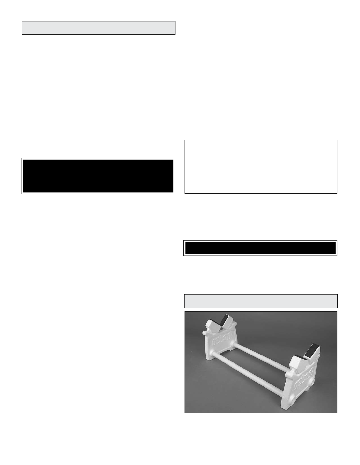
Building Stand
7. If you are not an experienced pilot or have not flown
this type of model before, we recommend that you get the
assistance of an experienced pilot in your R/C club for
your first flights. If you’re not a member of a club, your local
hobby shop has information about clubs in your area whose
membership includes experienced pilots.
A building stand or cradle comes in very handy during the
build. We use the Robart Super Stand II (ROBP1402) for
most of our projects in R&D, and it can be seen in pictures
throughout this manual.
3
Page 4

Radio Equipment
Since the Edge 540 1.60 ARF is a large model capable of
extreme aerobatics, standard servos should not be used to
operate the control surfaces. Servos with a minimum torque
rating of 98 oz-in [7.1kg-cm] are required except for the
throttle servo which may be operated by a standard servo.
The servos shown in this manual that are used for all of the
control surfaces are Futaba® S3305 servos. A minimum of
six high torque servos and one standard servo (used for
throttle when installing a glow or gas engine) are needed to
complete the Edge:
A battery pack with a minimum of 1500mAh capacity should
also be used. When flying large models such as the Edge 540
1.60 ARF, ALWAYS check the battery condition before each
flight. If you are installing a gas engine with an electronic
ignition module, a separate battery pack (the EI pack does
not need to be high capacity) will also be required in addition
to the battery pack used to power the receiver and servos.
o Hobbico HydriMax
(HCAM6321)
A heavy-duty receiver switch and charge jack will also
be needed:
™
4.8V 2000mAh NiMH Flat AA Rx U
o Futaba S3305 Servo High-Torque Standard w/Metal
Gears (FUMT0045)
o Futaba S9001 Servo Aircraft Coreless BB (FUTM0075)
Because of heavy loads on the control surfaces, heavyduty servo arms should be used on all of the control surface
servos. The throttle servo can use the servo arm supplied
with the servo. This manual shows the installation of Great
Planes 1.5” [38mm] aluminum single-sided servo arms. If the
rudder servos will be installed in the aft location, six arms will
be needed. If the rudder servos are installed in the forward
position, only four arms will be needed. See the building
instructions for details on the rudder servo positions.
o Great Planes Large Scale 1.5" Single Side Servo Arm
(GPMM1105)
The following servo extensions and Y-harnesses were
also used to build the Edge 540 1.60 ARF as shown in
the manual:
o Two 36” [914mm] servo extensions for elevator servos
(HCAM2726 for Futaba J-connector)
o Two 36” [914mm] servo extensions for rudder servos
when installed in the optional aft location (HCAM2726 for
Futaba J-connector)
o Two 24” [610mm] servo extensions for aileron servos
(HCAM2721 for Futaba J-connector)
o One 6” [152mm] servo extension for receiver battery pack
(HCAM2701 for Futaba J-connector)
o One 12” [305mm] servo extension for brushless ESC if
applicable (HCAM2711 for Futaba J-connector)
o Futaba Heavy-duty Switch Harness w/Charge Cord
(FUTM4385)
o Ernst Charge Receptacle Futaba J FM (ERNM3001)
If installing a gas engine, an additional switch (standard
size) and charge jack will also be needed:
o Futaba SWH13 Switch Harness & Charge Cord Mini J
(FUTM4370)
If using a radio system that does not support mixing of
the elevator, rudder, and aileron servos, Y-harnesses will
be required:
o Two Hobbico
servos (HCAM2751 for Futaba J-connector)
®
Pro HD Y-Harnesses for rudder and aileron
o One Reversing Y-Harness for elevator servos (EMOM0027
for Futaba J-connector)
Note: The list of servo extensions and Y-harnesses is based
on the equipment we used to set up the Edge as detailed in
the manual. The length or quantity may vary depending on
the actual equipment being used, radio locations, etc.
4
Page 5

Engine Recommendations
The recommended engine size range for the Edge 540 1.60
ARF is 1.6 to 1.8 cu in [26–30cc] two-stroke glow engine, 1.8
to 2.1 cu in [30–34cc] four-stroke glow engine, or 1.9 to 2.6
cu in [32–43cc] gasoline engine. We recommend either the
O.S.® 1.60 FX glow engine (OSMG0661) or the Fuji-Imvac™
BT-43 EI-2 gasoline engine (FJIG0144). The Edge is also
designed to accept a Great Planes 63-62-250kV RimFire™
brushless out-runner motor. All of these power systems will
allow the Edge to perform the 3D maneuvers it was designed
for and installations are covered in this manual.
GLOW ENGINE REQUIREMENTS
Note: The total recommended voltage for the LiPo battery
pack configuration is 33.3V to 44.4V. This can be done in
combinations of battery packs ranging in voltage. Be sure
that the capacity (mAh) of all packs used are the same value
(example: do not mix 3200mAh packs with 5000mAh packs).
The battery pack combination should be connected together
using the recommended series adapter. The actual quantity
of adapters needed depends on the number of packs being
used. Each adapter will connect two packs together in series.
If three 11.1V packs are joined to make 33.3V, two series
adapters will be needed (one series adapter will join two
11.1V packs together to make 22.2V, the second adapter
will combine that 22.2V with the remaining 11.1V pack for a
total of 33.3V). If four 11.1V packs are combined for a total
of 44.4V, then three series adapters will be needed. Other
voltage combinations may require more or less adapters.
The only required accessory needed to install a glow engine
is a Pitts style muffler. If using the O.S. 1.60 FX glow engine,
the order number for a Pitts style muffler is Bisson O.S. 1.60
FX Pitts Muffler (BISG4116).
BRUSHLESS MOTOR REQUIREMENTS
If installing the Great Planes 63-62-250kV RimFire out-runner
brushless motor (GPMG4795), you will also need to purchase:
o Great Planes Brushless Motor Mount Extra Large
(GPMG1265)
o Great Planes SS100 100A Brushless ESC (GPMM1870)
o 9-12 cells (3 or 4 11.1V packs) 3200mAh LiPo Batteries:
Great Planes LiPo 11.1V 3200mAh 20C Discharge w/
Balance (GPMP0623)
o Great Planes Series Deans
(GPMM3143)
®
Ultra Plug® 2 to 1 Adapter
o Great Planes Velcro Hook & Loop 1x6" (2) (GPMQ4480)
o LiPo compatible battery charger such as the Great
Planes PolyCharge4™ DC Only 4 Output LiPo Charger
(GPMM3015)
o Great Planes ElectriFly
(GPMM3160)
The included spinner adapter nut is designed specifically to
fit into the tapered jam nut used on the O.S. 1.60 FX glow
engine. Because of this, an adapter nut must be purchased
to work with the RimFire prop adapter. You can use Tru Turn
Adapter Kit O.S. 1.08 (TRUQ3065) or Dave Brown X-Long
Adapter Nut 3/8-24 (DAVQ6324). Both of these adapter nuts
require a 10-32 spinner bolt that will need to be purchased
separately. The length of the bolt will depend on the adapter
nut being used. We suggest purchasing a 10-32 x 2-3/4”
[70mm] spinner bolt and cutting it to the necessary length.
Another option is to purchase the nut and prop washer
set for the O.S. 1.60 FX engine, O.S. Locknut Set 1.60 FX
(OSMG6688). Using the O.S. prop nut will allow you to
also use the adapter nut included with the kit as well as the
included 5mm prop bolt.
™
Equinox™ LiPo Cell Balancer
The recommended hook and loop material is used to join
the individual battery packs together, securing them onto
the battery tray, and securing the ESC to the ESC tray. One
package of Great Planes hook and loop contains 12” [305mm]
of material. We suggest purchasing at least two packages.
The recommended PolyCharge4 will charge up to four LiPo
packs simultaneously. To do so, an Equinox Cell Balancer is
required for each individual LiPo pack. The PolyCharge4 is
a DC only charger, so a suitable DC power source will also
be required.
GAS ENGINE REQUIREMENTS
The fuel tank included with this kit is suitable for use with
glow fuel. However, if using a gas engine, the fuel tank
must be converted to work with gasoline. This can be
done by purchasing a Sullivan #484 Gasoline/Diesel fuel
tank conversion kit (SULQ2684), two packages of Du-Bro
#813 1/8” [3.2mm] I.D. fuel line barbs (DUBQ0670) and at
least 3’ [914mm] of gasoline compatible fuel tubing (such
as Tygon). Without the fuel line barbs, some types of gascompatible fuel line may slip off the metal fuel tubes. If the
Sullivan conversion kit is not available, the Du-Bro #400 gas
conversion stopper (DUBQ0675) and one package of K&S
1/8” [3.2mm] soft brass tubing (K+SR5127) could also be
used to make the conversion.
Also, the hardware needed to mount a gas engine to the
firewall is not included with the kit. The hardware that is
detailed in the building instructions of this manual for mounting
the Fuji-Imvac BT-43 EI-2 engine includes four 10-32 x 1-1/4”
[32mm] socket head cap screws, four #10 flat washers, four
#10 lock washers (split washers), and four 10-32 blind nuts.
This hardware can be purchased at a hardware store, home
center, or your hobby supplier.
5
Page 6
Propeller
Optional Supplies and Tools
Choose the propeller that is appropriate for the power system
you are using. If installing the Great Planes 63-62-250kV
RimFire out-runner motor, the propeller choice will depend
on the battery voltage being used. A 9-cell (33.3V) pack will
require a 20 x 10 prop (APCQ2200). A 12-cell (44.4V) pack
will require an 18 x 8 prop (APCQ3010). If installing an O.S.
1.60 FX glow engine, we recommend using a 18 x 6W prop
(APCQ1806). If installing the Fuji-Imvac BT-43 EI-2 engine,
we recommend using a 20 x 8 prop (APCQ2080).
ADDITIONAL ITEMS REQUIRED
Adhesives and Building Supplies
Here is a list of optional supplies and tools that will help you
build the Edge 540 1.60 ARF.
o Great Planes 1/4 Sport Pilot Yellow (GPMQ9012)
o Fuel filler valve for glow fuel (GPMQ4160)
o Fuel filler valve for gasoline (GPMQ4161)
o 1/2 oz. [15g] Thick Pro CA- (GPMR6013)
o Stick-on segmented lead weights (GPMQ4485)
o Epoxy brushes (6, GPMR8060)
o Mixing sticks (50, GPMR8055)
o Mixing cups (GPMR8056)
o Builder’s Triangle Set (HCAR0480)
o 36" metal ruler (HCAR0475)
o Pliers with wire cutter (HCAR0630)
o T.A. Emerald Performance Duster can of compressed air
(TAEC1060)
o Rotary tool such as Dremel
o Rotary tool reinforced cut-off wheel (GPMR8200)
o Servo horn drill (HCAR0698)
o CG Machine
™
(GPMR2400)
o #64 Rubber bands (1/4 lb [113g] box, HCAQ2020)
This is the list of Adhesives and Building Supplies that are
required to finish the Edge 540 1.60 ARF.
o Pro 30-minute epoxy (GPMR6047)
o 1/2 oz. [15g] Thin Pro
™
CA (GPMR6001)
o 1/2 oz. [15g] Medium Pro CA+ (GPMR6007)
o Hobbico 60 watt soldering iron (HCAR0776) or Hobby
Heat™ Micro Torch II (HCAR0755)
o Silver solder w/flux (STAR2000)
o Petroleum jelly (Vaseline)
o 3' [900mm] standard silicone fuel tubing (GPMQ4131)
(glow engine only)
o R/C foam rubber (1/4" [6mm] - HCAQ1000)
o Drill bits: 1/16" [1.6mm], 3/32" [2.4mm], 7/64" [2.8mm],
1/8" [3.2mm], 9/64" [3.6mm], 5/32" [4mm], 3/16" [4.8mm],
7/32" [5.6mm], 3/16" [4.8mm], 1/4" [6.4mm]
o Denatured alcohol (for epoxy clean up)
o 8-32 tap and drill set (GPMR8103), glow engine only
o Tap handle (GPMR8120), glow engine only
o #1 Hobby knife (HCAR0105)
o #11 blades (5-pack, HCAR0211)
o Masking tape (TOPR8018)
o T-pins (HCAR5150)
o Great Planes Pro Threadlocker (GPMR6060)
o Dead Center
glow engine only
™
Engine Mount Hole Locator (GPMR8130),
o Panel Line Pen (TOPQ2510)
o 1" [25mm] double-sided foam tape (GPMQ4442)
o 220-grit Sandpaper (GPMR6185)
o 21st Century
®
sealing iron (COVR2700)
o 21st Century iron cover (COVR2702)
o 21st Century trim seal iron (COVR2750)
IMPORTANT BUILDING NOTES
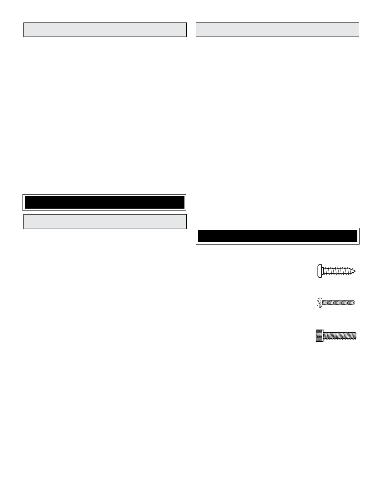
• There are two types of screws used in this kit:
Self-tapping screws are designated
by a number and a length. For example,
#6 x 3/4" [19mm].
Machine screws are designated by a
number, threads per inch, and a length.
For example, 4-40 x 3/4" [19mm].
Socket Head Cap Screws (SHCS) are
designated by a number, threads per
inch, and a length. For example, 4-40 x
3/4" [19mm]
• When you see the term test fit in the instructions, it means
that you should first position the part on the assembly
without using any glue, then slightly modify or custom fit
the part as necessary for the best fit.
• Whenever the term glue is written you should rely upon
your experience to decide what type of glue to use. When
a specific type of adhesive works best for that step, the
instructions will make a recommendation.
• Whenever just epoxy is specified you may use either
30-minute (or 45-minute) epoxy or 6-minute epoxy. When
30-minute epoxy is specified it is highly recommended that
you use only 30-minute (or 45-minute) epoxy, because you
will need the working time and/or the additional strength.
6
Page 7

• Photos and sketches are placed before the step they
refer to. Frequently you can study photos in following steps
to get another view of the same parts.
• The stabilizer and wing incidences and engine thrust
angles have been factory-built into this model. However,
some technically-minded modelers may wish to check
these measurements anyway. To view this information visit
the web site at www.greatplanes.com and click on
“Technical Data.” Due to manufacturing tolerances which
will have little or no effect on the way your model will fly,
please expect slight deviations between your model and
the published values.
• The Edge 540 1.60 ARF is factory-covered with Top Flite
MonoKote® film. Should repairs ever be required, MonoKote
can be patched with additional MonoKote purchased
separately. MonoKote is packaged in six-foot rolls, but
some hobby shops also sell it by the foot. If only a small
piece of MonoKote is needed for a minor patch, perhaps a
fellow modeler would give you some. MonoKote is applied
with a model airplane covering iron, but in an emergency a
regular iron could be used. A roll of MonoKote includes full
instructions for application. Following are the colors used
on this model and order numbers for six foot rolls.
Yellow (TOPQ0203)
White (TOPQ0204)
Missile Red (TOPQ0201)
Metallic Blue (TOPQ0402)
ORDERING REPLACEMENT PARTS
Replacement parts for the Edge 540 1.6 ARF are available
using the order numbers in the Replacement Parts List that
follows. The fastest, most economical service can be provided
by your hobby dealer or mail-order company.
To locate a hobby dealer, visit the Great Planes web site
at www.greatplanes.com. Choose “Where to Buy” at the
bottom of the menu on the left side of the page. Follow the
instructions provided on the page to locate a U.S., Canadian
or International dealer.
®
Parts may also be ordered directly from Hobby Services by
calling (217) 398-0007, or via facsimile at (217) 398-7721,
but full retail prices and shipping and handling charges will
apply. Illinois and Nevada residents will also be charged
sales tax. If ordering via fax, include a Visa® or MasterCard®
number and expiration date for payment.
Mail parts orders and payments by personal check to:
Hobby Services
3002 N. Apollo Drive, Suite 1
Champaign, IL 61822
Be certain to specify the order number exactly as listed in
the Replacement Parts List. Payment by credit card or
personal check only; no C.O.D.
If additional assistance is required for any reason, contact
Product Support by telephone at (217) 398-8970, or by
e-mail at productsupport@greatplanes.com.
REPLACEMENT PARTS LIST
Order Number Description How to Purchase
Missing pieces ....Contact Product Support
Instruction manual Contact Product Support
Full-size plans ........................Not available
Contact your hobby supplier for the following parts:
GPMA3080 ...... Wing Set
GPMA3081 ...... Fuselage
GPMA3082 ...... Tail Set
GPMA3083 ...... Cowl
GPMA3084 ...... Canopy
GPMA3085 ...... Landing Gear
GPMA3086 ...... Wheel Pants
GPMA3087 ...... Decal
GPMA3088 ...... Canopy/Hatch
GPMA3089 ...... Spinner
7
Page 8
KIT INSPECTION
Before starting to build inspect the parts to make sure they are of acceptable quality. If any parts are missing or are not
of acceptable quality, or if you need assistance with assembly, contact Product Support. When reporting defective or
missing parts, use the part names exactly as they are written in the Kit Contents list.
Great Planes Product Support
3002 N. Apollo Drive, Suite 1
Champaign, IL 61822
Telephone: (217) 398-8970, ext. 5
Fax: (217) 398-7721
E-mail: airsupport@greatplanes.com
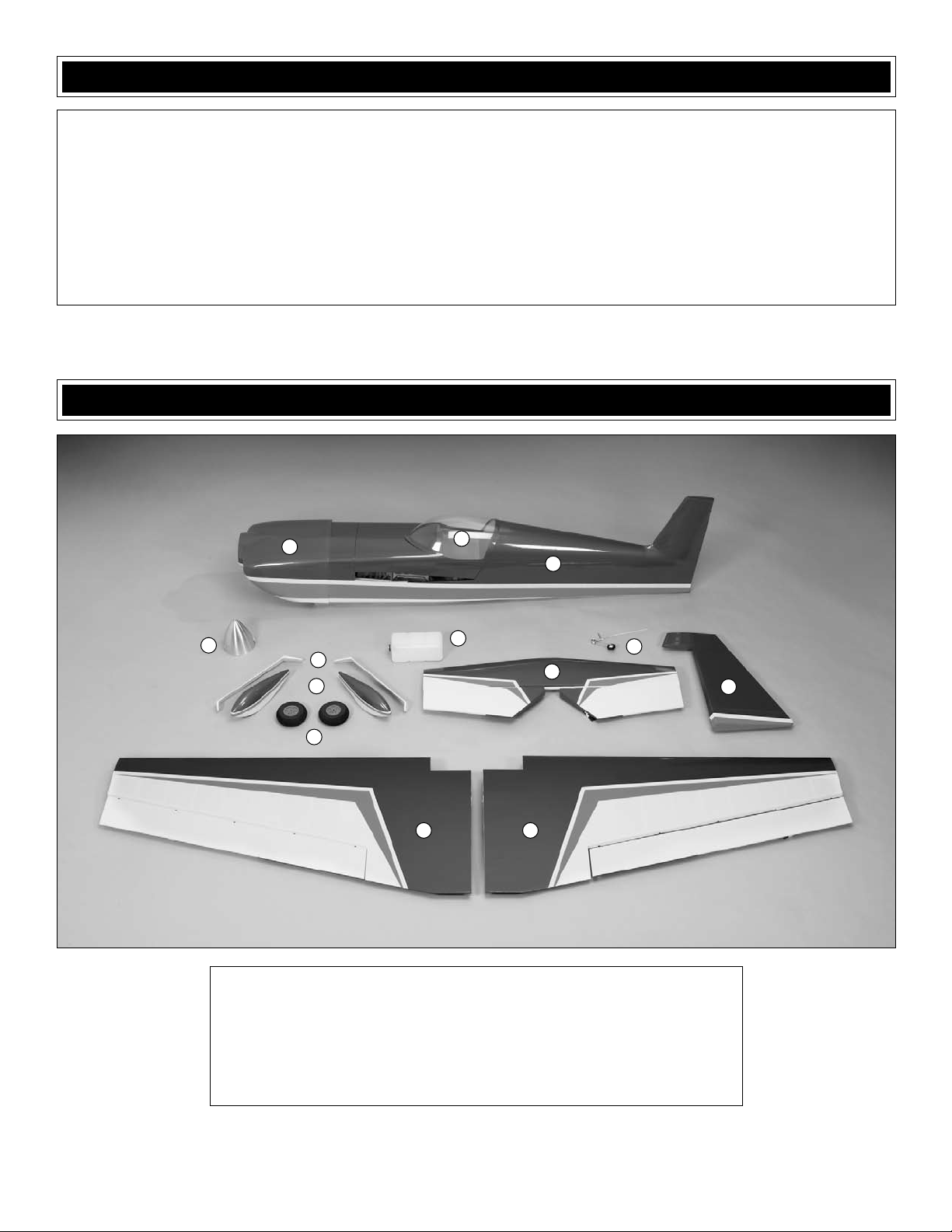
KIT CONTENTS
1
4
1. Cowl
2. Canopy
3. Fuselage
4. Spinner
5. Landing Gear
6. Wheel Pants
7. Main Wheels
2
3
8
5
6
7
12 13
10
9
11
8. Fuel Tank
9. Tailwheel Assembly
10. Horizontal Stabilizer w/Elevators
11. Rudder
12. Left Wing w/Aileron
13. Right Wing w/Aileron
8
Page 9
PREPARATIONS
o 1. If you have not done so already, remove the major parts
of the kit from the box and inspect for damage. If any parts
are damaged or missing, contact Product Support at the
address or telephone number listed in the “Kit Inspection”
section on the prevous page.
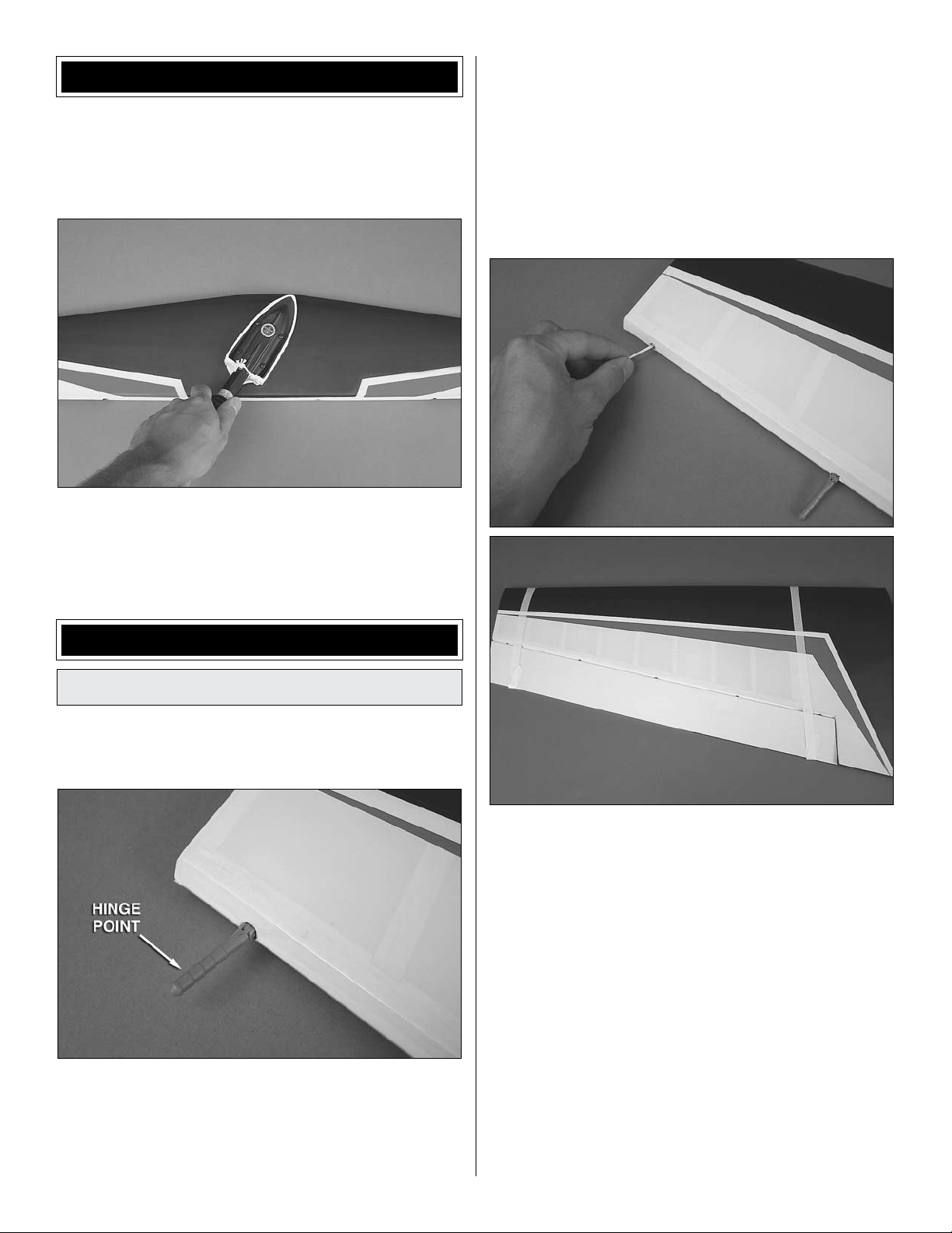
o 2. Carefully remove the tape and separate all the
control surfaces. Use a covering iron with a covering sock
on medium/high heat to tighten the covering if necessary.
Apply pressure over sheeted areas to thoroughly bond the
covering to the wood.
to the wing. The hinge gap between the aileron and wing
should only be wide enough to allow a small line of light
through. Excessive gap will decrease the effectiveness of
the ailerons.
o o 2. Apply a small amount of petroleum jelly or something
similar to the center of each hinge to prevent epoxy from sticking
to the joints and not allowing the hinge to operate smoothly.
READ ALL OF STEP 3 BEFORE PROCEEDING.
ASSEMBLE THE WING
Install the Ailerons
Do the left wing first so your work matches the photos
the first time through. You can do one wing at a time, or
work on them together.
o o 1. Test fit the included hinge points into the pre-drilled
holes in the wing panel and aileron. The hinge points
should seat into the hinge holes all the way to the metal pin
in order to minimize the gap between the aileron and wing.
If necessary, use a hobby knife to enlarge the surface of the
hinge holes until the proper fit is achieved. Test fit the aileron
o o 3. Mix up a batch of 30-minute epoxy. Using a toothpick
or wood scrap, apply epoxy to the inside of each hinge point
hole. The holes are drilled through to the open cavity in the
wing and aileron, so be careful that you do not apply too
much to the walls of the holes as it will simply drip into the
wing. Apply a light coat of epoxy to one end of all the hinges
for one wing panel. Insert the hinge points into the holes in
the wing panel, wiping away excess epoxy with denatured
alcohol as necessary. Be sure the hinges are inserted in the
correct orientation so that the direction of the hinge pin is
inline with trailing edge of the wing. Apply epoxy to the other
ends of the hinges and slide the aileron into position over
the hinges. Use masking tape to hold the aileron in place
while the epoxy cures.
o 4. Repeat these steps for the right wing panel.
99
9
Page 10
Install Aileron Servos and Pushrods
o o 1. Installing the servos in the wing will require the use
of one 24" [610mm] servo extension for each aileron servo.
One Y-harness connector is required and is used to allow the
aileron servos to plug into one slot in your receiver. You may
have a computer radio that allows you to plug the servos
into separate slots and then mix them together through the
radio transmitter. If you choose to mix them together with the
radio rather than a Y-harness, refer to the manual with your
particular model radio system.
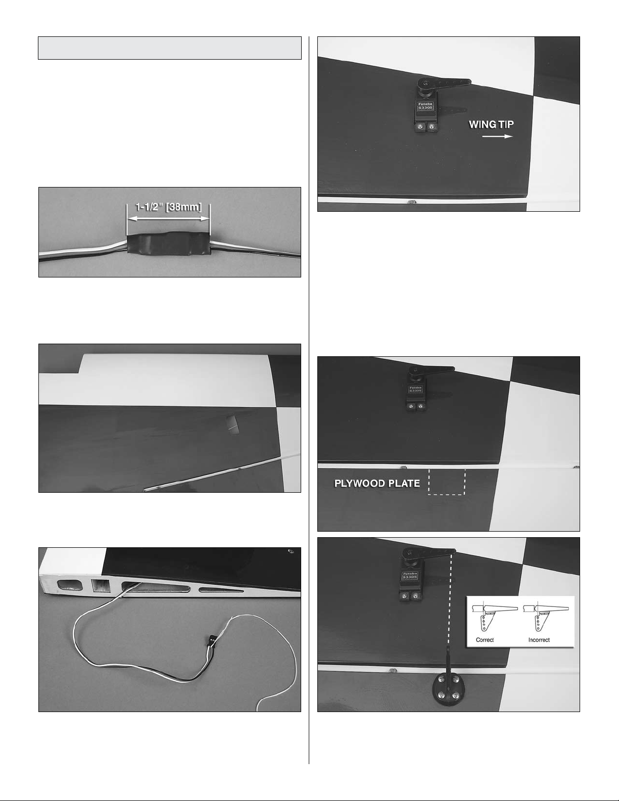
o o 2. Attach the 24" [610mm] servo extension to the
aileron servo and secure it with a piece of the included large
heat shrink tubing. Only 1-1/2" [38mm] of heat shrink tubing
is required for each connector.
o o 5. Temporarily position the aileron servo into the servo
bay. Drill a 1/16" [1.6mm] hole through the four mounting
holes of the servo, drilling through the plywood mounting
plate in the wing. Install and remove a servo mounting screw
into each of the four holes. Apply a drop of thin CA into the
holes to harden the wood. After the glue has cured, install
the servo into the opening using the hardware that came
with your servo. Center the servo with your radio system and
install a servo arm as shown.
o o 3. Cut the covering 1/8" [3mm] inside the opening in the
underside of the wing for the aileron servo. Use a trim iron to
seal the covering to the inner edges of the opening.
The next three images are used for steps 6 and 7.
o o 4. Tie the string from inside the opening for the aileron
servo to the end of the servo extension. Remove the tape
holding the other end of the string to the wing root rib and
pull the servo wire and extension through the wing.
o o 6. The aileron has a plywood plate for mounting the control
horn. You can see the outline of it underneath the covering by
looking at the aileron at a shallow angle. If you cannot see
it, the plate is approximately 1-5/8" [41mm] wide and will be
10
Page 11
inline with the servo arm. Use a T-pin to lightly puncture the
covering to be sure you are over the plywood plate.
o o 7. Place a heavy-duty nylon control horn on the
aileron, positioning it as shown in the sketch inline with the
second outer hole of the servo arm. Mark the location for the
screw holes. Drill through the marks you made with a 3/32"
[2.4mm] drill bit (Be sure you are drilling into the plywood plate
mounted in the bottom of the aileron. Drill through the plate
only. Do not drill all the way through the aileron!). Using
a #4 x 1/2" [13mm] sheet metal screw (there are different
length #4 sheet metal screws included with the model, so
be sure that you are using the correct length screw for this
step), install and then remove a screw into each of the holes.
Harden the holes with thin CA. Install the control horn with
four #4 x 1/2" [13mm] sheet metal screws.
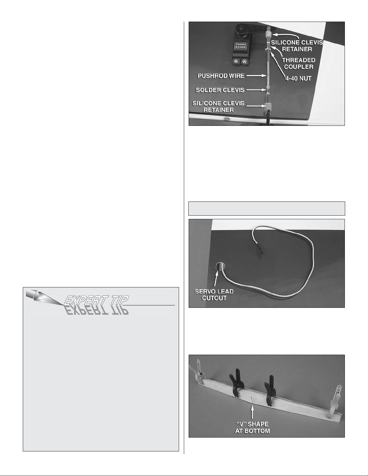
o o 8. Locate a .095" x 6" [2.4mm x 152mm] pushrod wire
threaded on one end. Screw a 4-40 nut, a silicone clevis
retainer and a threaded metal clevis onto the threaded end of
the wire 20 turns. Tighten the nut against the clevis and then
install the clevis on the outer hole of the aileron control horn.
o o 9. Be sure the aileron servo is centered and the servo
arm is parallel to the hinge line. Install a metal solder clevis
onto the second outer hole in the servo arm. Center the
servo arm parallel with the aileron hinge line and center the
aileron. Using the solder clevis as a guide, mark where to cut
the pushrod wire. Remove the pushrod and clevis from the
control horn and the solder clevis from the servo arm. Install
another silicone clevis retainer onto the wire and solder the
clevis to the pushrod using the “Expert Tip” that follows.
o o 10. Install the pushrod and clevises to the second
outer hole in the servo arm and the outer hole in the control
horn. Adjust the linkage until the aileron and the servo arm
are both centered. Then tighten the nut against the clevis
with threadlocking compound. Slide the two silicone clevis
retainers to the end of each clevis.
o 11. Repeat these steps for the right wing panel.
Join the Wing Panels
HOW TO SOLDER THE CLEVIS TO THE PUSHROD
1. Where the pushrod will make contact with the solder
clevis, roughen the wire with 220-grit sandpaper.
2. Use denatured alcohol to remove any oil residue from
the pushrod wire. Note: Soldering should be done with
silver solder, not an electrical solder.
3. Apply a couple of drops of flux to the wire. Slide the solder
clevis onto the wire. Using a small torch or soldering iron
heat the wire, allowing the heated wire to heat the solder
clevis. Apply a small amount of solder to the joint. When
the wire and the clevis are hot enough the solder will flow
into the joint. Avoid using too much solder causing solder
to flow out of the joint and clump. Use just enough solder to
make a good joint. Allow the wire and clevis to cool.
4. Put a couple of drops of oil onto a rag and wipe the
joint. This will prevent rust from forming on the joint.
o 1. Trim the covering from the servo lead cutouts in the
bottom of the wing panels near the root ribs. Feed the aileron
servo leads through the cutouts. Taping the leads to the top
of the wing will keep them out of the way when joining the
wing panels.
o 2. Locate the two aluminum wing joiner pieces and the
wood wing joiner piece. Use 220 grit sandpaper to thoroughly
11
Page 12
roughen both sides of each aluminum wing joiner piece and
remove the sanding dust from the pieces. Glue the three pieces
together using 30-minute epoxy with the two aluminum pieces
against the flat side of the wood piece. Note that the joiner
has a slight “V” shape that will give the wing a small amount
of dihedral when assembled. The point of the “V” shape is
the bottom of the joiner. Wipe away any excess epoxy with
a cloth dampened with denatured alcohol and use clamps to
hold the pieces together while the epoxy cures. Be sure that
the joiner pieces are glued so the edges are flush with each
other. Mark a centerline on the assembled wing joiner.
Read all of step 3 and dry fit the parts together to ensure
a proper fit before gluing. Sand the wing joiner or root
ribs if necessary to achieve the correct fit. The root ribs
should join together tightly with no gaps.
o 3. Use a mixing stick or something similar to coat the
inside of the wing joiner pockets of both wing panels with
30-minute epoxy. Thoroughly coat one half of the wing joiner
with 30-minute epoxy and insert it into the joiner pocket of
one wing panel with the bottom of the “V” shape pointing to
the underside of the wing and the aluminum pieces toward
the LE of the wing. Coat the root ribs of both wing panels and
the protruding end of the wing joiner with epoxy. Slide the
wing panels together and use tape to hold them tight while
the epoxy cures. A small clamp can be used to align the
trailing edge while the epoxy cures. Wipe away any excess
epoxy with denatured alcohol.
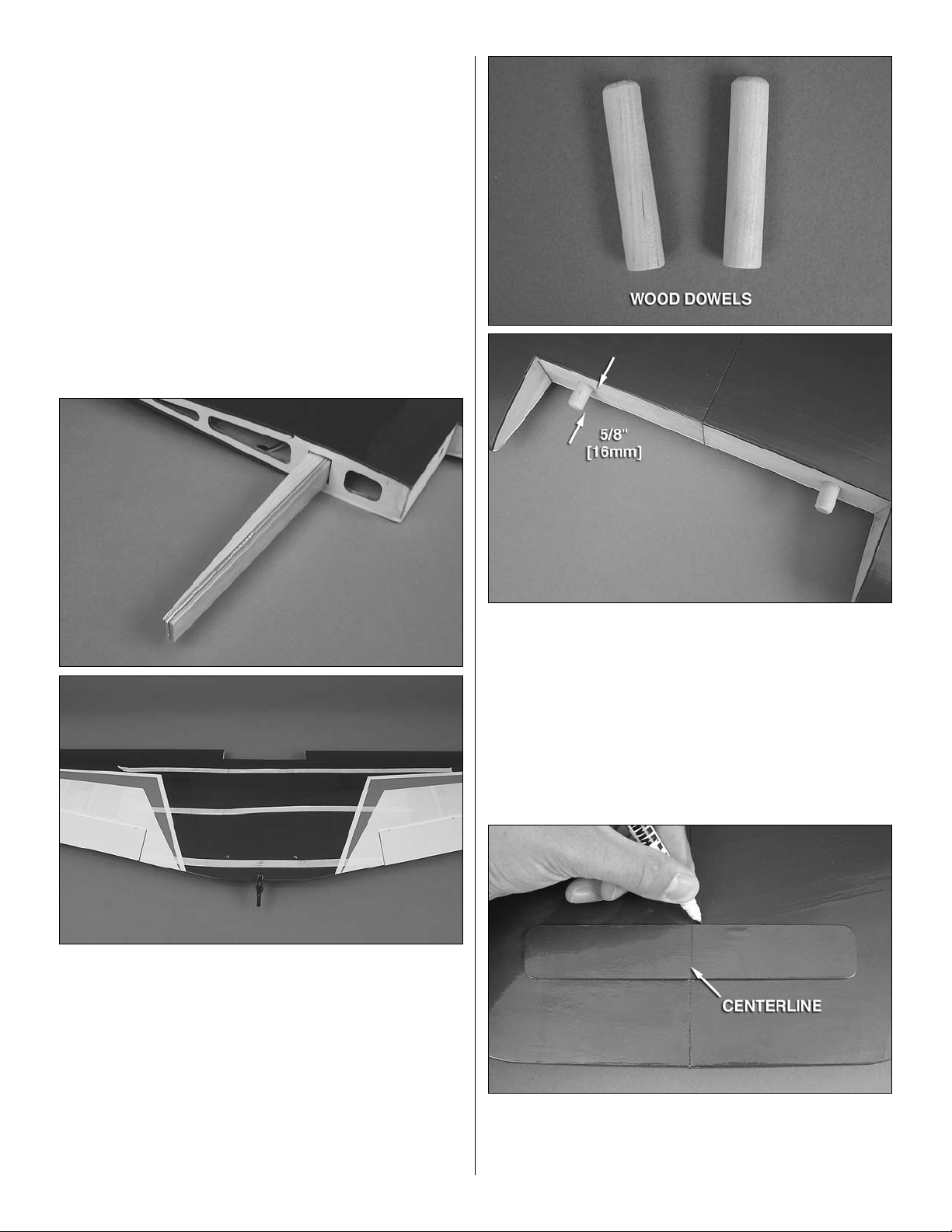
o 4. Bevel the ends of the 3/8" x 2" [10x51mm] wing dowels.
Use epoxy to glue the wing dowels in place. Position the dowels
so that 5/8" [16mm] protrudes beyond the front of wing.
o 5. Draw a center line onto the plywood wing bolt plate as
shown. Position the wing bolt plate over the wing bolt holes
on the underside of the wing and use a felt-tip pen to trace
around it.
12
Page 13
ASSEMBLE THE TAIL SECTION
AND LANDING GEAR
Install Stabilizer, Elevators, and Rudder
o 1. Just as you did with the ailerons, prepare the hinge
point holes in the stabilizer and elevators by test fitting the
hinges and enlarging the holes as necessary. Do not glue
the hinges until instructed to do so.
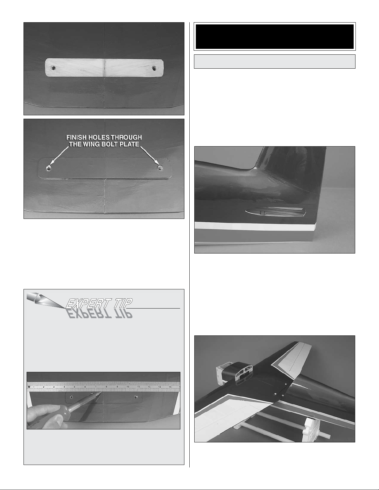
o 6. Use a sharp #11 hobby knife or use the following Expert
Tip to cut the covering 1/16" [1.6mm] inside of the lines you
marked. Use care to cut only in the covering and not into
the wood. Use alcohol to wipe away the lines. Glue the wing
bolt plate in position. Continue the wing bolt holes through
the plate using a 1/4" [6mm] drill bit. Clamp a piece of scrap
wood against the wing bolt plate to reduce tear out when
drilling the holes.
HOW TO CUT COVERING FROM BALSA
Use a soldering iron to cut the covering from the area
beneath the wing bolt plate. The tip of the soldering iron
doesn’t have to be sharp, but a fine tip does work best.
Allow the iron to heat fully.
o 2. Locate the stabilizer slots near the aft end of the
fuselage and trim away the covering.
Use a straightedge to guide the soldering iron at a rate
that will just melt the covering and not burn into the wood.
The hotter the soldering iron, the faster it must travel to
melt a fine cut. Peel off the covering.
o 3. Temporarily install the wing onto the fuselage using two
1/4-20 nylon wing bolts. The wing dowels will fit into receiving
holes in the former behind the leading edge of the wing.
13
Page 14
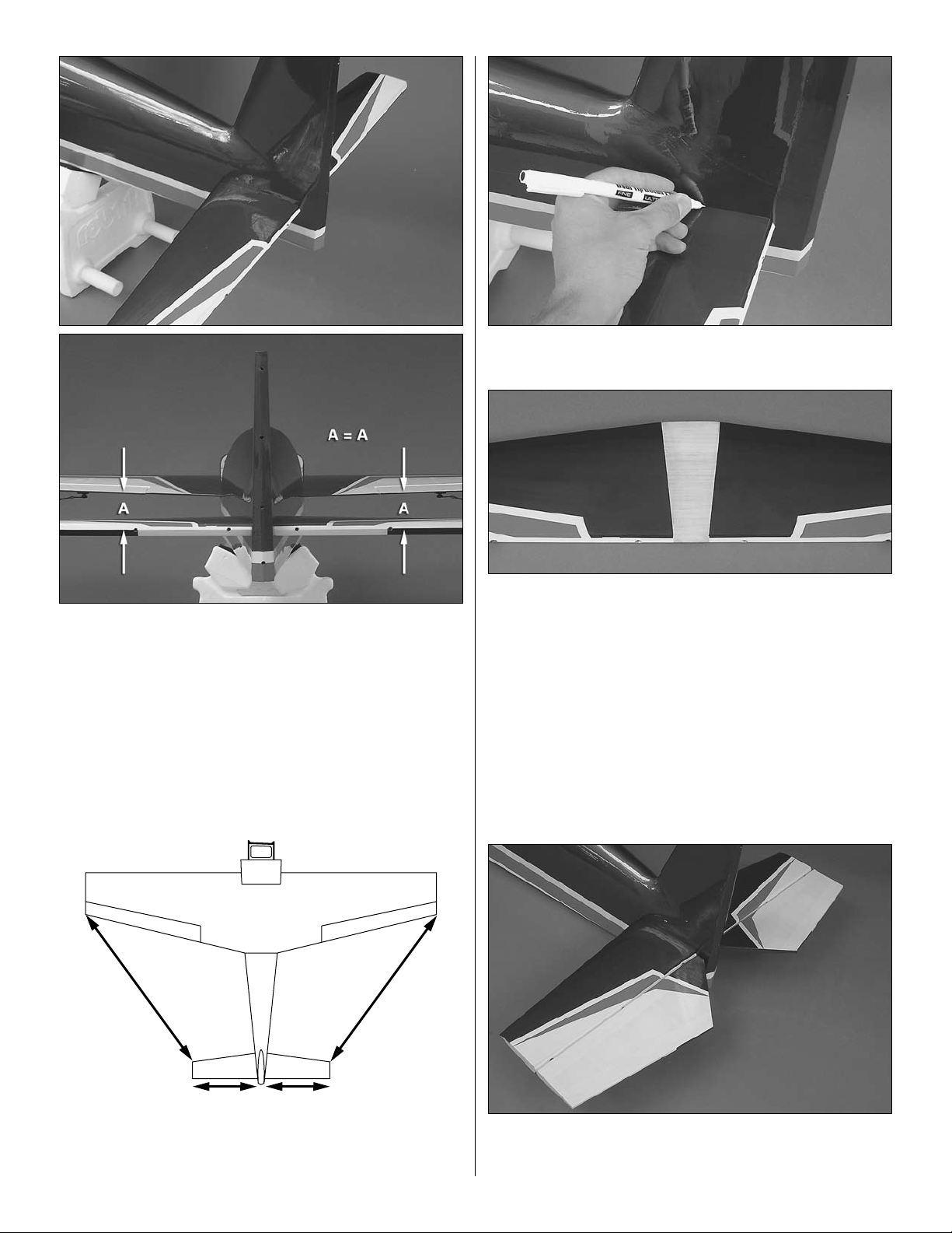
o 4. Test fit the stabilizer in the fuselage. Center the stab left
AA
BB
A = A
B = B
and right in the fuselage. Stand back 15-20ft [5-6m] and check
to be sure the stab is parallel to the wing. If necessary, adjust
the stab saddle as needed until the stab and wing are parallel.
o 6. Use a felt tip marker to mark the outline of the fuselage
onto the top and bottom of the stab.
o 7. Remove the stab from the fuse and cut the covering just
inside the lines you drew. If using a hobby knife to remove
the covering, use care to cut only in the covering and not
into the wood.
o 8. Use 30-minute epoxy to glue the stab into the fuselage.
For the most strength, apply epoxy to both sides of the stab
and inside the fuse where the stab fits. Slide the stab into
position. Confirm that the stab is centered and parallel with
the wing as was done in steps 4 and 5. Wipe away any excess
epoxy with a paper towel and denatured alcohol. Do not
disturb the model until the epoxy has fully hardened. With the
stab secure, you can now remove the wing from the plane.
o 5. Measure the distance from the tip of each wing to the
tip of the stab. Adjust the stab until the distance from the tip
of the stab to the tip of the wing is equal on both sides.
o 9. As you did with the ailerons, use a toothpick or wood
scrap to apply 30-minute epoxy to the inside of each elevator
and stab hinge point hole. Apply a light coat of epoxy to one
14
Page 15
end of all the hinges for the elevators along with a small
amount of petroleum jelly at the center of each hinge. Insert
the hinge points into the holes, wiping away excess epoxy
with denatured alcohol as necessary. Be sure the hinges
are inserted in the correct orientation. Apply epoxy to the
other ends of the hinges and slide the elevators into place.
Use masking tape to hold the elevators in position while the
epoxy cures.
o 10. Attach the rudder in the same manner.
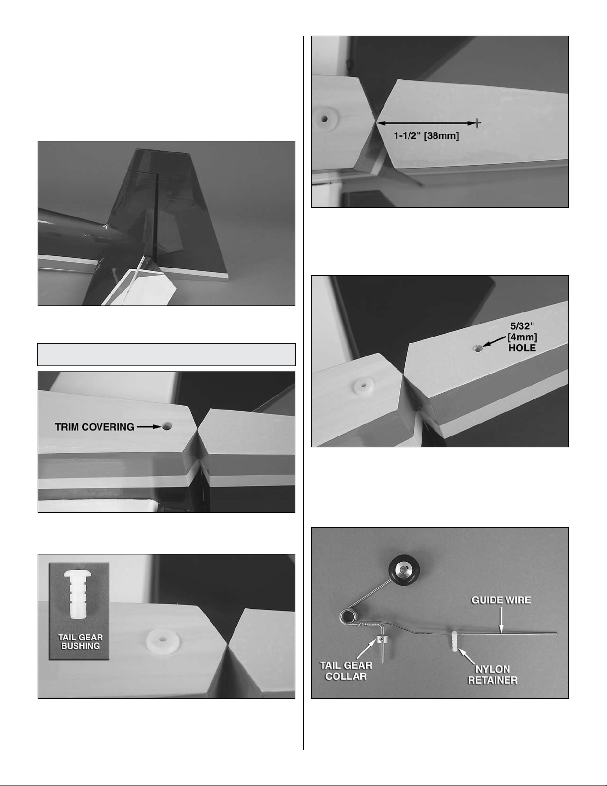
o 3. Measure 1-1/2" [38mm] back from the LE bevel of the
rudder and make a mark on the underside center of the rudder.
Install the Tail Gear Assembly
o 1. Trim the covering from the fuselage for the tail
gear bushing.
o 4. Use a 5/32" [4mm] drill bit to make a 1/2" [13mm] deep
hole at the mark. To improve accuracy, drill a smaller pilot
hole at your mark first.
o 2. Apply CA or epoxy to the outside of the bushing and
insert the bushing into the hole by gently tapping it into place
until fully seated. Be sure not to get glue into the hole in
the bushing.
o 5. Slide the tail gear collar and nylon retainer onto the
tail gear assembly as shown. If necessary, use a 1/16"
[1.6mm] drill bit to enlarge the hole in the retainer for the tail
gear guide wire.
15
Page 16
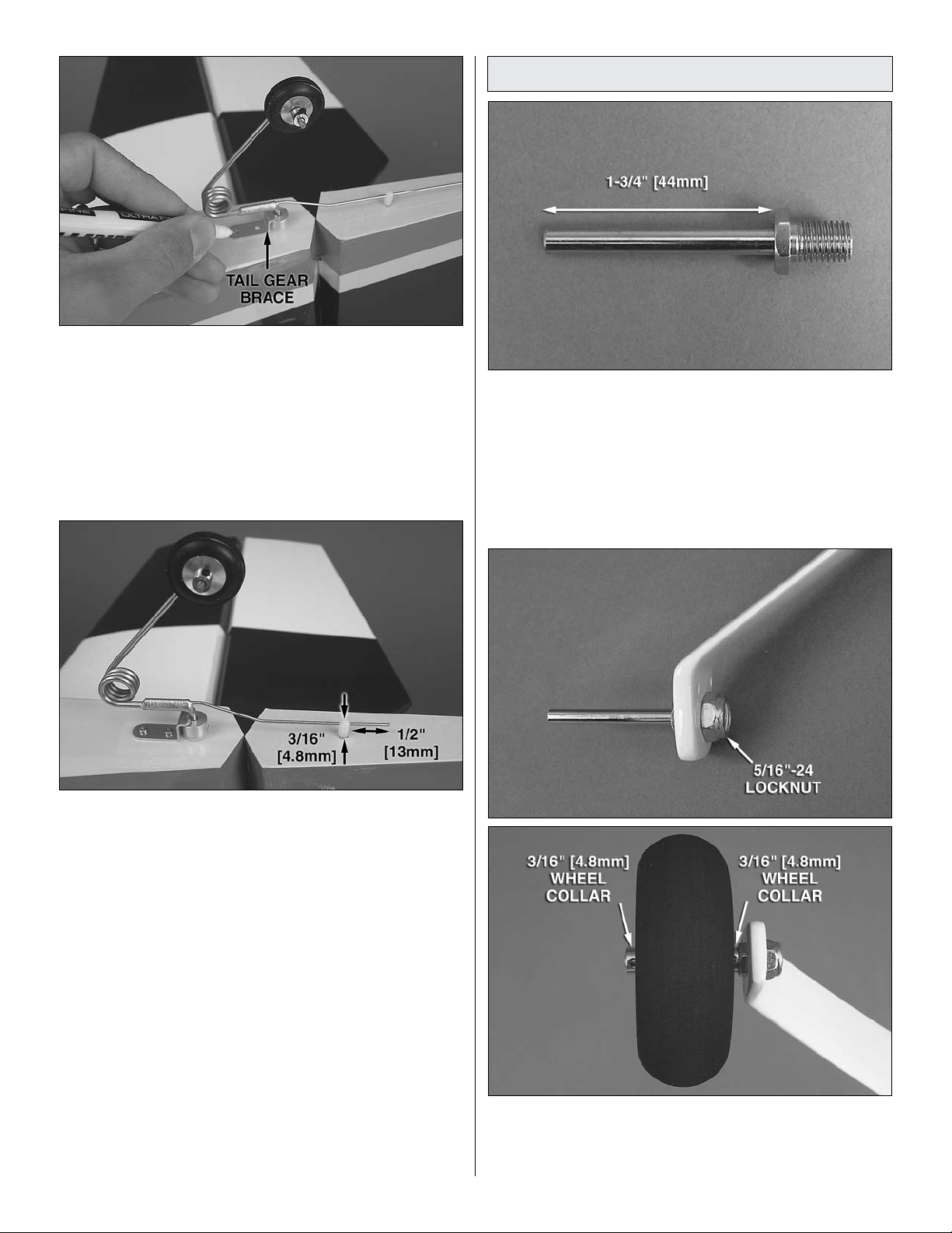
o 6. Temporarily insert the tail gear assembly into the tail gear
bushing and the nylon retainer into the hole you drilled in the
rudder. Center the tail gear bracket onto the fuselage over the
tail gear collar and mark the location of the mounting holes.
o 7. Drill 1/16" [1.6mm] holes at the marks you made. Thread
a 2x8mm self-tapping screw into each hole and back it out.
Apply a couple drops of thin CA glue to each hole and allow
it to harden.
Assemble and Install the Main Gear
o 1. Use a rotary tool with a cutoff wheel or a hacksaw to cut
the two 3/16" x 2" [4.8mm x 51mm] bolt-on axles to 1-3/4"
[44mm] long.
o 8. Apply CA or epoxy to the nylon retainer and reinstall the
tail gear assembly into the bushing and rudder. Do not glue
the nylon retainer to the guide wire. The wire must slide freely
through the hole in the retainer. Gently tap the retainer in
place until approximately 3/16" [4.8mm] protrudes below the
bottom of the rudder. Attach the tail gear bracket using two 2
x 8mm self-tapping screws. Thread the 3mm set screw into
the tail gear collar with a drop of threadlocking compound.
Cut off the excess guide wire 1/2" [13mm] behind the nylon
retainer.
o 9. Confirm that the tail wheel rotates freely. Oil the axle and
adjust the position of the 3mm wheel collar if necessary.
o 2. Attach the axles to the main landing gear legs with two
5/16"-24 locknuts. Slide a 3/16" [4.8mm] wheel collar onto
each axle followed by a 3-1/2" [89mm] wheel and another
3/16" [4.8mm] wheel collar.
16
Page 17
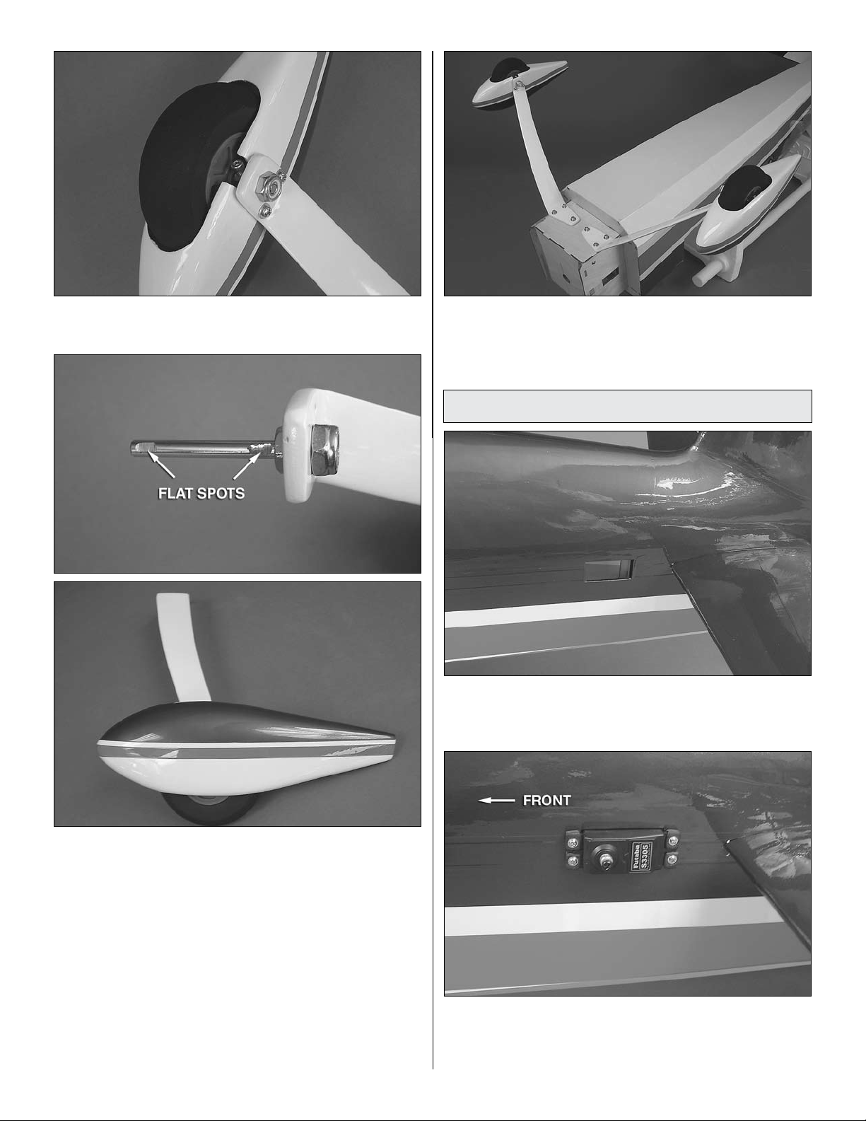
o 3. Temporarily install the wheel pants using four 4-40 x 1/2"
[13mm] machine screws and four #4 flat washers.
o 5. Attach the landing gear to the fuselage using six
6-32 x 1" [25mm] SHCS, six #6 flat washers, six #6 lock
washers, and threadlocking compound.
Install Elevator Servos and Pushrods
o 1. Trim the covering from the elevator servo bays leaving
1/8" [3mm] around the opening. Use a trim iron to seal down
the covering around the edges of the servo bays.
o 4. Position the wheels in the center of the wheel pants,
slide the wheel collars against the wheel hubs, and mark the
location of the screw holes in the wheel collars onto the axles.
Remove the wheel pants from the gear and the wheels and
collars from the axles and grind flat spots at your marks on
the axles for the wheel collar screws using either a file or a
rotary tool. Reinstall the wheels and collars onto the axles and
secure the pants to the gear using four 4-40 x 1/2" [13mm]
machine screws, four #4 flat washers, four #4 lock washers,
and threadlocking compound. Use four 6-32 x 1/4" [6mm]
SHCS and threadlocking compound to secure the wheel
collars to the axles, being sure that you tighten the screws
against the flat spots on the axles. The wheels should rotate
freely between the wheel collars. Oil the axles if necessary.
o 2. Attach a 36" [914mm] servo extension to each elevator
servo. Secure the servo extensions with the included
heat-shrink tubing. Feed the servo extensions through the
fuselage and install the servos into the servo bays with the
17
Page 18

splines facing forward using the mounting hardware included
with the servos. Be sure to harden the servo mounting screw
holes with thin CA.
o 3. Attach a servo arm to each elevator servo with the arm
pointing downward.
The following sections contain detailed instructions
for mounting an O.S. 1.60 FX two-stroke glow engine,
Fuji-Imvac BT-43 EI-2 gasoline engine, and the Great
Planes RimFire 63-62-250kV outrunner brushless
motor. Each specific installation only contains
information relevant to that particular power system
so you can skip directly to the section that matches
your choice of power systems.
GLOW ENGINE INSTALLATION
Mount the Engine
The installation of a brand of glow engine other than the
O.S. 1.60 FX should be similar to the procedure listed
below for the O.S. model. A mounting template is provided
on page 53 of this manual for installing the included Great
Planes 1.20-1.80 nylon adjustable engine mount.
o 4. Just as you did with the ailerons, begin assembly of the
elevator pushrods using two .095" x 12" [2.4mm x 305mm]
pushrod wires threaded on one end, two 4-40 clevises, and
two 4-40 nuts. Attach the clevis of each pushrod to the servo
arms and use the pushrod as a guide to position the control
horns onto the underside of the elevators. Secure the control
horns to the elevators with eight #4 x 5/8" [16mm] sheet
metal screws, being sure that you are drilling the screw holes
through the plywood plates in the elevators. Do not drill all
the way through the elevators! Center the elevators and
use a solder clevis to mark where to cut the pushrod wires.
Cut the wires, solder the clevises to the pushrods, and attach
the pushrods to the elevators, securing the clevises with
silicone clevis retainers.
Note: The Edge 540 1.60 ARF is set up for either forward
(pull-pull system) or aft (pushrod system) rudder servo
positions in order to offset ballast that may be required to
balance the airplane. The rudder servos will be installed
after the power system is put in place. After the installation
of the power system, the current C.G. of the plane can be
checked which will determine the optimum location of the
rudder servos.
o 1. Cut the template out on page 53 for mounting the O.S.
1.60 FX glow engine. Use tape or spray adhesive to hold
the glow engine mount template to the firewall. Align the
vertical and horizontal lines on the template with the lines on
the firewall.
o 2. Use a large T-pin or a wire sharpened on the end to
transfer each bolt hole mark on the template onto the firewall.
18
18
Page 19

o 3. Use a 7/32" [5.6mm] bit to drill holes at the four marks
you made on the firewall. To reduce tear-out, make pilot
holes with a smaller bit first, then finish the holes with the
7/32" [5.6mm] bit. Insert a 8-32 blind nut into the back of
each hole. Use a 8-32 x 1-1/4" [32mm] SHCS and a few #8
flat washers to draw the blind nuts tight against the back of
the firewall.
o 5. Fit the engine onto the mount and slide the engine mount
halves together against the engine crankcase. Remove the
engine and tighten the engine mount screws. Reposition the
engine onto the mount so that the front of the drive washer is
6-3/4" [171mm] from the firewall.
o 6. Use a Great Planes Dead Center
small drill bit to mark the engine mounting holes onto the
engine mount.
™
Hole Locator or a
o 4. Loosely install the 1.20 to 1.80 nylon engine mount
to the firewall using four 8-32 x 1-1/4" [32mm] SHCS, four
#8 flat washers, four #8 lock washers and threadlocking
compound. The engine mount should be oriented so that the
engine head will be on the right side of the plane.
o 7. Drill 9/64" [3.6mm] holes at the marks you made and
thread the holes using a 8-32 tap and handle. Install the
engine onto the mount using four 8-32 x 1" [25mm] SHCS,
four #8 flat washers and four #8 lock washers.
19
Page 20

o 8. Attach a Pitts-style muffler to the engine using
TOP OF TANK
VENT
FILL AND CARB LINES
threadlocking compound.
Install the Fuel Tank (Glow)
installing a fueler valve or are omitting the fill line, install only
two tubes into the stopper (one short tube and one long tube)
leaving the third hole in the stopper sealed.
o 4. Install the metal plates on the front and back of the
stopper and loosely thread the 3mm x 25mm phillips screw
through the plates. Attach a silicone fuel line 6" [152mm] in
length to each of the two short tubes in the stopper. The long
tube (vent line) should be bent upward as shown (be careful
not to kink the tube while bending it). Install the included fuel
clunks onto the fuel lines.
o 1. Locate the fuel tank. The hardware needed for the fuel
tank assembly is inside of the tank. Remove the stopper and
shake out the contents.
o 2. The fuel system for the Edge 540 1.60 ARF utilizes a
three line system. There is a fill line, carb line, and vent
line (to muffler). The fill line will allow fueling and defueling
without removing the cowl. The fill line is optional and may be
omitted if desired, or an optional Great Planes Easy Fueler
Valve (not included) can be installed.
o 3. Use a hobby knife to open up the sealed third hole in
the rubber stopper for the fill line. Slide the three aluminum
fuel tubes into the rubber stopper so that the tubes extend
beyond the front of the stopper by 1/2" [13mm]. If you are
o 5. Insert the stopper into the tank and check the length of
the carb line and fill line. The clunks should almost reach the
back of the tank when the stopper is in place but be able to
move around freely inside the tank. Adjust the length of the
fuel line until the proper length has been reached. The vent
line should almost reach the top of the tank. Once you are
satisfied with the fit, secure the stopper using the phillips
screw in the stopper assembly. Be careful not to over-tighten
as the fuel tank could split.
20
Page 21

o 6. Insert the fuel tank into the fuselage as shown with
the neck of the tank pushed as far forward in the hole in the
fuselage as it will fit. The vent line should be at the top of the
tank. Secure the fuel tank inside the fuse by hooking two
of the included rubber bands around the rubber band tabs
as shown. Attach a length of fuel tubing approximately 9"
[229mm] long to each of the fuel tank tubes.
Install the Throttle Servo (Glow)
o 1. Attach the throttle servo to the firewall box as shown
using the hardware included with the servo. Be sure to use
thin CA in the servo mounting holes.
o 2. Cut three arms from a four arm servo arm and attach it
to the throttle servo pointing down.
o 7. Cut the fuel tubing on the vent and carb lines to the
necessary length and connect them to the engine. Locate
the three pieces that make the optional fuel line mount. This
part is used to hold the fill line at the bottom of the firewall (if
an Easy Fueler valve is being used or some similar system,
this part can be omitted). Glue the pieces together as shown.
Use epoxy to fuel proof the part. Sand the bottom center
of the firewall where the part will be glued with 220 grit
sandpaper. Glue the piece in place and clip the fill line into
one of the slots in the fuel line mount. The fill line can now be
cut to length. A fuel line plug is provided for the fill line.
o 3. Install a brass screw-lock pushrod connector using
a nylon retainer to the outer hole in the throttle servo arm.
Loosely install a 4-40 x 1/8" [3mm] SHCS into the brass
screw-lock connector. Install a nylon clevis and silicone clevis
retainer 20 complete turns onto the .074" x 12" [1.9mm x
305mm] pushrod and bend the pushrod to fit from the throttle
servo arm to the carburetor arm. When bending the rod, be
sure there is clearance between the engine/muffler and
the pushrod through the entire travel of the throttle servo.
Metal to metal contact will cause radio interference. When
satisfied, fit the pushrod through the screw-lock connector
and connect the clevis to the carburetor arm. Slide the
silicone clevis retainer to the end of the clevis and make
any necessary adjustments to the pushrod length. Use your
radio system to test the operation of the throttle servo. With
all fine adjustments made, finish tightening the 4-40 x 1/8"
[3mm] SHCS against the pushrod.
21
Page 22

GAS ENGINE INSTALLATION
Mount the Engine
A template is provided on page 53 for mounting the Fuji-Imvac
BT-43 EI-2 engine and pictures taken show the installation of
this model gas engine. If another model engine is used, the
engine manufacturer may provide a mounting template to
use on the firewall. The gas engine installation will be similar
for most model engines.
Because of the possibility of ignition engines creating
radio noise, we use a plastic pushrod for the throttle
servo installation. This isolates the engine and any
radio noise from the servos. This is an IMPORTANT
selection, and we cannot recommend strongly
enough that you DO NOT change this pushrod to a
metal pushrod. All radio equipment–including throttle
servo, receiver battery, receiver on/off switch, servo
leads–should be mounted at least 10" [254mm] away
from anything related to the ignition/gasoline engine.
Any material used between the engine and the radio
equipment is STRONGLY recommended to be plastic,
nylon, or otherwise non-metallic and nonconductive
to minimize ignition noise transmission.
o 1. Cut the template out on page 53 for mounting the Fuji-
Imvac BT-43 EI-2 engine. Use tape or spray adhesive to hold
the template to the firewall. Align the vertical and horizontal
lines on the template with the lines on the firewall.
o 3. Measure the outer diameter of the boss on the blind nuts
you will use to mount the engine (gasoline engine mounting
hardware is not included). The 10-32 blind nuts we use will
require a 1/4" [6.3mm] bit. Use the appropriate bit for your
hardware to drill holes at the four marks you made on the
firewall. To reduce tear-out, make pilot holes with a smaller
bit first, then finish the holes with the correct diameter bit.
Insert a 10-32 blind nut into the back of each hole. Use a
10-32 x 1-1/4" [32mm] SHCS and a few #10 flat washers to
draw the blind nuts tight against the back of the firewall.
o 2. Use a large T-pin or a wire sharpened on the end to
transfer each bolt hole mark on the template into the firewall.
22
Page 23

o 4. Attach the included ball stud to the throttle arm on
the carburetor with a 2-56 nylon lock nut. Mount the engine
inverted using four 10-32 x 1-1/4" [32mm] SHCS (not included),
four #10 flat washers (not included), four #10 lock washers
(not included), and threadlocking compound. The distance
from the firewall to the front of the drive washer is 6-3/4"
[171mm] when installing the Fuji-Imvac BT-43 EI-2 engine.
This distance may vary slightly with other engine models. If
installing another model engine, effort should be made to
maintain a similar drive washer distance to the firewall.
Install the Fuel Tank (Gas)
The fuel line and stopper included with the Edge 540 1.60
ARF is NOT gasoline safe. Gasoline will degrade the rubber
stopper and silicone fuel tubing supplied. You will need to
purchase a gasoline safe stopper and gasoline safe tubing
to use for the fuel system on this model. The Sullivan #484
Gasoline/Diesel fuel tank conversion kit (SULQ2684)
works well for this.
o 1. Remove the stopper from the included fuel tank and
replace it with a gas safe stopper as mentioned above.
o A. Cut one of the two brass tubes included with the
Sullivan conversion kit in half (approximately 1-3/4" [45mm]
pieces). Prepare the tubes for solder by scuffing up the
ends with sandpaper and cleaning them with alcohol.
o B. Assemble the stopper by inserting the tubes through
the large stopper plate, stopper, and then the small
stopper plate. Join the plates and stopper together using
the screw that came with the conversion kit.
o 2. Assemble the stopper using Du-Bro #813 1/8" [3.2mm]
I.D. fuel line barbs and 1/8" [3.2mm] brass tubing as shown.
Solder the barbs to the brass tubing but be careful not to
overheat the assembly as it could cause damage to the
rubber stopper.
o C. Solder a Du-Bro fuel line barb onto one end of each
of the three tubes (be sure that the barbs are positioned in
the correct direction on the tubes so that they will secure
the fuel tubing when fitted in place). Slide the barbs in
place and apply a small amount of solder to the joints
between the barbs and the tubes. Solder will wick into the
joints securing them in place. Be careful not to use too
much solder as it could obstruct fuel flow inside the tubes.
Note: The item used in the picture above to hold the tubes
is the X-Acto Extra Hands Double Clip (XACR4214).
o D. Solder a barb onto the other end of each short
brass tube.
23
Page 24

o 3. Carefully bend the tubes that exit the stopper as shown.
TOP OF TANK
VENT
FILL AND CARB LINES
Be sure that the lines do not have kinks at the bends. Attach
a gasoline compatible fuel line such as Tygon 6" [152mm] in
length to each of the two short tubes in the stopper. The long
tube (vent line) should be bent upward. Install the included
fuel clunks onto the fuel lines.
o 4. Insert the stopper into the tank and check the length of
the carb line and fill lines. The clunks should almost reach
the back of the tank when the stopper is in place but be able
to move around freely inside the tank. Adjust the length of
the fuel line until the proper length has been reached. The
vent line should almost reach the top of the tank. Once you
are satisfied with the fit, secure the stopper by tightening the
screw in the stopper assembly. Be careful not to over tighten
as the fuel tank could split.
o 5. Measure and mark 1/2" [13mm] from the front of the
firewall on the bottom of the motor mount box for the fill and
vent lines and drill a 1/4" [6.4mm] hole at your marks. Make a
mark on the firewall near the carburetor for the carb line and
drill another 1/4" [6.4mm] hole.
o 6. Attach approximately 10" [254mm] of gas compatible
fuel line to the fill line, carb line, and vent line.
o 7. Locate the gas fuel tank support pieces. Glue the
pieces together as shown. Be sure the sides of the pieces
are glued together flush. When complete, use epoxy to fuel
proof the two assembles.
24
Page 25

o 8. Feed the fill and vent lines through the gas fuel tank
support bottom piece and fit it around the fuel tank neck as
shown. Insert the fill and vent lines through the holes you
drilled in the bottom of the motor mount box and slide the
tank through the second former in the fuselage. Fit the gas
fuel tank support bottom piece into the hole in the firewall.
o 9. Secure the fuel tank inside the fuse by hooking two of
the included rubber bands around the rubber band tabs as
shown. Route the carb line through the hole you drilled in
the firewall, cut it to the correct length and connect it to the
carburetor. Glue the gas fuel tank support top piece to the
bottom piece, which will capture the fuel tank neck in place.
o 10. Locate the three pieces that make the optional fuel
line mount. This part is used to hold the fill and vent lines
at the bottom of the firewall (if an Easy Fueler valve is being
used or some similar system, this part can be omitted). Glue
the pieces together as shown. Use epoxy to fuel proof the
part. Sand the bottom center of the firewall where the part
will be glued with 220 grit sandpaper. Glue the piece in place
and clip the fill and vent lines into the slots in the fuel line
mount. These lines can now be cut to length. A fuel line plug
is provided for the fill line (be sure that you insert the fuel line
plug into the fill line).
25
Page 26

Install the Throttle Servo (Gas)
Since most gas engine installations will require the rudder
servos to be installed in the aft location to minimize
additional ballast when balancing the model, the throttle
servo can be installed into one of the unused forward
rudder servo bays. If you determine that your engine
installation requires the rudder servos to be installed in
the forward position, an alternative throttle servo tray is
provided. The tray can be glued or screwed on either side
of the forward rudder servo bays. The additional pieces
shown in the picture should be glued to the underside of
tray at the ends of the throttle servo opening for the servo
mounting screws. The remainder of the throttle servo
installation steps will still apply.
o 2. Determine the location of the throttle pushrod based on
the position of the throttle arm on the carburetor. Drill a hole
through the firewall for the throttle pushrod using a long, 3/16"
[4.8mm] drill bit. If you do not have a long drill bit, you may need
to temporarily remove the engine in order to drill the hole.
o 1. Place your throttle servo into the forward rudder servo
bay as shown. Drill 1/16" [1.6mm] holes to mount the servo.
Install the servo into the servo bay using the hardware
included with the servo. Be sure to apply thin CA to the holes
to harden the wood. Center the servo with your radio system
(depending on the location of the receiver, a 6" [152mm] servo
extension may be needed). Attach a servo arm to the servo,
securing it with the servo arm screw. The servo arm should
be on the same side as the carburetor on your engine.
o 3. Insert the outer pushrod tube through the hole in the
firewall and slide it through the formers in the fuselage
toward the servo arm on your throttle servo. Mark and cut
the pushrod tube to the necessary length. Use sandpaper
to scuff the tube where it will be glued to the firewall and the
throttle pushrod tube supports. Reinstall the tube into the
plane and glue the forward end to the firewall. Long pushrod
supports are provided and can be cut to length and used
where needed. Clip the short throttle pushrod tube support
near the aft end of the tube. Use the pushrod tube support
to align the outer pushrod tube level with the throttle servo
arm. Glue the pushrod tube support to the fuselage former
as shown and glue the tube to the support.
26
Page 27

USE THE FOLLOWING IMAGES FOR STEPS 4 AND 5
approximately 1/2" [13mm]. Mark where the 6" [152mm]
pushrod needs to be bent in order to align with the second to
outer hole of the throttle servo arm (be sure that the arm is
positioned so it will open and close the carburetor correctly
when the pushrod is installed). Bend the 6" [152mm] pushrod
at the mark you made and cut off the excess wire 1/4" [6mm]
beyond the bend. Enlarge the second to outer hole of the
throttle servo arm using a 5/64" [2mm] drill bit. Connect the
pushrod to the throttle servo using a nylon FasLink. Test
the operation of the throttle servo and make any necessary
adjustments to the pushrod length.
Install the Ignition Equipment (Gas)
o 4. Thread the 2-56 x 1" [25mm] threaded rod approximately
3/8" [9.5mm] into one end of the nylon inner pushrod. Thread
a nylon ball link onto the other end of the threaded rod. Insert
the inner pushrod into the outer pushrod tube and connect
the ball link onto the carburetor throttle arm. Mark where the
inner pushrod will need to be cut to length.
o 5. Remove the inner pushrod tube and cut it to length at
the mark you made and re-install it. Press the ball link onto
the carburetor throttle arm ball. Cut the included .075" x 12"
[1.85mm x 305mm] pushrod to approximately 6" [152mm]
long to make it easy to work with inside the fuselage. Thread
the 6" [152mm] piece of pushrod into the nylon inner pushrod
o 1. Locate the plywood ignition module mount pieces.
Glue them together as shown and fuel proof the assembly.
Place the mount onto the motor mounting box side that is
opposite the carburetor. Mark the locations for the four
mounting holes. Drill 3/32" [2.4mm] holes at your marks.
Thread a #4 x 1/2" [13mm] screw into each hole and back it
out. Apply a couple drops of thin CA to each hole to harden
the wood. Screw the mount to the firewall using four #4 x 1/2"
[13mm] screws and four #4 flat washers.
27
Page 28

o 2. Cut a piece of 1/4" [6mm] foam rubber (not included)
to line the bottom of the ignition module mount. Position the
ignition module onto the mount and use rubber bands to
secure it to the mount. Note: Different models of engines
may require an alternative method of mounting the ignition
equipment depending on the size of the components, length
of wires, and engine manufacturer recommendations.
overlapping the mating ends of the included hook and loop
material by approximately 1" [25mm]. The total length of the
strap you make will be determined by the size of your pack.
Place the foam rubber onto the ignition battery mount and use
the hook and loop strap to secure the battery to the mount.
o 5. Place the mount onto the motor mounting box side and
mark the locations for the four mounting holes. Drill 3/32"
[2.4mm] holes at your marks. Thread a #4 x 1/2" [13mm]
screw into each hole and back it out. Apply a couple drops of
thin CA to each hole to harden the wood. Screw the mount
to the firewall using four #4 x 1/2" [13mm] screws and four #4
flat washers. Be sure that the battery pack is properly secured
to the battery mount. The mount can also be installed so the
hook and loop strap is oriented vertically.
o 3. Locate the three ignition battery mount pieces. Glue
the two long pieces flush with the long sides of the large
piece and centered left and right. Fuel proof the assembly.
o 4. Cut a piece of foam rubber to fit your ignition battery
pack. Make a hook and loop strap to fit your ignition pack by
o 6. Install the muffler onto the engine if you have not done
so yet. Connect the spark plug wire to the engine, ground
wire to the engine crankcase (see engine manual) and the
ignition module wire lead to the pick up sensor. Mount your
ignition battery switch (or engine kill switch) and charge jack
near the front of the fuselage (test fit the cowl over the engine
to make sure the position of the switch and jack will not
interfere with it). If you plan to install hardware (not included)
for operating the engine choke, do so now. Access to the
choke will need to be made when installing the cowl.
28
Page 29

BRUSHLESS MOTOR INSTALLATION
Mount the Motor
The installation of a brand of out-runner brushless motor
other than the Great Planes RimFire 63-62-250kV should
be similar to the procedure listed below for the Great Planes
model. Be sure to maintain the correct prop adapter distance
from the firewall regardless of which motor you choose to
install. A mounting template is provided on page 53 of this
manual for installing the Great Planes Extra Large Brushless
Motor mount.
o 1. Cut the template out on page 53 for mounting the
Great Planes Extra Large Brushless Mount. Use tape or
spray adhesive to hold the template to the firewall. Align the
vertical and horizontal lines on the template with the lines on
the firewall.
o 2. Use a large T-pin or a wire sharpened on the end to
transfer each bolt hole mark on the template into the firewall.
o 3. Use a 7/32" [5.6mm] bit to drill holes at the four marks
you made on the firewall. To reduce tear-out, make pilot holes
with a smaller bit first, then finish the holes with the 7/32"
[5.6mm] bit. Insert a 8-32 blind nut into the back of each hole.
Use a 8-32 x 1" [25mm] SHCS and a few #8 flat washers to
draw the blind nuts tight against the back of the firewall.
o 4. Attach the motor to the brushless motor mount using
the included four 3 x 8mm machine screws, four 3mm flat
washers, and threadlocking compound. You may need to
remove the brass collar to fit the motor to the mount. Be
sure to replace the collar after the motor is installed. If you
haven’t done so already, install the prop adapter to the front
of the motor using the hardware included with the motor and
threadlocking compound.
29
Page 30

o 5. Attach the mount to the firewall using four 8-32 x 1"
[25mm] SHCS, four #8 flat washers, four #8 lock washers and
threadlocking compound.
o 6. Loosen the motor mount assembly screws and adjust
the mount halves so that the face of the prop washer is
6-3/4" [171mm] from the firewall. Use threadlocking
compound and securely tighten all screws. Be sure to
not inadvertently create any additional down thrust when
adjusting the mount halves.
o 2. Glue the brushless tray cross brace to the battery tray
as shown.
o 3. Cut a 4-3/4" [120mm] long piece from the 1/4" x 1/4" x
6" [6 x 6 x 150mm] hardwood stick securely. Glue the stick in
front of the second former in the location shown.
Install the Battery and ESC Trays
o 1. Locate the two brushless battery tray pieces.
o 4. Brush on a coat of epoxy down the center of the battery
tray. The epoxy will provide a smooth surface for self-adhesive
hook and loop material (not included). Make a battery strap
30
Page 31

out of the included non-adhesive hook and loop material
by overlapping two halves by 2" [51mm]. The total length of
the strap will be determined by the size and quantity of the
LiPo packs you are using. We suggest starting out with a
strap that is approximately 18" [457mm] long. This length will
accommodate the largest batteries that will fit into the Edge.
Feed the strap through the strap holes in the battery tray.
o 5. The battery tray fits into place by inserting the tab at
the forward end of the battery tray into the slot in the first
former in the fuselage. The aft tab on the battery tray fits into
the notch in the second former as shown. Thoroughly glue
the tray into the fuselage by running a bead of epoxy or thick
CA on the tabs on the tray, the slots, and along the top of the
hardwood stick you installed in step 3. Being sure that the
tray is fully seated against the hardwood stick, run a bead
of glue along each side of the tray where it meets the fuse.
Confirm that the tray is securely glued in place.
o 7. Locate the plywood ESC tray pieces.
o 6. When it is time to install the batteries into the plane,
apply a strip of self-adhesive hook and loop material to the
bottom of the battery packs and to the battery tray. Slide the
batteries in place and use the strap to hold them securely.
IMPORTANT: Before experimenting with different battery
combinations and connecting multiple battery packs with
adapter plugs, refer to the “Battery Precautions” on
page 43.
o 8. Glue the blind nut spacers to the rectangular mounting
plates. Be sure that the holes in the spacers align with the
holes in the mounting plates.
o 9. Fit the tabs on the side pieces into the slots in the tray
and glue them in place. Cut two small pieces from the triangle
stock and glue them in place as shown.
31
Page 32

o 10. If the ESC you are using has mounting tabs, the ESC
can be screwed in place onto the tray as shown. If not, use
self-adhesive hook and loop material (not included) and
rubber bands or tie straps to secure it to the tray. Apply a
coating of epoxy to the underside of the ESC tray. The epoxy
will improve the adhesion of the hook and loop material.
When the epoxy has cured completely, attach your ESC to the
underside of the ESC tray with self-adhesive hook and loop
material. Depending on the size of the ESC you are using,
it can be properly secured to the tray using a rubber band
or the included 8" [200mm] tie straps. Be certain the ESC is
securely mounted before the motor is rlun and flown.
o 11. Insert a 4-40 blind nut into each of the four blind nut
spacers. Attach the ESC tray to the aluminum brushless
mount using four 4-40 x 3/4" [19mm] machine screws, four
#4 flat washers and threadlocking compound. The screws
should pass through the ESC tray side pieces, through a
set of unused holes in the aluminum motor mount and into
the blind nuts in the mounting plates. If the aluminum blocks
used to hold the two aluminum motor mount halves together
interfere with the plywood ESC mounting plates, you may
need to remove the screws holding the mount halves together
and move the aluminum blocks further away from the center.
If necessary, install a 12" [305mm] servo extension to the
ESC and secure it with heat shrink tubing. Connect the motor
leads to the ESC. Now would be a good time to confirm the
correct rotation of the motor using the radio system. DO NOT
INSTALL A PROPELLER ONTO THE MOTOR AT THIS
TIME! See the ESC manual for operating instructions. If
the motor rotates in the wrong direction, simply unhook any
two motor lead wires and swap their position. The motor
should rotate counterclockwise when looking at it from the
front. Be sure the motor leads are secured out of the way
from the motor.
32
Page 33

INSTALL THE RUDDER SERVOS
These two sections refer to installing the rudder servos
in the forward position utilizing a pull-pull system and
installing them in the aft position utilizing pushrods. If you
have not yet decided which installation is necessary for
your power system, consider the following for each type:
GLOW ENGINE
The weight of the O.S. 1.60 FX and Pitts muffler (39 oz
[1106 g]) require that the rudder servos be installed in the
forward position utilizing a pull-pull rudder system to balance
the airplane at the recommended C.G. with the addition of
extra ballast at the nose of the plane. If you are installing an
engine that is heavier than the 1.60 FX, you may wish to
check the current C.G. of the plane before proceeding.
GAS ENGINE
Most gas engine installations (including the Fuji-Imvac 43
EI-2 engine) will require the rudder servos to be installed
in the aft position. We suggest checking the balance
before you proceed with the rudder servo installation if
you are installing a lighter engine. The Fuji-Imvac BT-43
EI-2 engine weighs 64 oz [1814 g] with the muffler, EI
unit, prop bolt, and prop washer (also consider the weight
of the ignition battery pack you will be using).
Install the Rudder Servos in the
Forward Position
RECOMMENDED INSTALLATION FOR GLOW ENGINES
o 1. Position the rudder servos into the servo tray as shown.
Drill a 1/16" [1.6 mm] hole through the mounting holes of
each servo. Install and remove a mounting screw from each
hole and apply a couple drops of thin CA into the holes to
harden the wood. After the glue has hardened, install the
servos into the openings with the servo splines towards the
front of the plane using the hardware that came with your
servos. Center the servos with your radio system.
BRUSHLESS MOTOR
Battery size and voltage will ultimately determine the
optimum rudder servo position. We suggest checking the
balance of the airplane at this time before proceeding
with the rudder servo installation.
CHECK THE CURRENT BALANCE OF THE MODEL
Check the balance of the model by installing the wing
onto the fuse, sliding the cowl over the firewall and taping
it in place (it is okay if the cowl is not on the fuselage
straight), and installing your propeller and spinner. These
components only need to be loosely installed and are only
for checking balance of the plane. Follow the balancing
procedure described on page 45 of this manual. With the
C.G. set at the recommended distance, experiment with
the rudder servos by placing them both into the forward
rudder servo tray, as well as resting them on the tail of the
plane near the leading edge of the stabilizer. The receiver
battery pack should also be placed either onto the radio
tray (refer to “Install the Radio System” on page 43), or
the motor mouning box.
o 2. Trim the covering from the rudder cable exit slots that
are located beneath the horizontal stabilizer.
o 3. Locate the plywood mounting plates beneath the
covering on both sides of the rudder. Place a control horn on
each side of the rudder, positioning them as shown, aligning
33
Page 34

them with the slots for the rudder cables. Mark the location
CLEVIS
RETAINER
CLEVIS
SWAGECABLE
THREADED
COUPLER
4-40
NUT
for the screw holes. Drill through the marks you made with
a 3/32" [2.4mm] drill bit. Be sure you are drilling through
the plate only! Do not drill all the way through the rudder.
Using a #4 x 5/8" [16mm] self-tapping screw, install and then
remove a screw into each of the holes. Harden the holes with
thin CA. Install the control horns with eight #4 x 5/8" [16mm]
self-tapping screws.
o 6. Feed the pull-pull cables through the slots in the
fuselage. Be sure that the other ends make it through the
fuselage to the rudder servos and do not interfere with the
elevator servo leads. Turning the airplane up on its nose and
feeding the cable ends into the fuse makes this task easier.
Connect the clevises on the cables to the outer holes in the
rudder control horns.
o 4. Cut the provided pull-pull cable into two equal lengths.
Thread on a 4-40 nut and a silicone clevis retainer onto
each of the four brass pull-pull couplers and then thread the
couplers into four 4-40 metal clevises twelve complete turns.
Feed only one end of each cable through the hole in a brass
coupler 1-1/4" [32mm] and fold it back onto itself. Slide a
swage onto the cable and over the short end, loop the short
end around through the swage again and crimp the swage
onto the cables using heavy-duty pliers. The other ends
of the cables will be connected to the clevises after being
installed into the fuselage.
o 5. Slide a 3" [76mm] piece of 1/16" [1.6mm] heat-shrink
tubing onto each pull-pull cable. Use heat to shrink the
tubing onto the cable. Slide the heat-shrink tubing down the
cable so that the center of the tubing is 18" [457mm] from
the clevis pin. Apply a drop of medium CA glue to both ends
of each piece of tubing to secure it in place. The heat shrink
tubing will prevent the metal cables from directly contacting
each other where they cross inside the fuselage which
could cause radio interference.
o 7. Two 3-7/8" [98mm] double aluminum servo arm
extensions are included for the rudder pull-pull system.
Locate the large servo wheels included with the rudder
servos. (Different model servos may come with servo wheels
that are larger or smaller than the ones shown in the picture.
The actual size of the servo wheels being used is not critical.)
Fit the aluminum servo extensions to the undersides of the
servo wheels centered over the spline holes and tape them
in place. Use a 1/16" [1.6mm] drill bit to drill through the four
mounting holes in the servo extensions into the plastic servo
wheels. Remove the servo wheels from the extensions and
enlarge the holes with a 3/32" [2.4mm] drill bit.
34
Page 35

USE THESE IMAGES FOR STEPS 8 AND 9
o 8. Using eight 2-56 x 3/8" [9.5mm] machine screws, eight
#2 flat washers and threadlocking compound, attach
the servo arm extensions to the servo wheels. With a cutoff wheel, cut off the ends of the screws that protrude from
underneath the servo arm extensions.
o 9. Drill out the inner holes of both servo arm extensions
using a 7/64" [2.8mm] bit. Do not use any other size drill
bit for this step. Secure a heavy-duty screw-lock pushrod
connector to each arm in the holes you just drilled out with a
metal retainer. Loosely thread four 4-40 x 1/4" [6mm] SHCS
into the screw-lock connectors.
o 10. With the servos centered using the radio and trims,
align the servo arms perpendicular with the fuse centerline
and parallel with each other and secure them to the rudder
servos with the servo arm screws. Insert the two rudder
servo joiner rods (included with the kit) through the screwlock connecters as shown and tighten all the 4-40 SHCS.
o 11. Connect the other two clevis ends with the brass
couplers installed onto the outer holes of the aft rudder servo
extension. Check to be sure that the elevator servo wires are
not entangled in the rudder pull-pull cables. Slide a swage
onto the ends of the pull-pull cables inside the fuselage.
Move the rudder to the neutral position and feed the ends
of the cables through the holes in the brass couplers. The
pull-pull cables will cross each other inside the fuselage.
With both pull-pull cables having tension and the rudder in
the neutral position, crimp the swages onto the cable ends
to secure them as you did in step 4. You can fine-tune the
tension on the lines by threading the clevises up or down
on the couplers until satisfied. Then, tighten the 4-40 nuts
against the clevises with threadlocking compound and slide
the silicone clevis retainers over the clevises. Be sure that
the rudder is in the neutral position when the cables are both
tight and the rudder servos are perpendicular to the fuse.
35
Page 36

Install the Rudder Servos in the
Aft Position
RECOMMENDED INSTALLATION FOR GAS ENGINES
o 1. Trim the covering from the aft rudder servo bays
leaving 1/8" [3mm] around the opening. Use a trim iron to
seal down the covering around the edges of the servo bays.
Temporarily unhooking one side of the elevator pushrods
may be necessary.
o 3. Attach a 36" [914mm] servo extension to each rudder
servo. Secure the servo extensions with the included heatshrink tubing. Feed the servo extensions through the fuselage
and install the servos into the servo bays with the splines
facing forward using the mounting hardware included with the
servos. Be sure to harden the servo mounting screws with
thin CA. Attach the servo arms pointing down as shown.
o 2. Locate the plywood mounting plates beneath the
covering on both sides of the rudder. Place a heavy-duty
nylon control horn on each side of the rudder, positioning
them as shown. To avoid putting stress on the clevis pins, tilt
the control horns at a slight downward angle (approximately
2° to 3°). Mark the location for the screw holes. Drill through
the marks you made with a 3/32" [2.4mm] drill bit. Be sure
you are drilling through the plate only! Do not drill all
the way through the rudder. Using a #4 x 5/8" [16mm] selftapping screw, install and then remove a screw into each of
the holes. Harden the holes with thin CA. Install the control
horns with eight #4 x 5/8" [16mm] self-tapping screws.
o 4. Assemble the rudder pushrods using two .095" x 12"
[2.4mm x 305mm] pushrod wires threaded on one end, two
4-40 clevises, two 4-40 nuts, two solder clevises, and four
silicone clevis retainers. Just as you did with the aileron and
elevator pushrods, mark and cut the pushrods to length,
solder the clevises to the pushrods, and attach the pushrods
to the elevators, securing the clevises with silicone clevis
retainers. Be sure to use threadlocking compound on the
pushrod threads.
36
Page 37

FINISH THE MODEL
Install the Radio System
Note: There are multiple locations to install the receiver
and receiver pack depending on the power system being
used and the ballast needed to balance the airplane at the
recommended point. A plywood auxiliary battery mount is
included and can be secured to the side of the motor mounting
box. An aft radio tray is also provided that will accommodate
both components. Read through the radio installation steps
and choose the location that best suits your set-up.
the mating ends of the included hook and loop material by
approximately 1" [25mm]. The total length of the strap you
make will be determined by the size of your pack. Place the
foam rubber onto the battery mount and use the hook and
loop strap to secure the battery to the mount.
o 1. If weight is needed at the nose of the model for balancing
purposes, locate the three auxiliary battery mount pieces
(glow engine or brushless motor installation). Glue the two
long pieces flush with the long sides of the large piece and
centered left and right. Fuel proof the assembly.
o 3. Place the mount onto the motor mounting box side and
mark the locations for the four mounting holes. Drill 3/32"
[2.4mm] holes at your marks. Thread a #4 x 1/2" [13mm]
screw into each hole and back it out. Apply a couple drops of
thin CA to each hole to harden the wood. Screw the mount
to the firewall using four #4 x 1/2" [13mm] screws and four #4
flat washers. Be sure that the battery pack is properly secured
to the battery mount. The mount can also be installed so the
hook and loop strap is oriented vertically.
o 2. Cut a piece of foam rubber to fit your battery pack.
Make a hook and loop strap to fit your pack by overlapping
o 4. If you have installed a gas engine, you will need to
install the aft radio tray. Position the tray in place as shown
and use a 1/16" [1.6mm] drill bit to drill four mounting holes in
the locations shown. Thread a #2 x 1/2" [13mm] self-tapping
screw into each hole and remove it. Apply a couple drops
of thin CA to each hole to harden the wood. Secure the tray
with four #2 x 1/2" [13mm] self-tapping screws and four #2
flat washers.
37
Page 38

o 5. Make straps from the included hook and loop material
for your receiver and receiver pack. Wrap the components in
1/4" [6mm] foam rubber and strap them to the aft radio tray.
o 6. If you have installed a glow engine, the receiver pack
can be mounted either on the auxiliary battery mount (shown
in step 3) or on the forward radio tray. The O.S. 1.60 FX
engine requires additional weight at the nose of the airplane,
so only the receiver is installed on the forward radio tray in
our set-up shown above.
o 7. With the radio component locations determined,
connect the servos to the receiver. If you do not plan to use
a programmable radio that is capable of mixing, a Y-harness
will be required for the aileron and rudder servos. The
elevator servos will require a reversing Y-harness (a reversing
Y-harness will reverse the direction of one of the servos). Cut
small pieces from a rubber band to make straps that will hold
the servo leads away from the pull-pull cables.
o 8. Feed the receiver antenna around the rudder servos (if
applicable) and into the receiver antenna tube. Use a piece
of tape around the tube and antenna to prevent it from falling
out. Silicone sealant can also be used.
38
Page 39

o 9. Pre-cut switch mount plates are included to fit a Hobbico
WOOD
DOWEL
COWL
BLOCK
FIREWALL
brand heavy-duty switch harness, Futaba brand heavyduty switch harness, Ernst charge jack receptacles, and a
blank plate to fit any other type of switch. Glue the plate that
matches your hardware in the location shown. The plate can
be installed on either side of the fuse. A larger plate is also
included that fits further aft on the side of the fuselage for
a gas engine installation. Use a covering iron to bond the
covering to the plate. Install your receiver switch and charge
jack onto the plate.
Install the Cowl
For added strength, after the cowl mounting blocks have
been securely epoxied in place, drill 1/8" [3.2mm] holes
through the center of each block and through the firewall.
Insert an appropriate length of 1/8" [3.2mm] dowel (not
included) into the holes and into the firewall. Glue the
dowels in place with epoxy and sand the dowels flush
with the face of the blocks. This modification is especially
important when using a high vibration engine.
o 2. Fuel-proof the cowl mounting blocks with epoxy.
o 1. Position the six cowl mounting blocks onto the firewall
in the positions shown and trace around them onto the firewall.
The outside of the blocks should be flush with the fuselage
sides. Remove the epoxy from the areas on the firewall beneath
the cowl mounting block locations with 220 grit sandpaper.
When satisfied, use 30-minute epoxy to glue the cowl blocks
in position. A small dot of medium or thick CA glue will hold the
blocks in place while the epoxy cures.
o 3. In order to fit the cowl in place, the muffler will need
to be removed from the engine. Before you unbolt it, make
a paper template for the location of the exhaust outlets and
tape it to the underside of the fuselage. Also make templates
for access to the glow plug, needle valve, etc.
39
Page 40

o 4. Locate the three cowl alignment disks. Cut the
perforations in the two disks to match the size of your engine
crankshaft (or prop bolt) and drive washer. Carefully glue the
two disks that have perforations together, being sure to align
the four screw holes. The cowl alignment jig will allow easy
positioning of the cowl onto the fuse without needing tape or
a second set of hands.
x 5/8" [16mm] self-tapping screws and four #4 flat washers
to screw the assembly you made in step 4 to the disk that
is inside of the cowl. The front flange of the cowl should be
sandwiched between the rear disk on the inside of the cowl
and the two disks in front. Carefully center the front disks
over the front of the cowl and tighten the screws.
o 6. Apply strips of masking tape approximately 6" [152mm]
long from the cowl mounting blocks back along the fuselage
as shown (make the tape parallel with the length of the
fuse). Measure from the center of each cowl mounting block
5" [127mm] back and draw a straight line down the tape
between your marks.
o 5. The cowl alignment disk with the large hole in the
center fits on the inside of the cowl as shown. Use four #4
o 7. With the cowl alignment jig installed on the front of the
cowl, slide the cowl onto the engine crankshaft and use the
prop washer and nut to hold it in place. Align the colors on
40
Page 41

the cowl with the covering on the fuse and gently tighten the
nut. Measure 5" [127mm] along the lines on the tape and
mark the locations of the center of each mounting block onto
the cowl. Also, use the templates to mark the locations of
the exhaust outlets, needle valve and glow plug access, etc.
onto the cowl.
Install the Canopy Hatch
o 1. Glue the canopy hatch dowel into the front of the canopy
hatch so half of it protrudes beyond the front of the hatch.
o 8. Drill 3/32" [2.4mm] holes through the cowl and into the
cowl mounting blocks at the marks you made. Remove the
cowl from the fuse and the alignment jig from the front of the
cowl and enlarge the holes in the cowl using a 7/64" [2.8mm]
bit. This will prevent the cowl from splitting when the cowl
mounting screws are installed. Thread a #4 x 5/8" [16mm]
screw into each mounting block and remove it. Apply a couple
drops of thin CA to each hole to harden the wood. Make the
necessary cutouts in the cowl (cooling hole and exhaust exit,
glow plug access, needle valve access, etc.) using a rotary
tool. Bolt the muffler to the engine and install the cowl onto
the fuse using six #4 x 5/8" [16mm] self-tapping screws and
six #4 flat washers (use the four #4 x 5/8" [16mm] screws
and washers from the cowl alignment jig).
o 2. Glue a #4 flat washer to each of the two 4-40 x 3/4"
[19mm] machine screws used to mount the canopy hatch to
the fuselage. Gluing the washers in place will help prevent
them from becoming lost at the flying field. Put the canopy
hatch in place and use the screws to test fit it to the fuse.
When the wing is also installed, it will hold the front of the
canopy hatch flush with the top fuse sheeting. This can be
checked now or at the end of the build.
o 3. If you plan to install a pilot and the instrument panel
decal, do so before gluing the canopy in place. The picture
41
Page 42

shows pilot GPMQ9012 (not included). The height of the pilot
will need to be shortened by approximately 1/4" [6mm] to fit
beneath the canopy. We cut a piece of plywood to replace
the base of the pilot that was cut off. The plywood base can
be glued inside the pilot figure with medium or thick CA, or a
mixture of microballoons and epoxy. Glue the pilot into place
or use double-sided foam servo tape (not included) with a
couple of screws through the underside.
o 4. Align the canopy onto the canopy hatch. Drill 1/16"
[1.6mm] holes at each of the four plywood canopy mounting
plates (these can be seen on the inside of the cockpit
compartment). Thread a #2 x 3/8" [9.5mm] self-tapping
screw into each hole and back it out. Apply a couple drops
of thin CA to each hole to harden the wood. Use canopy
glue such as Pacer Formula 560 to glue the canopy to the
canopy hatch. Finish the canopy installation by securing it to
the hatch using four #2 x 3/8" [9.5mm] self-tapping screws
and four #2 flat washers.
Install the Propeller and Spinner
SPINNER INSTRUCTIONS FOR O.S. MAX 1.60 FX
o 1. Slide the spinner backplate onto the crankshaft. Ream
the propeller as necessary to fit the engine and push it onto the
crankshaft (don’t forget to balance your prop!). Install the prop
washer and mating jam nut onto the crankshaft and properly
tighten the nut. If you are installing a Fuji-Imvac BT-43 EI-2
engine, use the included brass spinner backplate adapter.
o 2. Tighten the spinner adapter against the prop nut (not
used with a gas engine).
42
Page 43

o 3. Secure the spinner to the adapter with the 5x54mm
These are two 3200mAh batteries (one 11.1V
and the other 7.4V). When joined in SERIES,
the result will be a 18.5V, 3200 mAh battery.
It’s okay to connect batteries with different voltages in
series to achieve the new, desired voltage.
This is a SERIES battery
adapter (GPMM3143)
that connects two
batteries in series.
11.1V (3-Cell)
GPMP0613
OKAY
7.4V (2-Cell)
GPMP0613
These two 1500mAh batteries (both 11.1V) are
being joined in PARALLEL. The result will be
one 11.1V, 3000mAh battery.
This is a PA RALLEL battery
adapter (GPMM3142) that
connects two batteries in parallel.
11.1V (3-Cell)
GPMP0613
OKAY
11.1V (3-Cell)
GPMP0613
spinner screw. If the screw is too long, use a cutoff tool
such as a Dremel rotary tool to shorten the screw. Thread
the included 5mm nut onto the spinner screw before cutting.
When the nut is removed, it will straighten the threads on the
screw that may have been deformed from the cutting process.
Note: The process for attaching the spinner to a Fuji-Imvac
BT-43 EI-2 engine is the same as the 1.60 FX. However, you
will use the spinner bolt included with the engine instead of
the spinner adapter shown above. There is a longer 70mm
[2-3/4"] spinner screw provided for use with gas engines.
GET THE MODEL READY TO FLY
Install and Connect the Motor Battery
Before you can power the radio system and set up the
controls, the motor batteries will need to be charged.
IMPORTANT: If using multiple battery packs that are
connected with an adapter, never charge the batteries
together through the adapter. Always charge each battery
pack separately. Charge the batteries, then read the
following precautions on how to connect multiple packs
for flying the model.
BATTERY PRECAUTIONS
There are two ways to connect multiple battery packs: In
Series and in Parallel.
o 4. This completes the building instructions for the Edge
540 1.60 ARF!
Apply the Decals
1. Use scissors or a sharp hobby knife to cut the decals from
the sheet.
2. Be certain the model is clean and free from oily fingerprints
and dust. Prepare a dishpan or small bucket with a mixture
of liquid dish soap and warm water—about one teaspoon of
soap per gallon of water. Submerse the decal in the soap and
water and peel off the paper backing. Note: Even though the
decals have a “sticky-back” and are not the water transfer
type, submersing them in soap and water allows accurate
positioning and reduces air bubbles underneath.
3. Position decal on the model where desired. Holding the decal
down, use a paper towel to wipe most of the water away.
4. Use a piece of soft balsa or something similar to squeegee
remaining water from under the decal. Apply the rest of the
decals the same way.
o 1. Connecting batteries in “Series” means to connect the
(+)’s to the (–)’s and the (–)’s to the (+)’s. This combines the
voltages of the batteries, but the capacity remains the same.
o 2. Connecting batteries in “Parallel” means to connect the
(+)’s to the (+)’s and the (-)’s to the (-)’s. This combines the
capacities of the batteries, but the voltage remains the same.
43
Page 44

Different
voltages
PARALLE
L
adapter
11.1V (3-Cell)
3200mAh
7.4V (2-Cell)
3200mAh
NO!!!
NEVER connect battery packs with different voltages
Different
capacities
11.1V (3-Cell)
3200mAh
NO!!!
11.1V (3-Cell)
1250mAh
FULL THROTTLE
RUDDER MOVES RIGHT
ELEVAT OR MOVES UP
RIGHT AILERON MOVES UP
LEFT AILERON MOVES DOWN
4-CHANNEL RADIO SETUP
(STANDARD MODE 2)
in parallel! Only combine them in series. Otherwise, the
batteries with lower voltage will try to “equalize” with the
batteries that have a higher voltage. Current will flow from
the higher voltage battery into the lower one, essentially
“charging” the lower voltage battery pack. This situation will
likely cause heat and possibly a fire.
Check the Control Directions
o 1. Turn on the transmitter and receiver and center the
trims. If necessary, remove the servo arms from the servos
and reposition them so they are centered. Reinstall the
screws that hold on the servo arms.
o 2. With the transmitter and receiver still on, check all the
control surfaces to see if they are centered. If necessary, adjust
the clevises on the pushrods to center the control surfaces.
NEVER connect battery packs with different capacities in
series or in parallel.
LITHIUM BATTERY HANDLING AND USAGE
WARNING!! Read the entire instruction sheet included
with the battery. Failure to follow all instructions could cause
permanent damage to the battery and its surroundings,
and cause bodily harm!
• ONLY use a LiPo approved charger. NEVER use a
NiCd/NiMH peak charger!
• NEVER charge in excess of 4.20V per cell.
• ONLY charge through the “charge” lead. NEVER charge
through the “discharge” lead.
• NEVER charge at currents greater than 1C.
• ALWAYS set charger’s output volts to match battery volts.
• ALWAYS charge in a reproof location.
• NEVER trickle charge.
• NEVER allow battery temperature to exceed 150°F (65°C).
• NEVER disassemble or modify pack wiring in any way
or puncture cells.
• NEVER discharge below 2.5V per cell.
• NEVER place on combustible materials or leave
unattended during charge or discharge.
• ALWAYS KEEP OUT OF REACH OF CHILDREN.
o 3. Make certain that the control surfaces and the carburetor
respond in the correct direction as shown in the diagram.
If any of the controls respond in the wrong direction, use
the servo reversing in the transmitter to reverse the servos
connected to those controls. Be certain the control surfaces
have remained centered. Adjust if necessary.
Set the Control Throws
Use a ruler to accurately measure and set the control throw
of each control surface as indicated in the chart that follows.
If your radio does not have dual rates, we recommend setting
the throws at the low rate setting for your first few flights.
44
Page 45

These are the recommended control surface throws:
4-5/16" [110mm]
HIGH RATE
ELEVATOR: 2" [51mm], 22° up
2" [51mm], 22° down
RUDDER: 4-1/2" [114mm], 27° left
4-1/2" [114mm], 27° right
AILERONS: 3/4" [19mm], 12° up
3/4" [19mm], 12° down
LOW RATE
ELEVATOR: 1-1/2" [38mm], 17° up
1-1/2" [38mm], 17° down
RUDDER: 3" [76mm], 18° left
3" [76mm], 18° right
AILERONS: 1/2" [13mm], 8° up
1/2" [13mm], 8° down
3D RATE
ELEVATOR: 2-3/4" [70mm], 32° up
2-3/4" [70mm], 32° down
RUDDER: 5-1/2" [140mm], 34° left
5-1/2" [140mm], 34° right
AILERONS: 1-7/8" [48mm], 32° up
1-7/8" [48mm], 32° down
This is where your model should balance for the first
flights. Later, you may wish to experiment by shifting
the C.G. up to 1/2" [13mm] forward or 1/2" [13mm] back
to change the flying characteristics. Moving the C.G.
forward may improve the smoothness and stability, but
the model may then require more speed for takeoff and
make it more difficult to slow for landing. Moving the C.G.
aft makes the model more maneuverable, but could also
cause it to become too difficult to control. In any case,
start at the recommended balance point and do not at
any time balance the model outside the specified range.
NOTE: The throws are measured at the widest part of
the control surfaces.
IMPORTANT: The Edge 540 1.60 ARF has been
extensively flown and tested to arrive at the throws at
which it flies best. Flying your model at these throws
will provide you with the greatest chance for successful
first flights. If, after you have become accustomed to the
way the Edge 540 flies, you would like to change the
throws to suit your taste, that is fine. However, too much
control throw could make the model difficult to control, so
remember, “more is not always better.”
Balance the Model (C.G.)
More than any other factor, the C.G. (balance point)
can have the greatest effect on how a model flies, and
may determine whether or not your first flight will be
successful. If you value this model and wish to enjoy it for
many flights, DO NOT OVERLOOK THIS IMPORTANT
PROCEDURE. A model that is not properly balanced will
be unstable and possibly unflyable.
At this stage the model should be in ready-to-fly condition
with all of the systems in place including the engine, landing
gear, covering and paint, and the radio system.
o 1. Use a felt-tip pen or 1/8" [3mm]-wide tape to accurately
mark the C.G. on the top of the wing on both sides of the
fuselage. The C.G. is located 4-5/16" [110mm] back from the
leading edge of the wing.
o 2. With the wing attached to the fuselage, all parts of the
model installed (ready to fly) and an empty fuel tank, place
the model upside-down on a Great Planes CG Machine, or
lift it at the balance point you marked. If you are using a
brushless motor, be sure to balance the airplane with the
battery pack installed.
o 3. If the tail drops, the model is “tail heavy” and the receiver
battery pack and/or receiver must be shifted forward or weight
must be added to the nose to balance (also see rudder servo
installation section). If the nose drops, the model is “nose
heavy” and the receiver battery pack and/or receiver must be
shifted aft or weight must be added to the tail to balance (also
see rudder servo installation section). If possible, relocate
the battery pack and receiver to minimize or eliminate any
additional ballast required. If additional weight is required,
use Great Planes (GPMQ4485) “stick on” lead. A good place
to add stick-on nose weight is to the motor mounting box
(don’t attach weight to the cowl—it is not intended to support
weight). Begin by placing incrementally increasing amounts
of weight on the bottom of the fuse over the firewall until the
model balances. Once you have determined the amount of
weight required, it can be permanently attached. If required,
tail weight may be added by cutting open the bottom of the
fuse and gluing it permanently inside.
Note: Do not rely upon the adhesive on the back of the lead
weight to permanently hold it in place. Over time, fuel and
exhaust residue may soften the adhesive and cause the
weight to fall off. Use #2 sheet metal screws, RTV silicone,
or epoxy to permanently hold the weight in place.
o 4. IMPORTANT: If you found it necessary to add any weight,
recheck the C.G. after the weight has been installed.
45
Page 46

Balance the Model Laterally
o 1. With the wing level, have an assistant help you lift the
model by the engine propeller shaft and the bottom of the
fuse under the TE of the fin. Do this several times.
o 2. If one wing always drops when you lift the model, it means
that side is heavy. Balance the airplane by adding weight
to the other wing tip. An airplane that has been laterally
balanced will track better in loops and other maneuvers.
PREFLIGHT
Identify Your Model
No matter if you fly at an AMA sanctioned R/C club site or
if you fly somewhere on your own, you should always have
your name, address, telephone number and AMA number
on or inside your model. It is required at all AMA R/C club
flying sites and AMA sanctioned flying events. Fill out the
identification tag on page 55 (or on the decal sheet) and
place it on or inside your model.
Balance Propellers
Carefully balance your propeller and spare propellers before
you fly. An unbalanced prop can be the single most significant
cause of vibration that can damage your model. Not only
will engine mounting screws and bolts loosen, possibly with
disastrous effect, but vibration may also damage your radio
receiver and battery. Vibration can also cause your fuel to
foam, which will, in turn, cause your engine to run hot or
quit. We use a Top Flite Precision Magnetic Prop Balancer™
(TOPQ5700) in the workshop and keep a Great Planes
Fingertip Prop Balancer (GPMQ5000) in our flight box.
Ground Check
Charge the Batteries
Follow the battery charging instructions that came with your
radio control system to charge the batteries. You should
always charge your transmitter and receiver batteries the night
before you go flying, and at other times as recommended by
the radio manufacturer.
CAUTION: Unless the instructions that came with your
radio system state differently, the initial charge on new
transmitter and receiver batteries should be done for 15
hours using the slow-charger that came with the radio
system. This will “condition” the batteries so that the
next charge may be done using the fast-charger of your
choice. If the initial charge is done with a fast-charger the
batteries may not reach their full capacity and you may be
flying with batteries that are only partially charged.
If the engine is new, follow the engine manufacturer’s
instructions to break-in the engine. After break-in, confirm
that the engine idles reliably, transitions smoothly and rapidly
to full power and maintains full power—indefinitely. After you
run the engine on the model, inspect the model closely to make
sure all screws remained tight, the hinges are secure, the prop
is secure and all pushrods and connectors are secure.
Range Check
Ground check the operational range of your radio before the
first flight of the day. With the transmitter antenna collapsed
and the receiver and transmitter on, you should be able to
walk at least 100 feet away from the model and still have
control. Have an assistant stand by your model and, while
you work the controls, tell you what the control surfaces are
doing. Repeat this test with the engine running at various
speeds with an assistant holding the model, using hand
signals to show you what is happening. If the control surfaces
do not respond correctly, do not fly! Find and correct the
problem first. Look for loose servo connections or broken
wires, corroded wires on old servo connectors, poor solder
joints in your battery pack or a defective cell, or a damaged
receiver crystal from a previous crash.
46
Page 47

ENGINE SAFETY PRECAUTIONS
AMA SAFETY CODE (e x c e r p t s )
Failure to follow these safety precautions may result
in severe injury to yourself and others.
• Keep all engine fuel in a safe place, away from high heat,
sparks or flames, as fuel is very flammable. Do not smoke
near the engine or fuel; and remember that engine exhaust
gives off a great deal of deadly carbon monoxide. Therefore
do not run the engine in a closed room or garage.
• Get help from an experienced pilot when learning to
operate engines.
• Use safety glasses when starting or running engines.
• Do not run the engine in an area of loose gravel or sand;
the propeller may throw such material in your face or eyes.
• Keep your face and body as well as all spectators away
from the plane of rotation of the propeller as you start and
run the engine.
• Keep these items away from the prop: loose clothing, shirt
sleeves, ties, scarves, long hair or loose objects such as
pencils or screwdrivers that may fall out of shirt or jacket
pockets into the prop.
• Use a “chicken stick” or electric starter to start the engine.
Do not use your fingers to flip the propeller. Make certain
the glow plug clip or connector is secure so that it will not
pop off or otherwise get into the running propeller.
Read and abide by the following excerpts from the Academy
of Model Aeronautics Safety Code. For the complete Safety
Code refer to Model Aviation magazine, the AMA web site or
the Code that came with your AMA license.
General
1) I will not fly my model aircraft in sanctioned events, air
shows, or model flying demonstrations until it has been
proven to be airworthy by having been previously,
successfully flight tested.
2) I will not fly my model aircraft higher than approximately
400 feet within 3 miles of an airport without notifying the
airport operator. I will give right-of-way and avoid flying
in the proximity of full-scale aircraft. Where necessary,
an observer shall be utilized to supervise flying to avoid
having models fly in the proximity of full-scale aircraft.
3) Where established, I will abide by the safety rules for the
flying site I use, and I will not willfully and deliberately fly my
models in a careless, reckless and/or dangerous manner.
5) I will not fly my model unless it is identified with my name
and address or AMA number, on or in the model. Note:
This does not apply to models while being flown indoors.
7) I will not operate models with pyrotechnics (any device
that explodes, burns, or propels a projectile of any kind).
• Make all engine adjustments from behind the
rotating propeller.
• The engine gets hot! Do not touch it during or right after
operation. Make sure fuel lines are in good condition so fuel
will not leak onto a hot engine, causing a fire.
• To stop a glow engine, cut off the fuel supply by closing
off the fuel line or following the engine manufacturer's
recommendations. Do not use hands, fingers or any other
body part to try to stop the engine. To stop a gasoline
powered engine an on/off switch should be connected to
the engine coil. Do not throw anything into the propeller of
a running engine.
Radio Control
1) I will have completed a successful radio equipment ground
check before the first flight of a new or repaired model.
2) I will not fly my model aircraft in the presence of spectators
until I become a qualified flier, unless assisted by an
experienced helper.
3) At all flying sites a straight or curved line(s) must be
established in front of which all flying takes place with the
other side for spectators. Only personnel involved with
flying the aircraft are allowed at or in the front of the flight
line. Intentional flying behind the flight line is prohibited.
4) I will operate my model using only radio control frequencies
currently allowed by the Federal Communications Commission.
5) I will not knowingly operate my model within three miles
of any pre-existing flying site except in accordance with
the frequency sharing agreement listed [in the complete
AMA Safety Code].
9) Under no circumstances may a pilot or other person touch
a powered model in flight; nor should any part of the
model other than the landing gear, intentionally touch
the ground, except while landing.
47
Page 48

IMAA SAFETY CODE (e x c e r p t s )
Since the Edge 540 1.60 ARF qualifies as a “giant scale”
model and is therefore eligible to fly in IMAA events,
we’ve printed excerpts from the IMAA Safety Code.
What is Giant-Scale? The concept of large or giant-
scale is generally considered to apply to radio controlled
model aircraft with minimum wingspans of 80 inches for
monoplanes and 60 inches for multi-wing aircraft. Quarterscale or larger replicas of person-carrying aircraft with proper
documentation (minimum 3-view drawing) which do not fit
the size requirements will also be permitted.
Section 1.0: Safety Standard
Section 5.0: Emergency Engine
Shut Off (Kill Switch
5.1) Magneto spark ignition engines must have a coil-
grounding switch on the aircraft to stop the engine.
This will also prevent accidental starting of the engine.
This switch shall be readily available to both pilot and
spotter/helper. This switch is to be operated manually
and without the use of the Radio System.
5.2) Engines with battery powered ignition systems must
have a switch to turn off the power from the battery pack
to disable the engine from firing. This will also prevent
accidental starting of the engine. This switch shall be
readily available to both pilot and spotter/helper. This
switch shall be operated manually and without the use
of the Radio System.
1.1) Adherence to Code: The purpose of this Safety Code is
to provide a structure whereby all participants, including
spectators, will be aware of the inherent dangers in the
operation of radio controlled aircraft. This code is meant
to serve as a minimum guideline to all participants. It
is understood that the ultimate responsibility for the
safety of any aircraft lies with the owner(s), pilot(s) and
spectator(s) involved in any event. It is the responsibility
of all participants to exercise caution when operating, or
observing the operation of all radio controlled aircraft.
The pilot/owner of an aircraft will not be dissuaded from
taking whatever steps they deem necessary, in addition
to this code, to insure that their aircraft is safe.
1.2) The most current AMA Safety Code in effect is to
be observed.
Section 3.0: Safety Review
3.4) Flight Testing: All aircraft are to have been flight tested and
flight trimmed with a minimum of six (6) flights before the
model is allowed to fly at an IMAA Sanctioned event.
3.5) Proof of Flight: The completing and signing of the
Declaration section of the Safety Review form (see
Section 3.2) by the pilot (or owner) shall document, as
fact, that the noted aircraft has been successfully flight
tested and proven airworthy prior to the IMAA event.
Section 4.0: Spotter/Helper
5.3) There must also be a means to stop the engine from the
transmitter. The most common method is to completely
close the carburetor throat using throttle trim, however
other methods are acceptable. This requirement applies
to all glow/gas ignition engines regardless of size.
Section 6.0: Radio Requirements
6.1) All transmitters must be FCC type certified.
6.2) FCC Technician or higher-class license required for 6
meter band operation only.
The following recommendations are included in the
Safety Code not to police such items, but rather to offer
basic suggestions for enhanced safety. It is expected that
IMAA members will avail themselves of technological
advances as such become available, to promote the
safety of all aircraft and participants.
• Servos need to be of a rating capable to handle the loads
that the control surfaces impose upon the servos. Standard
servos are not recommended for control surfaces. Servos
should be rated heavy-duty ounces of torque. For flight
critical control functions a minimum of 45 inch/ounces of
torque should be considered. This should be considered a
minimum for smaller aircraft and higher torque servos are
strongly encouraged for larger aircraft. The use of one servo
for each aileron and one for each stabilizer half is strongly
recommended. Use of dual servos is also recommended
on larger aircraft.
4.1) Spotter/Helper Definition: An assistant to aid the pilot
during start-up, and taxing onto the runway. The spotter/
helper will assist the pilot in completing a safe flight.
4.2) Each pilot is required to have a spotter/helper at all IMAA
sanctioned events. The event Safety Committee should
be prepared to assist those pilots who do not have a
spotter/helper to make sure that every registered pilot
has the opportunity to fly at a sanctioned event.
• On board batteries should be, at a minimum, 1000 mAh up
to 20 lbs., 1200 mAh to 30 lbs., 1800 mAh to 40 lbs., and
2000 mAh over 40 lbs. flying weight. The number and size
of servos, size and loads on control surfaces, and added
features should be considered as an increase to these
minimums. Batteries should be able to sustain power to the
onboard radio components for a minimum of one hour total
flying time before recharging.
48
Page 49

• Dependable, redundant and fail safe battery systems are
recommended.
CHECK LIST
• The use of anti-glitch devices for long leads is recommended.
• There is no maximum engine displacement limit, as it is the
position of this body that an under powered aircraft presents
a greater danger than an over powered aircraft. However, the
selections of engine size relative to airframe strength and
power loading mandates good discretionary judgment by
the designer and builder. Current AMA maximums for engine
displacement are 6.0 cu. in. for two stroke and 9.6 cu. in. for
four stroke engines. These maximums apply only to AMA
Sanction competition events such as 511, 512, 515 and 520.
All non competition events should be sanctioned as Class C
events, in which these engine size maximums do not apply.
• Generally, it is recommended that no attempt should be
made to fly a radio controlled model aircraft with a gasoline
engine in which the model aircraft weight would exceed
12 pounds per cubic inch of engine displacement (under
powered), or be less than 5 pounds per cubic inch of engine
displacement (overpowered). Example: Using a 3 cu. in. engine,
a model would likely be under powered at an aircraft weight
greater than 36 pounds. With the same engine, an aircraft
weighing less than 15 pounds would likely be overpowered.
• Servo arms and control horns should be rated heavy-
duty. Glass filled servo arms and control horns are
highly recommended.
• Control surface linkages are listed in order of preference:
1. Cable system (pull-pull). A tiller bar is highly recommended
along with necessary bracing.
2. Arrow-shaft, fiberglass or aluminum, 1/4" or 5/16" OD.
Bracing every six (6) to ten (10) inches is highly
recommended.
3. Tube in tube (Nyrod). Bracing every few inches is highly
recommended. Inner tube should be totally enclosed in
outer tube.
4. Hardwood dowel, 3/8" OD. Bracing every six (6) to ten
(10) inches is highly recommended.
• Hinges should be rated heavy-duty and manufactured
primarily for use in giant-sized aircraft. Homemade and
original design hinges are acceptable if determined to be
adequate for the intended use.
• Clevis (steel, excluding heavy-duty ball links) and attachment
hardware should be heavy-duty 4-40 thread-and-rod type.
2-56 thread size rod is acceptable for some applications
(e.g. throttle). Clevises must have lock nuts and sleeve (fuel
tubing) or spring keepers.
• Propeller tips should be painted or colored in a visible and
contrasting manner to increase the visibility of the propeller
tip arc.
During the last few moments of preparation your mind may
be elsewhere anticipating the excitement of the first flight.
Because of this, you may be more likely to overlook certain
checks and procedures that should be performed before
the model is flown. To help avoid this, a check list is provided
to make sure these important areas are not overlooked.
Many are covered in the instruction manual, so where
appropriate, refer to the manual for complete instructions.
Be sure to check the items off as they are completed.
o 1. Fuel proof all areas exposed to fuel or exhaust residue
such as the cowl mounting blocks, wing saddle area, etc.
o 2. Check the C.G. according to the measurements
provided in the manual.
o 3. Be certain the battery and receiver are securely mounted
in the fuse. Simply stuffing them into place with foam
rubber is not sufficient.
o 4. Extend your receiver antenna and make sure it has a
strain relief inside the fuselage to keep tension off the
solder joint inside the receiver.
o 5. Balance your model laterally as explained in the instructions.
o 6. Use threadlocking compound to secure critical
fasteners such as the set screws that hold the wheel
axles to the struts, screws that hold the carburetor arm
(if applicable), screw-lock pushrod connectors, etc.
o 7. Add a drop of oil to the axles so the wheels will turn freely.
o 8. Make sure all hinges are securely glued in place.
o 9. Reinforce holes for wood screws with thin CA where
appropriate (servo mounting screws, cowl mounting
screws, etc.).
o 10. Confirm that all controls operate in the correct direction
and the throws are set up according to the manual.
o 11. Make sure there are silicone retainers on all the clevises
and that all servo arms are secured to the servos with
the screws included with your radio.
o 12. Secure connections between servo wires and
Y-connectors or servo extensions, and the connection
between your battery pack and the on/off switch with
vinyl tape, heat shrink tubing or special clips suitable
for that purpose.
o 13. Make sure any servo extension cords you may have
used do not interfere with other systems (servo arms,
pushrods, etc.).
o 14. Secure the pressure tap (if used) to the muffler with
high temp RTV silicone, threadlocking compound or
J.B. Weld.
o 15. Make sure the fuel lines are connected and are
not kinked.
o 16. Balance your propeller (and spare propellers).
o 17. Tighten the propeller nut and spinner.
o 18. Place your name, address, AMA number and telephone
number on or inside your model.
o 19. Cycle your receiver battery pack (if necessary) and
make sure it is fully charged.
o 20. If you wish to photograph your model, do so before
your first flight.
o 21. Range check your radio when you get to the flying field.
49
Page 50

FLYING
The Edge 540 1.60 ARF is a great-flying model that flies
smoothly and predictably. The Edge does not, however,
possess the self-recovery characteristics of a primary R/C
trainer and should be flown only by experienced R/C pilots.
Fuel Mixture Adjustments
A fully cowled engine may run at a higher temperature than
an un-cowled engine. For this reason, the fuel mixture should
be richened so the engine runs at about 200 rpm below
peak speed. By running the engine slightly rich, you will help
prevent dead-stick landings caused by overheating.
CAUTION (THIS APPLIES TO ALL R/C AIRPLANES): If,
while flying, you notice an alarming or unusual sound such
as a low-pitched “buzz,” this may indicate control surface
flutter. Flutter occurs when a control surface (such as an
aileron or elevator) or a flying surface (such as a wing
or stab) rapidly vibrates up and down (thus causing the
noise). In extreme cases, if not detected immediately,
flutter can actually cause the control surface to detach
or the flying surface to fail, thus causing loss of control
followed by an impending crash. The best thing to do
when flutter is detected is to slow the model immediately
by reducing power, then land as soon as safely possible.
Identify which surface fluttered (so the problem may
be resolved) by checking all the servo grommets for
deterioration or signs of vibration. Make certain all
pushrod linkages are secure and free of play. If it fluttered
once, under similar circumstances it will probably flutter
again unless the problem is fixed. Some things which
can cause flutter are; Excessive hinge gap; Not mounting
control horns solidly; Poor fit of clevis pin in horn; Sideplay of wire pushrods caused by large bends; Excessive
free play in servo gears; Insecure servo mounting; and
one of the most prevalent causes of flutter; Flying an
over-powered model at excessive speeds.
model gains speed decrease up elevator allowing the tail to
come off the ground. One of the most important things to
remember with a tail dragger is to always be ready to apply
right rudder to counteract engine torque. Gain as much
speed as your runway and flying site will practically allow
before gently applying up elevator, lifting the model into the
air. At this moment it is likely that you will need to apply more
right rudder to counteract engine torque. Be smooth on the
elevator stick, allowing the model to establish a gentle climb
to a safe altitude before turning into the traffic pattern.
Flight
For reassurance and to keep an eye on other traffic, it is a
good idea to have an assistant on the flight line with you. Tell
him to remind you to throttle back once the plane gets to a
comfortable altitude. While full throttle is usually desirable for
takeoff, most models fly more smoothly at reduced speeds.
Take it easy with the Edge for the first few flights, gradually
getting acquainted with it as you gain confidence. Adjust the
trims to maintain straight and level flight. After flying around
for a while, and while still at a safe altitude with plenty of fuel,
practice slow flight and execute practice landing approaches
by reducing the throttle to see how the model handles at
slower speeds. Add power to see how she climbs as well.
Continue to fly around, executing various maneuvers and
making mental notes (or having your assistant write them
down) of what trim or C.G. changes may be required to fine
tune the model so it flies the way you like. Mind your fuel
level, but use this first flight to become familiar with your
model before landing.
Takeoff
Before you get ready to takeoff, see how the model handles
on the ground by doing a few practice runs at low speeds
on the runway. Hold “up” elevator to keep the tail wheel on
the ground. If necessary, adjust the tail wheel so the model
will roll straight down the runway. If you need to calm your
nerves before the maiden flight, shut the engine down and
bring the model back into the pits. Top off the fuel, then check
all fasteners and control linkages for peace of mind.
Remember to takeoff into the wind. When you’re ready,
point the model straight down the runway, hold a bit of
up elevator to keep the tail on the ground to maintain tail
wheel steering, then gradually advance the throttle. As the
Landing
To initiate a landing approach, lower the throttle while on the
downwind leg. Allow the nose of the model to pitch downward
to gradually bleed off altitude. Continue to lose altitude, but
maintain airspeed by keeping the nose down as you turn onto
the crosswind leg. Make your final turn toward the runway
(into the wind) keeping the nose down to maintain airspeed
and control. Level the attitude when the model reaches the
runway threshold, modulating the throttle as necessary to
maintain your glide path and airspeed. If you are going to
overshoot, smoothly advance the throttle (always ready on
the right rudder to counteract torque) and climb out to make
another attempt. When you’re ready to make your landing flare
and the model is a foot or so off the deck, smoothly increase
up elevator until it gently touches down. Once the model is
on the runway and has lost flying speed, hold up elevator to
place the tail on the ground, regaining tail wheel control.
50
Page 51

One final note about flying your model. Have a goal or flight
plan in mind for every flight. This can be learning a new
maneuver(s), improving a maneuver(s) you already know,
or learning how the model behaves in certain conditions
(such as on high or low rates). This is not necessarily to
improve your skills (though it is never a bad idea!), but more
importantly so you do not surprise yourself by impulsively
attempting a maneuver and suddenly finding that you’ve run
out of time, altitude or airspeed. Every maneuver should be
deliberate, not impulsive. For example, if you’re going to do a
loop, check your altitude, mind the wind direction (anticipating
rudder corrections that will be required to maintain heading),
remember to throttle back at the top, and make certain you
are on the desired rates (high/low rates). A flight plan greatly
reduces the chances of crashing your model just because of
poor planning and impulsive moves. Remember to think.
Have a ball!
But always stay in control and fly in a safe manner.
GOOD LUCK AND GREAT FLYING!
WATERFALLS
With the model pointing straight up (almost in a hover), push
full down elevator and full throttle. As the model rotates and
begins to point downwards, reduce the throttle (to keep the
model from being pulled downwards). As the model flattens
out, add power back in to pull the model around. A lot of
models will require a little bit of rudder correction (usually
right rudder) during this maneuver. Some planes will require
aileron correction to keep the wings level.
3D FLYING
Because of the power to weight ratio on 3D planes, straight
and level flight should be at a reduced throttle and full power
should only be used when the airplane is "loaded" during
a maneuver. Learn to manage the throttle and experiment
while in the maneuver. The power needed will depend on the
maneuver being performed. C.G. also plays a large role in
the 3D capability of models as well. Experiment, but keep in
mind that being tail heavy is not always the best way to go.
Propeller thrust and thrust vectoring need to be considered
for 3D aerobatics. A large diameter prop with a low pitch
will provide a lot of pull for the aircraft but will not offer
enough air moving across the tail surfaces (thrust vectoring)
for 3D. Due to the large number of factors involved, some
experimentation will be necessary to find the right propeller
pitch and diameter for your model.
Higher RPM engines such as a .46 two-stoke require a
low pitch propeller, and lower RPM motors such as a 1.60
will require a higher pitch propeller. If you feel that the
effectiveness of the tail surfaces is not enough, try a smaller
propeller with a higher pitch.
UPRIGHT FLAT SPINS
Pull the nose up slightly and slowly decrease power. As the
model slows down to a few mph, slowly add in full left rudder
and power. Next, start adding in up elevator as needed to
keep the model flat in the spin. Most airplanes will require
some aileron as well to keep the wings level. This is one of the
maneuvers to experiment on; try different C.G. positions and
different amounts of throw and power to see how flat the spin
will go. It is possible to maintain altitude in the flat spin and in
some cases it is also possible to climb during the spin.
INVERTED FLAT SPINS
This is the same as the up-right flat spin except most planes
like to spin in the opposite direction, for example: right rudder
and down elevator.
THE WALL
Fly straight across the field at a moderate speed and simply
pull full up until vertical. Adjust the power as necessary to
maintain a hover.
KNIFE EDGE TUMBLE
Another thing to remember is that maximum control throw is
not necessary for all 3D maneuvers. Occasionally, too much
throw can place the model too far into a stall causing the
model to become uncontrollable. Practice your maneuvers
at a higher altitude while you become accustomed to your
particular plane’s stall characteristics.
This is an impressive looking maneuver that really isn’t as
difficult as it looks. (Before learning this maneuver you must
51
Page 52

be able to confidently Snap and Tumble your plane and stop
the aircraft exactly, without over rotating.) Fly the model
Knife Edge from the right at a moderate airspeed, using
just enough rudder to maintain Knife Edge, not climbing or
diving. Perform one full right negative Tumble by maintaining
your rudder setting while applying full throttle, full down
elevator, and full right aileron, releasing in time to end again
flying Knife Edge to the right. Note that you may need to use
some positive elevator and/or left aileron to stop the Tumble
at exactly Knife Edge. This maneuver is easier to the right
because torque helps stop the Tumble and it can be done at
varied airspeeds with proper throttle and rudder modulation.
VERTICAL HOVER
Fly a straight pass across the field at 75ft high and 100ft out
and pull the model vertical. Roll the model until the top of it is
facing you and slowly begin to reduce power. As the model
begins to slow down to 10mph or so, slowly add a little bit of
power back in. You will have to adjust the throttle as needed,
but make your adjustments smooth. Some right aileron may
be needed to keep the model from torque rolling. Use the
rudder and elevator to keep the nose pointing straight up. Be
patient as this maneuver will take a while to learn.
TORQUE ROLL
This is the same as the vertical hover but without the use of
right aileron to keep the model from rolling. If needed, you
can use a little left aileron to speed the roll up. As the model
rotates around, the controls will appear to be reversed to you
but only the orientation of the model has changed.
This is one maneuver where less control is needed. Too
much elevator and the model goes into an uncontrollable
stall. The C.G. of the plane will have a large effect on the
stability of the model during this maneuver. Some planes
perform better with more elevator deflection and a farther
forward C.G. while other planes prefer a further aft C.G. and
less elevator deflection. Elevator to flap mixing can be used
on airplanes with marginal wing area, and some planes won’t
stall so elevator to spolieron mixing will be needed.
ROLLING HARRIER
Once you get comfortable with the up-right harrier, it’s time
to work rolls into the mix. From an up-right harrier, add in left
aileron and change from up elevator to down elevator when
inverted. If you are comfortable with four point rolls and slow
rolls, inputting rudder on the knife edges can improve the
maneuver considerably. To turn the model, simply input the
elevator or rudder a little sooner or later in the rotation. It’s all
a matter of timing.
PINWHEEL
HARRIER
The harrier is nothing more than a high angle of attack flying
stall. Check the stall characteristics of your plane before
proceeding with this maneuver. Bring your plane across the
field at 75 ft high and 100 ft out away from yourself. Slowly
pull back on the elevator while reducing throttle. The nose of
the plane should come up. Depending on the plane/setup,
you may have to make constant aileron (wing walking) and
rudder corrections for this maneuver. As the nose of the plane
comes up, start adding in a little bit of power to help maintain
airspeed. The rudder is now used to turn the model. This
maneuver will take some practice as there are a lot of small
corrections made to keep most planes in the maneuver.
Climb vertically and bring the model to a vertical hover, but do
not stop long enough to let the torque pull the model around
(climbing or sliding slightly will not be noticeable to spectators
but will keep air flowing over the ailerons and provide you roll
authority to stop the torque). When the model is hanging,
rock the plane left with rudder, then apply full throttle and
full right rudder and hold both, completing 3/4s of a VERY
tight Knife Edge Loop and flying out Knife Edge. When done
correctly, the plane pivots around the wingtip in a very small
area. This maneuver can be done either direction.
Page 53

ENGINE MOUNT TEMPLATES
Fuji-Imvac BT-43 EI-2 Engine Mount Template
Great Planes 1.20-1.80 Adjustable Engine Mount Template
(This is also the template for the Great Planes Extra Large Brushless Motor Mount)
53
Page 54

ALSO AVAILABLE FROM GREAT PLANES
Wingspan: 79 in
Wing Area: 1168 in²
Weight RTF: 12.5-14 lb
Wing Loading: 25-27 oz/ft²
Length: 77 in
Re quires: 4-6 channel radio w/1 standard and 6 HT
servos and a 2-stroke 1.6-1.8 or 4-stroke 1.8-2.1
glow or 32-43cc gasoline engine
Power. Precision. Polish. The 27% CAP 232 ARF has them all, like the full-size World Aerobatic Competition winner — and
they’re at your command after only 20-24 hours of easy assembly. For a model of this size, that’s the blink of an eye! With
short, direct control linkages and oversized control surfaces, it excels at aggressive, IMAC contest-worthy 3D aerobatics as
well as traditional sport flying. And, as a Performance Series ARF, the CAP 232 offers the ideal combination of low weight
and high strength for incredible aerobatics. The turtle deck is a good example: it’s constructed of a precisely sculpted foam
shell reinforced with balsa sheeting. MonoKote iron-on covering and a painted fiberglass cowl and wheel pants add to the
CAP 232’s scale-like looks. Fiberglass composite landing gear complements the model’s scale looks with smooth contours
and provides the strength needed for confident touchdowns. GPMA1410
Wingspan: 81 in
Wing Area: 1138 in
Weight: 12.5-15.3 lb
Wing Loading: 25-30 oz/ft
Length: 68 in
Re quires: 4-6 channel radio w/1 standard and
6 HT servos & a 2-stroke 1.6-1.8 or 4-stroke
1.8-2.1 glow or 32-43cc gasoline engine
2
2
It’s BIG — and designed for totally “out there” aerobatics! The YAK 54 is a favorite among 3D pilots, and this 25% ARF model
captures every nuance of the Unlimited Class competitor. Put yourself at the controls, and experience the thrills of performing
precision maneuvers with ease and attitude! The perfect combination of light weight and “in-flight” durability, the YAK 54 is an
excellent sport flyer — but also capable of any 3D and IMAC aerobatic maneuver you can think of. A lot of ARFs come with
such unreliable hardware that you wouldn’t dream of using it, and some don’t include hardware at all. But the YAK 54 includes a
complete package of well-made hardware that saves you shopping trips and keeps it performing like a champion! GPMA1411
54
Page 55

Wingspan: 110.5 in
Wing Area: 2279 in²
Weight: 36–38 lb
Wing Loading: 36–38 oz/ft²
Length: 103 in
Requires: 6-channel “mixing” radio w/6-channel Rx and
10 servos; servo synchronizer, 120-150cc 2-cylinder
gasoline engine & propeller
Enjoying the biggest ARF Great Planes has ever made
is easier than you’d guess — and it’s packed with more
extras than you’d ever expect. Despite its wingspan of 110 big, beautiful inches, you can have this giant
ready to fly in just 18-20 hours — less time than some ARFs half its size. The performance is perfectly suited for
sport or competition, 3D or airshow aerobatics. Such versatility is no surprise: with 4 aileron servos, 3 rudder servos and
2 elevator servos, the 38% Extra 330S has the maneuvering muscle to handle anything! And it’s loaded with features and
hardware — like a polished spinner and painted fiberglass pilot figure — that are usually expensive extras, but standard
equipment with this model! GPMA1290
®
• MonoKote
• Carbon-ber landing gear
• Carbon-ber horizontal stabilizer tubes
• Polished aluminum spinner
• Painted berglass/carbon-ber cowl
trim scheme
• Painted berglass pilot, wheel pants and gear cuffs.
• Aluminum wing tube
• Aluminum servo arms with ball links and turnbuckle pushrods
• Pull-pull rudder system
• Extensive, high-quality hardware package
Fuji-Imvac
O.S. Engines® 1.60 FX Ringed Engine
Weight Without Muffler: 32.6 oz
Practical RPM Range: 1,800-10,000
BHP @ RPM: 3.7 @ 9,000
Engine w/Electronic Ignition
Displacement: 2.6 cu in (42.5cc)
RPM range: 1200-11,000
Output: 4.2 hp @ 11,000 rpm
Approx. Weight w/muffler: 3.5 lb (1.6kg)
Inc ludes: EIS (Electronic Ignition System), muffler,
prop hub, spinner bolt, Champion RCJ6Y spark
plug, Walbro HDA222 carb, super lubricating oil
Fu el/Oil Mix: 100-150:1 of regular or high octane
gasoline to 2-cycle oil
The 1.60 FX features dual ball bearings for durability and
smooth operation, plus a low crankcase profile that allows
for a proportionally taller, semi-squared head - a design
refinement that increases cooling fin area and improves
heat dispersion. The threaded portion of the crankshaft
is extra-long for more secure prop and spinner nut
engagement, and the needle valve is remotely mounted
for safety during adjustments. The high-speed needle
can also be mounted horizontally, vertically, or separate
from the engine for more installation options! Both styles
include glow plug and 2-year warranty. OSMG0661
™
BT-43EI-2 Gasoline
The design of the BT-43EI-2 reduces size and weight, but
delivers an excellent power-to-weight ratio. The innovative
back plate lets you bolt the engine directly to the firewall —
no mounting plate required! That makes mounting easier,
while lowering overall weight and vibration. Three bearings
— one front, two center — cut vibration even more, while
Fuji-Imvac’s popular Electronic Ignition System provides
reliable starting in a much smaller size and weight than
typical magneto systems. Other features include a Velocity
Stack on the Walbro carb to increase air flow and help push
fuel into the chamber; a Friction Disk Pad that keeps the prop
from slipping on the prop hub; and a spinner bolt predrilled
and tapped for attaching a prop adapter. FJIG0134
Fuji-Imvac is not related to the original Fuji Engines sold by Mecoa.
55
Page 56

BUILDING NOTES
Kit Purchased Date: ___________________________
Where Purchased: ____________________________
Date Construction Started: _____________________
FLIGHT LOG
Date Construction Finished: _______________________
Finished Weight: _______________________________
Date of First Flight: ______________________________
 Loading...