

Page 1
Wingspan: 79.5 in [2025mm]
Wing Area: 1209 in2 [77.9dm2]
Weight: 13.5 – 15.5 lbs [6125 – 7030g]
Wing Loading: 26 – 29 oz/ft2 [79 – 90g/dm2]
Length: 78 in [1980mm]
Radio: 4 to 5-channel, six to seven servos
Engine: 1.50 – 1.80 cu in [25 – 29cc] two-stroke,
1.80 – 2.10 cu in [29 – 34cc] four-stroke,
1.90 – 2.60 cu in [31 – 43cc] gas
Electric Motor: 2.5 in [63mm] dia., 2772 W, 100A ESC
INSTRUCTION MANUAL
Great Planes
This warranty does not cover an y component parts damaged by use or modifi cation. In no case shall Great Planes’ liability exceed the
original cost of the purchased kit. Further, Great Planes reserves the right to change or modify this warranty without notice.
In that Great Planes has no control over the fi nal assembly or material used for fi nal assembly, no liability shall be assumed nor accepted
for any damage resulting from the use by the user of the fi nal user-assembled product. By the act of using the user-assembled product,
the user accepts all resulting liability.
If the buyer is not prepared to accept the liability associated with the use of this product, the b uy er is advised to return th is kit
immediately in new and unused condition to the place of purchase.
To make a warranty claim send the defective part or item to Hobby Services at the address below:
Include a letter stating your name, return shipping address, as much contact information as possible (daytime telephone number, fax
number, e-mail address), a detailed description of the problem and a photocopy of the purchase receipt. Upon receipt of the package
the problem will be evaluated as quickly as possible.
®
Model Manufacturing Co. guarantees this kit to be free from def ects in both material and workmanship at the date of purchase.
WARRANTY
Hobby Services
3002 N. Apollo Dr., Suite 1
Champaign, IL 61822 USA
READ THROUGH THIS MANUAL BEFORE
STARTING CONSTRUCTION. IT CONTAINS
IMPORTANT INSTRUCTIONS AND WARNINGS
CONCERNING THE ASSEMBLY AND USE OF
THIS MODEL.
Champaign, Illinois
(217) 398-8970, Ext 5
airsupport@greatplanes.com
Entire Contents © Copyright 2007 GPMZ1413 for GPMA1413 V1.0
Page 2

TABLE OF CONTENTS
INTRODUCTION ......................................................................... 2
AMA ............................................................................................ 2
IMAA ........................................................................................... 3
SAFETY PRECAUTIONS ...........................................................3
LITHIUM BATTERY HANDLING & USAGE ...............................3
DECISIONS YOU MUST MAKE .................................................. 4
Engine/Motor Recommendations .......................................... 4
Gas Engine Accessories .......................................................4
Glow Engine Accessories ...................................................... 4
Electric Motor Accessories .................................................... 5
Batteries for Electric Motor Power .........................................5
Battery Charger ..................................................................... 5
Radio Installation ...................................................................5
Radio Equipment ...................................................................6
ADDITIONAL ITEMS REQUIRED ............................................. 6
Required Hardware & Accessories ........................................ 6
Adhesives & Building Supplies .............................................. 6
Covering Tools ....................................................................... 6
Optional Supplies & Tools ...................................................... 7
Pilot Figure ............................................................................ 7
BUILDING NOTES ......................................................................7
ORDERING REPLACEMENT PARTS ........................................ 7
KIT INSPECTION ........................................................................ 8
KIT CONTENTS .......................................................................... 8
SHRINK THE COVERING ...........................................................9
ASSEMBLE THE WINGS ............................................................ 9
Hinge the Ailerons ................................................................. 9
Hook Up the Ailerons ........................................................... 10
ASSEMBLE THE FUSELAGE ..................................................11
Mount the Horizontal Stabilizer ............................................ 11
Hinge the Elevators & Rudder ............................................. 14
Hook Up the External Rudder Servos .................................14
Hook Up the Elevators ......................................................... 15
Mount the Pull/Pull Rudder Servos ...................................... 15
Hook Up the Pull/Pull Rudder Cables .................................. 16
Mount the Tail Gear ............................................................. 18
Mount the Engine or Electric Motor ..................................... 18
ASSEMBLE THE FUEL T ANK .................................................. 19
Glow Engines ...................................................................... 19
Gas Engines ........................................................................19
Mount the Fuel Tank ............................................................ 20
Hook Up the Throttle............................................................22
Glow Engine Throttle Hookup ..............................................23
Gas Engine Throttle Hookup ............................................... 24
Mount the Ignition Module, Ignition Battery &
Ignition On/Off Switch (gas engines only). ........................... 24
Mount the Electric Motor...................................................... 26
Mount the Motor Battery ...................................................... 26
FINAL ASSEMBLY ................................................................... 28
Mount the Cowl .................................................................... 28
Mount the Pilot ..................................................................... 31
Mount the Canopy Hatch ..................................................... 32
Mount the Landing Gear ...................................................... 32
Apply the Decals .................................................................. 33
GET THE MODEL READY T O FL Y ........................................... 33
Install & Connect the Motor Battery ..................................... 33
Battery Precautions/Connecting Batteries ........................... 33
Check the Control Directions ............................................... 34
Set the Control Throws ........................................................ 34
Balance the Model (C.G.) .................................................... 35
Balance the Model Laterally ................................................ 36
PREFLIGHT .............................................................................. 36
Identify Your Model .............................................................. 36
Charge the Batteries............................................................ 36
Balance the Propellers ........................................................36
Ground Check ..................................................................... 36
Range Check ....................................................................... 36
ELECTRIC MOT OR & ENGINE SAFETY PRECA UTIONS ............37
AMA SAFETY CODE (excerpts) .............................................. 37
CHECK LIST ............................................................................. 38
FLYING ...................................................................................... 38
Mount the Wing ................................................................... 38
Fuel Mixture Adjustments (for gas & glow engines) .................. 38
Takeoff ................................................................................. 39
Flight .................................................................................... 39
Landing ................................................................................ 39
3D FLYING ................................................................................ 40
INTRODUCTION
Thank you for purchasing the Great Planes Extra 330S
1.60 ARF. With the ever-increasing demands of today’s R/C
modeler, Great Planes has adapted and responded with this
high-performance scale aerobat. Designed and built with
simplicity and light weight in mind, the Extra 330S 1.60 ARF
will accommodate any type of power plant you desire–glow,
spark-ignition (gas) or electric–and detailed instructions for
each installation and setup are included. There are also two
different radio tra ys f or mounting y our receiv er, throttle servo
(if used) and battery in a forward or aft location, thereby
minimizing any additional lead ballast required to achieve
the correct C.G.–another weight-saving measure to help
insure you get the most out of your Extra.
For the latest technical updates or manual corrections to this
model visit the Great Planes web site at www.greatplanes.
com. Open the “R/C AIRPLANES” pull down tab across the
top of the page, then select “ARFs-GLOW.” Scroll down the
page and click on “Extra 330S 1.60 ARF.” If there is new
technical information or changes an “Important! TECH
NOTICE” bo x will appear in the upper left corner of the page.
Click on the Tech Notice box to read the info.
AMA
We urge you to join the AMA (Academy of Model Aeronautics)
and a local R/C club. The AMA is the governing body of model
aviation and membership is required to fl y at AMA clubs.
Though joining the AMA provides many benefi ts, one of the
primary reasons to join is liability protection. Coverage is not
limited to fl ying at contests or on the club fi eld. It e ven applies
to fl ying at public demonstrations and air shows. Failure to
comply with the Safety Code (excerpts printed in the back of
the manual) may endanger insurance cov erage . Additionally,
training programs and instructors are available at AMA club
sites to help you get started the right way. There are over
2,500 AMA chartered clubs across the countr y. Contact the
AMA at the address or toll-free phone number that follows.
2
Page 3

Academy of Model Aeronautics
5151 East Memorial Drive
Muncie, IN 47302-9252
Tele. (800) 435-9262
Fax (765) 741-0057
Or via the Internet at:
http://www.modelaircraft.org
IMPORTANT!!! Two of the most important things you can do
to preserve the radio controlled aircraft hobby are to avoid
fl ying near full-scale aircraft and avoid fl ying near or over
groups of people.
IMAA
The Great Planes Extra 330S 1.60 ARF qualifi es as a
“giant-scale” model and is therefore eligible to fl y in IMAA
(International Miniature Aircraft Association) events. The
IMAA is an organization that promotes non-competitive fl ying
of giant-scale model aircraft. If you plan on attending an IMAA
event refer to the IMAA Safety Code at www .fl y-imaa.org
under the “Sanctions” heading in their site index. IMAA contact
information is also available in Model Aviation, the monthly
newsletter magazine from the AMA. The IMAA can also be
contacted at the address or telephone number below.
IMAA
205 S. Hilldale Road
Salina, KS 67401
(913) 823-5569
PROTECT YOUR MODEL, YOURSELF
& OTHERS....FOLLOW THESE
IMPORTANT SAFETY PRECAUTIONS
1. Your Great Planes Extra 330S 1.60 ARF should not be
considered a toy, but rather a sophisticated, working model
that functions very much like a full-size airplane. Because of
its performance capabilities, the Great Planes Extra 330S
1.60 ARF, if not assembled and operated correctly, could
possibly cause injury to yourself or spectators and damage
to property.
5. You must correctly install all R/C and other components
so that the model operates correctly on the ground and in
the air.
6. You must check the operation of the model before every
fl ight to insure that all equipment is operating and that the
model has remained structurally sound. Be sure to check
clevises or other connectors often and replace them if they
show any signs of wear or fatigue.
7. If you are not an experienced pilot or have not fl own
this type of model before, we recommend that you get the
assistance of an experienced pilot in your R/C club for
your fi rst fl ights. If you’re not a member of a club, your local
hobby shop has information about clubs in your area whose
membership includes experienced pilots.
8. While this kit has been fl ight tested to exceed normal use,
if the plane will be used for extremely high stress fl ying, such
as racing, or if an engine larger than one in the recommended
range is used, the modeler is responsible for taking steps to
reinforce the high stress points and/or substituting hardware
more suitable for the increased stress.
9. WARNING: The cowl, wheel pants and landing gear
included in this kit are made of fi berglass, the fi bers of which
may cause eye, skin and respiratory tract irritation. Never
blow into a part (wheel pant, cowl) to remove fi berglass dust,
as the dust will blow back into y our e y es . Always wear safety
goggles, a particle mask and rubber gloves when grinding,
drilling and sanding fi berglass parts. Vacuum the parts and
the work area thoroughly after working with fi berglass parts.
We, as the kit manuf acturer, provide you with a top quality ,
thoroughly tested kit and instructions, but ultimately the
quality and fl yability of your fi nished model depends
on how you build it; therefore, we cannot in any way
guarantee the performance of your completed model,
and no representations are expressed or implied as to the
performance or safety of your completed model.
Remember: Take y our time and follo w the instructions to
end up with a well-built model that is straight and true.
LITHIUM BATTERY HANDLING & USAGE
2. You must assemble the model according to the
instructions. Do not alter or modify the model, as doing so
may result in an unsafe or unfl yable model. In a few cases the
instructions may differ slightly from the photos. In those instances
the written instructions should be considered as correct.
3. You must take time to build straight, true and strong.
4. You must use an R/C radio system that is in fi rst-class
condition, and a correctly sized engine and components
(fuel tank, wheels, etc.) throughout the building process.
WARNING!! Read the entire instructions sheet included
with this battery . Failure to follow all instructions could cause
permanent damage to the battery and its surroundings and
cause bodily harm!
• ONLY use a LiPo approved charger. NEVER use a NiCd/
NiMH peak charger!
• NEVER charge in excess of 4.20V per cell.
• ONLY charge through the “charge” lead. NEVER charge
through the “discharge” lead.
• NEVER charge at currents greater than 1C.
3
Page 4

• ALWAYS set the charger’s output volts to match the
battery volts.
• ALWAYS charge in a fi reproof location.
• NEVER trickle charge.
• NEVER allow the battery temperature to exceed
150° F [65° C].
• NEVER disassemble or modify pack wiring in any way or
puncture cells.
• NEVER discharge below 2.5V per cell.
• NEVER place on combustible materials or leave
unattended during charge or discharge.
• ALWAYS KEEP OUT OF REACH OF CHILDREN.
❏ 1/4" [6.4mm] drill
❏ 1/8" [3mm] foam wing tape (GPMQ4424)
❏ Propeller reamer (GPMQ5007)
❏ Size “X” or 13/32" [10mm] drill for drilling out the
Fuji-Imvac aluminum propeller washer
If installing a gas engine the fuel tank will also have to be
converted to work with gasoline. The included stopper and
fuel line must be replaced with a gas-compatible stopper
and lines and measures must be taken to secure the fuel
lines inside the tank. To do the conv ersion the follo wing items
must be purchased separately:
DECISIONS YOU MUST MAKE
This is a partial list of items required to fi nish the Extra 330S
1.60 ARF that may require planning or decision making
before beginning assembly. Order numbers are provided
in parentheses.
Engine/Motor Recommendations
The recommended engine size range for the Great Planes
Extra 330S 1.60 ARF is noted on the cover of this manual.
Your decision basically comes down to personal preferences
and how you weigh the advantages and disadvantages of
each option: Glow engine installation usually tends to be the
most straight-forward. Glow engines also usually provide the
best power-to-weight ratio. But glow engines can also be
messy (with the oily exhaust residue deposited on the bottom
of the plane) and more expensive in the long run because of
the cost of glow fuel. Gas engines are usually signifi cantly
heavier than glow engines, b ut the y also tend to run cleaner.
Gasoline is also less expensive than glow fuel. Aside from
the task of charging and removing/installing battery packs
between fl ights, electric power can be a convenient option
with the simple “fl ick of a switch” which is all that is required
to turn on the motor, taxi out and go fl y! And of course, with
electric power, there’s never any clean up!
Gas Engine Accessories
❏ (1) Sullivan #484 Gasoline/Diesel fuel tank conversion
kit (SULQ2684)
❏ (2) Packages Du-Bro #813 1/8" [3.2mm] I.D. fuel line
barbs (DUBQ0670)
❏ At least six small, nylon ties (available from home
improvement, automotive or hardware stores)
❏ Great Planes gasoline fuel tubing (3', GPMQ4135)
–or–
❏ No. 799 3/32" I.D. Tygon Tubing (3', DUBQ0486)
If the Sullivan conversion kit is not available, a Du-Bro #400
gas conversion stopper (DUBQ0675) and one 12" [305mm]
piece of K+S 1/8" [3.2mm] soft brass tubing (K+SR5128–box
of 5) could also be used. Full instructions on how to do the
conversion are in the manual.
Glow Engine Accessories
These are the items shown in the manual that were used
with the O.S.® 1.60 FX engine (OSMG0661–ringed, without
muffl er). If using a different glow engine the same or similar
items will also be required:
❏ Bisson O.S. 1.60 FX Pitts style muffl er (BISG4116)
❏ 3/16" [4.8mm] drill
❏ Tap handle (GPMR8120)
❏ #29 drill and 8-32 tap
–or–
❏ Great Planes 8-32 tap and drill set (GPMR8103)
❏ 2' [610mm] Large silicone fuel tubing (for glow engines,
GPMQ4133, 2 pkgs)
These are the items shown in the manual that were used when
installing the Fuji-Imvac™ BT -43EI-2 engine (FJIG0144). If using a
different gas engine the same or similar items may be required.
❏ Propeller bolt that is threaded down the center for the
spinner bolt (FJIG8050)
❏ 4.8V ignition battery pack with a minimum capacity of 500mAh
❏ On/off ignition switch (such as a heavy-duty radio switch–
FUTM4385, HCAM2761 or similar)
❏ (4) 10-32 or 10-24 x 1” [25mm] socket-head cap screw
engine mounting bolts
❏ (4) #4 lock washers
❏ (4) 10-32 or 10-24 blind nuts
Note: This kit comes with a spinner adapter bolt with a 3/8-24
thread that fi ts the O.S. 1.60 FX engine. If using an engine with a
different crankshaft thread, a different spinner adapter bolt with
a thread that fi ts that fi ts your crankshaft that also has a 5mm or
10-32 spinner bolt thread will have to be purchased separately.
4
Page 5

Electric Motor Accessories
Battery Charger
These are the items shown in the manual that were used
with the ElectriFly™ 63-62-250kV RimFire™ electric motor
(GPMG4795).
❏ Great Planes Extra Large Brushless Motor
Mount (GPMG1265)
❏ O.S. 1.60 FX locknut set (OSMG6688)
❏ 100 Amp ESC for brushless motors
❏ (4) 3 x 10mm motor mounting screws (DUBQ3227)
❏ (8) 3mm fl at washers (DUBQ3307)
❏ Great Planes Threadlocker (GPMR6060)
Batteries for Electric Motor Power
There may be many different battery combinations available
that will work well with the recommended brushless RimFire
motor for this model. However, following are two setups
recommended in this manual:
For aerobatics and sport fl ying the following battery, battery
adapter connectors and propeller are recommended:
❏ (3) ElectriFly 3200mAh 11.1V LiPo battery packs
(GPMP0623). The batteries will be connected in series. This
is referred to as a “9S” confi guration because it is comprised
of three 11.1V LiPo battery packs each consisting of three
individual 3.7V LiPo cells connected in series.
❏ (2) Great Planes ElectriFly Series Deans U 2 to 1
battery adapters (GPMM3143)
❏ Suitable propeller such as 20" x 10" E
(electric) (APCQ4028)
❏ Velcro
For all-out 3D aerobatics the following battery, battery
adapter connectors and propeller are recommended:
®
hook & loop adhesive strips (1" x 6" [25 x 150mm],
GPMQ4480)
❏ (4) ElectriFly 3200mAh 11.1V LiPo battery packs
(GPMP0623). This is a “12S” confi guration.
❏ (3) Great Planes ElectriFly Series Deans U
2-to-1 battery adapters (GPMM3143)
❏ Suitable propeller such as 18" x 8" E
(electric) (APCQ4021)
❏ Velcro
IMPORTANT: Before experimenting with different battery
combinations and connecting multiple battery packs with
adapter plugs, refer to the “Battery Precautions/Connecting
Batteries” on page 33.
®
hook & loop adhesive strips (1" x 6" [25 x 150mm],
GPMQ4480)
If using LiPo batteries, a charger specially suited for charging
LiPo batteries is required. The Great Planes PolyCharge4™
(GPMM3015) is recommended. The P olyCharge4 will charge up
to four LiP o batteries simultaneously. If using the P olyCharge4, a
12 V olt source will also be required for po wering the charger. If you
plan on charging four 3200mAh batteries simultaneously , a power
source capable of delivering at least 12.8A is required. A suitable
12V auto battery could be used, or a portable source capable of
converting 120V AC to 12V DC such as the Rivergate 15A DC
Bulldog Power Supply (RHCP2015) is suitable. If charging only
three 3200mAh batteries simultaneously, the Hobbico® 12 Volt
Pow er Supply (HCAP0250) is also suitable .
ElectriFly LiPo batteries should not be charged through the
discharge connector (that is the plug that connects to the
ESC). LiPo batteries should be charged through the balance
connector via a LiPo cell balancer such as a Great Planes
ElectriFly Equinox™ (GPMM3150). One Equinox for each
battery to be charged simultaneously will be required.
Radio Installation
As mentioned in the introduction, there is a forward and an
aft radio tray for mounting the receiver, receiver battery and
throttle servo in either of two locations. There are also two
different options for mounting the rudder servos–either a
pull/pull cable setup where the servos are mounted inside
the fuselage, or a standard pushrod setup with the servos
mounted outside the fuselage under the horizontal stabilizer.
Whichever combination you choose depends partially on
your preference, but should also depend on what type of
power plant you will be using–gas, glow or electric. With gas
engines (often heavier than glow engines) it is best to locate
as much weight as possible as f ar aft as possib le . Therefore,
if using a gas engine it is advisable to mount the rudder
servos externally in the aft location and it is virtually required
that you use the aft radio tray. Even with this confi guration
your model may still end up slightly nose-heavy and require
a few ounces of lead weight in the tail. Should you insist on
using the pull/pull rudder setup with a gas engine you can
expect to add approximately 10 oz. [280g] of lead to the tail.
With lighter glow engines such as the O.S . 1.60 FX, howe ver ,
the weight distribution won’t be as lopsided, so you will have
more latitude when deciding which rudder servo and radio
tray confi guration to use . You could mount the rudder servos
however preferred, then wait to decide where to mount the
radio tray after the model has been mostly completed and
you are checking the balance point.
When it comes to electric power, in most instances–
depending on how many and what kind of batteries you are
using–the model will be the heaviest. And, same as using a
gas engine, you’ll probably w ant to use the aft radio tr ay and
mount the rudder servos externally in the aft location under
the horizontal stabilizer.
5
Page 6

Radio Equipment
ADDITIONAL ITEMS REQUIRED
Six servos with a minimum torque of 98 oz-in are required–
one for each aileron, one for each elevator and two for the
rudder. A standard servo may be used on the throttle. Futaba®
S3305 servos (FUTM0045) are shown on the model in this
manual because they are a suitable, relatively economical
solution to the high-torque requirements, but there are also
higher-precision servos available if this is your preference.
The elevator servos in the Great Planes Extra 330S 1.60
ARF move in opposition, so if the radio y ou will be using is not
capable of electronically mixing the elevator servos (so that
they may be connected to different channels in the receiver
and one of them reversed), an on-board servo re v erser such
as the Futaba SR-10 Dual Servo Reverser (FUTM4150) will
be required.
A receiver battery pack with a minimum capacity of 1500mAh
must also be used. The HydriMax™ Ultra 4.8V 2000mAh
battery pack (HCAM6321) is suitable.
Following are the servo extension wires, Y-harnesses and
other radio gear illustrated in this manual:
❏ (2) 24" [610mm] servo extensions for the ailerons
(HCAM2721 for Futaba, HCAM2720 for JR/Hitec)
❏ (2) additional 24" [610mm] servo extensions for the
elevators if mounting the receiver in the aft radio tray
–or–
❏ (2) 36" [914mm] servo extensions for the elevators if
mounting the receiver in the forw ard radio tray (HCAM2726
for Futaba, HCAM2725 for JR/Hitec)
❏ (2) more 24" [610mm] servo extensions for the rudder
servos if mounting them in the aft location under
the horizontal stabilizer and using the aft radio tray
(HCAM2721 for Futaba, HCAM2720 for JR/Hitec)
–or–
❏ (2) 36" [914mm] ser vo extensions for the rudder servos
if mounting them in the aft location under the horizontal
stabilizer and using the forward r adio tra y (HCAM2726 f or
Futaba, HCAM2725 for JR/Hitec)
❏ (2) Dual servo connectors such as Futaba Dual Servo
Extension Futaba J (FUTM4130) for rudder servos and
aileron servos
This model was also designed to accommodate two Ernst
Charge Receptacles (ERNM3001 for Futaba J, ERNM3004
for JR) for charging the batteries and monitoring the voltage
without having to remove the canop y hatch. If not using a gas
engine with an ignition battery, only one charge receptacle
will be required (for the receiver battery).
In addition to the items previously mentioned in the
“Decisions You Must Make” section, following is the list
of hardware and accessories required to fi nish this model.
Order numbers are provided in parentheses.
Required Hardware & Accessories
❏ Suitable propeller and spare propellers
❏ R/C foam rubber (1/4" [6mm] – HCAQ1000, or
1/2" [13mm] – HCAQ1050)
❏ (6) Large-scale servo arms (GPMM1105)
–or–
❏ (2) DuBro servo arms super strength Futaba J long
(DUBM6670)
(Note: Only four servos arms will be required if mounting the
rudder servos inside the fuselage and using the pull-pull cables.)
Adhesives & Building Supplies
This is the list of Adhesives and Building Supplies that are
required to fi nish your Extra.
❏ Pro 30-minute epoxy (GPMR6047)
❏ 1 oz. [30g] Thin Pro CA (GPMR6002)
❏ 1 oz. [30g] Medium Pro CA+ (GPMR6008)
❏ CA applicator tips (HCAR3780)
❏ Silver solder w/fl ux (ST AR2000)
❏ #1 Hobby knife (HCAR0105)
❏ #11 blades (5-pack, HCAR0211, 100-pack, HCAR0311)
❏ Drill bits: 1/16" [1.6mm], 3/32" [2.4mm], 1/8" [3.2mm], and
if your servos have 3mm screws that hold on the servo
arms (such as the Futaba 3305s) you will also need a #32
(.116" [3mm]) drill
Covering T ools
A Top Flite® MonoKote® or 21st Century® model airplane
covering iron with a protective covering sock will be necessary
for tightening any cov ering on the model that may have loosened
or formed wrinkles between the time of production and your
purchase. The 21st Century iron is preferred as it has a longer
cord and a rounded, contoured shoe. A trim iron is not as much
of a necessity, but would still be handy for sealing the edges
down inside servo openings and other small areas.
❏ 21st Century sealing iron (COVR2700)
❏ 21st Century iron cover (COVR2702)
❏ 21st Century trim seal iron (COVR2750)
❏ Top Flite MonoKote sealing iron (TOPR2100)
❏ Top Flite Hot Sock
™
iron cover (TOPR2175)
❏ Top Flite MonoKote trim seal iron (TOPR2200)
66
Page 7

Optional Supplies & Tools
BUILDING NOTES
Here is a list of optional tools mentioned in the manual that
will help you build the Extra 330S 1.60 ARF.
❏ Great Planes 4-in-1 Installation Tool (for wing
bolts GPMR8035)
❏ Stick-on segmented lead weights (GPMQ4485)
❏ 2 oz. [57g] Spray CA activator (GPMR6035)
❏ 4 oz. [113g] Aerosol CA activator (GPMR634)
❏ CA debonder (GPMR6039)
❏ Epoxy brushes (6, GPMR8060)
❏ Mixing sticks (50, GPMR8055)
❏ Mixing cups (GPMR8056)
❏ Denatured alcohol (for epoxy clean up)
❏ K & S #801 Kevlar
horizontal stabilizer alignment)
❏ Rotary tool such as Dremel
®
thread or similar non-elastic line (for
®
❏ Rotary tool reinforced cut-off wheel (GPMR8200)
❏ Precision Magnetic Prop Balancer (TOPQ5700)
❏ Dead Center
❏ Hobby Heat
™
Engine Mount Hole Locator (GPMR8130)
™
micro torch (HCAR0750)
• The horizontal stabilizer and wing incidences and engine
thrust angles have been factory-built into this model. However,
some technically-minded modelers may wish to check these
measurements anyway. To view this information visit the web
site at www.greatplanes.com and click on “Technical Data.”
Due to manufacturing tolerances which will hav e little or no effect
on the way your model will fl y, please expect slight deviations
between your model and the published values.
• Should covering repairs be required, the following colors of
MonoKote
Missile Red – TOPQ0201
Metallic Blue – TOPQ0402
Aluminum – TOPQ0205
Yellow – TOPQ0203
®
may be used:
ORDERING REPLACEMENT PARTS
Replacement parts for the Great Planes Extra 330S 1.60 ARF
are available using the order n umbers in the Replacement Parts
List that follows. The fastest, most economical service can be
provided by your hobby dealer or mail-order company.
To locate a hobby dealer, visit the Hobbico web site at
www.hobbico.com. Choose “Where to Buy” at the bottom of the
menu on the left side of the page. Follo w the instructions provided
on the page to locate a U.S., Canadian or International dealer.
The Robart Super Stand II (ROBP1402) is virtually required
for working on the fuselage during assembly.
Pilot Figure
A pilot fi gure is not included with this model. But Great Planes
offers a line of 1/4-scale Sport pilot fi gures: (GPMQ9010–red,
GPMQ9011-blue, GPMQ9012-yello w, GPMQ9013-unpainted).
Also available are 1/4-scale Civilian pilot fi gures:
(GPMQ9058–red, GPMQ9059–blue, GPMQ9060–yellow,
GPMQ9061–unpainted). (Note: The 1/4-scale red sport pilot
is mounted in the model on the box cover.)
Parts may also be ordered directly from Hobby Services by
calling (217) 398-0007, or via facsimile at (217) 398-7721, but
full retail prices and shipping and handling charges will apply.
Illinois and Nevada residents will also be charged sales tax. If
ordering via fax, include a Visa
expiration date for payment.
Mail parts orders and payments by personal check to:
Hobby Services
3002 N. Apollo Drive, Suite 1
Champaign, IL 61822
Be certain to specify the order number exactly as listed in the
Replacement Parts List. Payment by credit card or personal
check only; no C.O.D.
If additional assistance is required for any reason contact Product
Support by e-mail at productsupport@greatplanes.com, or
by telephone at (217) 398-8970.
Replacement Parts List
GPMA3061 Wing Set
GPMA3062 Fuselage
GPMA3063 Tail Set
GPMA3064 Cowl
GPMA3065 Canopy
GPMA3066 Landing Gear
GPMA3067 Wheel Pants
GPMA3068 Decal
GPMA3069 Wing Joiner
®
or MasterCard® number and
7
Page 8
KIT INSPECTION
KIT INSPECTION
KIT CONTENTS
Before starting to build, take an inventory of this kit to make sure it is complete and inspect the parts to make sure they
are of acceptable quality. If any parts are missing or are not of acceptable quality, or if you need assistance with assembly,
contact Product Support. When reporting defective or missing parts, use the part names exactly as they are written in
the Kit Contents list.
Great Planes Product Support:
3002 N Apollo Drive, Suite 1
Champaign, IL 61822
Telephone: (217) 398-8970, ext. 5
Fax: (217) 398-7721
E-mail: airsupport@greatplanes.com
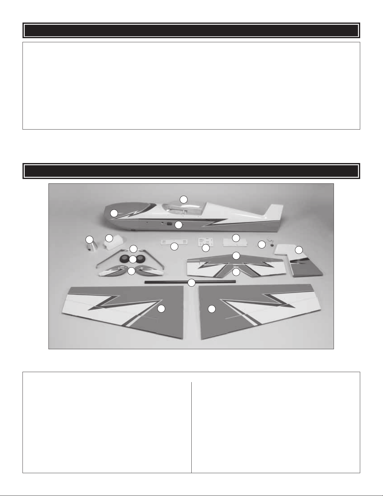
KIT CONTENTS
2
4
1 Cowl
2 Canopy Hatch
3 Fuselage
4 Spinner
5 Fuel Tank
6 Landing Gear (2)
7 Main Wheels (2)
8 Wheel Pants (L&R)
9 Fuel Tank Tray
10 Radio Tray
11 Battery Mounting Plate
1
3
5
6
7
8
9
17
10
16
18
11
14
15
12
13
Kit Contents
12 Horizontal Stabilizer
13 Elevators
14 Tail Gear Assembly
15 Rudder
16 Aluminum Wing Joiner
17 Left Wing Panel w/Aileron
18 Right Wing Panel w/Aileron
8
8
Page 9
SHRINK THE COVERING
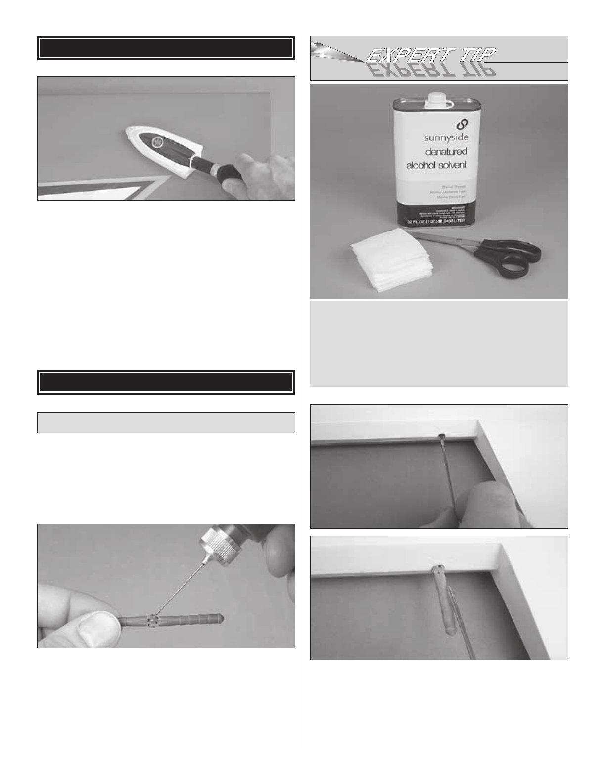
❏ 1. Examine the airframe for wrinkles in the covering or
areas where the covering isn’t adhered to the structure. Where
necessary, use a covering iron with a protective covering sock
to shrink any wrinkles and get the covering bonded to the
framework–use an iron temperature setting around 250° F
[120° C]. And use care o ver seams. If too m uch heat is applied
over seams and edges the cov ering will pull away. Note: Naptha
(lighter fl uid) can be used to remove any adhesiv e left from the
masking tape holding the control surfaces.
ASSEMBLE THE WINGS
During construction there will be several occasions where
epoxy cleanup will be necessary. Instead of wasting whole
paper towels, stack three or four paper towels on top
of each other and cut them into small squares. This will
conserve paper towels and the little squares are easier
to use. For epoxy clean up dampen the squares with
denatured alcohol.
Hinge the Ailerons
❏ 1. T est fi t each aileron to its matching wing with the hinges.
Note that the pivot point of the hinges should be centered on
the pivot point of the control surface–each hinge should be
exactly halfway in. Make any adjustments necessary for the
correct fi t.
❏ 2. Remov e the ailerons and take out the hinges . Add a small
drop of plastic-compatible oil to the pivot point of each hinge–be
careful not to get any oil on any other part of the hinges.
Note: When permanently hinging the ailerons to the wings in
the following step, use separate batches of 30-minute epoxy
for each wing. If you try to do it all at once, the epoxy might
harden before you fi nish.
❏ 3. Permanently join one of the ailerons to the matching
wing with 30-minute epoxy–a good way is to use a wire or a
toothpick to spread epoxy in each hinge hole of the aileron
and the wing. Coat one side of a hinge with epoxy and fi t it
into the wing. Install the remaining four hinges in that wing
half the same way. Coat the other end of the hinges that
are sticking out, then push the aileron all the way on until
9
Page 10
there is just enough space in the gap to see light through.
Wipe off any excess epoxy that squeezes out and move the
aileron up and down several times to center and align the
hinges. Hold the aileron to the wing with masking tape until
the epoxy hardens.
❏ 4. Hinge the other aileron to the other wing with a new
batch of 30-minute epoxy.
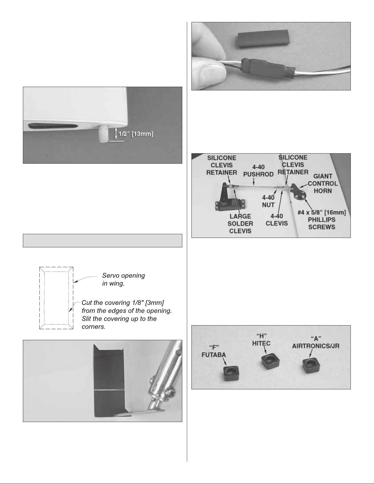
❏ 5. While you hav e some epoxy mix ed, glue two 5/16" x 1-1/4"
[8 x 33mm] hardwood incidence dowels into the root end of
each wing so that 1/2" [13mm] of each dowel protrudes.
❏ 6. After the epoxy on all the hinges has hardened, remove
the masking tape. Move the ailerons up and down to “break”
any epoxy from the hinge pins and get them moving freely.
❏ 2. Connect a 12" [305mm] servo extension wire to each
aileron servo (for Futaba servos, Hobbico servo extensions
(HCAM2100) were used). Secure each connection with
pieces of 3" [75mm] heat-shrink tubing cut in half. Use a heat
gun to shrink the tubing.
Refer to this photo while mounting the aileron servos
and hooking up the ailerons.
Hook Up the Ailerons
❏ 1. Cut the covering from the servo openings in the
bottom of the wings. Hint: First cut the covering 1/8" [3mm]
inside the edges of the opening. Then slit the covering up to
the corners and use a trim iron to seal the covering down
inside the opening.
❏ 3. Use the string in the wing or a wire with a hook bent
on the end to pull one of the servo wires through the servo
opening and down through the ribs out the end of one of the
wings. Place the servo in the opening. Fit the other servo in
the other wing the same way.
❏ 4. Drill 1/16" [1.6mm] holes in the wings for the servo mounting
screws. Temporarily mount the servos with the screws that came
with them. Remove the screws and take the servos out of the
openings. Harden the screw holes with a few drops of thin CA.
Allow the CA to harden, then mount the servos again.
❏ 5. Great Planes large-scale 1.5" [38mm] single-sided
servo arms with adapters (GPMM1105) are shown in this
manual. Select the plastic servo arm adapters for the servos
you will be using – “F” is for Futaba, “H” is for Hitec and “A” is
for Airtronics and JR.
❏ 6. If your aileron servos come with 3mm screws for
mounting the servo wheels, enlarge the hole in two metal
servo arms and plastic adapters included with this kit with a
#32 (.116" [3mm]) drill.
10
Page 11
❏ 7. Mount the servo arms to the aileron ser vos using the
appropriate servo adapters–the arms “point” toward the
wing tips. Note: If the screws that hold on the servo arms
have machine threads that go into metal output shafts in
the servos, use a drop of threadlocker on the screws before
mounting the arms.
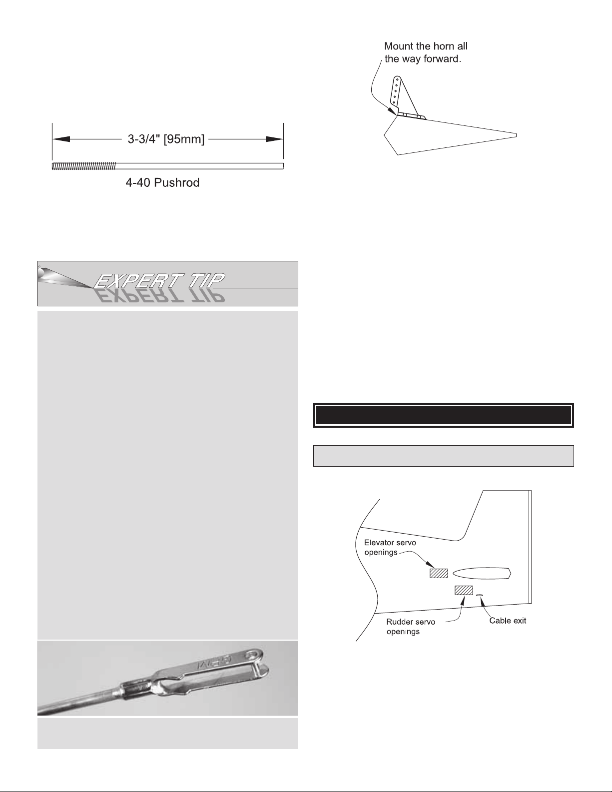
❏ 8. Make two 3-3/4" [95mm] aileron pushrods by cutting
the unthreaded end from two 4-40 x 12" [300mm] pushrods.
Solder a large metal clevis (the kind without threads) to each
aileron pushrod as shown in the Expert Tip that follows.
HOW T O SOLDER
❏ 9. Connect the ailerons to the aileron ser vos using the
hardware shown in the photo on page 10. Before mounting
the horns, drill 3/32" [2.4mm] holes for the screws. T emporarily
mount the horns with the #4 x 1/2" [13mm] screws. Remove
the screws and add a fe w drops of thin CA to each screw hole.
Remount the horns with the screws after the CA hardens.
Caution: Be certain you hav e used 4-40 threaded clevises–
not solder clevises on the threaded ends of the pushrods.
Set the wings aside while you work on the fuselage.
1. Use denatured alcohol or other solvent to thoroughly
clean the pushrod. Roughen the end of the pushrod with
coarse sandpaper where it is to be soldered.
2. Apply a few drops of soldering fl ux to the end of the
pushrod, then use a soldering iron or a torch to heat it. “Tin”
the heated area with silver solder (STAR2000) by applying
the solder to the end. The heat of the pushrod should melt
the solder–not the fl ame of the torch or soldering iron–thus
allowing the solder to fl ow. The end of the wire should be
coated with solder all the way around.
3. Place the clevis on the end of the pushrod. Add another
drop of fl ux, then heat and add solder. The same as
before, the heat of the parts being soldered should melt
the solder, thus allowing it to fl ow. Allow the joint to cool
naturally without disturbing. Avoid excess blobs, but make
certain the joint is thoroughly soldered. The solder should
be shiny, not rough. If necessary , reheat the joint and allo w
to cool.
4. Immediately after the solder has solidifi ed, but while it
is still hot, use a cloth to quickly wipe off the fl ux before it
hardens. Important: After the joint cools, coat with oil to
prevent rust. Note: Do not use the acid fl ux that comes
with silver solder for electrical soldering.
ASSEMBLE THE FUSELAGE
Mount the Horizontal Stabilizer
This is what a properly soldered clevis looks like–shiny
solder with good fl ow, no blobs, fl ux removed.
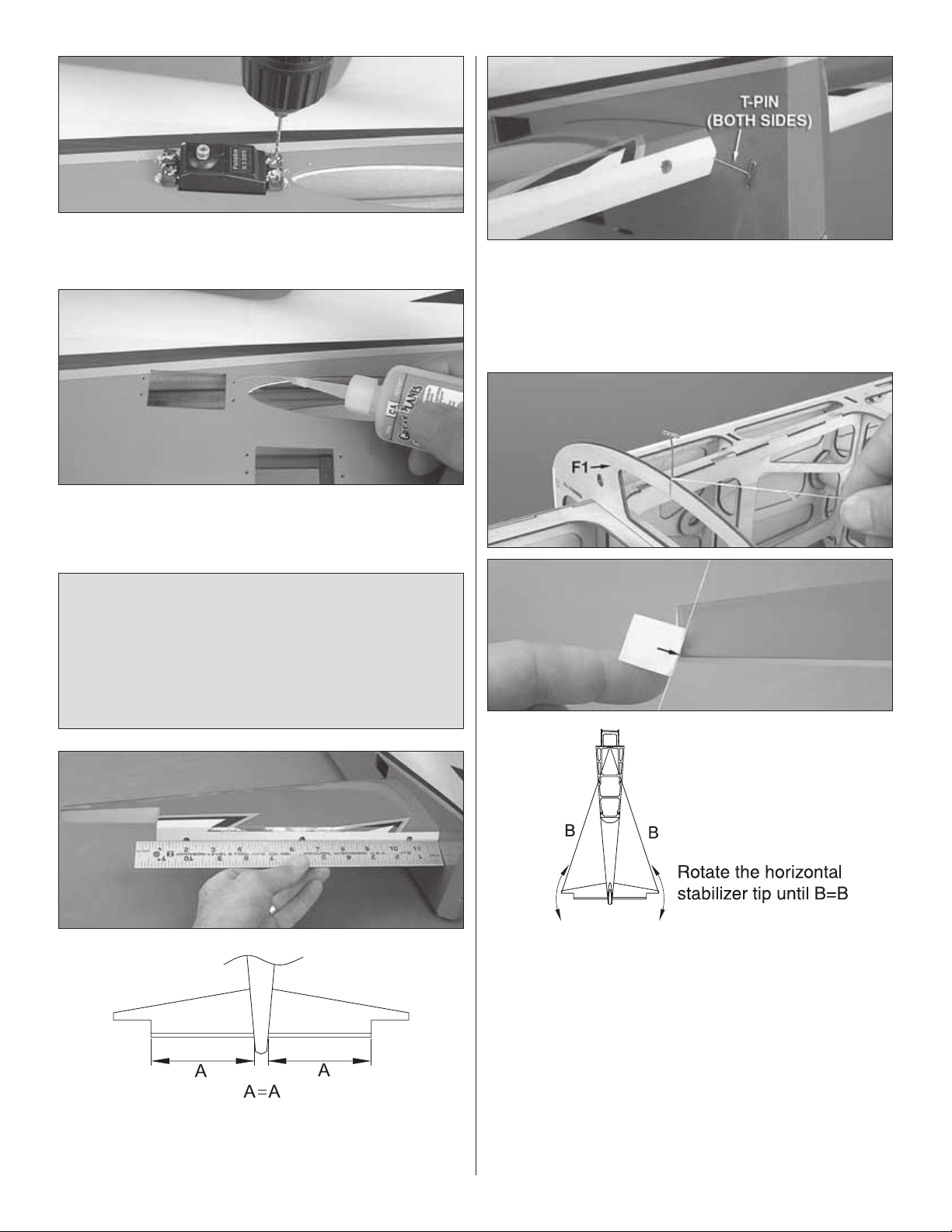
❏ 1. The same as was done for the aileron servo openings in
the wings, cut the covering from the elev ator servo openings
in both sides of the fuselage and use a trim iron to seal the
edges of the covering down inside. If not using the pull/pull
rudder servo setup and mounting the rudder servos outside the
fuselage, cut the covering from the rudder servo openings
too. Also cut the cov ering from the openings for the horizontal
stabilizer and, if mounting the rudder servos internally with
the pull/pull setup, cut the slots for the cab le exits.
11
Page 12
❏ 2. Place each servo in its opening and drill 1/16" [1.6mm]
holes for the mounting screws.
❏ 3. Temporarily mount each servo with the screws supplied
with your radio system. Remove the screws and add a few
drops of thin CA to each hole.
Note: The following stab alignment procedure may appear
to be extensive, but these are the steps necessary to build
a model with a properly-aligned horizontal stabilizer that will
fl y correctly. You could skip all the alignment steps and just
eyeball it, but you may end up with a crooked model that
won’t fl y straight. Please follow all of the instructions and
take your time to end up with an airplane that is straight
and true.
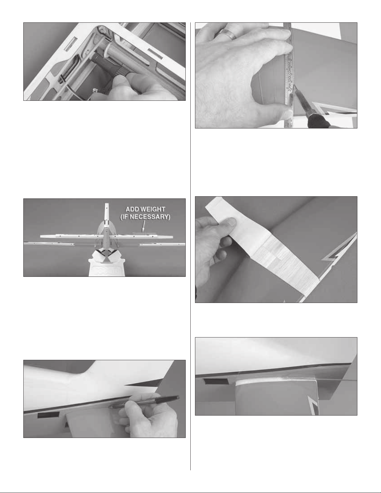
❏ 5. Once you have the trailing edge centered, stick large
T-pins through the trailing edge tightly against both sides of
the fuselage. This will keep the trailing edge centered while
rotating the leading edge in the next step.
❏ 4. Slide the stab into the fuselage. Center the trailing edge
(TE) in the fuselage by taking accurate measurements on
both sides.
❏ 6. Push another T-pin through the top of F1 at the
centerline. Tie a small loop in one end of an approximately
60" [1.5m] piece of non-elastic string (such as K+S or Kevlar
fi shing string). Fold a piece of masking tape over the string
near the other end and mark an arrow on it. Swing the string
over to the tip on one side of the stab and slide the tape
along the string until the arrow aligns with the tip. Swing the
string over to the same spot on the other side of the stab and
rotate the stab. Move the tape until both sides are the same
and the stab is squared.
One more alignment procedure to go…
12
Page 13
❏ 7. Now that the stab is centered, temporarily mount the
wing to the fuselage with the wing tube and the wing bolts.
Suggestion: Access to the wing bolts will be much easier
with a Great Planes 4-in-1 Installation Tool (GPMR8035).
This will be especially helpful when you get to the fl ying fi eld
and need to get the wing bolts tight.
❏ 8. Standing about 6' [2m] behind the model, view the
alignment of the stab and wing. If the stab is not parallel with
the wing, it will take just a few ounces of weight to “dial it in.”
Place incrementally increasing amounts of weight on the high
side of the stab until you can get it to align with the wing.
❏ 10. Take the T-pins out of the stab and take the stab out
of the fuselage. Use a soldering iron with a small tip to melt
through the covering 1/32" to 1/16" [.5 to 1.5mm] inside the
lines you marked all the way around–use a fl exible, metal
straightedge to guide the soldering iron. If you don’t have a
soldering iron, a sharp hobby knife could also be used to cut
the covering, but great care must be used not to cut into the
balsa underneath. Otherwise, the stab will be weakened.
❏ 11. Peel the covering from the middle of the stab.
❏ 9. No w that y ou kno w ho w much (if an y) w eight it will tak e
to get the stab to align with the wing, take off the weight, set
it aside, and use a ballpoint pen to carefully mark the sides
of the fuselage all the way around both sides of the stab.
Now that all the preliminary work has been done, the stab
can fi nally be glued into position.
❏ 12. Apply liberal beads of epo xy all the way around the top
and bottom of the stab just inside the edges of the covering
you cut where the stab will join the fuselage. Slide the stab
into position. Slide it another 1/4" [6mm] out the other side
as shown. Apply more epo xy all the wa y around the e xposed
balsa, then slide the stab back into place. Wipe away e xcess
epoxy, use the T-pins and the pin and string to re center the
13
Page 14
stab, add any weight that may have been necessary to align
the stab with the wing, wipe away more epo xy that ma y ha v e
dripped out, check the alignment once more, then do not
disturb the model until the epoxy has hardened.
Hinge the Elevators & Rudder
Hinging the elevators and rudder is done the same
as you did the ailerons, but we’ll give you a brief runthrough anyway.
❏ 1. If you haven’t yet done so, remove the wings from
the fuselage.
❏ 2. T est fi t both elevators to the stab and the rudder to the
vertical stab (fi n) with the hinges. Make sure the hinges are
centered and make any adjustments necessary.
❏ 3. Remove the elevators and r udder and take out all the
hinges. The same way you did for the aileron hinges, add a
small drop of oil to the pivot point of each hinge.
❏ 2. The same as was done for the servo e xtension wires on
the aileron servos, secure the connections with 3" [75mm]
pieces of heat-shrink tubing cut in half.
Refer to this photo while hooking up the external rudder
servos and elevator servos.
❏ 3. Guide the rudder servo wires down through the fuselage
and mount the servos. Note that the servo output shafts on
both rudder servos are toward the aft end of the fuselage.
❏ 4. Permanently hinge the elevators to the stab and the rudder
to the fi n–don’t forget to use separate batches of 30-minute
epoxy for each control surf ace–otherwise y ou ma y run out of
working time with the epoxy.
❏ 5. After the epoxy on all the hinges has hardened, remove
the masking tape and rapidly move the surfaces to “break”
any epoxy from the hinge pins and get the surfaces moving
freely again.
If mounting the rudder servos inside the fuselage with the
pull/pull cables, skip ahead to “Hook up the Elevators.”
(Remember, gas engine installations should use the aft,
external rudder servo location.)
❏ 4. Select the plastic ser vo arm adapters for the servos
you will be using – “F” is for Futaba, “H” is for Hitec and “A” is
for Airtronics and JR.
❏ 5. Same as the aileron servos, use the 3mm screws
supplied with your radio system to mount the servo wheels/
arms. Drill out the hole in the metal servo arms and plastic
adapters included with this kit with a #32 (.116" [3mm]) drill.
❏ 6. Temporarily mount the ser vo arms to the ser vos using
the appropriate servo adapters and servo screws.
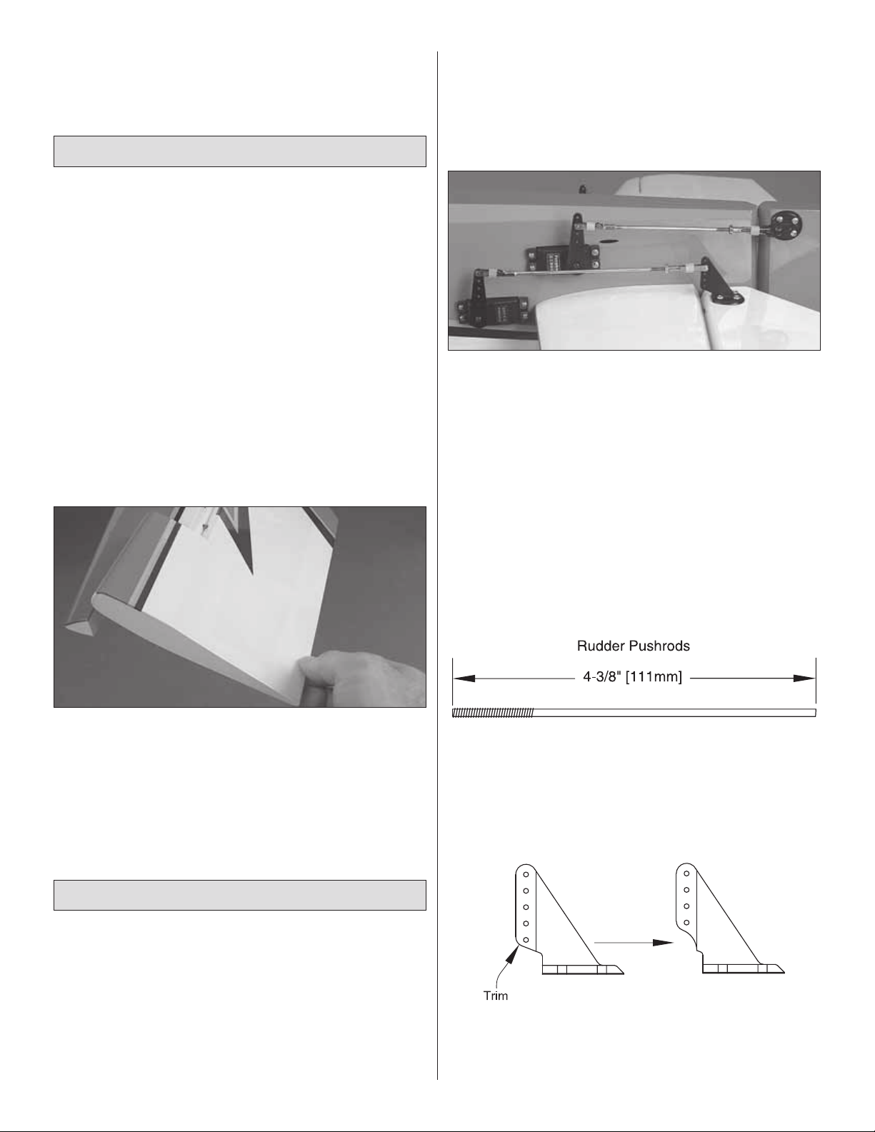
❏ 7. Make two 4-3/8" [111mm] rudder pushrods from two
4-40 x 12" [300mm] pushrods. Use the same techniques
described for making the aileron pushrods to solder large
metal clevises to the ends of the rudder pushrods and make
sure the clevises on the threaded end of the pushrods are
the threaded kind.
Hook Up the External Rudder Servos
❏ 1. If mounting the receiver to the forward servo tray,
connect 36" [910mm] servo extension wires to the rudder
servos. If mounting the receiver to the aft servo tray,
connect 24" [610mm] servo extension wires to the rudder
servos. Later, the rudder servos will be linked with a “Y”
connector and connected to one channel in the receiver. If
not yet certain where you will be mounting the receiver, you
may connect the extensions later.
❏ 8. Trim the bottom hole from two control horns as shown.
❏ 9. Connect the rudder pushrods to the rudder servo arms,
then connect the rudder horns to the other end of the rudder
14
Page 15

pushrods. Hold the horns to the rudder and drill 3/32" [2.4mm]
holes 1/2" [13mm] deep for the mounting screws – same as
the aileron horns, the rudder horns should be mounted all the
way forward. Mount the horns to the rudder with #4 x 1/2"
[13mm] screws. Don’t forget to remo ve the screws . Harden the
holes with a few drops of thin CA, allow to harden, and then
remount the horns.
Hook Up the Elevators
Note that, because the elevator servos mov e in opposition,
they must be connected to two diff erent channels and linked
electronically via mixing in the transmitter (or connected to
a Futaba Servo SR-10 Dual Servo Reverser (FUTM4150)
so that one of the servos can be reversed).
Refer to the previous photo showing the servos while
hooking up the elevators.
❏ 1. If mounting the receiver to the forward servo tray,
connect 36" [910mm] servo extension wires to the elevator
servos. If mounting the receiver to the aft servo tray, connect
24" [610mm] servo extension wires to the elevator servos. If
not yet certain where you will be mounting the receiver, you
may connect the extensions later.
the aileron pushrods to solder large metal solder clevises to
the ends of the elevator pushrods.
❏ 8. Connect the pushrods to the servo arms. Then, connect
the horns to the other end of the pushrods. Hold the horns
to the elevators and drill 3/32" [2.4mm] holes 1/2" [13mm]
deep for the mounting screws – same as the aileron and
rudder horns, the elevator horns should be mounted all the
way forward. Mount the horns to the elevators with #4 x 1/2"
[13mm] screws. Don’t forget to remove the screws, harden
the holes with a few drops of thin CA and allow to harden
before remounting the horns.
If you already mounted the rudder serv os in the back of the
fuselage, skip ahead to page 18 and mount the tail gear .
Mount the Pull/Pull Rudder Servos
❏ 2. The same as was done for the servo e xtension wires on
the aileron servos, secure the connections with 3" [75mm]
pieces of heat-shrink tubing cut in half.
❏ 3. Guide the elevator servo wires down through the
fuselage and mount the servos. Note that the servo output
shafts are forward.
❏ 4. Select the plastic servo arm adapters for your servos
– “F” is for Futaba, “H” is for Hitec and “A” is for Airtronics
and JR.
❏ 5. Same as the aileron servos, use the 3mm screws
supplied with your radio system to mount the servo wheels/
arms. Drill out the hole in the metal servo arms and plastic
adapters included with this kit with a #32 (.116" [3mm]) drill.
❏ 6. Temporarily mount the ser vo arms to the ser vos using
the appropriate servo adapters and servo screws.
❏ 7. Make two 5-1/2" [140mm] elevator pushrods from two
4-40 x 12" [300mm] pushrods. If mounting the rudder servos
inside the fuselage with the pull/pull setup, save the leftover
pieces of pushrod you cut off for connecting the rudder
servos later. Use the same techniques described for making
❏ 1. Mount the rudder servos in the rudder servo tray in
the fuselage by drilling 1/16" [1.6mm] holes for the screws,
temporarily installing, removing, and hardening the holes with
thin CA. Connect both servos to a dual servo connector. Then
temporarily connect the connector into the rudder channel in your
receiver. Also connect a receiver battery and an on/off switch to
the receiver so you can operate the servos with the transmitter.
Refer to this photo for the following two steps.
❏ 2. Turn on the transmitter and receiver and center the
rudder trim on the transmitter. With the rudder servos
powered up and the trims centered, mount a servo wheel
to each servo. Use the servo arm screws that came with the
servos to mount the plywood servo arm drilling template to
the servos over the wheels.
❏ 3. With your radio system still on, use the holes in the
plywood servo arm drilling template as a guide to drill 3/32"
[2.4mm] holes through the servo wheels. Now you may turn
off the radio.
15
Page 16

❏ 4. Remove the plywood servo arm drilling template.
Keeping the servo wheel in the same orientation as when it
was on the servo, remov e the servo wheel from the aft rudder
servo. Mount one of the aluminum pull/pull rudder servo
arms to the wheel as shown with four 2-56 x 3/8" [10mm]
screws and 2-56 nuts–be certain to use threadlocker on
the threads. Optional: After mounting the servo arm, cut off
the screws, then fi le the ends fl at and smooth.
transmitter and receiver. Connect the servo arms on the
rudder servos with the rudder pushrods and four 4-40 x 1/4"
[6.4mm] SHCS. Turn off the radio.
Hook Up the Pull/Pull Rudder Cables
❏ 1. Cut the supplied braided steel cable into two equal-
length pieces. (There should be enough cable to make two
sets–in case you make a mistake.) Set one of the pieces
aside in case you need it as a spare.
❏ 5. Mount two large screw-lock pushrod connectors in the
outer holes on each end of the servo arm and secure the
connectors with a one-way push-on washer. Remount the
servo wheel with the aluminum servo arm to the servo.
Be certain to install the screw that retains the wheel–use
threadlocker if they are machine-thread screws.
❏ 6. Mount and setup the other rudder pull/pull servo arm
to the servo wheel on the other rudder servo.
Refer to this photo of the completed rudder servo hookup
while performing the installation in the following steps.
❏ ❏ 2. Cut the other piece of cable in half again. Slide a
copper swage and a threaded brass coupler onto one end of
one of the cables. There should be approximately 1" [25mm]
of cable coming from the coupler.
❏ ❏ 3. Loop the cab le ov er and slip it into the s wage . Adjust
the position of the swage so the cable mak es a loop and there
is approximately 3/8" [10mm] between the end of the swage
and the coupler. Squeeze the swage tightly with pliers.
❏ 7. Make two 3" [75mm] rudder pushrods from the lefto ver
4-40 pushrod wire you saved from the elevators. Turn on the
❏ ❏ 4. T rim the bottom hole from two control horns as shown.
16
Page 17

❏ ❏ 5. Thread a 4-40 nut and a 4-40 cle vis onto the threaded
coupler on the cable. Fit a silicone clevis retainer over the
clevis. Connect the clevis to what used to be the middle hole
in one of the control horns you prepared, but now is the third
hole from the top.
❏ ❏ 6. Slide one of the pieces of blue heat-shrink tubing
over the cable. Shrink the heat-shrink tubing over the cable
somewhere near the middle (you will still be able to slide
the tubing after it has been shrunk). Position the heat-shrink
tubing so the middle of the tube is 18-3/4" [475mm] from
the pin in the clevis. Slide the heat-shrink tubing over a
couple more inches and coat the cable with a few drops of
medium CA where the tubing used to be. Slide the heatshrink tubing back and forth a few times to get the CA inside,
then reposition the tubing as previously described so it is
centered 18-3/4" [475mm] from the pin.
❏ 7. While the CA in the heat-shrink tubing is hardening,
repeat steps 2 through 6 for the other cable.
❏ 8. Slide the other end of one of the cables through the
exit slot in the right side of the fuselage under the horizontal
stabilizer. Reach down into the fuselage and pull the cable up
to the rudder servos.
❏ 9. Hold the rudder centered with a few pieces of
masking tape.
❏ 10. Using one hand to hold the cable to the left side of the
servo arm on the aft rudder ser vo (the cables cross inside
the fuselage), use your other hand to hold the control horn
to the right side of the rudder so the cable aligns with the
exit slot.
❏ 12. Mount the other cable to the other side of the rudder
the same way.
❏ 13. Connect another 4-40 clevis, a 4-40 nut and a silicone
retainer to another threaded coupler.
❏ 14. Turn on the transmitter and receiver. Slide a swage
over the pull/pull cable in the fuselage that is connected to the
horn on the right side of the rudder. Loop the cable through
the coupler. Connect the clevis on the cable to the hole in the
servo arm. With the rudder servos centered, pull the cable
tight and loop the cable around the threaded coupler. Then,
slide the swage over the end of the loop and squeeze the
swage with pliers. Cut off the excess cable.
❏ 15. Adjust the tension in the cable by disconnecting one
of the clevises on either end of the cable and threading or
unthreading the clevis on the coupler. The cable should be
somewhat taut–about as tight as a loose guitar string–but
not so tight that it puts much strain on the servos, clevises or
rudder. Reconnect the clevis.
❏ 16. Connect the other rudder cable to the other side of the
rudder servo arm the same way.
❏ 17. Remove the masking tape from the rudder. Give
the rudder a “test run” by working the controls with your
radio. With the system powered up and the rudder trim still
centered, center the rudder by adjusting the length of the
cables and adjusting the cable tension. With the offset servo
arm, cable tension should be about the same with the rudder
centered as it is when the rudder is at full throw.
❏ 18. Once the rudder setup has been fi nalized, lock the
clevises to the threaded couplers by tightening the 4-40 nuts .
❏ 11. Mount the horn to the rudder in this location by drilling
four 3/32" [2.4mm] holes and using four #4 x 1/2" [13mm]
screws–don’t forget to harden the holes with thin CA.
❏ 19. Cut another piece of heat-shrink tubing to secure the
connection between the rudder servos and the dual servo
17
Page 18

connector. If using a Futaba dual servo connector, the heatshrink tubing will have to be stretched to fi t over the connector
by slipping it over long nose pliers and holding it open to
stretch the heat-shrink tubing. Fit the heat-shrink tubing ov er
the connector, and then shrink the tubing.
Mount the Tail Gear
Refer to this photo and the sketch while mounting the
tail gear.
❏ 4. Drill a 5/32" [4mm] hole through the middle of the bottom
of the rudder 4" [100mm] from the leading edge. Fit the tiller
spring into the steering post, inser t the post onto the hole in
the rudder, and permanently glue in the post with thin CA.
Note: If you prefer working on the model with it resting on
its landing gear rather than sitting in your building stand, y ou
may go ahead and mount the main landing gear (with or
without the wheels for now) at this time. If you want to mount
the landing gear, use six 6-32 x 3/4" [19mm] SHCS, #6 lock
washers, #6 fl at washers and a drop of threadlocker on the
threads. If you want to mount the wheels too skip ahead to
“Mount the Landing Gear” on page 32.
Mount the Engine or Electric Motor
❏ 1. Turn to the back cover page and cut out the mounting
template for the type of power system you will be using–one
template is for the Fuji-Imvac BT-43EI-2 gas engine and
the other is for both the included Great Planes 1.20 to 1.80
adjustable engine mount for glow engines and the ElectriFly
Brushless Motor Mount for extra large motors (GPMG1265
– not included).
❏ 1. Cut the covering from the hole in the bottom of the
fuselage for the nylon tail gear bearing. Roughen the
bearing with medium-grit sandpaper. Then, use medium CA
to securely glue the tail gear bearing into position. Use care
not to get any glue inside the bearing.
❏ 2. Mount the alumin um collar to the tail gear wire with the
set screw and a drop of threadlocker applied to the threads.
Use the hex wrench included with the tail gear (or your own
1/16" [1.6mm] hex wrench) to tighten the set screw.
❏ 3. Drill 1/16" [1.6mm] holes into the bottom of the fuselage
for the bracket mounting screws. Temporarily mount the
bracket and the tail gear with #2 x 1/2" [13mm] screws.
Remove the screws , set the brac ket aside , add a drop or two
of thin CA to each screw hole, and allow to harden. Then,
remount the bracket with the screws.
❏ 2. Tape the template to the fi rewall with the cross marks
on the template aligned with the cross marks on the fi rewall.
Use a piece of wire sharpened on the end or a T-pin to mark
the cross marks for the bolt holes in the template onto the
fi rewall. Note: If mounting a gas engine different than the
Fuji-Imvac BT-43EI-2, use the mounting template that came
with your engine or make your own template, or center the
engine on the cross marks and use the mounting holes in
the engine to mark the fi rewall. Note: If using the O.S. 1.60
FX, also mark the location for the throttle pushrod.
❏ 3. Remove the template. Drill 1/16" [1.6mm] pilot holes at
all the marks. If mounting the Fuji-Imvac BT-43EI-2 engine,
enlarge the pilot holes with a 1/4" [6.4mm] drill for 10-32 or
10-24 blind nuts. If using the included 1.20 to 1.80 adjustab le
engine mount for glow engines or the ElectriFly motor mount,
enlarge the pilot holes with a 3/16" [4.8mm] drill for the
included 8-32 blind nuts. If using the O.S. 1.60, also enlarge
the pilot hole for the throttle with a 3/16" [4.8mm] drill.
18
Page 19

❏ 4. For the Fuji-Imvac BT-43EI-2 engine installation or other
gas engines, use one of your #10 engine mounting bolts (not
included) and a couple of washers to draw the blind n uts (not
included) into the back of the fi rewall. If using the included
adjustable engine mount, use an 8-32 x 1" [25mm] SHCS
and a couple of washers to pull the included 8-32 blind nuts
into the back of the fi rewall.
If mounting an electric motor skip to “Mount the Electric
Motor” on page 26.
❏ 5. If using a gas engine, mount the engine with the engine
mounting bolts and lock washers (not included), then skip
to “Assemble the Fuel Tank.” If mounting a glow engine,
mount the engine mount halves to the fi rewall with four 8-32 x
1-1/4" [32mm] SHCS and #8 fl at washers and lock washers ,
but do not tighten the screws all the way yet.
❏ 6. With the fuselage lying on its left side in your building
stand, place the engine on the engine mount. Adjust the tw o
halves of the engine mount to fi t the engine. Then tighten the
engine mount bolts.
❏ 9. Use an 8-32 tap to cut threads into the holes. Remount
the engine mount to the fi rewall, but don’t tighten the bolts
yet. Mount the engine to the mount with f our 8-32 x 1" [25mm]
SHCS and #8 lock washers. Center the engine mount on the
engine mount bolts, then fully tighten the engine mount bolts.
ASSEMBLE THE FUEL T ANK
If using a gasoline-powered engine the fuel tank setup
will have to be converted to work with gas using the
hardware listed in the front of the manual. Follow these
instructions for assembling your fuel tank f or the type of
engine you are using.
Glow Engines
❏ 1. Cut tw o of the aluminum tubes that came in the fuel tank
to a length of 1-1/2" [40mm]. (This can be done b y rolling the
tubing on your workbench with a #11 blade.) Assemble the
stopper as shown in the photo. Bend the long tube so it will
be at the top of the tank. Cut the fuel lines so the clunks
cannot contact the back of the tank–otherwise they could
get stuck. Note that one of the lines will be used for fueling
and defueling and the other line will be the pickup line that
goes to the carburetor. The bent tube will be connected to
the vent/pressure line that will go to the pressure tap on the
muffl er. Proceed to step 4 to fi nish assembling the fuel tank.
❏ 7. Use a small C-clamp or two to hold the engine to the
mount so that the front of the drive washer (or the backplate
of the spinner) is 6-3/4" [170mm] from the fi rewall. Use a
Great Planes Dead Center™ Hole Locator or a drill bit to
mark the engine mounting holes into the engine mount.
❏ 8. Take the engine off the mount. If you have a drill press
that will drill the holes squarely, remove the mount from the
fi rewall and drill #29 holes at the marks. If you don’t have a
drill press, you can leave the mount attached to the fuselage
for drilling the holes.
Gas Engines
❏ 1. Cut one of the brass tubes included with the Sullivan
conversion kit in half, making two approximately 1-3/4"
[45mm] tubes. Solder a Du-Bro fuel line barb onto one end
of each of the three tubes.
19
Page 20

❏ 2. Assemble the stopper, tubes and metal plates. Solder
another fuel line barb onto the ends of the short tubes. Bend
the brass vent/overfl ow tube upward so it will be at the top
of the tank.
❏ 3. Connect the fuel tubing to the short tubes and the
clunks–cut the lines so that the clunks cannot contact the
back of the tank–otherwise they could get stuck. Note that
one of the lines will be used for fueling and defueling and the
other line will be the pickup line that goes to the carburetor.
The bent tube will be the vent/overfl ow line that will be
connected to a line that exits the bottom of the fuselage.
Important: Secure both ends of both fuel tubes with small
nylon ties. This is an important measure that must be taken
to be sure the lines remain attached inside the tank.
Insert the stopper so the vent tube will be at the top of the
tank. Then tighten the screw to squish the stopper and seal
the tank. Shake the tank to make sure the clunks can move
around and the fuel lines are not too long. If necessary,
remove the stopper and shorten the lines.
Mount the Fuel Tank
❏ 1. Glue the plywood fuel tank tray former inside the
fuselage as shown.
❏ 2. Use a hobby knife or sandpaper to bevel the front
edges of the plywood fuel tank tray (the front is the end with
the longer tab). The side with the beveled edges will now be
the bottom. (There is another photo showing the bevel in
step 1, on page 26.)
VENT/PRESSURE
(OR OVERFLOW)
One line is for fueling/defueling and
the other is for fuel pickup to the
carburetor (it doesn’t matter which).
❏ 4. Wr ite “TOP” on the back of the tank so you will know
which way to install it after inserting the stopper assembly.
❏ 3. Cut two of the 12" [300mm] strips of the rougher “hook”
side of the included V elcro material into two 8" [200mm] strips.
Cut two more of the softer “loop” strips to the same length.
Make two fuel tank straps by overlapping 2-1/2" [60mm] of
the ends of the straps. Use medium CA to glue the straps to
the bottom of the fuel tank tra y in alignment with the cutouts
in the sides.
20
Page 21

❏ 4. Securely glue the plywood fuel tank tray into position.
❏ 5. Mount the fuel tank to the tray with the Velcro straps
and 1/4" [6mm] R/C foam rubber between the bottom of the
tank and the tray.
Refer to the photos below while hooking up the fuel lines.
(Photos of the gas installation are shown, but the
instructions and suggestions in the photos apply to
glow engines as well. Note: Tygon fuel tubing is shown
in the photos.)
❏ 6. Plan the fuel line setup thinking about how you will be
fueling the model, where the fueling and vent/pressure lines
will be located, how to guide the fuel lines around the muffl er
and engine and where the lines will go through. There are also
plywood dual and a single fueling line mounts that could
be used to mount the fueling and vent lines, or you could use
another method for fueling the model such as fuel line dots
or a fuel fi ller valve. The dual mount in the photo secures the
fueling line and the vent line for gas engines. Both lines are
closed during transport (to keep any remaining fuel in the
tank from leaking), but the vent line is open whenever the
engine is running. The fueling line is open only when fueling
or defueling the model.
❏ 7. Once you have determined how you will be routing
the fuel lines and fueling the model, remove the engine if
necessary, then drill 1/4" [6.4mm] holes through the fi rewall
or other parts of the engine box for all the lines.
❏ 8. Assemble the fueling line mounts and glue them into
position. Coat the mount with epoxy or fuelproof paint, allow
to dry, then connect the lines.
21
Page 22

Hook Up the Throttle
FORWARD RADIO TRAY
FORWARD RADIO TRAY
AFT RADIO TRAY
AFT RADIO TRAY
❏ 1. Determine which plywood radio tray you will be using–
the aft radio tray should be used for gas engine installations
because it positions the throttle servo, receiver battery and
receiver away from any potential RF noise that may be
generated by the engine. Using the aft radio tray also counter
balances the extra weight of a gas engine, reducing the amount
of any tail weight that may be required. For C.G. purposes, the
forward radio tray is recommended f or glo w engines. The aft
tray is recommended f or electric motor installations.
❏ 2. Once you ha ve decided which radio tray to use, determine
which way you will be mounting the tray so the throttle servo
will be on the same side as the throttle arm on the carburetor
(for gas and glow engines). Note: There is an alternate throttle
servo location on the side of the engine box. Do not mount
your throttle servo on the engine box if powering this model
with a spark-ignition engine–all radio components (receiver,
Rx battery, switch, servos) in planes with gas engines should
be a minimum of 10" [250mm] from any engine components
(engine, module, ignition battery, ignition on/off switch).
Otherwise, electrical “noise” from the engine ma y cause r adio
interference. If preferred, the throttle servo could be mounted
on the engine box for glo w engines.
❏ 3. Securely epoxy both 3/8" x 3/8" x 4" [10 x 10 x 100mm]
radio tray mounting rails inside the fuselage for the location
you will be using. The rails should be centered across the
horizontal members and approximately 1/8" [3mm] below
the top edge.
❏ 4. Glue the plywood throttle servo mount doublers to
the bottom of whichever radio tray you will be using. Drill
1/16" [1.6mm] holes through the tray and doublers and
mount the throttle servo in the tray–as alwa ys , don’t f orget to
harden the holes with thin CA.
22
Page 23

❏ 5. Make mounting straps from the included Velcro strips
by cutting them to the correct length for the receiver and
battery. Mount the receiver and battery to the tray with 1/4"
[6mm] R/C foam rubber. If you want you could use CA to
glue the Velcro to the bottom of the tray. This will make refastening the straps around the battery and receiver easier if
you ever remove and re-install them later.
❏ 6. Mount the radio tray to the rails in the fuselage with four
#2 x 1/2" [13mm] screws and #2 washers–again, don’t forget
to harden the screw holes with thin CA.
❏ 7. Hook up the throttle as instructed below for the type of
engine you are using.
Glow Engine Throttle Hookup
❏ 1. T emporarily mount the muffl er to the engine so you will know
where to locate the throttle pushrod so it won’t interfere with the
muffl er. If you haven’t yet done so, mark the fi rewall where the
throttle pushrod will go through and drill a 3/16" [4.8mm] hole
at that mark (this will probably require temporary removal of the
engine). Also be certain to drill the hole where the pushrod will
not interfere with the fuel tank behind the fi rewall and do not drill
into the fuel tank.
❏ 2. Hook up the throttle using the hardware listed below.
Glow engine throttle pushrod hardware:
❏ 2-56 x 36" [910mm] wire pushrod
❏ 3/16" x 36" [4.8 x 910mm] gray pushrod guide tube
On the servo end:
❏ brass screw-lock pushrod connector
❏ nylon retainer
❏ 4-40 x 1/8" [3.2mm] SHCS
On the engine end:
❏ nylon ball link
❏ 0-80 ball link ball
❏ 0-80 nut
Note that, for the O.S. 1.60 FX shown, the pushrod goes
through the fi rewall at a slight angle toward the servo, so you
may need to use a hobby knife to angle the hole accordingly.
Use one of the plywood pushrod supports to secure the aft
end of the pushrod near the throttle servo. Cut the gray pushrod
guide tube to the correct length, then use coarse sandpaper to
roughen both ends where it goes through the fi rewall and the
pushrod support. Glue the tube and the support into position
with medium CA. Cut the pushrod wire to the correct length
and make a slight bend near the end as necessary to align
with the ball link ball on the carburetor arm.
23
Page 24

Gas Engine Throttle Hookup
❏ 1. If using a Fuji-Imvac BT-43EI-2, use an extended 3/16"
[4.8mm] drill bit or a 3/16" [4.8mm] brass tube sharpened on
the end to drill a hole for the gray pushrod guide tube where
shown in the following photo. If using a different gas engine,
and if there’s a chance the muffl er might be in the way of the
throttle pushrod, temporarily mount the muffl er to the engine
to make sure you locate the throttle pushrod where it won’t
interfere with the muffl er. Mark the fi rewall where the throttle
pushrod will go through and drill a 3/16" [4.8mm] hole at that
mark (this will probably require temporary removal of the
engine–also be certain to drill the hole where the pushrod
will not interfere with the fuel tank behind the fi rewall.
On the engine end:
❏ 2-56 x 1" [25mm] threaded rod
❏ nylon ball link
❏ 2-56 ball link ball
❏ 2-56 nut
Cut the gray pushrod guide tube to the correct length, then
use coarse sandpaper to roughen both ends where it goes
through the fi rewall and where it gets glued to the pushrod
supports. Trim the plywood pushrod supports as necessary
and use them to secure guide tube where shown. Securely
glue the pushrod tube and the supports into position with
medium CA.
Mount the Ignition Module, Ignition Battery &
Ignition On/Off Switch (gas engines only)
Refer to these photos while mounting the ignition
module and ignition battery.
❏ 2. Hook up the throttle using the hardware listed below.
Gas engine throttle pushrod hardware:
❏ 36" [910mm] white, nylon pushrod
❏ 3/16" x 36" [4.8 x 910mm] gray pushrod guide tube
On the servo end:
❏ 2-56 x 1" [25mm] threaded rod,
❏ nylon clevis
❏ silicone clevis retainer
❏ 1. The same as when you were routing the fuel lines and
hooking up the fuel tank, read the instructions and plan the
battery and module installation, making sure all the wires
will reach wherever they are supposed to go. Don’t forget
about the ignition on/off switch–a heavy-duty on/off switch
from your radio system could be used for this. One way to
24
Page 25

determine where to mount the battery, module and switch
would be to connect all the wires and see how much distance
between them is required.
❏ 2. Glue one of the plywood s witch mounting plates for the
engine ignition switch inside the fuselage. Choose the type of
mount for the on/off switch you will be using–there is one
switch mounting plate for a heavy-duty Futaba switch and
one for a heavy-duty Hobbico Pro switch. Both switch plates
also have a mounting port for an Ernst charge receptacle
for charging and checking the voltage of the ignition battery.
If using a different type of on/off switch, modify one of the
switch mounting plates as necessary.
alternate set of mounting tab sides that don’t have the cutouts should you decide to remove the mounting tabs from
the Fuji-Imvac module or if you are using a diff erent module.)
If using an ignition module that doesn’t fi t the mount, make
your own mount or use small screw hooks (not provided) to
mount the ignition module with rubber bands.
❏ 4. Make the ignition battery mount by gluing the plywood
strips to one side of the mounting plate.
❏ 5. Fuelproof the battery mount and the ignition mount with
epoxy or fuelproof paint. After the paint dries, apply strips of
1/8" [3mm] foam tape (GPMQ4424) to the mount to cushion
the module.
❏ 6. Use more Velcro strips to mount your ignition battery
to the battery mount with 1/4" [6mm] R/C foam rubber in
between. Securely glue the ignition mount and the battery
mount into position (where shown in the photo).
❏ 7. Mount the ignition on/off s witch and a charge receptacle
to the switch mounting plate.
❏ 8. Connect the wires from the ignition module to the
connector plug exiting from the engine, to the spark plug,
and to the on/off switch connector. Connect the ground wire
to a bolt on the engine. Connect the ignition battery to the on/
off switch. Make sure none of the wiring contacts anything
that could melt it (especially the muffl er).
❏ 3. If using the Fuji-Imvac BT-43EI-2 engine, glue together
the plywood ignition module mount as shown. (There is an
Go to “Final Assembly” on page 28.
25
Page 26

Mount the Electric Motor
❏ 1. If you haven’t yet done so, mount the prop adapter to
the electric motor using threadlocker on the threads.
❏ 2. Separate the front and back halves of the ElectriFly
motor mount. If necessary, remove the collar from the motor
shaft with a 2mm hex wrench. Mount the motor to the mount
with four 3 x 8mm or 3 x 10mm SHCS and 3mm fl at washers
and threadlocker . Replace the collar with threadlocker on the
set screws.
❏ 4. Glue together the plywood parts for whichever ESC
mounting platform that best fi ts your ESC. There are two
mounting platforms included–one is wider than the other.
Mount your ESC to the platform with whatever method is
intended for your ESC–Velcro and a rubber band for the
narrower platform or mounting screws f or the wider platf orm.
Securely glue the mounting platform into position as shown
and connect the ESC to the motor. (As you can see, the
ESC will be directly in line with the air scoop in the cowl, thus
receiving a fl ow of cooling air.)
❏ 3. Mount the back half of the motor mount to the fi rewall
with four 8-32 x 1/2" [13mm] SHCS with threadlock er and #8
fl at washers. Join the front mount with the motor on it to the
back of the mount on the fi rewall so the propeller adapter will
be 6-3/4" [170mm] from the fi rewall. For the 63-62-250kV
RimFire motor, the screws that hold the halves of the inner
mount together should be in the third-from-the-front and
third-from-the-back holes.
Mount the Motor Battery
IMPORTANT: Before experimenting with different battery
combinations and connecting multiple battery packs with
adapter plugs, refer to the “Battery Precautions/Connecting
Batteries” on page 33.
❏ 1. Bevel the front edges of the plywood battery mounting
plate to match the angle on the front of the engine box under the
fi rewall. This side will now be the bottom of the mounting plate.
26
Page 27

❏ 2. Temporarily hold together the batteries you will be using
with a couple of rubber bands. Place 3/4" [20mm] patches of
adhesive-backed Velcro across the bottom of the batteries.
Place 4" [100mm] strips of the opposite side of Velcro across
the top of the batter y mounting plate that will align with the
patches on the batteries–this is to keep the batteries from
shifting during fl ight–Velcro straps made next will hold the
batteries down.
❏ 4. Temporarily mount the batter y pack to the mounting
plate with the straps. Test fi t the assembly into the fuselage to
make sure everything fi ts. Make adjustments as necessary.
❏ 5. Use 30-minute epoxy to securely glue the battery tray
into the fuselage.
❏ 6. Use a rotar y tool with a carbide cutter to cut a hole
in the fi rewall or in one side of the engine box to pass the
ESC wires into the battery compar tment for connecting the
batteries. Temporarily connect the batteries to the ESC with
whatever adapter connectors are necessary. Make sure you
can connect/disconnect the batteries with the cowl in place
as this is how it will be done when you are at the fi eld.
❏ 3. Cut two of the 12" [300mm] strips of “hook” side
Velcro material into two 10" [250mm] strips. Cut two more
“loop” strips to the same length. Make two battery straps
by overlapping 4" [100mm] of the ends of the straps. Use
medium CA to glue the straps to the bottom of the battery
mounting plate.
27
Page 28

FINAL ASSEMBLY
Mount the Cowl
At this point your power system installation–whether it’s gas,
glow or electric–should be complete. For electric motors the
ESC and motor should be mounted and battery installation
should be fi nalized. For gas or glow systems, the engine
should be mounted and the fuel tank should be installed with
all the lines connected. For gas engines the ignition module
and ignition battery should also be mounted and connected.
❏ 1. Glue the six 9/16" x 9/16" x 13/16" [15 x 15 x 20mm]
hardwood cowl mounting blocks to the plywood cowl
mounting block retainers. For the top two assemblies and
the bottom two assemblies, be certain to make a right and
left by making them a mirror image. Also note that the outer
edge of each block is inset 1/32" [1mm] from the outer edge
of the retainers.
❏ 2. Use medium-grit sandpaper to roughen F1 where each
cowl mounting block will be glued. Use 30-minute epoxy to
glue the cowl mounting block assemblies into position as
shown. Since there is no really good way to clamp the bottom
four bloc ks, apply epoxy to both surf aces (F1 and the blocks),
allow to partially harden until tacky, then position the blocks
onto F1. Monitor the blocks for a few minutes and reposition
them as necessary until the epoxy is tacky enough to hold
them permanently.
❏ 3. After the epoxy from the previous step has hardened,
mark the middle of each cowl mounting block.
28
Page 29

❏ 4. Make two templates as shown from manila folder
material or other medium card stock. Place the canopy
hatch on the fuselage, then tape the templates to the canopy
hatch so the holes in the templates align with the marks on
the cowl mounting blocks.
❏ 6. Fit the cowl onto the fuselage over the engine. Use
the prop nut or the engine bolt to mount the cowl centering
jig to the engine/motor–if necessary, use a cardboard tube
or something similar as a spacer if the prop nut or bolt won’t
go in far enough. Hold the cowl forward up against the jig,
then use a fi ne-point felt-tip pen to mark the holes in the
templates onto the cowl.
❏ 7. Remove the templates. Still holding the cowl forward
against the centering jig, drill 3/32" [2.4mm] holes at the
marks you made through the cowl and the mounting blocks.
❏ 8. Remove the cowl. Enlarge the holes in the cowl only
with a 1/8" [3.2mm] drill. Retape the templates to the fuselage
over the next set of cowl mounting blocks. Reposition the
cowl and cowl centering jig on the fuselage. Use #4 x 1/2"
[13mm] screws and #4 nylon washers to loosely mount the
cowl through two top holes.
❏ 5. Glue together the three pieces of the plywood cowl
centering jig as shown in the diagram for the engine you
are using – Fuji-Imvac (labeled “F”) or O.S. 1.60/ElectriFly
(labeled “O”).
❏ 9. Exchange the 1/8" [3.2mm] drill bit in your drill with the 3/32"
[2.4mm] bit. Repeat the process by holding the cowl to the jig,
marking and drilling the next two holes, removing the cowl and
enlarging the holes in the cowl only with the 1/8" [3.2mm] bit.
❏ 10. Repeat once more for the fi nal two cowl mounting
screws–don’t forget to exchange the 1/8" [3.2mm] drill
with the 3/32" [2.4mm] drill before drilling the holes in the
mounting blocks!
29
Page 30

❏ 11. Use coarse sandpaper to roughen the inside of the
cowl around each screw hole. Use medium CA or epoxy to
glue the 1/32" [1mm] plywood screw hole reinforcements
inside the cowl centered on each hole.
❏ 13. If you haven’t yet done so, cut the air inlet hole in
the front of the cowl below the spinner. Cut any other holes
necessary for the needle valve (on glow engines), mixture
screws and choke (on gas engines), exhaust, etc. The best
way to neatly cut holes in fi berglass is to use a rotary tool with
a carbide cutter. Smooth the edges of each hole with mediumgrit sandpaper. A choke for the Fuji-Imvac BT-43EI-2 engine
can also be fashioned using the included plywood mount and
pushrod hardware shown (the nylon ball link was re-threaded
with a 4-40 tap).
❏ 12. Mount the cowl to the fuselage with six #4 x 1/2" [13mm]
screws and #4 nylon washers. If using the O.S. 1.60 FX or
RimFire electric motor, place the spinner backplate on the
engine, then mount the propeller and spinner using the O.S.
propeller washer and prop nut that came with the engine and
the spinner adapter nut and spinner bolt that came with this
kit. (If using the RimFire motor , the propeller washer and prop
nut that comes with the O.S . 1.60 FX locknut set (OSMG6688)
will have to be purchased separately.) If using the Fuji-Imvac
BT-43EI-2 engine, mount the spinner and propeller using the
brass adapter collar ring that came with the spinner and the
Fuji-Imvac special propeller bolt (FJIG8050, not included).
Note: The large, aluminum propeller washer that came with
the Fuji-Imvac engine will have to be drilled out with a size
“X” or 13/32" [10mm] drill. F or either engine, the propeller will
have to be reamed out as well.
30
Page 31

Mount the Pilot
❏ 1. Remove the six screws that hold on the canopy. Add a
drop of thin CA to each screw hole that the screws came from.
❏ 2. T est fi t the pilot (not included) in the cockpit with the canopy
to make sure he fi ts. If necessary, trim the base of the pilot to fi t.
This can be done with plastic-cutting scissors, a hobby knif e or
a belt sander if one is available to y ou.
❏ 6. Securely glue the mounting plate in the pilot with CA.
❏ 3. Mak e a pilot mounting plate from the 1/8" x 3-1/8" x 6"
[3 x 80 x 150mm] plywood sheet (included).
❏ 4. Glue one of the plywood mounting plate doublers
to the top (inside) of the pilot mounting plate. Press 4-40
blind nuts into the doubler . Add a few drops of CA around the
edges of the blind nuts so they won’t fall out.
❏ 5. Place the mounting plate on the cockpit fl oor in the
location where the pilot will be mounted. Transfer the holes
in the mounting plate to the cockpit fl oor. Drill 1/8" [3.2mm]
holes through the cockpit fl oor at the marks.
❏ 7. Mount the pilot to the cockpit fl oor with two 4-40 x 5/8"
[16mm] Phillips screws, #4 lock washers, #4 fl at washers
and another mounting plate doubler. Glue the doubler to the
bottom of the cockpit fl oor. Now the pilot will be secure, but
easily removable.
❏ 8. While you’re working on the inside of the cockpit, cut
the instrument panel decal from the decal sheet and stick
it into position on the instrument panel in the cockpit.
❏ 9. Mount the canopy to the canopy hatch with the screws
you removed before.
31
Page 32

Mount the Canopy Hatch
❏ 1. Use a sharp hobby knife to cut the covering from the
four canopy hatch screw holes in both sides of the fuselage.
❏ 2. Glue both 1/4" x 5/8" [6 x 15mm] hardwood dowels into
the front of the canopy hatch.
❏ 3. Cut the covering from the four holes in the fuselage for
the canopy hatch mounting screws.
fi ne-point felt-tip pen to mark the screw hole in the outer
wheel collar onto the axle.
❏ 3. Use your rotary tool with a cutoff wheel or a metal fi le
to grind a fl at spot at the mark.
❏ 4. Mark and grind a fl at spot on the other axle the same wa y.
❏ 5. If you haven’t yet done so, mount the main landing
gear to the fuselage with three 6-32 x 1" [25mm] SHCS, #6
lock washers, #6 fl at washers and a drop of threadlocker on
the threads.
❏ 4. Test fi t the canopy hatch to the fuselage with four 4-40 x
5/8" [16mm] Phillips screws and #4 nylon washers. Note: When
mounting the canopy hatch at the fl ying fi eld, use a small drop
of threadlocker on each screw so the y don’t loosen from engine
vibration. Threadloc ker doesn’t need to be reapplied e v ery time
the cabin top is mounted, but should be applied as necessary
to keep the screws from coming loose.
Mount the Landing Gear
❏ 1. Cut both 3/16" x 2" [4.8 x 50mm] axles to a length of
1-11/16" [43mm]–a rotary tool with a fi ber reinforced cutoff
wheel works best, but a metal saw could also be used.
❏ 6. Use a 1/2" and 7/16" wrench to mount the axles to the
main landing gear with a 5-16/24 lock nut.
❏ 7. Mount the wheels to the axles with a wheel collar on
both sides of each wheel. Secure the outer wheel collars to
the axles with a 6-32 set screw and a drop of threadlocker on
the threads. (The inner collars serve only as spacers, so no
set screws are required on them). Add a few drops of oil to
both sides of both wheels where they contact the collars.
❏ 8. Mount the wheel pants to the main landing gear with
4-40 x 1/2" [13mm] SHCS, #4 lock washers, #4 fl at washers
and a drop of threadlocker on the threads.
❏ 2. Slip a 3/16" [4.8mm] wheel collar followed by a wheel,
then another wheel collar onto one of the axles. Use a
❏ 9. Spin the wheels to mak e sure the y roll freely. Mak e any
adjustments necessary–if the wheels contact the edge of the
opening in one (or both) wheel pants use a rotary tool with a
sanding drum to enlarge the opening.
32
Page 33

Apply the Decals
Battery Precautions/Connecting Batteries
1. Use scissors or a sharp hobby knif e to cut the decals from
the sheet.
2. Be certain the model is clean and free from oily fi ngerprints
and dust. Prepare a dishpan or small bucket with a mixture
of liquid dish soap and warm water–about one teaspoon of
soap per gallon of water. Submerse the decal in the soap and
water and peel off the paper backing. Note: Even though the
decals have a “sticky-back” and are not the water transfer
type, submersing them in soap & water allows accurate
positioning and reduces air bubbles underneath.
3. P osition decal on the model where desired. Holding the decal
down, use a paper towel to wipe most of the water a w a y.
4. Use a piece of soft balsa or something similar to squeegee
remaining water from under the decal. Apply the rest of the
decals the same way.
GET THE MODEL READY TO FLY
If you’ve assembled your Extra 330S 1.60 ARF with a
glow or gas engine, skip directly to “Check the Control
Directions” on page 34.
This is how to connect four batteries in Series:
Connecting batteries in “Series” means to connect the +’s
to the –’s and the –’s to the +’s. This combines the batteries’
voltages, but the capacity remains the same.
This is how to connect three batteries in Series:
Install & Connect the Motor Battery
❏ 1. Remove the propeller. IMPORT ANT : Whenev er setting up
or working on an electric-powered model, always remove the
propeller in case of accidentally providing power to the motor.
❏ 2. Before you can power the radio system and set up the
controls, the motor batteries will need to be charged. Never
charge the motor batteries while they are in the model. Always
remove the motor batteries from the model while charging.
IMPORTANT: If using multiple battery packs that are connected
with an adapter, ne ver charge the batteries together through the
adapter. Always charge each battery pack separately. Charge
the batteries, then read the following precautions on how to
connect multiple packs for fl ying the model:
Batteries of different voltages, but not different capacities
may also be connected in Series:
33
Page 34

Check the Control Directions
❏ 1. IMPORTANT: If your Extra 330S 1.60 ARF is powered
by an electric motor, remo ve the propeller if you ha ven’t done
so already.
❏ 2. If you haven’t done so already, connect all the servos
and the ESC (if using an electric motor), to the receiver.
Route the receiver antenna down through the antenna tube
in the fuselage.
❏ 3. Turn on the transmitter and receiver and center the
trims. If necessary, remove the servo arms from the servos
and reposition them so they are centered. Reinstall the
screws that hold on the servo arms.
❏ 4. With the transmitter and receiver still on, check all the
control surfaces to see if they are centered. If necessary , adjust
the clevises on the pushrods to center the control surfaces . Be
certain to tighten the 4-40 nuts down to the clevises on
the threaded ends of the pushrods.
❏ 1. Use a small box or something similar to prop up the
fuselage until the wings and horizontal stab are level.
❏ 5. Make certain that the control surfaces and the carb uretor
respond in the correct direction. If an y of the controls respond
the wrong way, use the servo reversing in the transmitter
to reverse the servos. Be cer tain the control surfaces have
remained centered. Adjust if necessary.
Set the Control Throws
❏ 2. With the surface centered, take the initial reading at the
widest part of the surface you are measuring.
❏ 3. Defl ect the control surface and move your ruler
forward so it will be contacting the trailing edge. Read the
measurement to get the throw.
These are the recommended high and low rate control
surface throws. If setting up your model with 3D
throws for e xtreme aerobatics, refer to the 3D chart on
the opposite page:
Perform the following procedures to measure and set the
control throws according to the measurements in the chart.
The illustrations depict measuring elevator throw, but the
procedure is the same for measuring the ailerons and
rudder. If your radio does not have dual rates, set the throws
to the low-rate settings until you become more familiar with
how the model fl ies. Note: The throws are measured at the
widest part of each control surface.
High Rate Low Rate
ELEVATOR: 1" [25mm] up 5/8" [16mm] up
1" [25mm] down 5/8" [16mm] down
RUDDER: 4-1/2" [115mm] right 3" [76mm] right
4-1/2" [115mm] left 3" [76mm] left
AILERONS: 1-1/4" [32mm] up 3/4" [19mm] up
1-1/4" [32mm] down 3/4" [19mm] down
34
Page 35

3D Control Throws
Unless you are an extremely experienced 3D pilot, if
setting up your Extra 330S 1.60 ARF with 3D throws, you
should be able to switch to high or low rate throws during
fl ight in case you fi nd the 3D throws too extreme.
a straightedge and a fi ne-point felt-tip pen to mark the balance
point on the top of both wings 5-1/4" [133mm] back from the
leading edge where they meet the fuselage. Place 1/16" to 1/8"
[1.5 to 3mm] strips of tape over the lines you marked so y ou will
be able to feel the balance point with y our fi ngers when lifting the
model to balance.
3D Rates
ELEVATOR: 2" [50mm] up
2" [50mm] down
RUDDER: 6" [150mm] right
6" [150mm] left
AILERONS: 1-1/2" [38mm] up
1-1/2" [38mm] down
IMPORTANT: The Great Planes Extra 330S 1.60 ARF has
been extensively fl own and tested to arrive at the throws
at which it fl ies best. Flying your model at these thro ws will
provide you with the greatest chance for successful fi rst
fl ights. If, after you have become accustomed to the way
the Extra 330S 1.60 ARF fl ies, you would like to change
the throws to suit your taste, that is fi ne. Ho wev er, too much
control throw could make the model diffi cult to control, so
remember, “more is not always better.”
Balance the Model (C.G.)
More than any other factor, the C.G. (balance point) can
have the greatest effect on how a model fl ies, and may
determine whether or not your fi rst fl ight will be successful.
If you value this model and wish to enjo y it for man y fl ights,
DO NOT OVERLOOK THIS IMPORTANT PROCEDURE.
A model that is not properly balanced will be unstable and
possibly unfl yable.
At this stage the model should be in ready-to-fl y condition
with all of the systems in place including the engine, propeller
and spinner, landing gear, pilot, and the complete radio
system. Electric-powered models should be balanced with
the fl ight batteries installed.
This is where your model should balance for the fi rst
fl ights. Later, you may wish to experiment by shifting the
C.G. up to 1/2" [13mm] forward or 1/2" [13mm] back to
change the fl ying characteristics. Moving the C.G. forward
may improve the smoothness and stability, but the model
may then require more speed for tak eoff and mak e it more
diffi cult to slow for landing. Moving the C.G. aft makes
the model more maneuverable, but could also cause it to
become too diffi cult to control. In any case, start at the
recommended balance point and do not at any time
balance the model outside the specifi ed range.
❏ 2. Join the wings to the fuselage. With all parts of the
model installed (ready to fl y) and an empty fuel tank (or with
the batteries installed for electric models), place the model
upside-down on a Great Planes C.G. Machine; or , turn it ov er
and lift it upside-down, placing your fi ngers on the thin strips
of tape at the balance point you marked.
❏ 3. If the tail drops, the model is “tail heavy” and the battery
pack and/or receiver must be shifted forward or weight must
be added to the nose to balance. If the nose drops, the model
is “nose heavy” and the battery pack and/or receiv er must be
shifted aft or weight must be added to the tail to balance. If
possible, relocate the battery pack and receiver to minimize
or eliminate any additional ballast required. If additional
weight is required, use Great Planes (GPMQ4485) “stickon” lead. A good place to add stick-on nose weight is to the
back of the fi rewall inside the fuselage (don’t attach weight
to the cowl–it is not intended to support weight). Begin by
placing incrementally increasing amounts of weight on the
fuselage over the location where it will be permanently
attached inside the model until you can get it to balance.
Once you have determined the amount of weight required, it
can be permanently attached. If required, tail weight may be
added by cutting open the bottom of the fuselage and gluing
it permanently inside.
❏ 1. If you will be using a Great Planes C.G. Machine, set
the rulers to 5-1/4" [133mm]. If not using a Great Planes C.G.
Machine, slide the wings together with the aluminum joiner . Use
Note: Do not rely upon the adhesive on the back of the lead
weight to permanently hold it in place. Over time, fuel and
exhaust residue may soften the adhesive and cause the
weight to fall off . Use #2 sheet metal screws, RTV silicone or
epoxy to permanently hold the weight in place.
35
Page 36

❏ 4. IMPORTANT: If you f ound it necessary to add any weight,
recheck the C.G. after the weight has been installed.
Balance the Model Laterally
❏ 1. With the wing level, have an assistant help you lift the
model by the engine propeller shaft and the bottom of the
fuselage under the trailing edge of the horizontal stabilizer.
Do this several times.
❏ 2. If one wing always drops when y ou lift the model, it means
that side is heavy . Balance the airplane by adding weight to the
other wing tip. An airplane that has been laterall y balanced
will track better in loops and other maneuvers.
PREFLIGHT
Identify Y our Model
No matter if you fl y at an AMA sanctioned R/C club site or
if you fl y somewhere on your own, you should always have
your name, address, telephone number and AMA number
on or inside your model. It is required at all AMA R/C club
fl ying sites and AMA sanctioned fl ying events. Fill out the
identifi cation tag on the decal sheet and place it on or inside
your model.
Charge the Batteries
Follow the battery charging instructions that came with your
radio control system to charge the batteries. You should
always charge your transmitter and receiver batteries the night
before you go fl ying, and at other times as recommended by
the radio manufacturer.
Balance the Propellers
Carefully balance your propeller and spare propellers before
you fl y . An unbalanced prop can be the single most signifi cant
cause of vibration that can damage your model. Not only
will engine mounting screws and bolts loosen, possibly with
disastrous effect, but vibration may also damage your radio
receiver and battery. Vibration can also cause your fuel to
foam, which will, in turn, cause your engine to run hot or quit.
We use a Top Flite Precision Magnetic Prop Balancer
(TOPQ5700) in the workshop and keep a Great Planes
Fingertip Prop Balancer (GPMQ5000) in our fl ight box.
Ground Check
If the engine is new, follow the engine manufacturer’s
instructions to break-in the engine. After break-in, confi rm
that the engine idles reliably, transitions smoothly and rapidly
to full power and maintains full power–indefi nitely . After you run
the engine on the model, inspect the model closely to make
sure all screws remained tight, the hinges are secure, the prop
is secure and all pushrods and connectors are secure.
Range Check
CAUTION: Unless the instructions that came with your
radio system state differently, the initial charge on new
transmitter and receiver batteries should be done for 15
hours using the slow-charger that came with the radio
system. This will “condition” the batteries so that the next
charge may be done using the fast-charger of y our choice .
If the initial charge is done with a fast-charger , the batteries
may not reach their full capacity and you ma y be fl ying with
batteries that are only partially charged.
Ground check the operational range of your r adio before the
fi rst fl ight of the day. With the transmitter antenna collapsed
and the receiver and transmitter on, you should be able to
walk at least 100 feet away from the model and still have
control. Have an assistant stand by your model and, while
you work the controls, tell you what the control surfaces are
doing. Repeat this test with the engine running at various
speeds with an assistant holding the model, using hand
signals to show you what is happening. If the control surfaces
do not respond correctly, do not fl y! Find and correct the
problem fi rst. Look for loose servo connections or broken
wires, corroded wires on old servo connectors, poor solder
joints in your battery pack or a defective cell, or a damaged
receiver crystal from a previous crash.
36
Page 37

ELECTRIC MOTOR & ENGINE
SAFETY PRECAUTIONS
The following precautions apply both to electric
motors and gas and glow engines. Failure to follow
these safety precautions may result in severe injury
to yourself and others.
• Keep all engine fuel in a safe place, away from high heat,
sparks or fl ames, as fuel is very fl ammable. Do not smoke
near the engine or fuel; and remember that engine e xhaust
gives off a great deal of deadly carbon monoxide . Therefore ,
do not run the engine in a closed room or garage.
• Get help from an experienced pilot when learning to
operate engines/motors.
• Use safety glasses when starting or running engines.
The following precautions apply only to electricpowered models.
• Always remove the LiPo battery from the plane
before charging.
• Always use a charger designed to charge LiPo batteries for
charging the LiPo fl ight battery .
• Never leave the LiPo battery unattended while charging. If
the battery becomes hot, discontinue charging.
AMA SAFETY CODE ( excerpts)
Read and abide by the following excerpts from the Academy
of Model Aeronautics Safety Code. For the complete Safety
Code refer to Model A viation magazine, the AMA web site or
the Code that came with your AMA license.
• Do not run the engine in an area of loose gravel or sand;
the propeller may throw such material in your face or eyes.
• Keep your face and body as well as all spectators away
from the plane of rotation of the propeller as you start and
run the engine.
• Keep these items away from the prop: loose clothing, shirt
sleeves, ties, scarfs, long hair or loose objects such as
pencils or screwdrivers that may fall out of shirt or jacket
pockets into the prop.
• Use a “chicken stick” or electric starter to start the engine.
Do not use your fi ngers to fl ip the propeller. Make cer tain
the glow plug clip or connector is secure so that it will not
pop off or otherwise get into the running propeller.
• Make all engine adjustments from behind the
rotating propeller.
• The engine gets hot! Do not touch it during or r ight after
operation. Make sure fuel lines are in good condition so fuel
will not leak onto a hot engine, causing a fi re.
• To stop a glow engine, cut off the fuel supply by closing
off the fuel line or following the engine manufacturer’s
recommendations. Do not use hands, fi ngers or any other
body part to try to stop the engine. To stop a gasoline
powered engine an on/off switch should be connected to
the engine coil. Do not throw anything into the propeller of
a running engine.
General
1) I will not fl y my model aircraft in sanctioned events, air shows,
or model fl ying demonstrations until it has been proven to be
airworthy by having been pre viously, successfully fl ight tested.
2) I will not fl y my model aircraft higher than approximately
400 feet within 3 miles of an airport without notifying the
airport operator . I will give right-of-way and avoid fl ying in the
proximity of full-scale aircraft. Where necessary, an observer
shall be utilized to supervise fl ying to avoid having models fl y
in the proximity of full-scale aircraft.
3) Where established, I will abide by the safety rules for the
fl ying site I use, and I will not willfully and deliberately fl y my
models in a careless, reckless and/or dangerous manner.
5) I will not fl y my model unless it is identifi ed with my name
and address or AMA number, on or in the model. Note: This
does not apply to models while being fl own indoors.
7) I will not operate models with pyrotechnics (any device
that explodes, burns, or propels a projectile of any kind).
Radio Control
1) I will have completed a successful radio equipment ground
check before the fi rst fl ight of a new or repaired model.
• For electric models, the ESC should always be setup so
that lowering the throttle stick will turn off the motor. If this
fails, disconnect the battery.
2) I will not fl y my model aircraft in the presence of spectators
until I become a qualifi ed fl ier, unless assisted by an
experienced helper.
3) At all fl ying sites a straight or curved line(s) must be
established in front of which all fl ying takes place with the
37
Page 38

other side for spectators. Only personnel involved with fl ying
the aircraft are allowed at or in the front of the fl ight line.
Intentional fl ying behind the fl ight line is prohibited.
4) I will operate my model using only radio control frequencies
currently allowed by the F ederal Communications Commission.
5) I will not knowingly operate my model within three
miles of any pre-existing fl ying site except in accordance
with the frequency sharing agreement listed (in the
complete AMA Safety Code).
9) Under no circumstances may a pilot or other person
touch a powered model in fl ight; nor should an y part of the
model other than the landing gear, intentionally touch
the ground, except while landing.
CHECK LIST
During the last few moments of preparation your mind may
be elsewhere anticipating the excitement of the fi rst fl ight.
Because of this, you may be more likely to overlook certain
checks and procedures that should be performed before the
model is fl own. T o help a v oid this , a check list is provided to
make sure these important areas are not overlooked. Man y
are covered in the instruction manual, so where appropriate,
refer to the manual for complete instructions. Be sure to
check the items off as they are completed.
vinyl tape, heat-shrink tubing or special clips suitable for
that purpose.
❏ 14. Make sure any servo extension cords you may have
used do not interfere with other systems (servo arms,
pushrods, pull/pull rudder cables, etc.).
❏ 15. Secure the pressure tap (if used) to the muffl er with
high temp RTV silicone, thread-locking compound or
J.B. Weld.
❏ 16. Make sure the fuel lines are connected and are
not kinked.
❏ 17. Balance your propeller (and spare propellers).
❏ 18. Tighten the propeller nut and spinner.
❏ 19. Place your name, address, AMA number and telephone
number on or inside your model.
❏ 20. Cycle your receiver battery pack (if necessary) and make
sure it is fully charged.
❏ 21. If you wish to photograph your model, do so before your
fi rst fl ight.
❏ 22. Range check your r adio when y ou get to the fl ying fi eld.
FLYING
❏ 1. Fuelproof all areas exposed to moisture, fuel or exhaust
residue such as the fuel line mounts, the choke mount,
the ignition battery and ignition module mount, etc.
❏ 2. Check the C.G. according to the measurements
provided in the manual.
❏ 3. Be certain the battery and receiver are securely
mounted. Simply stuffi ng them into place with foam
rubber is not suffi cient.
❏ 4. Extend your receiver antenna all the way down the
antenna tube in the fuselage.
❏ 5. Balance your model laterally as explained in
the instructions.
❏ 6. Use thread-locking compound to secure critical f asteners
such as the set screws on the wheel collars, screw-lock
pushrod connectors, etc.
❏ 7. Add a drop of oil to the axles so the wheels will
turn freely.
❏ 8. Make sure all hinges are securely glued in place.
❏ 9. Reinforce holes for wood screws with thin CA where
appropriate (servo mounting screws, cowl mounting
screws, etc.).
❏ 10. Confi rm that all controls operate in the correct direction
and the throws are set up according to the manual.
❏ 11. Make sure there are silicone retainers on all the cle vises .
❏ 12. Make sure all servo arms are secured to the servos with
the screws included with your radio.
❏ 13. Secure connections between servo wires and
Y-connectors or servo extensions, and the connection
between your battery pack and the on/off switch with
Mount the Wing
Mount the wings to the fuselage. It will be helpful to have
a Great Planes 4-in-1 installation tool (GPMR8035) for
tightening the wing bolts. Don’t forget to connect the aileron
servo extensions to the Y-connector coming from the aileron
channel in the receiver. Be sure the wires will not get caught
on any of the servos or pushrods inside the fuselage. If your
Extra is powered by an electric motor be certain the batteries
are securely strapped into place. Mount the canopy hatch
with the screws and a drop of threadlocker on the threads.
The Extra 330S 1.60 ARF is a great-fl ying model that fl ies
smoothly and predictably. The Extra 330S 1.60 ARF does
not, however, possess the self-recovery characteristics of a
primary R/C trainer and should be fl own only by experienced
R/C pilots.
Fuel Mixture Adjustments
(for gas & glow engines)
A fully cowled engine may run at a higher temperature than
an un-cowled engine. For this reason, the fuel mixture should
be richened so the engine runs at about 200 RPM below
peak speed. By running the engine slightly rich, you will help
prevent dead-stick landings caused by overheating.
38
Page 39

CAUTION (THIS APPLIES TO ALL R/C AIRPLANES): If,
while fl ying, you notice an alarming or unusual sound such
as a low-pitched “buzz,” this may indicate control surface
fl utter. Flutter occurs when a control surface (such as an
aileron or elevator) or a fl ying surface (such as a wing or
stab) rapidly vibrates up and down (thus causing the noise).
In extreme cases, if not detected immediately, fl utter can
actually cause the control surface to detach or the fl ying
surface to fail, thus causing loss of control followed by
an impending crash. The best thing to do when fl utter is
detected is to slow the model immediately by reducing
power , then land as soon as saf ely possible . Identify which
surface fl uttered (so the problem may be resolved) by
checking all the servo grommets for deterioration or signs of
vibration. Make certain all pushrod linkages are secure and
free of play. If it fl uttered once, under similar circumstances
it will probably fl utter again unless the problem is fi xed.
Some things which can cause fl utter are; Excessive hinge
gap; Not mounting control horns solidly; Poor fi t of clevis
pin in horn; Side-play of wire pushrods caused by large
bends; Excessive free play in servo gears; Insecure servo
mounting; and one of the most prevalent causes of fl utter;
Flying an over-powered model at excessive speeds.
Flight
For reassurance and to keep an eye on other traffi c, it is a
good idea to have an assistant on the fl ight line with you. Tell
him to remind you to throttle back once the plane gets to a
comfortable altitude. While full throttle is usually desir able f or
takeoff, most models fl y more smoothly at reduced speeds.
Take it easy with your Extra 330S 1.60 ARF for the fi rst
few fl ights, gradually getting acquainted with it as you gain
confi dence. Adjust the trims to maintain straight and level
fl ight. After fl ying around for a while, and while still at a safe
altitude with plenty of fuel, practice slow fl ight and execute
practice landing approaches by reducing the throttle to see
how the model handles at slower speeds. Add power to see
how she climbs as well. Continue to fl y around, executing
various maneuvers and making mental notes (or having y our
assistant write them down) of what trim or C.G. changes may
be required to fi ne tune the model so it fl ies the way you lik e .
Mind your fuel lev el, but use this fi rst fl ight to become familiar
with your model before landing.
Takeoff
Before you get ready to takeoff, see how the model handles
on the ground by doing a few practice runs at low speeds
on the runway. Hold “up” elevator to keep the tail wheel on
the ground. If necessary, adjust the tail wheel so the model
will roll straight down the runway. If you need to calm your
nerves before the maiden fl ight, shut the engine down and
bring the model back into the pits. Top off the fuel, then check
all fasteners and control linkages for peace of mind.
Remember to takeoff into the wind. When you’re ready, point
the model straight down the runway, hold a bit of up elevator
to keep the tail on the ground to maintain tail wheel steering,
then gradually advance the throttle. As the model gains
speed decrease up elevator allowing the tail to come off
the ground. One of the most important things to remember
with taildraggers that have big engines is to alw a ys be ready
to apply right rudder to counteract engine torque. Gain as
much speed as your runway and fl ying site will practically
allow before gently applying up ele vator , lifting the model into
the air. At this moment it is likely that you will need to apply
more right rudder to counteract engine torque. Be smooth on
the elevator stick, allowing the model to establish a gentle
climb to a safe altitude before turning into the traffi c pattern.
Landing
To initiate a landing approach, lower the throttle while on the
downwind leg. Allow the nose of the model to pitch downward
to gradually bleed off altitude. Continue to lose altitude, but
maintain airspeed by keeping the nose down as y ou turn onto
the crosswind leg. Make your fi nal turn toward the runway
(into the wind) keeping the nose down to maintain airspeed
and control. Level the attitude when the model reaches the
runway threshold, modulating the throttle as necessary to
maintain your glide path and airspeed. If you are going to
overshoot, smoothly advance the throttle (always ready on
the right rudder to counteract torque) and climb out to make
another attempt. When you’re ready to make your landing
fl are and the model is a foot or so off the deck, smoothly
increase up elevator until it gently touches down. Once the
model is on the runway and has lost fl ying speed, hold up
elevator to place the tail on the ground, regaining tail wheel
control.
One fi nal note about fl ying your model. Have a goal or fl ight
plan in mind for every fl ight. This can be learning a new
maneuver(s), improving a maneuver(s) you already know,
or learning how the model behaves in certain conditions
(such as on high or low rates). This is not necessarily to
improve your skills (though it is never a bad idea!), but more
importantly so you do not surprise yourself by impulsively
attempting a maneuver and suddenly fi nding that you’v e run
out of time, altitude or airspeed. Every maneuver should be
deliberate, not impulsive. For example, if you’re going to do a
loop, check y our altitude, mind the wind direction (anticipating
rudder corrections that will be required to maintain heading),
remember to throttle back at the top, and make certain you
39
Page 40

are on the desired rates (high/low rates). A fl ight plan greatly
reduces the chances of crashing your model just because of
poor planning and impulsive moves. Remember to think.
Have a ball! But always stay in control
and fl y in a safe manner.
GOOD LUCK AND GREAT FLYING!
Make a copy of this identifi cation tag and put it on or
inside your model.
3D FLYING
Because of the power-to-weight ratio on 3D planes,
straight- and-level fl ight should be at a reduced throttle
and full power should be used only when the airplane
is “loaded” during a maneuver. Learn to manage the
throttle and experiment while in the maneuver. The power
needed will depend on the maneuver being performed. C.G.
also plays a large role in the 3D capability of models as well.
Experiment, but keep in mind that being tail heavy is not
always the best way to go.
model from being pulled downwards). As the model fl attens
out, add power to pull the model around. Many models will
require some rudder correction (usually right rudder) during
this maneuver . Some planes will require aileron correction to
keep the wings level.
UPRIGHT FLAT SPINS
Pull the nose up slightly and slowly decrease power. As the
model slows to a few mph, slowly apply full left rudder and
power. Next, start adding up elevator as needed to keep the
model fl at in the spin. Most airplanes will require some aileron
as well to keep the wings level. This is one of the maneuvers
to experiment on; try different C.G. positions and different
amounts of throw and power to see how fl at the spin will go.
It is possible to maintain altitude in the fl at spin and in some
cases it is also possible to climb during the spin.
INVERTED FLAT SPINS
This is the same as the up-right fl at spin except most planes
like to spin in the opposite direction, for e xample: right rudder
and down elevator.
THE WALL
Fly straight across the fi eld at a moderate speed and simply
pull full up until vertical. Adjust the power as necessary to
maintain a hover.
KNIFE EDGE TUMBLE
Another thing to remember is that maximum control throw
is not necessary for all 3D maneuvers. Occasionally, too
much throw can place the model too far into a stall, causing
it to become uncontrollable. Practice your maneuvers at
a higher altitude while you become accustomed to your
particular plane’s stall characteristics.
WATERFALLS
With the model pointing vertically (almost in a hover), push
full down elevator and full throttle. As the model rotates and
begins to point downwards, reduce the throttle (to keep the
This is an impressive looking maneuver that really isn’t as
diffi cult as it looks. (Before learning this maneuver you must
be able to confi dently Snap and Tumble your plane and stop
the aircraft exactly, without over rotating.) Fly the model
Knife Edge from the right at a moderate airspeed, using
just enough rudder to maintain Knife Edge, not climbing or
diving. Perform one full right negative Tumble by maintaining
your rudder setting while applying full throttle, full down
elevator, and full r ight aileron, releasing in time to end again
fl ying Knife Edge to the right. Note that you may need to use
some positive elevator and/or left aileron to stop the Tumble
at exactly Knife Edge. This maneuver is easier to the right
because torque helps stop the Tumble and it can be done at
varied airspeeds with proper throttle and rudder modulation.
VERTICAL HOVER
Fly a straight pass across the fi eld at 75ft high and 100ft out
and pull the model vertical. Roll the model until the top of it is
facing you and slowly begin to reduce power. As the model
begins to slow down to 10mph or so, slowly add a little bit of
power back in. You will have to adjust the throttle as needed,
but make your adjustments smooth. Some right aileron may
40
Page 41

be needed to keep the model from torque rolling. Use the
rudder and elevator to keep the nose pointing str aight up . Be
patient as this maneuver will take a while to learn.
TORQUE ROLL
This is the same as the vertical hover but without the use of
right aileron to keep the model from rolling. If needed, you
can use a little left aileron to speed the roll up. As the model
rotates around, the controls will appear to be reversed to y ou
but only the orientation of the model has changed.
HARRIER
The harrier is nothing more than a high angle of attack fl ying
stall. Check the stall characteristics of your plane before
proceeding with this maneuver. Bring your plane across the
fi eld at 75ft high and 100ft out away from yourself. Slowly
pull back on the elevator while reducing throttle. The nose of
the plane should come up. Depending on the plane/setup,
you may have to make constant aileron (wing walking) and
rudder corrections for this maneuver . As the nose of the plane
comes up, start adding in a little bit of power to help maintain
airspeed. The rudder is now used to turn the model. This
maneuver will take some practice as there are a lot of small
corrections made to keep most planes in the maneuver.
PINWHEEL
Climb vertically and bring the model to a vertical hover, but do
not stop long enough to let the torque pull the model around
(climbing or sliding slightly will not be noticeable to spectators
but will keep air fl owing ov er the ailerons and provide you roll
authority to stop the torque). When the model is hanging,
rock the plane left with rudder, then apply full throttle and
full right rudder and hold both, completing 3/4 of a VERY
tight Knife Edge Loop and fl ying out Knife Edge. When done
correctly, the plane pivots around the wing tip in a very small
area. This maneuver can be done either direction.
OTHER ITEMS AVAILABLE
FROM GREAT PLANES
This is one maneuver where less control is needed. Too
much elevator and the model goes into an uncontrollable
stall. The C.G. of the plane will have a large effect on the
stability of the model during this maneuver. Some planes
perform better with more elevator defl ection and a farther
forward C.G. while other planes prefer a further aft C.G. and
less elevator defl ection. Elevator to fl ap mixing can be used
on airplanes with marginal wing area, and some planes won’t
stall so elevator to spolieron mixing will be needed.
ROLLING HARRIER
Once you get comfortable with the up-right harrier, it’s time
to work rolls into the mix. From an up-right harrier, add in left
aileron and change from up elevator to down elevator when
inverted. If you are comfortable with four point rolls and slow
rolls, inputting rudder on the knife edges can improve the
maneuver considerably. To turn the model, simply input the
elevator or rudder a little sooner or later in the rotation. It’s all
a matter of timing.
Great Planes® 25% YAK 54 3D Glow/Gas ARF
It’s BIG – and designed f or totally “out there” aerobatics! The
Y AK 54 is a fav orite among 3D pilots, and this 25% ARF model
captures every nuance of the Unlimited Class competitor.
Put yourself at the controls, and experience the thrills of
performing precision maneuvers with ease and attitude! The
perfect combination of light weight and “in-fl ight” durability,
the YAK 54 is an excellent sport fl yer – but also capable of
any 3D and IMAC aerobatic maneuver you can think of. A
lot of ARFs come with such unreliable hardware that you
wouldn’t dream of using it, and some don’t include hardware
at all. But the YAK 54 includes a complete package of wellmade hardware that saves you shopping trips and keeps it
performing like a champion! GPMA1411
41
41
Page 42

Great Planes ElectriFly™ Extra 330S 3D ARF
Perf ormance equals fun – and the Extra 330S EP ARF offers
plenty of both! What’s more, performance can be tailored to
the pilot’s preference. Drop in an out-runner and it’s a 3D
thriller, ready for an afternoon of torque rolls, waterfalls, and
harriers. And best of all, pilots can ha ve the performance they
want after just 6-8 hours of simple, straightf orward assembly!
The cowl, landing gear and wheel pants are painted to match
the high-quality, iron-on covering on prebuilt wood sections.
Hardware is included and designed to bring out the best in
E-Performance planes! GPMA1543
It features Fuji-Imvac’s popular Electronic Ignition System,
which offers reliable starting in a much smaller size and
weight than typical magneto systems. A Velocity Stack on
the Walbro carb increases air fl ow to help push fuel into the
chamber. Three bearings – one front, two center – help to
lessen vibration. The spinner bolt is predrilled and tapped f or
attaching a prop adapter. The Friction Disk Pad is an added
safety feature that helps keep the prop from slipping on the
prop hub. With its innovative back plate, you can bolt the
engine directly to the fi rewall – no mounting plate required!
That makes mounting easier, as well as lowering overall
weight and vibration. FJIG0144
Fuji-Imvac is not related to the original Fuji Engines sold by Mecoa.
O.S. Engines® 1.60 FX Ringed Engine
The 1.60 FX features dual ball bearings for durability and
smooth operation, plus a low crankcase profi le that allows for a
proportionally taller, semi-squared head – a design refi nement
that increases cooling fi n area and improves heat dispersion.
The threaded portion of the crankshaft is extra-long for more
secure prop and spinner nut engagement, and the needle valve
is remotely mounted for safety during adjustments. The highspeed needle can also be mounted horizontally, ver tically, or
separate from the engine for more installation options! Includes
glow plug and 2-year warranty. OSMG0661
Great Planes ElectriFly RimFire™ 63-62-250kV
Out-Runner Brushless Motor
ElectriFly RimFire brushless motors are designed and
produced with high quality, power, precision and effi ciency
in mind. The out-runner design eliminates the need for an
external gear drive for many applications , reducing cost, all-up
weight and complexity. And the RimFire’s prop saver design
eliminates the need for a prop adapter – simply strap the prop
onto the motor with a rubberband and that’s it! GPMG4795
• Exceptionally high power-to-weight ratio.
• Maximum rated effi ciency of 89%
• Extremely strong neodymium “rare earth” magnets f or high
output torque, with one of the highest temperature ratings
in R/C at 302° F (150° C). They won’t break down like lower
quality magnets.
• Very reliable and virtually maintenance-free. No brushes to
wear out. Dual ball bearings are shielded on both sides to
keep out dirt and debris.
Fuji-Imvac™ BT-43EI-2 Gasoline Engine w/Electronic
Ignition System
The BT-43EI-2 design results in an engine that’s small
and light, but still delivers excellent power-to-weight ratio.
Futaba® 6EX 2.4GHz Computer Radio
Once you’ve experienced the 6EX 2.4GHz FASST system,
you won’t want to fly any other way! The secret is the all-
42
Page 43

in-one R606FS receiver: its compact size and light weight
makes it super-easy to mount and perfect for any type of
R/C aircraft, including helis. Y ou can fly without fear of signal
conflict or the need for a frequency pin, because Continuous
Channel Shifting makes interference virtually impossible, and
Pre-Vision
™
scans incoming data and applies corrections
in advance. With Easy Link™ your receiver will be locked
securely to your transmitter, and you’ll enjoy a strong signal
regardless of your plane’s attitude because Dual Antenna
Diversity seamlessly selects the best reception between two
antennas. Equip your model with whatever Futaba servos
it requires – the 6EX 2.4GHz FASST system is compatible
with them all. FUTK6900
ElectriFly PolyCharge4
™
For convenience with multiple LiPo packs, there’s the DC
PolyCharge4. Each of its four independent outputs can
charge a one-to-four cell Lithium-Polymer pack. It’s ideal if
you don’t have the time for one-at-a-time charging – and
don’t want the expense and hassle of multiple chargers.
Each output can handle packs from 300 to 3000mAh. Set the
capacity, and PolyCharge4 will automatically set the charge
rate to get you started – and use light and sound cues to tell
you when your pack is done. GPMM3015
Futaba® S3305 Standard High-Torque Servo
With metal gears and two ball bearings, the S3305
Standard High-Torque Ser vo is able to crank out impressive
muscle. FUTM0045
ElectriFly by Great Planes 3200mAh Power Series
LiPo Battery with Balance Connector
Ideal for scale aircraft, bigger sport aerobats, 3D planes, and
larger electric models, the Pow er Series 3200mAh LiPo pac k
enables you to enjoy the benefits of balancing. The cells are
conditioned to last longer, and can be fully charged to 4.20V,
ensuring maximum power from the pack. A LiPo Cell Balancer
(like ElectriFly’s Equinox LiPo Balancer GPMM3160) or a
Balancing Charger is required. GPMP0623
ElectriFly T riton™2 Charger
Like the popular original Triton charger, the Triton2 offers
easy programming. But the adjustable charge current has
been increased from 5.0A maximum to 7.0A, and the Triton2
can handle LiPo pac ks with up to 5 cells in series. A cool blue
backlight on the 2 x 16 LCD screen makes f or easier reading
in any conditions, and the rotating dial has been raised for
enhanced feel and more precise fingertip control. The Triton2
is more versatile too: you get alligator clips that mate onto
the banana plugs, for quick connection to 12V batteries or
power supplies. You’ll still be able to charge 1-4 cell lithiumion and lithium-polymer batteries, and peak 1-24 cell NiCd
and NiMH packs at rates you set to peak detection values
you choose – before discharging them at custom rates and
then repeating the cycle up to 10 times. GPMM3150
4343
Page 44

BUILDING NOTES
Kit Purchased Date: ___________________________
Where Purchased: ____________________________
Date Construction Started: _____________________
FLIGHT LOG
Date Construction Finished: _______________________
Finished Weight: _______________________________
Date of First Flight: ______________________________
 Loading...