

Great Planes GPMA1410 User Manual

WARRANTY
Great Planes
®
Model Manufacturing Co. guarantees this kit to be free from defects in both material and workmanship at the date of
purchase.This warranty does not cover any component parts damaged by use or modification. In no case shall Great Planes’liability
exceed the original cost of the purchased kit. Further, Great Planes reserves the right to change or modify this warranty without notice.
In that Great Planes has no control over the final assembly or material used for final assembly, no liability shall be assumed nor
accepted for any damage resulting from the use by the user of the final user-assemb led product.By the act of using the user-assembled
product, the user accepts all resulting liability.
If the buyer is not prepared to accept the liability associated with the use of this product, the buyer is advised to return this
kit immediately in new and unused condition to the place of purchase.
To make a warranty claim send the defective part or item to Hobby Services at the address below:
Hobby Services
3002 N. Apollo Dr. Suite 1
Champaign IL 61822 USA
Include a letter stating your name, return shipping address, as much contact information as possible (daytime telephone number, fax
number, e-mail address), a detailed description of the problem and a photocopy of the purchase receipt. Upon receipt of the package
the problem will be evaluated as quickly as possible.
READ THROUGH THIS MANUAL BEFORE STARTING
CONSTRUCTION. IT CONTAINS IMPORTANT WARNINGS
AND INSTRUCTIONS CONCERNING THE ASSEMBLY
AND USE OF THIS MODEL.
GPMZ0205 for GPMA1410 V1.0© Copyright 2005
Champaign, Illinois
(217) 398-8970, Ext 5
airsupport@greatplanes.com
INSTRUCTION MANUAL
Wingspan: 79 in [2007 mm]
Wing Area: 1168 sq in [75 dm2]
Weight RTF: 12.5-14 lb [5670-6350 g]
Wing Loading: 25-27 oz/sq ft [75-84 g/dm2]
Length: 77 in [1956 mm]
Engine: 1.50-1.80 cu in [25-30cc] two-stroke glow,
1.80-2.10 cu in [30-36cc] four-stroke glow,
or 1.9-2.6 cu in [32-43 cc] gas
INTRODUCTION ...............................................................2
SAFETY PRECAUTIONS..................................................3
DECISIONS YOU MUST MAKE........................................3
Radio Equipment .........................................................3
Engine Recommendations..........................................4
Fuel Tank Setup...........................................................4
ADDITIONAL ITEMS REQUIRED.....................................4
Adhesives and Building Supplies................................4
Optional Supplies and Tools ........................................4
IMPORTANT BUILDING NOTES......................................5
ORDERING REPLACEMENT PARTS ..............................5
KIT CONTENTS ................................................................6
ASSEMBLE THE WING ....................................................7
Attach the Ailerons......................................................7
Install the Aileron Servos ............................................8
Connect the Ailerons...................................................8
Join the Wing.............................................................10
ASSEMBLE THE FUSELAGE.........................................11
Install the Stab and Elevators ...................................11
Install the Radio Trays...............................................13
Install the Rudder......................................................13
Optional Rudder Servo Location (Gas Engine).........17
Install the Landing Gear............................................17
Glow Engine Installation............................................20
Install the Throttle Servo (Glow Engine)...................21
Optional Gas Engine Installation ...............................21
Install the Throttle Servo (Gas Engine) .....................22
Gas Stopper Assembly..............................................23
Glow Stopper Assembly............................................23
Install the Fuel Tank ..................................................24
Install the Cowl..........................................................25
Attach the Canopy.....................................................26
Mount the Spinner.....................................................26
Route the Antenna ....................................................27
Apply the Decals .......................................................27
GET THE MODEL READY TO FLY .................................28
Check the Control Directions ....................................28
Set the Control Throws..............................................28
Balance the Model (C.G.)..........................................29
Balance the Model Laterally ......................................29
PREFLIGHT.....................................................................29
Identify Your Model....................................................29
Charge the Batteries .................................................29
Balance Propellers....................................................30
Ground Check...........................................................30
Range Check.............................................................30
ENGINE SAFETY PRECAUTIONS.................................30
AMA SAFETY CODE......................................................31
General......................................................................31
Radio Control ............................................................31
IMAA SAFETY CODE.....................................................31
CHECK LIST ...................................................................32
FLYING ............................................................................33
Fuel Mixture Adjustments..........................................33
Takeoff.......................................................................33
Flight..........................................................................33
Landing......................................................................33
ENGINE MOUNT TEMPLA TES.......................................35
Unlike other larger models, the GP CAP 232 is in a class of its
own. It is lightweight, powerful, and adaptable to gas or glow
engines.This model will do it all! Outstanding 3D aerobatics are
possible in the hands of a capable pilot.For those just learning
3D , the CAP 232 will make an excellent first large scale aircraft,
supplying more than enough power for all manner of 3D flight.
For the latest technical updates or manual corrections to the
Great Planes CAP 232 ARF, visit the Great Planes web site
at www.greatplanes.com. Open the “Airplanes” link, and
then select the Great Planes CAP 232 ARF. If there is new
technical information or changes to this model, a “tech
notice” box will appear in the upper left corner of the page.
We urge you to join the AMA (Academy of Model Aeronautics)
and a local R/C club.The AMA is the governing body of model
aviation and membership is required to fly at AMA clubs.
Though joining the AMA provides many benefits, one of the
primary reasons to join is liability protection. Coverage is not
limited to flying at contests or on the club field. It even applies
to flying at public demonstrations and air shows. Failure to
comply with the Safety Code (excerpts printed in the back of
the manual) may endanger insurance coverage. Additionally,
training programs and instructors are available at AMA club
sites to help you get started the right way. There are over
2,500 AMA chartered clubs across the countr y. Contact the
AMA at the address or toll-free phone number below:
Academy of Model Aeronautics
5151 East Memorial Drive
Muncie, IN 47302-9252
Tele. (800) 435-9262
Fax (765) 741-0057
Or via the Internet at:
http://www.modelaircraft.org
IMPORTANT!!!
Two of the most important things you can do to preserve the
radio controlled aircraft hobby are to avoid flying near fullscale aircraft and avoid flying near or o ver groups of people.
The Great Planes CAP 232 ARF is an excellent sport-scale
model and is eligible to fly in IMAA events. The IMAA
(International Miniature Aircraft Association) is an organization
that promotes non-competitive flying of giant-scale models. If
you plan to attend an IMAA event, obtain a copy of the IMAA
Safety Code by contacting the IMAA at the address or
telephone number below, or by logging on to their web site at:
www.fly-imaa.org/imaa/sanction.html.
IMAA
205 S. Hilldale Road
Salina, KS 67401
(913) 823-5569
IMAA
AMA
INTRODUCTIONTABLE OF CONTENTS
2

1.Your Great Planes CAP 232 ARF should not be considered
a toy, but rather a sophisticated, working model that functions
very much like a full-size airplane. Because of its
performance capabilities, the Great Planes CAP 232 ARF, if
not assembled and operated correctly, could possibly cause
injury to yourself or spectators and damage to property.
2. You must assemble the model according to the
instructions. Do not alter or modify the model, as doing
so may result in an unsafe or unfly able model.In a few cases
the instructions may differ slightly from the photos.In those
instances the written instructions should be considered
as correct.
3.You must take time to build straight, true and strong.
4. You must use an R/C radio system that is in first-class
condition and a correctly sized engine and components (fuel
tank, wheels, etc.) throughout the building process.
5.You must correctly install all R/C and other components so
that the model operates correctly on the ground and in the air .
6.You must check the operation of the model before every
flight to insure that all equipment is operating and that the
model has remained structurally sound. Be sure to check
clevises or other connectors often and replace them if they
show any signs of wear or fatigue.
7. If you are not an experienced pilot or have not flown this
type of model before, we recommend that you get the
assistance of an experienced pilot in your R/C club for your
first flights.If you’re not a member of a club, your local hobb y
shop has information about clubs in your area whose
membership includes experienced pilots.
8. While this ARF has been flight tested to exceed normal
use, if the plane will be used for e xtremely high stress flying,
such as racing, or if an engine larger than one in the
recommended range is used, the modeler is responsible for
taking steps to reinforce the high stress points and/or
substituting hardware more suitable for the increased stress .
9. WARNING: The cowl, wheel pants and wing struts
included in this kit are made of fiberglass, the fibers of which
may cause eye, skin and respiratory tract irritation. Never
blow into a part (wheel pant, cowl) to remove fiberglass dust,
as the dust will blow back into y our e y es .Always wear safety
goggles, a particle mask and rubber gloves when grinding,
drilling and sanding fiberglass parts. Vacuum the par ts and
the work area thoroughly after working with fiberglass parts.
Remember:Take your time and follow the instructions to
end up with a well-built model that is straight and true.
This is a partial list of items required to finish the Great
Planes CAP 232 ARF that may require planning or decision
making before starting to build.Order numbers are provided
in parentheses.
❏ 4-channel radio minimum, 6-channel or greater
recommended for mixing options.
❏ 7-channel dual conversion receiver.
❏ (6) standard size servos capable of a minimum of 70 in
oz of torque, i.e.the S3305 SERVO High Torque w/Metal
Gears from Futaba®(FUTM0045).
❏ (1) Throttle servo standard size, i.e. S3004 BB Standard
Servo from Futaba (FUTM0004).
❏ 4.8v - 6.0v receiver pack 1100 mAh or greater.
❏ Propeller as recommended for your engine choice.
❏ (2) Command Extension 6" [153 mm] with Futaba J
Connectors (HCAM2000).
❏ Ignition Kill Switch.
If using an 8-channel computerized radio or greater,you
also need:
❏ (6) Command Servo Extensions 24" [610 mm] with
Futaba J Connectors (HCAM2200).
If using a 6-channel computerized radio you will need:
❏ (2) Command Extension 24" [610 mm] with Futaba J
Connectors (HCAM2200).
❏ (2) SR10 Dual Servo Reverser (FUTM4150) for ele v ators
and rudder.
If using a 4-channel radio you will need:
❏ (2) SR10 Dual Servo Reverser (FUTM4150) for
elevators, ailerons and rudder.
❏ (1) Command Y-Harness with Futaba J Connectors
(HCAM2500) for ailerons.
Radio Equipment
DECISIONS YOU MUST MAKE
We, as the kit manuf acturer, provide you with a top quality ,
thoroughly tested kit and instructions, but ultimately the
quality and flyability of your finished model depends on
how you build it; therefore, we cannot in any way
guarantee the performance of your completed model, and
no representations are expressed or implied as to the
performance or safety of your completed model.
PRO TECT YOUR MODEL,YOURSELF
& OTHERS...FOLLOW THESE
IMPORTANT SAFETY PRECAUTIONS
3

The recommended engine size range for the CAP 232 ARF is
specified on the cover of this manual. All engines within the
specified range will power this model well.At no time should an
engine outside the recommended range be used to fly the
CAP 232 because it has not been tested for such use.
Powered by a two-stroke glow engine such as the O.S.®MAX
1.60 FX, the CAP 232 performs all aerobatic maneuvers with
authority .If flying the CAP 232 with a spark-ignition gas engine
is your preference, we recommend the Fuji-Imvac™Engines
43cc Gasoline Engine (FJIG0143) for optimal performance.
If you haven’t yet built a model with a gas engine, but are
considering using one, two of the benefits are fuel economy
(not only is gasoline cheaper than glow fuel, but gas engines
typically burn less fuel as well) and a considerably cleaner
exhaust residue. Most gas engines, however, are heavier
than glow engines and require premixing gas and oil.
Here are the order numbers for O.S. MAX
and Fuji-Imvac engines:
O.S.1.60 FX ringed with muffler (OSMG0660)
O.S.1.60 FX ringed without muffler (OSMG0661)
#5010 muffler for O.S. 1.60 FX engine (OSMG2846)
Fuji-Imvac BT-43EI R/C gas engine (FJIG0143)
Per the IMAA Safety Code, magneto spark-ignition engines
must have a coil-grounding switch on the aircraft to stop the
engine and prevent accidental starting. The switch must be
operated manually (without the use of the transmitter) and
be accessible by the pilot and assistant.
The fuel tank included with this kit is suitable for use with glow
fuel. However, if using a gas engine, the fuel tank must be
converted to work with gasoline.This can be done by purchasing
a Sullivan #484 Gasoline/Diesel fuel tank conversion kit
(SULQ2684), a package of Du-Bro #813 1/8" [3.2 mm] I.D. fuel
line barbs (DUBQ0670) and 3' of Great Planes gasoline fuel
tubing (GPMQ4135).Without the fuel line barbs, some types of
gas-compatible fuel line may slip off the metal fuel tubes.If the
Sullivan conversion kit is not available, the Du-Bro #400 gas
conversion stopper (DUBQ0675) and one 12" [300 mm] piece of
K+S 1/8" [3.2 mm] soft brass tubing (K+SR5128-box of 5) could
also be used to make the conversion.
This is the list of Adhesives and Building Supplies that are
required to finish the Great Planes CAP 232 ARF.
❏ Great Planes 1/2 oz. [15g] Thin Pro
™
CA (GPMR6001)
❏ Great Planes 1 oz. [30g] Medium Pro CA+ (GPMR6008)
❏ Great Planes Pro 30-Minute Epoxy (GPMR6047)
❏ Great Planes Pro 6-Minute Epoxy (GPMR6045)
❏ Drill bits: 1/16" [1.6 mm], 5/64" [2 mm], 7/64" [2.8 mm],
3/16" [4.8 mm], 11/64" [4.3 mm]
❏ Hobbico
®
Hobby Modeling Knife (HCAR0100)
❏ Hobbico #11 Blades (5-pack, HCAR0211)
❏ Hobbico R/C Foam Rubber (1/4" [6 mm] - HCAQ1000)
❏ Great Planes 3' [900 mm] Standard Silicone Fuel Tubing
(GPMQ4131)
❏ Hobbico CA Applicator Tips (HCAR3780)
❏ Hobbico Medium T-pins (100, HCAR5150)
Here is a list of optional tools mentioned in the manual that
will help you build the Great Planes CAP 232 ARF.
❏ Hobbico Single-edge razor blades (10-pack, HCAR0212)
❏ Great Planes 2 oz.[57g] Spray CA Activator (GPMR6035)
❏ Great Planes CA Debonder (GPMR6039)
❏ Great Planes Epoxy Brushes (6, GPMR8060)
❏ Great Planes Mixing Sticks (50, GPMR8055)
❏ Great Planes Mixing Cups (GPMR8056)
❏ Hobbico Builder’s Triangle Set (HCAR0480)
❏ Hobbico Curved-Tip Canopy Scissors for Trimming
Plastic Parts (HCAR0667)
❏ Hobbico Duster
™
Compressed Air (HCAR5500)
❏ Top Flite
®
Masking Tape (TOPR8018)
❏ Great Planes Threadlocker Thread Locking Cement
(GPMR6060)
❏ Denatured Alcohol (for epoxy clean up)
❏ Rotary Tool such as Dremel
❏ Great Planes Rotary Tool Reinforced Cut-Off Wheel
(GPMR8200)
❏ Hobbico Servo Horn Drill (HCAR0698)
❏ Great Planes Dead Center
™
Engine Mount Hole Locator
(GPMR8130)
❏ Great Planes AccuThrow
™
Deflection Gauge (GPMR2405)
❏ Great Planes CG Machine
™
(GPMR2400)
❏ Robart Super Stand II (ROBP1402)
❏ Great Planes 36" [915 mm] bar for incidence meter
(GPMR4021)
Optional Supplies and Tools
Adhesives and Building Supplies
ADDITIONAL ITEMS REQUIRED
Fuel T ank Setup
Engine Recommendations
4
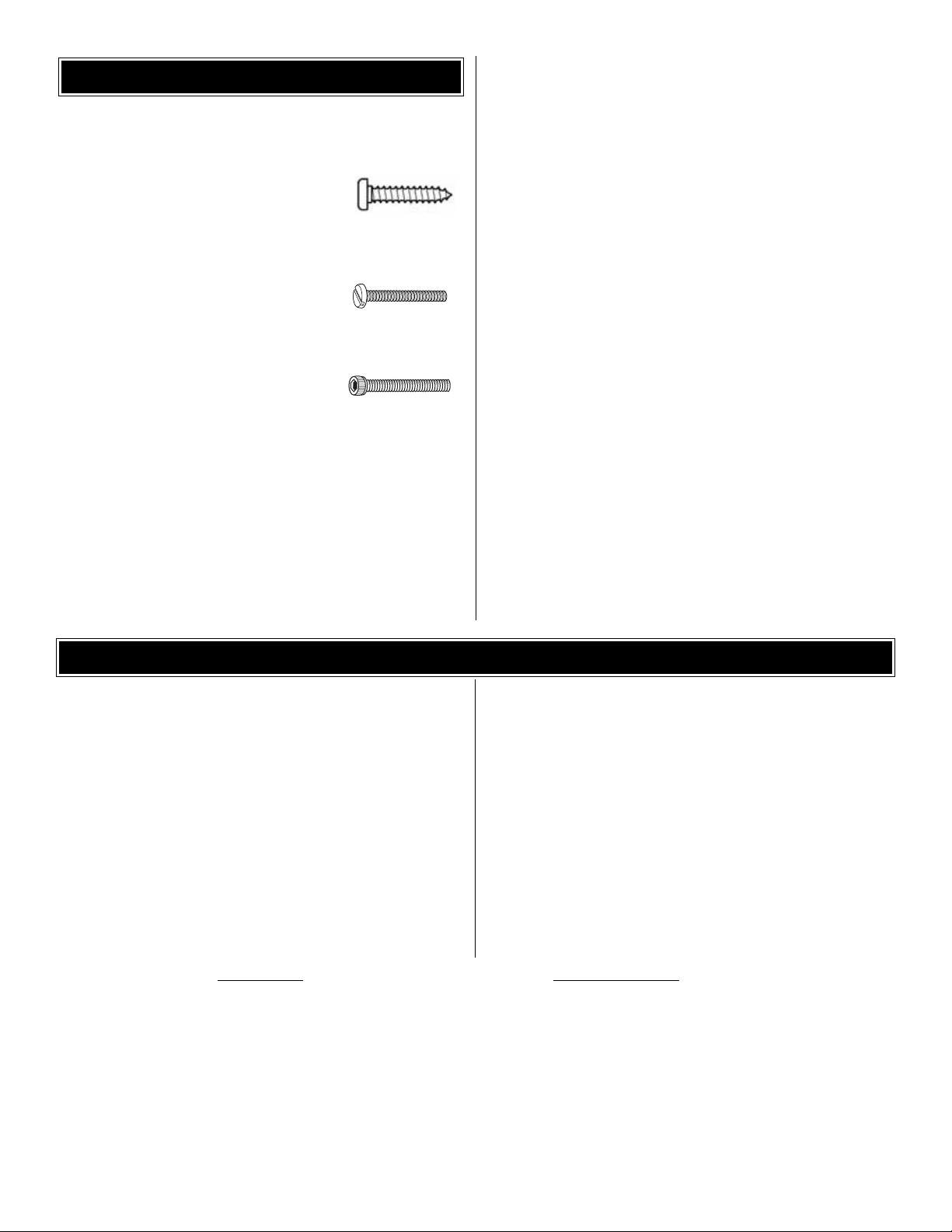
• There are two types of screws used in this kit:
Sheet metal screws are designated by a number and a
length. For example #6 x 3/4" [19 mm]
This is a number six screw that is 3/4" [19
mm] long.
Machine screws are designated by a number, threads per
inch and a length. For example 4-40 x 3/4" [19 mm]
This is a number four screw that is 3/4"
[19 mm] long with forty threads per inch
.
Socket head cap screws (SHCS) are designated by a
number, threads per inch and a length.
This is a number four screw that is 3/4"
[19 mm] long with forty threads per inch
.
• When y ou see the term
test fit
in the instructions, it means
that you should first position the part on the assembly
without using any glue, then slightly modify or
custom fit
the part as necessar y for the best fit.
• Whenever the term
glue
is written you should rely upon
your experience to decide what type of glue to use.When
a specific type of adhesive works best for that step, the
instructions will make a recommendation.
• Whenever just
epoxy
is specified you may use
either
30-minute (or 45-minute) epoxy or6-minute epoxy. When
30-minute epoxy is specified it is highly recommended that
you use only 30-minute (or 45-minute) epoxy, because you
will need the working time and/or the additional strength.
• Photos and sketches are placed before the step they
refer to .Frequently you can study photos in following steps
to get another view of the same parts.
• The Great Planes CAP 232 ARF is factory-covered with Top
Flite MonoKote®film. Should repairs ever be required,
MonoKote can be patched with additional MonoKote
purchased separately. MonoKote is packaged in six-f oot rolls,
but some hobby shops also sell it by the foot. If only a small
piece of MonoKote is needed for a minor patch, perhaps a
fellow modeler would give you some. MonoKote is applied
with a model airplane covering iron, but in an emergency a
regular iron could be used. A roll of MonoKote includes full
instructions for application. Following are the colors used on
this model and order numbers for six foot rolls.
True Red (TOPQ0227) Metallic Charcoal (TOPQ0407)
Jet White (TOPQ0204) Metallic Blue (TOPQ0402)
• The stabilizer and wing incidences and engine thrust angles
have been factory-built into this model. However, some
technically-minded modelers may wish to check these
measurements anyway.T o view this inf ormation, visit the web
site at www.greatplanes.com and click on “Technical Data.”
Due to manufacturing tolerances which will have little or no
effect on the way your model will fly, please expect slight
deviations between your model and the published values.
IMPORTANT BUILDING NOTES
5
ORDERING REPLACEMENT PARTS
Replacement parts for the CAP 232 ARF are available using
the order numbers in the Replacement Parts List that
follows. The fastest, most economical service can be
provided by your hobby dealer or mail-order company. Parts
may also be ordered directly from Hobby Services, but full
retail prices and shipping and handling charges will apply.
Illinois and Nevada residents will also be charged sales tax.
To locate a hobby dealer, visit the Great Planes web site at
www.g reatplanes.com.Choose “Where to Buy”at the bottom of
the menu on the left side of the page. Follow the instructions
provided on the page to locate a U.S., Canadian or
International dealer. If a hobby shop is not available,
replacement parts may also be ordered from Tower Hobbies®at
www.towerhobbies.com, or by calling toll free (800) 637-6050,
or from Hobby Services by calling (217) 398-0007, or via
facsimile at (217) 398-7721. If ordering via fax, include a Visa
®
or MasterCard®number and expiration date for payment.
Mail parts orders and payments by personal check to:
Hobby Services
3002 N Apollo Drive, Suite 1
Champaign IL 61822
Be certain to specify the order number exactly as listed in
the
Replacement Parts List.
Payment by credit card or
personal check only; no C.O.D.
If additional assistance is required for any reason, contact the
appropriate Product Support by telephone at (217) 398-8970
or by e-mail at
productsupport@greatplanes.com
.
Description
How to Purchase
Missing pieces......................................................Contact Product Support
Instruction manual ................................................Contact Product Suppor t
Full-size plans......................................................Not available
Kit parts listed below............................................Hobby Supplier
Replacement Parts List
GPMA2861 .............Wing Set
GPMA2862 .............Fuselage Kit
GPMA2863 .............Tail Surface Set
GPMA2864 .............Cowl
GPMA2865 .............Canopy
GPMA2866 .............Landing Gear
GPMA2867 .............Wheel Pants
GPMA2868 .............Tailwheel Assembly
GPMA2869 .............Decal Sheet

6
1 Cowl
2 Fuselage
3 Fuel Tank Assembly
4 Wheel Pants (2)
5 Stabilizer and Elevators
6 Rudder
7 Engine Mount
8 3.5" Main Wheels (2)
9 Landing Gear Struts
10 Wing Joiner
11 Pull-Pull Cable
12 Tailwheel Assembly
13 Left Wing Panel with Aileron
14 Right Wing Panel with Aileron
Kit Contents (Photographed)
4-40 Steel Clevis Threaded (8)
Solder Clevis for .095 Wire (6)
2x3/16" Bolt-On Axle Shaft (2)
Brass Quick Connector (1)
4-40 Blind Nut (4)
4-40 Hex Nut (8)
6-32 Blind Nut (6)
8-32 Blind Nut (4)
1/4-20 Blind Nut (2)
Nylon 1/4-20 x 2" Bolt (2)
Nylon Clevis (1)
Heavy Duty Control Horn (6)
Quick Connector Retainer (1)
1/4" Clevis Retainer (13)
#2 x 3/8" Screw (4)
#4 x 1/2" Sheet Metal Screw (30)
6-32 x 1/4" Socket Head Bolt (4)
3/16" Wheel Collar (4)
#6 Flat Washer (6)
#4 Flat Washer (10)
#2 Flat Washer (12)
#8 Lock Washer (8)
#8 Flat Washer (8)
#6 Lock Washer (6)
.074 x 12" Wire Threaded One End (1)
.095 x 5.75" Wire Threaded One End (6)
4-40 x 1/4" Socket Head Cap Screw (1)
4-40 x 1/2" Socket Head Cap Screw (4)
6-32 x 1-1/4" Socket Head Cap Screw (6)
8-32 x 1-1/4" Socket Head Cap Screw (4)
8-32 x 1" Socket Head Cap Screw (4)
2-56 x3/8" Machine Screw (8)
Kit Contents (Not Photographed)
KIT CONTENTS
Before starting to build, take an inventory of this kit to make sure it is complete, and inspect the parts to make sure they
are of acceptable quality. If any parts are missing or are not of acceptable quality , or if y ou need assistance with assemb ly,
contact Great Planes Product Support. When repor ting defective or missing parts, use the part names exactly as they
are written in the Kit Contents list on this page.
Great Planes Product Support:
Telephone: (217) 398-8970, ext. 5
Fax: (217) 398-7721
E-mail:
airsupport@greatplanes.com
KIT INSPECTION
1
3
8
7
2
4
13
10
14
9
5
11
6
12
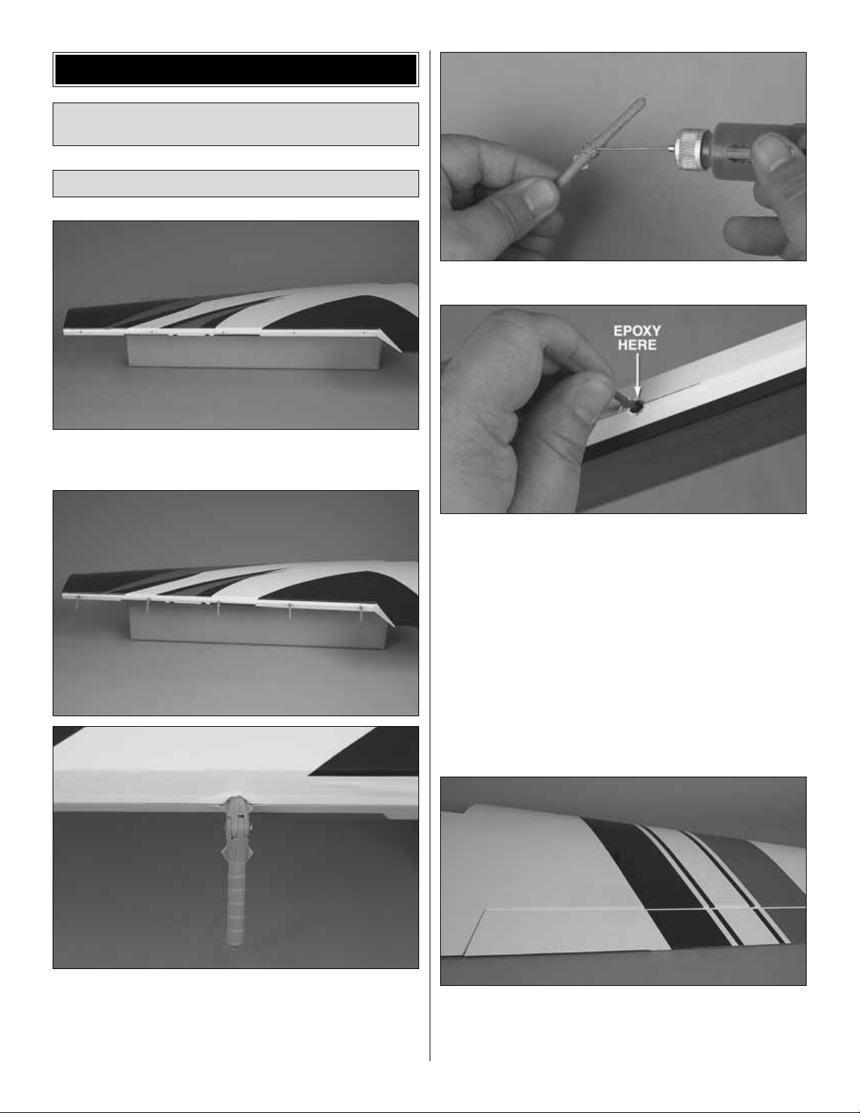
❏❏1.Cut the covering away from the fiv e predrilled holes
in the left aileron and left wing panel.
❏❏2. Locate five point hinges. Test fit each hinge by
temporarily attaching the aileron to the wing. Note the
“wings” on each hinge near the pivot.These are designed to
align the hinge and prevent it from rotating. It will take a
small amount of force to push these wings into the wood.
❏❏3.Apply a small drop of oil to the pivot on each hinge.
❏❏4. Mix approximately 1/8 oz of 30-minute epoxy. Use
a toothpick to thoroughlyapply the epoxy in the holes in the
aileron. Use the toothpick to get the epoxy out of the outer
edge of the opening of the holes in the aileron so it doesn’t
get into the hinge pins. Wipe away any epoxy around the
outside of the holes with a paper towel.
❏❏5. Push the point hinges into the holes in the aileron,
be sure to clean any epoxy squeezed out using alcohol and a
paper towel.
❏❏6.Once the epoxy has cured, mix 30-minute epoxy and
use a toothpick to thoroughly apply the epoxy in the holes in
the wing.
❏❏7. Fit the hinges in the wing and aileron. Tape the
aileron to the wing and set aside until the epoxy has cured.
❏ 8. Repeat steps 1-4 for the other wing half.
Attach the Ailerons
Before beginning assembly on y our new Great Planes CAP
232, tighten all covering with an iron or heat gun if needed.
ASSEMBLE THE WING
7
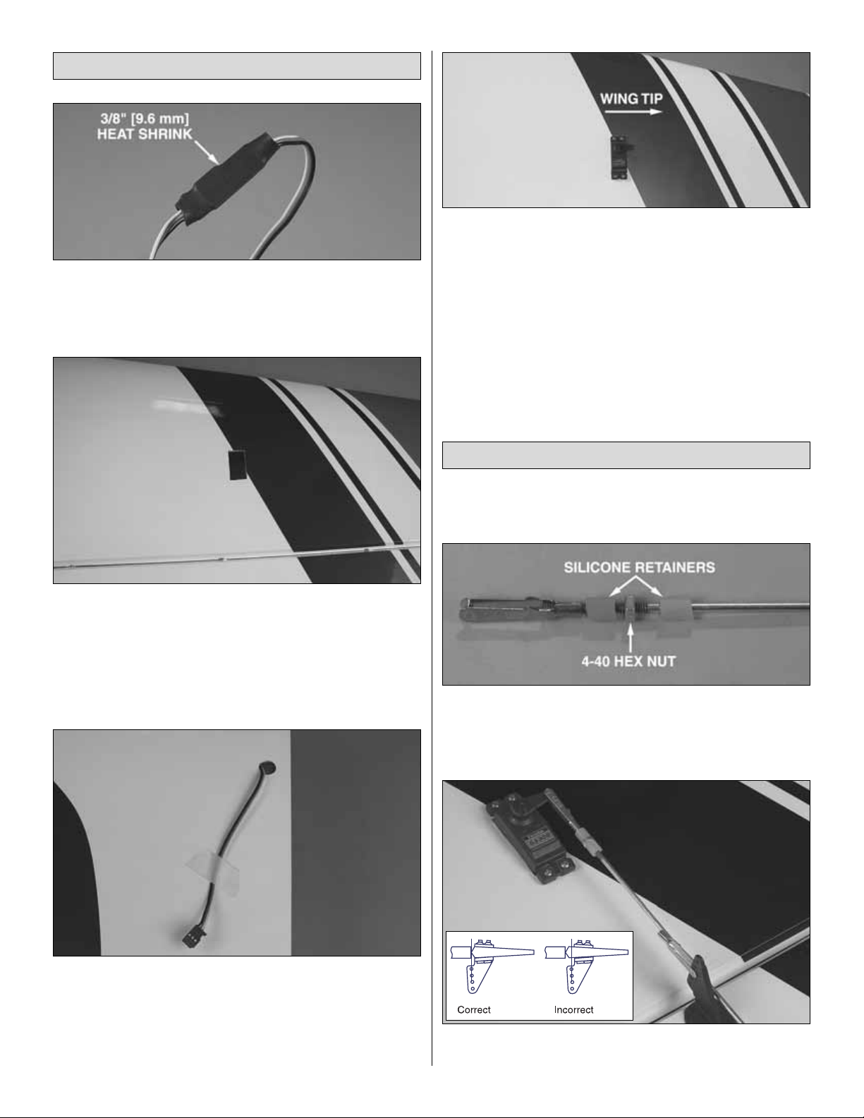
❏❏1.Connect a 12" [305 mm] servo extension to the aileron
servo and secure the connections with heat shrink tubing or
some other method such as tape or clamps designed to hold
servos together (not included).
❏❏2.Carefully remove the cov ering from the aileron servo
bay on the bottom of the wing using a sharp hobby knife .Seal
the covering down at the edge of the hole using an iron.
❏❏3.Locate the servo lead exit hole in the top of the wing.
Carefully remove the covering from this hole using a sharp
hobby knife.
❏❏4.Located in the wing in the aileron servo compartment,
a string is taped to the inside of the wing covering. Tie the
string to the end of the servo wire. Then pull the ser vo wire
through the wing with the string.Feed the servo wire out of the
hole in the top of the wing.Tape the servo wire to the wing to
prevent it from falling back into the opening.
❏❏5.Install the servo into the servo opening. Drill through
the servo mounting holes with a 1/16" [1.6 mm] drill bit.
Remove the servo from the servo opening. Install and then
remove a servo mounting screw into each of the holes you
have drilled.Apply a drop of thin CA into the holes to harden
the threads. Once the glue has hardened, install the servo
into the servo opening using the hardware included with your
servo.Center the servo , and then install a servo arm pointing
towards the wingtip.
❏ 6. Repeat steps 1-5 for the other wing panel.
❏❏1. Align the aileron at neutral and hold in place using
masking tape. Be sure the ser vo is centered.
❏❏2.Fit a silicone retainer, one 4-40 nut, another silicone
retainer and the clevis on the end of a 4-40 threaded one end
pushrod. Screw the clevis on 14 turns and temporarily
connect it to the aileron servo arm.
❏❏3. Attach one solder clevis to a black nylon control
horn and position it on the aileron as shown in the sketch
Connect the Ailerons
Install the Aileron Servos
8
and aligning it with the servo.Mark the location for the scre w
holes. Drill pilot holes in the marks you made with a 1/16"
[1.6 mm] drill bit, being careful not to drill through the
aileron.Secure the control horn to the aileron with four #4 x
1/2" [13 mm] screws.Remove the screws, harden the holes
with thin CA, and then reinstall the screws.
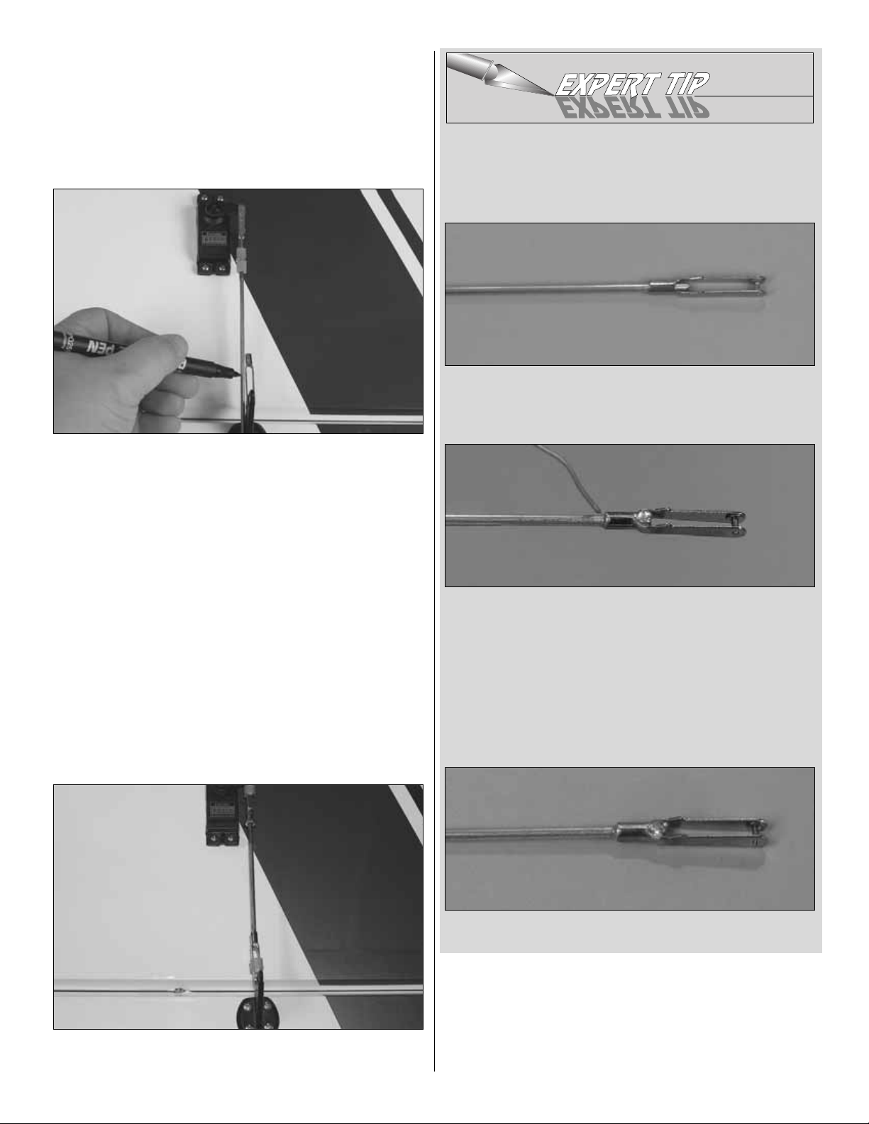
❏❏4.Align the pushrod with the clevis on the control horn
and make a mark using permanent marker or Panel Line
Pen where the pushrod extends 1/8" [3 mm] into the open
area of the clevis.Trim the 4-40 rod to length.
❏❏5. Remove the clevis and pushrod assembly from the
servo and the solder clevis from the control horn.
❏❏6. Attach the solder clevis to the pushrod using the
expert tip at the end of this section.
❏❏7. Reattach the pushrod assembly as shown. Be sure
to slide the silicone retainers over the clevises.
HOW T O SOLDER
❏ A. Use denatured alcohol or other solvent to thoroughly
clean the pushrod. Use coarse sandpaper to roughen the
end of the pushrod where it is to be soldered.
❏ B. Apply a few drops of soldering flux to the end of the
pushrod. Position the clevis so that 1/8" of the pushrod
protrudes into the open area of the clevis.
❏ C.Simultaneously heat the clevis and pushrod.Apply silver
solder (GPMR8070) to the joint. The heat of the parts being
soldered should melt the solder, thus allowing it to flow.
❏ D.Immediately after the solder has solidified, but while it
is still hot, carefully use a cloth to quickly wipe off the flux
before it hardens. Important: After the joint cools, coat with
oil to prevent rust.Note: Do not use the acid flux that comes
with silver solder for electrical soldering.
❏ E.This is what a properly soldered clevis looks like;shiny
solder with good flow, no blobs, flux removed.
❏ 8. Repeat steps 1-7 for the other aileron servo.
9

❏ 1. Locate the wing joiner.Measure and mark the centerline
of the joiner.
❏ 2.Test fit the wing joiner in one half of the wing. Sand as
needed to allow the joiner to fit snug in the wing.Then slide
the other wing half onto the joiner.There should be no gap
between the wing halves when joined. Note the direction of
the joiner.The “V”of the joiner should be towards the bottom
of the wing.
❏ 3. When satisfied with the fit, separate the wing panels
and remove the joiner.Mix a large batch of epoxy, enough to
cover one half of the wing joiner and the inside of one wing
joiner pocket. Half of one epoxy mixing cup, or 1/2 oz of
epoxy should work fine.Coat half of the wing joiner and one
wing joiner pocket with epo xy and insert the joiner .Clean up
any epoxy that oozes out using a paper to wel and denatured
alcohol. Allow the epoxy to fully harden before proceeding.
❏ 4.Mix another large batch of 30-minute epoxy, 1 oz should
do. Coat the other half of the wing joiner, wing joiner pocket
and the two wing roots with 30-minute epoxy. Join the two
wing halves and hold them together with masking tape until
the epoxy has completely hardened. Clean up any excess
epoxy with alcohol and a paper towel.
❏ 5. Locate the two 3/8" [10 mm] x 2" [51 mm] wooden
wing dowels. Round the edges of the dowels. Test fit the
dowels into the holes in the forward center section of the
wing as shown. Approximately 5/8" [16 mm] of the dowel
should be sticking out of the wing.Glue in place using epoxy .
❏ 6. Locate the wing bolt holes in the aft center section of
the wing. Remove the covering from these holes on the top
and bottom of the wing using a sharp hobby knife.
Join the Wing
10

❏ 7. Locate the wing bolt plate.Remove the covering from
the holes in the plate using a sharp hobby knife.
❏ 8. Align the holes in the wing bolt plate with the holes in
the wing. Trace an outline around the wing bolt plate. Tr im
away the covering approximately 3/32" [2 mm] inside the
outline. Be careful not to cut into the balsa structure as this
could weaken the wing.
HOW TO CUT COVERING FROM BALSA
Use a soldering iron to cut the covering from the stab.The
tip of the soldering iron doesn’t have to be sharp, but a fine
tip does work best. Allow the iron to heat fully. Use a
straightedge to guide the soldering iron at a rate that will just
melt the covering and not burn into the wood.The hotter the
soldering iron, the faster it must travel to melt a fine cut.
❏ 9. Glue the wing bolt in place using medium CA. After the
plate is installed, run a bead of medium CA around the edges
of the plate to prevent fuel from soaking into the balsa.
❏ 1. Locate the stab mounting slots near the rear of the
fuse and remove the covering using a sharp hobby knife.
❏ 2. Attach the wing to the fuselage using the two 1/4-20
nylon bolts.
❏ 3. Test fit the stab into the opening in the back of the
fuselage. Stand back and look at the stab in relation to the
wing.The stab should be parallel with the wing. If not, sand
the stab saddle until the stab and wing are aligned.
Install the Stab and Elevators
ASSEMBLE THE FUSELAGE
11
AA
A = A
 Loading...