

Page 1
WARRANTY
Great Planes
®
Model Manufacturing Co. guarantees this kit to be free from defects in both material and workmanship at the date of
purchase. This warranty does not cover any component parts damaged by use or modification. In no case shall Great Planes’ liability
exceed the original cost of the purchased kit. Further, Great Planes reserves the right to change or modify this warranty without notice.
In that Great Planes has no control over the final assembly or material used for final assembly, no liability shall be assumed nor accepted
for any damage resulting from the use by the user of the final user-assembled product. By the act of using the user-assembled product,
the user accepts all resulting liability.
If the buyer is not prepared to accept the liability associated with the use of this product, the buyer is advised to return this kit
immediately in new and unused condition to the place of purchase.
READ THROUGH THIS MANUAL BEFORE STARTING
CONSTRUCTION. IT CONTAINS IMPORTANT
INSTRUCTIONS AND WARNINGS CONCERNING
THE ASSEMBLY AND USE OF THIS MODEL.
GPMZ0242 for GPMA1400/1405 V1.0 Entire Contents © Copyright 2002
1610 Interstate Drive Champaign, IL 61822
(217) 398-8970, Ext. 2
airsupport@greatplanes.com
INSTRUCTION MANUAL
Wingspan: 31-1/4 in [794mm]
Wing Area: 343 sq in [22.1 dm
2
]
Weight: 24 oz. [680g]
Wing Loading: 10.1 oz./sq. ft. [30.8g dm
2
]
Fuselage Length: 31-3/4 in [800mm]
Motor: Speed 400, 7.2 volt
™
Page 2
INTRODUCTION ..........................................................................2
PRECAUTIONS............................................................................2
ADDITIONAL ITEMS REQUIRED................................................3
Flight Equipment ......................................................................3
Building Supplies ......................................................................3
REPLACEMENT PARTS..............................................................3
PARTS LIST ................................................................................4
HARDWARE BAG CONTENTS ..................................................4
METRIC CONVERSIONS ............................................................4
IMPORTANT BUILDING NOTES ................................................5
ASSEMBLY ..................................................................................5
Battery Charging ......................................................................5
Assemble the Fuselage............................................................5
Join the Wing & Fuselage ........................................................6
Install the Ailerons ....................................................................7
Assemble the Canards ............................................................9
Install the Canopy ..................................................................11
Install the Receiver ................................................................11
Mount the Motor ....................................................................12
Final Assembly ......................................................................13
PREPARE THE MODEL FOR FLYING ......................................15
Set the Control Throws ..........................................................15
Balance the Model (C.G.) ......................................................16
Identify Your Model ................................................................16
Charge the Transmitter Batteries............................................16
Ground Inspection ..................................................................17
Range Check..........................................................................17
Performance Tips....................................................................17
Motor Safety Precautions ......................................................17
AMA SAFETY CODE (excerpts) ..............................................17
FIND A SAFE PLACE TO FLY ..................................................18
FLYING ......................................................................................18
Takeoff ....................................................................................18
Flight ......................................................................................18
Landing ..................................................................................19
FLIGHT LOG ..........................................................BACK COVER
Thank you for purchasing the Great Planes Firebat™Electric
ARF. The Firebat ARF is a lightweight, high performance
Park Flyer
that can be flown just about anywhere there is an
open area clear of obstacles. Since the Firebat ARF is
constructed mostly of molded plastic foam, it is durable and
does not require the application of film coverings used on
wood models. The performance of the Firebat ARF is very
good with the included motor, but it can be improved
dramatically with an optional high performance motor,
battery, and electronic BEC speed control.
1. Although the Firebat ARF is a light-weight, electricpowered model, just the same as any R/C plane, it should
still be flown with care. Even while gliding with the motor off
the Firebat ARF could possibly cause injury to yourself or
spectators and damage property.
2. You must assemble the Firebat ARF according to the
instructions. Modifications may reduce performance. In
cases where the instructions differ from the photos, the
written instructions are correct.
3. You must use an R/C radio system that is reliable and in
good condition. You must properly install all components so
that the model operates correctly on the ground and in
the air.
4. You must check the operation of the model before every
flight to insure that all equipment is operating and that the
model has remained structurally sound.
Remember: Take your time and follow the instructions
to end up with a well-built model that is straight
and true.
If you have not flown this type of model before, we
recommend that you get the assistance of an experienced
pilot in your R/C club for your first flights. If you’re not a
member of a club, your local hobby shop has information
about clubs in your area whose membership includes
experienced pilots.
In addition to joining an R/C club, we strongly recommend
you join the AMA (Academy of Model Aeronautics). AMA
membership is required to fly at AMA sanctioned clubs.
There are over 2,500 AMA chartered clubs across the
country. Among other benefits, the AMA provides insurance
to its members who fly at sanctioned sites and events.
Additionally, training programs and instructors are available
at AMA club sites to help you get started the right way.
Contact
the AMA at the address or toll-free phone number below:
Academy of Model Aeronautics
5151 East Memorial Drive
Muncie, IN 47302-9252
Tele. (800) 435-9262
Fax (765) 741-0057
Or via the Internet at: http://www.modelaircraft.org
We, as the kit manufacturer, provide you with a top quality
kit and instructions, but ultimately the quality and flyability
of your finished model depends on how you build it;
therefore, we cannot in any way guarantee the
performance of your completed model, and no
representations are expressed or implied as to the
performance or safety of your completed model.
PROTECT YOUR MODEL, YOURSELF
& OTHERS...FOLLOW THESE
IMPORTANT SAFETY PRECAUTIONS
INTRODUCTION
TABLE OF CONTENTS
2
Page 3
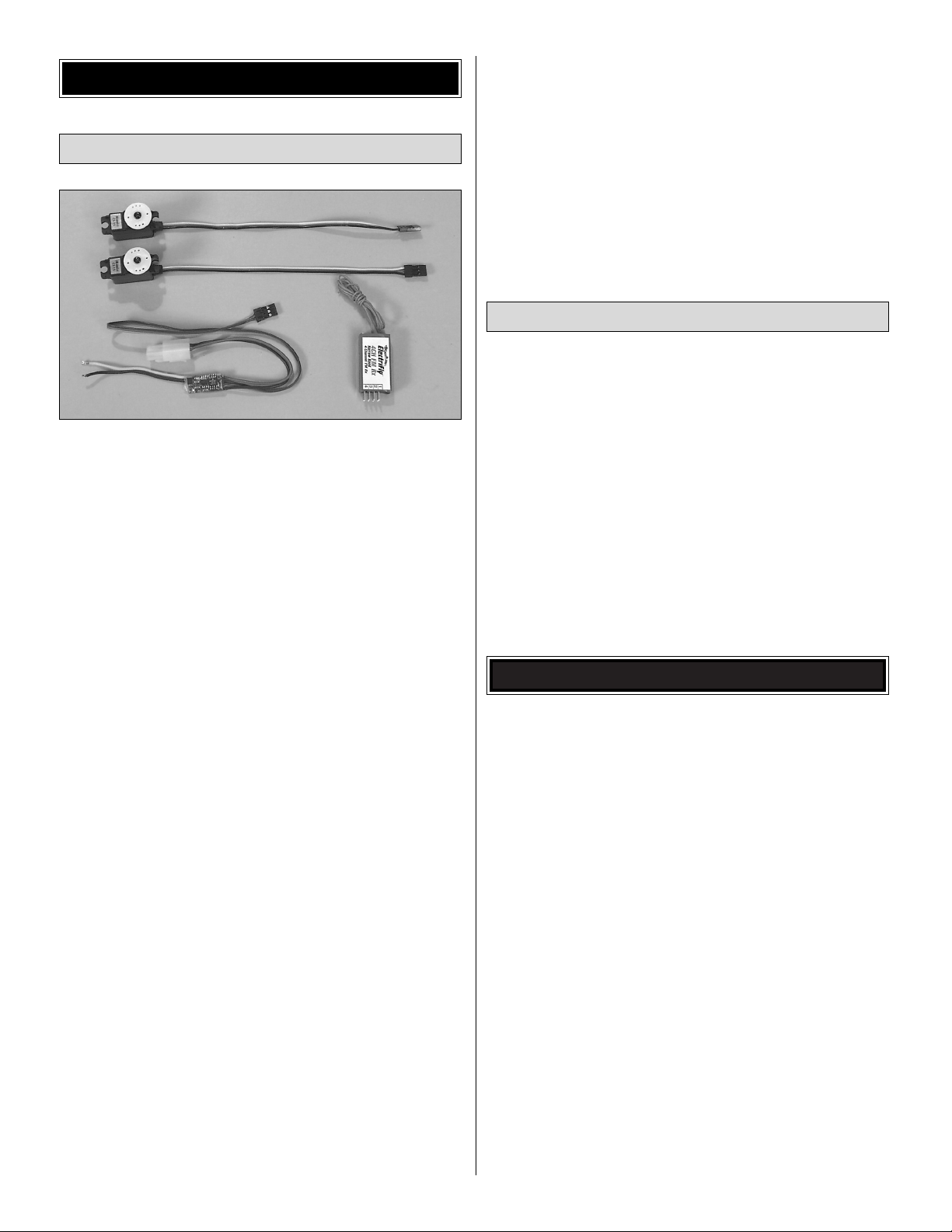
The Firebat ARF requires a three-channel radio with two
servos, a receiver and an electronic speed controller with
BEC. A full-size receiver and standard servos can be used.
You will
also need a 10" [254mm] (or 12" [305mm]) servo
extension
wire.
Flight performance and maneuverability can be improved
with dual aileron servos. You will need a mini servo for the
canard (elevator) with at least 30 oz. in. of torque and two
micro/mini servos for the ailerons with at least 15 oz. in. of
torque. You will also need a mini or micro receiver, a speed
controller and a 18" [457mm] (or 24" [610mm]) servo
extension
wire. This will require a four-channel radio system with
mixing functions.
Servos:
(HCAM0110) CS-12, 35 oz in torque
(FUTM0033) S3101, 34.7 oz in torque
(HRCM3401) HS-81J, 36 oz in torque
For dual aileron servos:
(HCAM0100) CS-15, 15 oz in torque
(FUTM0041) S3106, 16.7 oz in torque
(HRCM0981) HS-55J, 15 oz in torque
Mini Receivers:
(GPML0040) 4-channel FM, high band
(GPML0041) 4-channel FM, low band
(FUTL0407) 4-channel AM, low band
(FUTL0408) 4-channel AM, high band
(HRCL1535) 4-channel FM
low band - channels 11-35
high band - channels 36-60
Receiver crystal:
(FUTL62**) for GPM low band
(FUTL63**) for GPM high band
(FUTL47**) for FUT low band
(FUTL48**) for FUT high band
(HRCL23**) for HRC
** desired channel
Speed Control:
(GPMM2010) C-10, 12 amp
(GPMM2020) C-20, 20 amp
Servo Extension Wire:
(1) 10" (or 12") extension wire with standard receiver
(1) 18" (or 24") extension wire with micro receiver
Additionally, an 8-cell (9.6 volt) 600 to 1200 mAh battery
pack is required.
(GPMP0200) – 700 mAh NiCd
(GPMP0310) – 1100 mAh NiCd
In addition to common household tools, here is the list of
items used to build the Firebat ARF.
❏ 6-minute epoxy (GPMR6042)
❏ 1/2 oz. Thin CA+ (GPMR6001)
❏ Hobby knife (HCAR0105)
❏ #11 blades (HCAR0211)
❏ Drill and 1/16" drill bit
❏ Cellophane tape (for hinging ailerons)
❏ Double-sided foam tape (GPMQ4440) for mounting
receiver and speed control
❏ Sandpaper and sanding block
❏ Small phillips screwdriver (#1)
❏ Flat blade screwdriver
❏ Small T-pins (HCAR5100) or craft pins
If needed, replacement parts for your Firebat Electric ARF
are available through your hobby supplier. See the photo
and
“Parts List”
on page 4 for a reference of the parts
listed below.
(GPMG0330) Motor
(GPMQ1700) Propellers
(GPMA2372) Canard Set
(GPMA2373) Canopy
(GPMA2374) Rear Hatch
(GPMA2375) Vertical Fin Set
(GPMA2376) Fuselage Set
(GPMA2377) Hardware Pack
REPLACEMENT PARTS
Building Supplies
Flight Equipment
ADDITIONAL ITEMS REQUIRED
3
Page 4
4
1/64" = .4 mm
1/32" = .8 mm
1/16" = 1.6 mm
3/32" = 2.4 mm
1/8" = 3.2 mm
5/32" = 4.0 mm
3/16" = 4.8 mm
1/4" = 6.4 mm
3/8" = 9.5 mm
1/2" = 12.7 mm
5/8" = 15.9 mm
3/4" = 19.0 mm
1" = 25.4 mm
2" = 50.8 mm
3" = 76.2 mm
6" = 152.4 mm
12" = 304.8 mm
18" = 457.2 mm
21" = 533.4 mm
24" = 609.6 mm
30" = 762.0 mm
36" = 914.4 mm
Metric Conversions
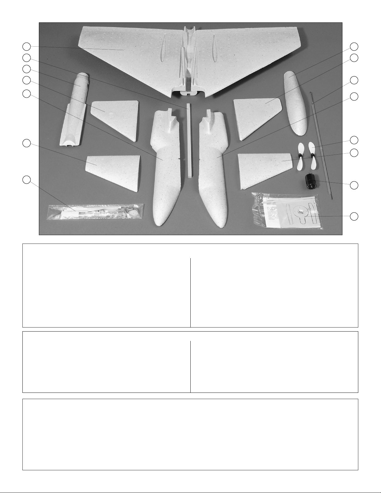
Parts-Standard Version
Key # Description Qty
1 MAIN WING .................................................................1
2 BALSA KEEL ...............................................................1
3 REAR HATCH..............................................................1
4 RIGHT VERTICAL FIN.................................................1
5 RIGHT FUSELAGE......................................................1
6 RIGHT CANARD..........................................................1
7 HARDWARE BAG........................................................1
8 CANOPY......................................................................1
9 LEFT VERTICAL FIN ...................................................1
10 PUSHRODS.................................................................2
Key # Description Qty
11 LEFT FUSELAGE ........................................................1
12 PROPELLERS .............................................................2
13 LEFT CANARD ............................................................1
14 MOTOR........................................................................1
15 MOTOR MOUNT PARTS BAG ....................................1
Parts-Deluxe Version (*not shown, includes all parts shown above plus the
following items)
* BATTERY.....................................................................1
* ELECTRONIC SPEED CONTROLLER (ESC) ............1
* 3-4 HOUR WALL CHARGER ......................................1
8
9
10
11
12
13
14
15
1
2
3
4
5
6
7
PARTS LIST
(3) 6" [152mm] HARDWOOD STICKS
(1) 2" [50mm] BALSA BLOCK
(1) 2" [50mm] NYLON BOLT
(2) NYLON WASHERS
(1) LONG NYLON CONTROL HORN
(2) SHORT NYLON CONTROL HORNS
(1) 5/8" [16mm] BRASS TUBE
(1) 1-3/16" [30mm] BRASS TUBE
(1) 6-1/4" [158mm] BRASS TUBE
(4) 2" [50mm] PUSHROD ENDS WITH Z-BENDS
(1) METAL HOOK
(1) 2 x 8mm SCREW
(4) RUBBER BANDS
(1) BAG (INCLUDES THE FOLLOWING)
(3) WHEEL COLLARS
(3) SET SCREWS
(1) ALLEN WRENCH
HARDWARE BAG CONTENTS
Page 5
• Since the Firebat ARF is made mostly of foam, and
since CA adhesives commonly used to build R/C model
airplanes dissolve foam, CA should not be used when
gluing foam parts. Therefore, 6-minute epoxy, which is
compatible with foam, is used for most of the
construction. Unless otherwise specified in the
instructions, 6-minute epoxy is to be used for gluing all
parts of the model together.
• For the strongest bond apply epoxy to both parts
being joined.
• Before beginning construction, refer to the parts
drawings and use a ballpoint pen to write the part
number on all the wood parts.
• During shipping some minor “scuffing” of the foam parts
may occur. This will not affect flight performance.
❏ 1. Now is a good time to charge the battery you will be
using. The Firebat Electric ARF builds very quickly so you
don't want do delay flying waiting for the battery to charge.
❏ 2. Make sure you have a fully run down battery before
charging.
❏ 3. Plug the battery charger into a standard 110 volt AC
wall outlet.
❏ 4. Connect the battery to the charger. Do not force the
plug; make sure that the plug is properly aligned.
❏ 5. Charge battery for 3-4 hours. A normal battery pack
will be warm when fully charged. WARNING: DO NOT
OVERCHARGE. IF THE BATTERY BECOMES HOT
DURING CHARGING, DISCONNECT FROM THE
CHARGER IMMEDIATELY AND ALLOW IT TO COOL
BEFORE USE. FAILURE TO DO SO MAY CAUSE THE
BATTERY TO LEAK OR EXPLODE, RESULTING IN
POSSIBLE INJURY OR BODILY HARM. Recharging a hot
battery will also decrease performance and battery life.
Note: The charger has an output of 300 mA. To determine
the charge time for other batteries, divide the battery
capacity by the charger output to get the charge time (i.e.,
1200 mAh divided by 300 mA = 4 hours). The Firebat Electric
ARF is so much fun to fly you should also consider obtaining
an additional battery or two and a field charger. Allow at
least 20 minutes of cooling time for the motor and battery
between flights.
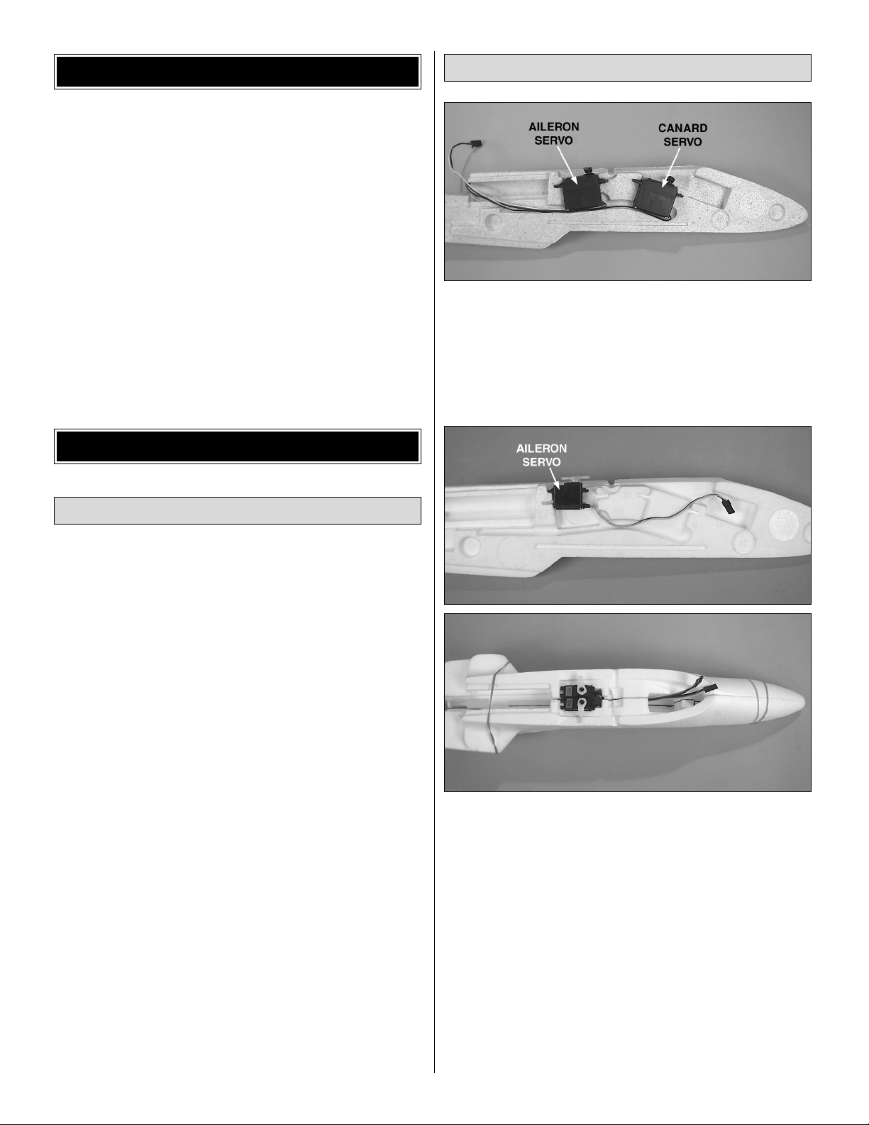
❏ 1. If you are using standard sized servos, position them
in the two recesses in the left fuselage side as shown in the
above photo. Be sure that the servo leads are in the premolded channels. The receiver will be installed behind the
servos later.
❏ 2. If you are using two mini or micro sized aileron servos
and a mini/micro receiver, position one of the servos in the
rear recess in the left fuselage side as shown in the above
photo A. Mark the location of the servo on the fuselage with
a fine-point felt-tip marker. Trim the fuselage side so the
servo will be recessed flush with the inside edge of the
fuselage side. Do the same for the right fuselage side. Be
sure that the servo leads are in the pre-molded channels.
Test fit the fuselage sides together to check the servo fit but
do not glue the sides at this time. The mini/micro receiver
will be installed in front of the servos later.
Note: When the sides are glued together the servos will be
installed side by side.
Assemble the Fuselage
Battery Charging
ASSEMBLY
IMPORTANT BUILDING NOTES
5
A
B
Page 6
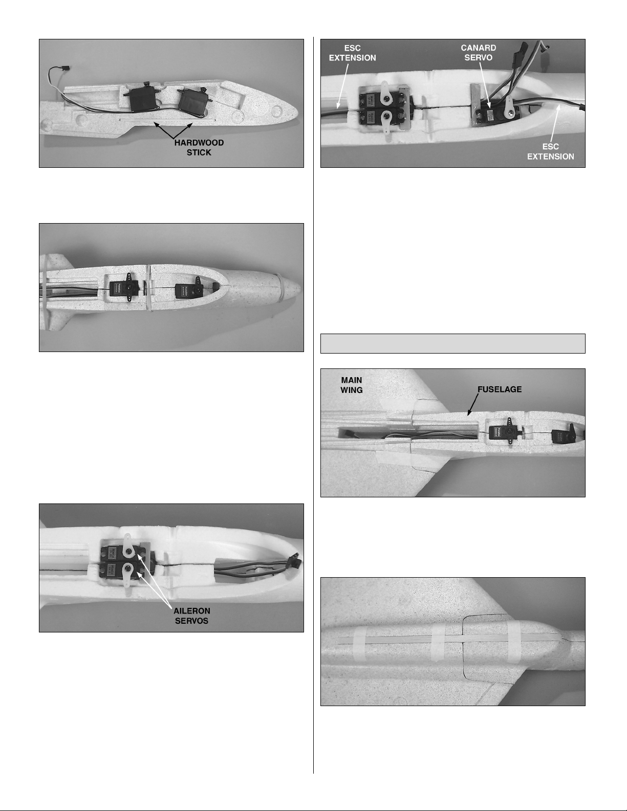
❏ 3. The 5/32" x 5/32" x 6" [4 x 4 x 152mm] hardwood stick
will be glued into the molded channel below the servos in
the next step.
❏ 4. Glue the fuselage sides together with 6-minute epoxy.
If you are using standard servos, be sure the servos are
properly positioned in the recesses and the leads are in the
channels. If you are using mini or micro servos, they will be
installed later. Be sure the stick is in its channel. Use tape or
rubber bands to hold the sides together until the epoxy
cures.
Note: To save weight you do not need to apply epoxy to the
entire mating surface. Make sure the edges and hardwood
stick are securely glued. Do not use so much epoxy that it
squeezes into the area of the servos and their leads.
❏ 5. If you are using a single aileron servo, continue with
“Join the Wing and Fuselage.”
If you are using two mini or
micro servos for the ailerons, install them in the cutouts you
made earlier, routing the leads in the channel below the
servos. Cut a 1/4" x 1-1/2" [6.4 x 38mm] piece from some
scrap 1/16" [1.6mm] ply (not included) and glue it to the
fuselage at the front of the servos. The screws supplied with
the servos or a dab of epoxy can be used to hold the servos
in place. See page 9, step 12 for another photo. Note: If you
want to hold the servos in place with screws, glue a piece of
ply at the front and rear of the servos.
❏ 6. Install a servo lead extension that will connect the
electronic speed control (ESC) to the receiver in the channel
under the two aileron servos. This lead must be at least 18"
long. Install the canard (elevator) servo in the cutout in front
of the aileron servos. Use a piece of scrap ply at the front
and rear of the servo.
❏ 1. Use 6-minute epoxy to glue the fuselage and main
wing together. Use tape to hold the parts together as the
epoxy hardens, ensuring that gaps between the parts are
kept to a minimum. Be careful not to get any epoxy in the
servo plugs.
❏ 2. Check the fit of the 3/8" x 3/8" x 12-3/4" [9.5 x 9.5 x
324mm] balsa keel in its slot in the bottom of the fuselage.
Round the front of the keel with sandpaper to match the
contour of the fuselage. Glue the keel into position in the
slot. Use tape to hold it in place until the epoxy cures.
Join the Wing & Fuselage
6
Page 7

❏ 1. There are two molded slots in the fuselage for the
aileron pushrod tubes. Lightly sand the tubes with medium
grit sandpaper. Cut 1" [25.4mm] from the end of each tube.
Save the cut off pieces for use later. Use epoxy to glue the
tubes in the slots. Use tape to keep the tubes firmly seated
in the slots until the epoxy hardens.
Note: To save weight, spot glue the tubes in the slots at five
or six locations instead of filling the slots up completely
with epoxy.
❏ 2. Make the aileron torque rods by pressing a nylon
control horn on one end of each 5/32" x 5/32" x 6" [4 x 4 x
152mm] hardwood stick. If the control horns are loose,
secure them with a drop of CA glue or some epoxy. Be sure
to make a left and right torque rod as shown in the photo.
❏ 3. Make a hole in each aileron to allow the control horn
to come through from below the aileron. The hardwood stick
should seat squarely in the groove in the bottom of the
aileron. Trim the hardwood stick to length if needed. The
hardwood stick will seat better in the groove if the corner of
the stick is rounded slightly with some sandpaper.
❏ 4. Glue the torque rods into place with 6-minute epoxy.
Make sure the control horns are vertical as shown in the
photo. Do not use a lot of epoxy and fill the groove. Use only
enough to hold the torque rods in place.
Install the Ailerons
7
Page 8

❏ 5. Cut the ailerons from the wing along the molded in cut
lines using a hobby knife with a fresh sharp blade. Using
several strokes instead of one deep cut will make a cleaner
cut. After they are cut apart, use some fine grit sandpaper to
smooth the back of the wing and the front of each aileron.
Note: The tips of the ailerons are easily damaged, so be
careful when cutting the ailerons from the wing. If you
damage the tips, or if the tips were damaged in shipping,
you can round or taper the tips at an angle. If you taper one
wing tip, make sure you taper the other the same way. This
will not affect the flying qualities of the model. If a large
section is broken, glue it together with some epoxy.
❏ 6. Enlarge the holes in both aileron control horns with a
1/16" [1.6mm] drill bit. Test fit the end of the aileron pushrod
in each hole and enlarge the hole if needed. Use the Z-bend
end of the pushrod. As long as you have the drill out, do the
same for the elevator control horn as well.
❏❏7. Cut a length of cellophane adhesive hinge tape the
length of the aileron. Stick the tape to the right aileron along
the leading edge so that it is even with the bottom of the
aileron. Press the tape down firmly into place. Fold the tape
back over itself
so that it will be easier to place it on the wing.
The tape in
the
above photo has been darkened so that it can
be easily
seen. Note: The aileron will be attached to the
wing in step 9.
❏❏8. Put a small bend 1-3/8" [35mm] from the end of a
long aileron pushrod, on the end with the Z-bend. If the
Z-bend does not have clean 90° bends, use a needle nose
pliers to adjust the bends. Connect the Z-bend end of the
pushrod to the top hole (middle hole if using two aileron
servos), of the control horn and then insert the pushrod into
the pushrod tube in the wing. Note: We are using two
servos
so, connect the Z-bend to the middle hole.
❏❏9. Position the aileron onto the wing. You will not be
able to hold it in position for the entire length, so hold one
section at a time. Press the tape firmly into place on the
wing.
❏❏10. Cut another length of adhesive hinge tape the
length of the aileron. Stick the tape to the top of the right
8
Page 9

aileron, but not onto the top of the wing. Deflect the aileron
down while holding it in position against the wing. One
section at a time, press the tape onto the top of the wing.
❏ 11. Return to step 7 and install the left aileron using the
same procedure.
❏ 12. To complete the aileron linkage installation, insert the
Z-bend end of two short pushrod ends into the servo arm,
from below the arm. For now, insert the ends in the inner
most hole of the servo arm. Center the servo arm and
secure the servo arm to the servo with its screw. Using two
wheel collars and set screws join the short pushrod ends to
the aileron pushrods. Center the servo arm as shown and
hold each aileron centered as each set screw is tightened.
Note: The bottom photo shows the installation of two
mini-servos.
❏ 1. Glue the brass bearing tubes in place with 6-minute
epoxy. The longer bearing tube is glued to the right side of
the fuselage. The tubes should project about 1/32" [1 mm]
past the sides of the fuselage. Use the long canard joiner
tube to align the bearing tubes as the epoxy hardens. Be
very careful not to get any epoxy on the joiner tube. Hint:
Use a little vaseline on the tube.
Note: The bearing tubes must be glued firmly into place, as
they will be subjected to high loads in flight.
❏ 2. Glue the long brass canard joiner tube into the slot in
the bottom of the left canard with 6-minute epoxy. After the
epoxy hardens, slide a nylon washer onto the brass tube
against the canard. Make sure the brass joiner tube is fully
sealed in the slot in the canard.
❏ 3. Slide the long joiner tube through the short bearing
tube on the left side of the fuselage. Install the 2 x 8mm
screw
Assemble the Canards
9
Page 10

onto the elevator horn. Slide the canard (elevator) horn onto
the joiner tube, oriented as shown in the photo. Continue to
slide the joiner tube through the second bearing tube.
❏ 4. Slide the other nylon washer onto the joiner tube.
When
the right canard is glued into place, it will be aligned as
shown in this photo and as shown in the photo for step 5
below. The rear edges of the canards should be in line with
each other.
❏ 5. Glue the right canard to the joiner tube with 6-minute
epoxy, making sure the nylon washer is still in place. Be
careful not to get any epoxy into the bearing tube. A drop of
light machine oil in the bearing tube will help prevent epoxy
from entering the tube. Use a straightedge to keep both
canards aligned as shown in the above two photos.
Note: For optimal flight performance it is very important that
both canards be accurately aligned and move freely in the
bearings.
❏ 6. Connect one of the short pushrod wires with a Z-bend
to the elevator horn in the second hole from the center.
Connect another short pushrod wire to the servo arm, also
in the second hole from the center. Insert the wire in the
servo arm from below as shown in the photo. Use a wheel
collar and set screw to join the two wires.
❏ 7. The canards are neutral when their trailing edges are
1mm above the canopy line. Use a straightedge to hold
them in this position. With the servo arm centered and
perpendicular to the servo and the control horn
perpendicular to the pushrod, tighten the set screw in the
wheel collar. Also tighten the screw in the control horn onto
the joiner tube.
10
Page 11

❏ 1. Cut a 3/4" [19mm] piece from the 3/8" x 3/8" [9.5 x
9.5mm] balsa stick. Screw the metal hook into the center of
this piece. Use a drop of CA to harden the balsa. The rubber
bands and nylon screw are used to hold the canopy to
the model.
❏ 2. Position the hook assembly 6-1/4" [160mm] from the
rear of the canopy. Glue it in place with 6-minute
epoxy.
❏ 3. Hook both rubber bands over the nylon bolt. Slide the
nylon bolt into the channel in the fuselage just aft of the
aileron
servo. Make sure the bolt is above the servo wires as
shown.
❏ 4. Attach the other end of the rubber bands to the hook
on the canopy. The rubber bands will pull the canopy down
onto the fuselage and back onto the hatch, which will be
installed later. Note: If you installed two aileron servos, you
may need to
trim the inside edge of the canopy slightly to
clear the
servos.
❏ 5. Remove the canopy and set it aside until later. If the
elevator control horn contacts the top of the canopy, cut the
top hole from the horn and round the corners.
❏ 1. Drill a 1/16" [1.6mm] hole on the lower left side of the
fuselage 3/4" [19mm] aft of the leading edge of the wing.
❏ 2. Cut a shallow channel in the wing fairing from the hole
you just made to the antenna channel molded into the
bottom of the left wing using a sharp knife.
Install the Receiver
Install the Canopy
11
Page 12

❏ 3. If you are installing a small receiver forward of the
servos go to step 4. Plug the servos and speed control into
the receiver. Route the receiver antenna into the hole you
made and pull it out of the hole as you install the receiver
into the model. If the receiver is not a snug fit, pad it with
some foam rubber. If it is a very tight fit, you can trim the
foam slightly. Continue with step 5.
❏ 4. If you are installing a small receiver forward of the
servos, plug the servos and speed control into the receiver.
Remove the arm from the elevator servo and slide the
receiver into the opening forward of the servo. If the opening
is not big enough, trim some of the foam from the edges.
The top photo shows the receiver partially inserted in the
opening. When the receiver is in place, reinstall the arm on
the elevator servo. Route the receiver antenna to the hole
you made earlier in the side of the fuselage.
❏ 5. Secure the antenna in its channel with adhesive tape
to cover it. Make sure that the full length of the antenna is
extended and that none of it remains inside the fuselage.
The motor supplied with the Firebat ARF has capacitors
internally installed in the motor and is shown being installed
in the following steps. There are many other higher
performance motors that can also be installed and we have
included a couple of photos of these installations as well.
One relatively low cost motor is the Kyosho®AP-29
(KYOG1929). These more powerful motors will not be able
to use the supplied prop (try an APC 5.5 x 4.5, APCQ4905).
In addition, they will require an adapter (GPMQ4600) to
mount the proper propeller and will also require a larger
capacity ESC.
❏ 1. Mount the motor to the 1/16" [2mm] ply motor mount
using the supplied 2.6 x 4mm screws.
❏ 2. Test fit the motor on the rear of the fuselage. Trim the
foam around the motor terminals as needed so that the
connectors from the speed control can be plugged onto the
terminals.
Mount the Motor
12
Page 13

Note: The motor is supplied with a flux ring installed. This
ring is present in the preceding photo and those that follow
and should be removed for the first flights. This ring will
increase flight time by reducing the current flow to the motor.
There is also a slight reduction in power.
❏ 3. Fit the 1/16" [2mm] ply reinforcement plates to the rear
of the fuselage. The plates are slightly oversize so that they
may be fitted to a variety of motors. Trim the plates as
needed to fit the shape of the fuselage.
❏ 4. Glue the reinforcement plates and the motor mount,
with the motor installed, into place with 6-minute epoxy.
The photo above shows the installation of a Kyosho AP-29
motor. As the motor is longer than the supplied motor, some
of the foam under the motor needs to be trimmed.
This photo shows the installation of a brushless motor and
speed control. Some trimming of the fuselage may be
needed, depending on the motor and speed controller.
This photo used for the next two steps.
❏ 1. Find one of the 1" [25.4mm] pieces that you cut from
the aileron pushrod and glue it to the groove in the rear
hatch. If you can’t find one, a tooth pick can be used.
Final Assembly
13
Page 14

❏ 2. Trim the rear of the hatch as needed to fit around the
ply motor reinforcement plates so that the hatch will fit flat
on the fuselage. You can see the area that was trimmed in
the previous photo. You will need to shave off material the
thickness of the ply. Note: Make sure the
pushrod tube “pin”
protrudes through the hole in the
plywood motor mount as
shown above.
❏ 3. When the canopy is installed, it will hold the front of the
hatch closed. For additional holding power, a Velcro type
fastener (GPMQ4480, not included) can be added at the
front of the hatch.
❏ 4. Connect the ESC to the motor. The positive terminal of
the motor is marked with a “+” sign, as well as a spot of red
paint on some motors. As the motor must rotate in reverse
(pusher), the negative wire from the ESC is connected to
the positive terminal of the motor. The negative wire is the
darker of the two wires. The ESC has plugs on the wires
which can be pressed onto the motor terminals, or the
connectors can be cut off and the wires soldered directly to
the motor terminals. Plug the ESC into the receiver.
Depending
on where your receiver will be located, you may need an
extension wire.
❏ 5. The completed motor/ESC installation, ready for the
battery.
❏ 6. Remove the screws from the servos holding the control
arms in place and remove the arms as well. Center the trims
on the transmitter and move the throttle stick to idle, then
turn on the transmitter. Connect a charged battery to the
ESC and turn it on according to the instructions supplied
with the ESC. With the controls in neutral, reinstall the servo
control arms and screws.
❏ 7. Locate the prop. Check that the lettering on the prop
will face aft when the prop is pressed onto the motor shaft.
If it does not, remove the rubber spinner mount and reverse
the direction of the prop, then press the rubber spinner
mount back onto the prop. Press the prop onto the motor
shaft 3/8" [9.5mm]. Make sure the prop is clear of any
obstacles. With the radio on, slowly advance the throttle and
make sure the prop turns in the proper direction. Remember
that this is a pusher type prop. If the rotation direction is not
correct, reverse the connectors on the motor. Disconnect
the battery and turn the radio off when finished.
Note: Some electronic speed controllers must be cycled
before they will turn on. Check the instructions that were
supplied with your ESC.
❏ 8. The Firebat ARF is balanced 4-1/2" [115mm] aft of the
leading edge of the wing, where it meets the fuselage. Make
a mark on both sides of the fuselage on the bottom of the
wing at this point.
14
Page 15

❏ 9. Also place a mark on the leading edge of the wing
6-7/8" [175mm] from the fuselage, on both sides of the
model. You can use any of these marked locations to
balance the model. Note: The model will be balanced after
the fins are installed.
❏ 10. Glue the fins to the top of the wing with 6-minute
epoxy. They may be glued on vertically or angled outwards
slightly, just be sure that both are at the same angle.
Note: Do not use an excessive amount of epoxy. Apply the
epoxy to the edges of the molded pockets and then press
the fins into place.
❏ 11. Apply the decals to the model as desired. Use the box
cover as a guide in applying any decals. You can also use
colored felt-tip permanent marking pens to paint areas of
the model without adding any weight. Water based paints
may be used as well.
IMPORTANT: Whenever connecting the battery always hold
onto the fuselage in case the motor accidentally receives
power and the propeller turns.
Note: Keep in mind that the canard is on the front of the
model, ahead of the C.G., not in the rear as is a normal
elevator. Therefore, the canard TE must deflect down to
obtain “up” elevator action.
❏ 1. Turn on the transmitter and connect the battery to the
speed control in the model. Be certain the ailerons, canards
and motor respond as shown in the chart. If required, use
the reversing function in the transmitter to reverse any
controls so they respond correctly.
❏ 2. Use the ATV function in the transmitter or adjust the
position of the pushrods on the servo arms or the control
horns on the canard (elevator) and ailerons to get the
control surface throws indicated in the chart on page 16.
The throws are measured at the widest part of the control
surface.
To increase the control surface throw, move the pushrod to
the hole that is closer-in on the control horn on the control
surface, or move the pushrod to the hole that is farther out
on the servo arm. To decrease the control surface throw, do
the opposite.
Note: Unless you are specifically checking the operation
of the motor, for safety remove the propeller from the
model while setting it up on your workbench.
Set the Control Throws
PREPARE THE MODEL FOR FLYING
15
Page 16

The C.G. (center of gravity) must be checked when the
model is ready to fly with the propeller and battery installed.
❏ 1. Use a felt-tip pen or narrow strips of tape to mark the
balance point on the bottom of the wing 4-1/2" [115mm]
from the leading edge of the wing on both sides of the
fuselage.
❏ 2. Lift the model, right side up, at the balance point you
marked on the bottom of the wing. If the nose drops the
model is nose-heavy and you must add weight to the tail. If
the tail drops, the model is tail-heavy and you must add
weight to the nose. In most cases you can relocate the
receiver and battery to achieve the correct balance without
adding additional weight. Our prototype models did not
require any weight to balance.
❏ 3. If additional weight is required to balanced the model,
use small pieces of Great Planes stick-on weight
(GPMQ4485).
If weight is required in the tail, it can be stuck to the top of
the wing next to the motor. If weight is required in the nose,
a slot can be cut in the nose where the weight can be
inserted. The slot can then be covered with tape.
❏ 4. After placing weight on the model where necessary,
recheck the C.G. to confirm that it is correct.
No matter if you fly at an AMA sanctioned R/C club site or if
you fly somewhere on your own, you should always have
your name, address, telephone number and AMA number
on or inside your model. It is required at all AMA R/C club
flying sites and AMA sanctioned flying events. Fill out the
identification tag on page 19 and place it on or inside
your model.
Be certain the transmitter batteries are fully charged. Follow
the battery charging instructions that came with your radio
control system to charge the batteries.
Charge the Transmitter Batteries
Identity Your Model
IMPORTANT: The C.G. (center of gravity), or balance
point has the greatest effect on how a model flies. Do not
overlook this important procedure. Modelers who do so
often find that the airplane is difficult to control, or out of
control after it is too late. Preserve your model and insure
that the first flight won’t be the last by balancing the model
according to the following instructions.
Balance the Model (C.G.)
Set up the Firebat ARF so it has the following control
surface throws:
CANARD (ELEVATOR):
(High Rate) 9/16" [15mm] up and down
(Low Rate) 3/8" [10mm] up and down
AILERONS:
(High Rate) 3/8" [10mm] up and down
(Low Rate) 5/16" [8mm] up and down
Second to the C.G., the control throws have the greatest
effect on the way a model flies. Set the throws as close to
these settings as possible. If you have too much control
throw the model may respond too quickly. If you do not
have enough throw you may not be able to maneuver the
model or have enough control to land it when the motor
is off.
16
Page 17

Before you fly you should perform one last overall inspection
to make sure the model is truly ready to fly and that you
haven’t overlooked anything. If you are not thoroughly
familiar with the operation of R/C models, ask an
experienced modeler to perform the inspection. Check to
see that you have the radio installed correctly and that all
the controls are connected properly. The motor must also be
checked by confirming that the prop is rotating in the correct
direction and the motor sounds like it is reaching full power.
Make certain the ailerons and canards are secure, the
pushrods are connected, the controls respond in the correct
direction, radio components are securely mounted, and the
C.G. is correct.
Ground check the operational range of your radio before the
first flight of the day. With the transmitter antenna collapsed
and the receiver and transmitter on, you should be able to
walk at least 100 feet away from the model and still have
control. Have an assistant stand by your model and, while
you work the controls, tell you what the control surfaces are
doing. Repeat this test with the motor running at various
speeds with an assistant holding the model, using hand
signals to show you what is happening. If the control
surfaces do not respond correctly, do not fly! Find and
correct the problem first. Look for loose servo connections
or broken wires, corroded wires on old servo connectors,
poor solder joints in your battery pack or a defective cell, or
a damaged receiver crystal from a previous crash. Be
careful of the propeller when range checking.
• Use fine sandpaper to remove imperfections along the
edges of the propeller. For the best performance, use a
Top Flite Precision Magnetic Prop Balancer
™
(TOPQ5700) to balance the propellers (this is a
necessity on glow-powered engines, but less critical on
small electric models).
• Using multiple battery packs for successive flights may
cause the motor to become excessively hot, thus
causing damage. Allow the motor to cool for at least 20
minutes between flights.
Note: Failure to follow these safety precautions may result
in severe injury to yourself and others.
Get help from an experienced pilot when learning to operate
the motor.
Use safety glasses when running motors.
Do not run the motor in an area of loose gravel or sand; the
propeller may throw such material in your face or eyes.
Keep your face and body as well as all spectators away from
the path of the propeller as you start and run the motor.
Keep items such as these away from the prop: loose
clothing, shirt sleeves, ties, scarfs, long hair or loose objects
(pencils, screwdrivers) that may fall out of shirt or jacket
pockets into the prop.
The electric motor and motor battery used in the Firebat
ARF are very powerful and the spinning propeller has a lot
of momentum; therefore, if you touch the propeller while it is
spinning it may inflict severe injury. Respect the motor and
propeller for the damage they are capable of and take
whatever precautions are necessary to avoid injury. Always
disconnect and remove the motor battery until you are ready
to fly again and always make sure the switches are turned
off before connecting the battery.
Read and abide by the following Academy of Model
Aeronautics Official Safety Code:
GENERAL
1. I will not fly my model aircraft in competition or in the
presence of spectators until it has been proven to be
airworthy
by having been previously successfully flight tested.
2. I will not fly my model aircraft higher than approximately
400 feet within 3 miles of an airport without notifying the
airport operator. I will give right of way to and avoid flying in
the proximity of full-scale aircraft. Where necessary, an
observer shall be utilized to supervise flying to avoid having
models fly in the proximity of full-scale aircraft.
3. Where established, I will abide by the safety rules for the
flying site I use and I will not willfully and deliberately fly my
models in a careless, reckless and/or dangerous manner.
7. I will not fly my model unless it is identified with my name
and address or AMA number, on or in the model.
RADIO CONTROL
1. I will have completed a successful radio equipment
ground
check before the first flight of a new or repaired model.
2. I will not fly my model aircraft in the presence of
spectators until I become a qualified flyer, unless assisted
by an experienced helper.
3. I will perform my initial turn after takeoff away from the pit,
spectator and parking areas and I will not thereafter perform
maneuvers, flights of any sort or landing approaches over a
pit, spectator or parking area.
AMA SAFETY CODE (excerpts)
Motor Safety Precautions
Performance Tips
Range Check
Ground Inspection
17
Page 18

4. I will operate my model using only radio control
frequencies currently allowed by the Federal
Communications
Commission.
Though the Firebat ARF is a “Park Flyer,” the best place to
fly any model is at an AMA chartered club field. Club fields
are set up for R/C flying, making your outing safer and more
enjoyable. We recommend that you join the AMA and a local
club so you can have a safe place to fly and have insurance
to cover you in case of a flying accident. The AMA address
and telephone number are in the front of this manual.
If there is no club or R/C flying field in your area, find a
suitable site that is clear of trees, telephone poles, buildings,
towers, busy streets and other obstacles. Since you are not
flying at a sanctioned AMA site, be aware that there may be
others like yourself who could be flying nearby. If both of
your models happen to be on the same frequency,
interference will likely cause one or both of the models to
crash. An acceptable minimum distance between flying
models is five miles, so keep this in mind when searching for
a flying site.
In addition to obstacles, it is important to be aware of people
who may wander into the area once you begin flying. At
AMA club flying sites it is a severe rule infraction to fly over
others, and this is a good practice if flying elsewhere. R/C
models tend to attract onlookers whose numbers can soon
multiply, forming small, uncontrolled crowds. Onlookers
pose two main problems. First is the danger of actually
crashing your model into a person, causing injury. Second is
the distraction from those who ask you questions while you
are trying to concentrate on flying. To minimize or avoid this
problem, have an assistant standing by who can spot
people who wander into your flying site (so you can avoid
flying over them) and who can perform “crowd control” if
people start to gather.
IMPORTANT: If you are an inexperienced modeler we
strongly urge you to seek the assistance of a competent,
experienced R/C pilot to check your model for airworthiness
AND to teach you how to fly. No matter how stable or
“forgiving” the Firebat ARF is, attempting to learn to fly on
your own is dangerous and may result in destruction of your
model or even injury to yourself and others. Therefore, find
an instructor and fly only under his or her guidance and
supervision until you have acquired the skills necessary for
safe and fully controlled operation of your model.
We recommend flying the Firebat ARF when the wind is no
greater than ten miles per hour. Less experienced flyers
should fly the Firebat ARF only in calm (less than one mile
per hour) conditions. Frequently, winds are calm in the early
morning and early evening. Often these are the most
enjoyable times to fly anyway!
Until you have the Firebat ARF properly trimmed for level
flight, we recommend having an assistant hand-launch the
model instead of launching it yourself.
Turn on the transmitter and plug the battery into the speed
control. Turn on the receiver by following the instructions that
came with your speed control.
IMPORTANT: Confirm that the transmitter operates the
controls by moving the sticks and watching the surfaces
respond. Occasionally, electric models have been launched
with the transmitter turned off or the battery disconnected
from the speed control!
When ready to launch, the assistant should hold the bottom
of the fuselage under the wing, then raise the model high
above his head and point it directly into the wind. With the
pilot (that would be you!) standing behind the plane, fully
advance the throttle to start the motor. As soon as the motor
is at full power, the hand launcher should gently toss the
plane into the air at a level or slightly nose-up attitude. Be
certain the model is being launched into the wind and be
immediately ready to make corrections to keep the airplane
flying straight, level and into the wind.
When the model has gained adequate flying speed under its
own power, gently pull the elevator stick back until the
airplane starts a gradual climb, then, reduce the back stick
pressure. Many beginners tend to pull too hard causing the
model to stall, so be gentle on the elevator and don’t panic.
If you do pull too hard and you notice the model losing
speed, release the elevator stick and allow the model to
regain airspeed.
Continue a gradual climb and establish a gentle turn (away
from yourself and any onlookers) until the airplane reaches
an altitude of 75 to 100 feet.
The Firebat ARF is typical of all delta wing aircraft in that
there is a great deal of drag when the flying speed is slow
and the nose of the aircraft is at a high angle of attack. The
Firebat ARF will climb much faster if you allow it to gain
some speed first and climb at a shallow angle.
The main purpose of the first few flights is to learn how the
model behaves and to adjust the trims for level flight. After
the model has climbed to a safe altitude reduce the throttle
Flight
Takeoff
FLYING
FIND A SAFE PLACE TO FLY
18
Page 19

slightly to slow the model, yet maintain altitude. The Firebat
ARF should fly well and maintain adequate airspeed at
about 1/2 – 3/4 throttle.
Adjust the elevator trim so the model flies level at the throttle
setting you are using. Adjust the aileron trim to level the
wings. It may take a few minutes to get the trims adjusted,
but this should be your first priority once at a comfortable
altitude. Continue to fly around, executing turns and making
mental notes (or having your assistant take notes for you) of
what additional adjustments or C.G. changes may be
required
to fine tune the model so it flies the way you like.
Begin the landing approach by flying downwind at an
altitude of approximately 40 feet [12 meters]. When the
airplane is approximately 50 to 100 feet [15 to 30 meters]
past you, gradually reduce power and make the “final” 180°
turn
directly into the wind, aligning the airplane with the runway
or landing area. Do not dive the airplane, as it will pick up
too much speed. Instead, allow the airplane to establish a
gradual descent. Concentrate on keeping it heading into the
wind toward the runway. When the plane reaches an altitude
of about 3 feet [1 meter], reduce power some more and
gently and slowly apply a little “up elevator” to level the
plane, but be careful as too much up elevator will cause it to
stall. While holding a slight amount of up elevator the
airplane will slow and descend as it loses flying speed, thus
touching down on the runway.
Until you are able to accurately judge how far the Firebat
ARF can glide, it may be helpful to reserve some battery
power to run the motor so the plane can be flown back to the
runway. Be aware that after the speed controller has cut off
the power, most speed controllers will allow you to reduce
the throttle to idle and then advance the throttle to obtain a
brief burst of power.
Best of luck and happy flying!
Make a copy of this identification tag and place it on or
inside the model.
Landing
19
Page 20

BUILDING NOTES
Kit Purchased Date: _______________________
Where Purchased:_________________________
Date Construction Started: __________________
Date Construction Finished: _________________
Finished Weight: __________________________
Date of First Flight: ________________________
FLIGHT LOG
 Loading...