

Page 1
WARRANTY
Great Planes
®
Model Manufacturing Co. guarantees this kit to be free from defects in both material and workmanship at the date of
purchase.This warranty does not cover any component parts damaged by use or modification. In no case shall Great Planes’ liability
exceed the original cost of the purchased kit. Further, Great Planes reserves the right to change or modify this warranty without notice.
In that Great Planes has no control over the final assembly or material used for final assembly, no liability shall be assumed nor
accepted for any damage resulting from the use by the user of the final user-assemb led product.By the act of using the user-assembled
product, the user accepts all resulting liability.
If the buyer is not prepared to accept the liability associated with the use of this product, the buyer is advised to return this
kit immediately in new and unused condition to the place of purchase.
READ THROUGH THIS MANUAL BEFORE
STARTING CONSTRUCTION. IT CONTAINS
IMPORTANT WARNINGS AND INSTRUCTIONS
CONCERNING THE ASSEMBLY AND USE OF
THIS MODEL.
GPMZ1352 for GPMA1380 V1.1© Copyright 2001
1610 Interstate Drive Champaign, IL 61822
(217) 398-8970, Ext 2
airsupport@greatplanes.com
INSTRUCTION MANUAL
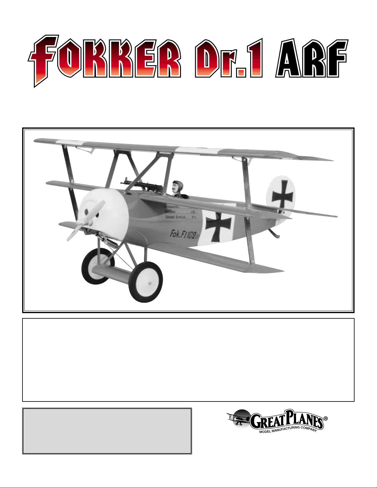
Top Wingspan: 60.25 in. [1530mm]
Middle: 51 in. [1295mm]
Bottom: 475 in. [1205mm]
Wing Area: 1367 sq. in. [88.2 sq dm]
Weight: 8.5 lbs [3865g]
Wing Loading: 14.3 oz./sq. ft. [43.8 g/sq dm]
Length: 49.63 in. [1260mm]
Radio: 4-Channel with 5 Servos
Engine: .46 to .60 two-stroke, .52 to .70 four-stroke [7.5 to 10cc two-stroke, 8.5 to 12cc four-stroke]
Page 2

INTRODUCTION ...............................................................2
SAFETY PRECAUTIONS..................................................2
ADDITIONAL ITEMS REQUIRED.....................................3
Muffler .........................................................................3
Hardware and Accessories .........................................3
Adhesives and Building Supplies................................3
Optional Supplies and Tools ........................................4
IMPORTANT BUILDING NOTES......................................4
KIT CONTENTS ................................................................5
ORDERING REPLACEMENT PARTS ..............................6
PREPARATIONS...............................................................7
BUILD THE FUSELAGE....................................................7
BUILD THE WINGS...........................................................8
Build the Bottom Wing.................................................8
Build the Mid Wing......................................................9
Build the Top Wing.....................................................10
INST ALLING THE WINGS ON THE FUSELAGE............14
INSTALLING THE STAB AND RUDDER........................15
ENGINE INSTALLATION ................................................17
RADIO INSTALLATION...................................................18
INST ALLING THE COWL................................................22
INSTALLING THE LANDING GEAR...............................23
FINAL ASSEMBLY..........................................................24
GET THE MODEL READY TO FLY.................................26
Check the Control Directions ....................................26
Set the Control Throws..............................................26
Balance the Model (C.G.)..........................................27
Balance the Model Laterally ......................................27
PREFLIGHT.....................................................................27
Identify Your Model....................................................27
Charge the Batteries .................................................27
Balance Propellers....................................................28
Ground Check...........................................................28
Range Check.............................................................28
ENGINE SAFETY PRECAUTIONS.................................28
AMA SAFETY CODE......................................................29
IMAA SAFETY CODE.....................................................29
CHECK LIST ...................................................................30
FLYING ............................................................................31
Fuel Mixture Adjustments..........................................31
Takeoff.......................................................................31
Flight..........................................................................32
Landing......................................................................32
ENGINE MOUNT TEMPLATE.........................................35
Thank you for purchasing the Great Planes F okk er Dr. I ARF.
The original Fokker Dr. I was designed in 1915 by Anthony
Fokker. He wanted an aircraft that could out-maneuver any
other fighter of the day and to do so he knew he needed
maximum lift with minimum weight. To accomplish this he
designed an airplane with three wings and an auxiliary fourth
wing on the landing gear with a total empty weight of 827 lb
(376 kg).Because of the sturdiness of the three-wing design,
flying wires were eliminated with the exception of the aileron
control wires that run from the fuselage up to the top wing.
The Fokker Dr. I could turn so sharply that if forced, it could
cause a blackout to the pilots at the controls. The rate of
climb was nearly 2,000 fpm (10.2 m/s) with a service ceiling
of 18,000 feet (5,487 m).Top speed was 97 mph (155 kph)
while stall speed was 30mph (48 kph).
Perhaps the most famous pilot to fly this aircraft was Manfred
Von Richthofen, otherwise known as the Red Baron. He
regularly flew at least four different triplanes and while all of
them had a dark red base color, they all had slightly different
trim schemes. The aircraft Great Planes chose to model was
the one with the serial number FI 102/17, which is the one the
Red Baron used when he was visiting other wings under his
command or when he was visiting the Fokker factory.
The full-size Fokker Dr. I had a total wingspan of 23 ft, 7 in
(7.2 m).The Great Planes model has a total wingspan of 601/4" (1524 mm).This wingspan makes this model eligible to
participate in IMAA events.The scale of the model is 1: 4.7.
For the latest technical updates or manual corrections for
the Great Planes Fokker Dr. I ARF, visit the web site listed
below and select the Great Planes Fokker Dr. I ARF. If there
is new technical information or changes to this kit, a “tech
notice” box will appear in the upper left corner of the page.
http://www.greatplanes.com/airplanes/index.html
1.Your Fokker Dr .I should not be considered a toy , b ut rather
a sophisticated, working model that functions very much like
a full-size airplane. Because of its performance capabilities,
the Fokker Dr. I, if not assembled and operated correctly,
could possibly cause injury to yourself or spectators and
damage to property.
2.You must assemble the model according to the instructions.
Do not alter or modify the model, as doing so may result in an
unsafe or unflyable model. In a few cases the instructions may
differ slightly from the photos. In those instances the written
instructions should be considered as correct.
PRO TECT YOUR MODEL,YOURSELF
& OTHERS...FOLLOW THESE
IMPORTANT SAFETY PRECAUTIONS
INTRODUCTIONTABLE OF CONTENTS
2
Page 3

3.You must take time to build straight, true and strong.
4. You must use an R/C radio system that is in first-class
condition, and a correctly sized engine and components
(fuel tank, wheels, etc.) throughout the building process.
5.You must correctly install all R/C and other components so
that the model operates correctly on the ground and in the air .
6.You must check the operation of the model before every
flight to insure that all equipment is operating and that the
model has remained structurally sound. Be sure to check
clevises or other connectors often and replace them if they
show any signs of wear or fatigue.
7. If you are not already an experienced R/C pilot, you
should fly the model only with the help of a competent,
experienced R/C pilot.
8. While this kit has been flight tested to exceed normal use,
if the plane will be used for extremely high stress flying, such
as dogfighting, the modeler is responsible for taking steps to
reinforce the high stress points.
Remember:T ake your time and f ollow the instructions to
end up with a well-built model that is straight and true.
If you have not flo wn this type of model before , we recommend
that you get the assistance of an experienced pilot in your R/C
club for your first flights.If you're not a member of a club, your
local hobby shop has information about clubs in your area
whose membership includes experienced pilots.
In addition to joining an R/C club, we strongly recommend
you join the AMA (Academy of Model Aeronautics). AMA
membership is required to fly at AMA sanctioned clubs.There
are over 2,500 AMA chartered clubs across the country.
Among other benefits, the AMA provides insurance to its
members who fly at sanctioned sites and events .Additionally,
training programs and instructors are available at AMA club
sites to help you get started the right way. Contact the AMA
at the address or toll-free phone number below:
Academy of Model Aeronautics
5151 East Memorial Drive
Muncie, IN 47302-9252
Tele. (800) 435-9262
Fax (765) 741-0057
Or via the Internet at:
http://www.modelaircraft.org
The Great Planes Fokker Dr. I ARF is an excellent sport-scale
model.Though it is not par ticularly large, its 60-1/4" wingspan
makes it eligible to fly in IMAA events.The IMAA (International
Miniature Aircraft Association) is an organization that promotes
non-competitive flying of giant-scale models. If you plan to
attend an IMAA event, contact the IMAA f or a copy of theIMAA
Safety Code at the address or telephone number below.
IMAA
205 S. Hilldale Road
Salina, KS 67401
(913) 823-5569
If you plan to use a 2-stroke .46 or .60 size engine, you will
need to use a Pitts style muffler.The B.C .M.(Bisson Custom
Mufflers) #04061 (BISG4061) Pitts muffler or the Slimline
#3217 (SLIG2217) Pitts Style will work well for the O.S. .61
SF, FP and FX. Use the B.C.M. # 04046 (BISG4046) or the
Slimline # 3218 (SLIG2218) for the O .S .46 SF of FX.To use
any of these mufflers, a portion of the included 60-120
engine mount may need to be trimmed.
This is the list of hardware and accessories required to finish the
Fokker Dr. I ARF. Order numbers are provided in parentheses.
❏ .46 to .60 2-stroke or .52 to .70 4-stroke
❏ 4-Channel radio with five servos (two aileron servos)
❏ Propeller (refer to engine manufacturer's recommendations)
❏ 3' Medium fuel tubing (GPMQ4131)
❏ Y-harness for dual aileron servos (HCAM2500 for Futaba
®
J)
❏ 12" Ser vo extension cord (HCAM2100)
❏ Two 6" Servo extension cords (HCAM2000)
❏ Switch and charge jack mounting set (GPMM1000)
In addition to common household tools and hobby tools, this
is the “short list” of the most important items required to
build the Fokker Dr. I ARF.
Great Planes Pro™CA and
Epoxy glue are recommended.
❏ 30-Minute Epoxy (GPMR6047)
❏ 1/2 oz. Thin Pro CA (GPMR6001)
❏ 1/2 oz. Medium Pro CA+ (GPMR6007)
❏ Hobby knife (HCAR0105)
❏ #11 blades (HCAR0211)
❏ Single-Edge razor blades (HCAR0212)
❏ Small T-pins (HCAR5100)
❏ Builder's triangle (HCAR0480)
Adhesives and Building Supplies
Hardware and Accessories
Muffler
ADDITIONAL ITEMS REQUIRED
We, as the kit manuf acturer, provide you with a top quality
kit and instructions, but ultimately the quality and flyability
of your finished model depends on how you build it;
therefore, we cannot in any way guarantee the
performance of your completed model and no
representations are expressed or implied as to the
performance or safety of your completed model.
3
Page 4
❏ Electric drill with 1/16" [1.6mm], 3/32" [2.4mm], 5/32"
[4mm], 7/32" [5.6mm] drill bits
❏ Small Phillips and flat blade screwdrivers
❏ Pliers with wire cutter (HCAR0630)
❏ Sealing Iron (TOPR2100)
❏ Curved Tip Canopy Scissors for trimming plastic parts
(HCAR0667)
❏ 220-Grit wet sandpaper
❏ Panel Line Pen (TOPQ2510)
❏ Trim Seal Tool (TOPR2200)
❏ Pacer Formula 560
™
Canopy Glue (PAAR3300)
❏ Small Metal File
❏ K & S #801 Kevlar thread (K+SR4575)
❏ Fuel Line Plug (GPMQ4166)
❏ Pro Thread Locking Compound (GPMR6060)
❏ Heat Shrink Tubing
❏ 8-32 Tap and Drill Set (GPMR8103)
Here is a list of optional tools mentioned in the manual that
will help you build the Fokker Dr. I ARF.
❏ Charge receptacle for aileron e xtension cord (ERNM3001)
❏ Hobbico
®
Servo Horn Drill (HCARo698)
❏ Top Flite
®
Precision Magnetic Prop Balancer™(TOPQ5700)
❏ Top Flite Hot Sock
™
iron cover (TOPR2175)
❏ Robar t Superstand II (ROBP1402)
❏ Straightedge with scale (HCAR0475)
❏ Cutting mat (HCAR0456)
❏ Masking T ape (TOPR8018)
❏ CA Debonder (GPMR6039)
❏ Williams Brothers Standard 1/5 Pilot (WBRQ2477)
❏ CA Applicator tips (GPMR6033 or HCAR3780)
❏ CA accelerator (GPMR6034)
❏ 6-Minute Epoxy (GPMR6045)
❏ Epoxy Brushes (GPMR8060)
❏ Mixing Sticks (GPMR8055)
❏ Denatured Alcohol (for epoxy clean up)
❏ Rotar y tool such as Dremel (for fiberglass cowl)
❏ Dead Center
™
Engine Mount Hole Locator (GPMR8130)
❏ Great Planes AccuThrow
™
Deflection Gauge (for
measuring control throws, GPMR2405)
❏ Aluminum LustreKote
®
(TOPR7205)
❏ Dark Red LustreKote
®
(TOPR0218)
❏ Devcon
™
Silicone glue (DEVR2500)
❏ Testors
™
1/2oz Flat Black (TESR2649)
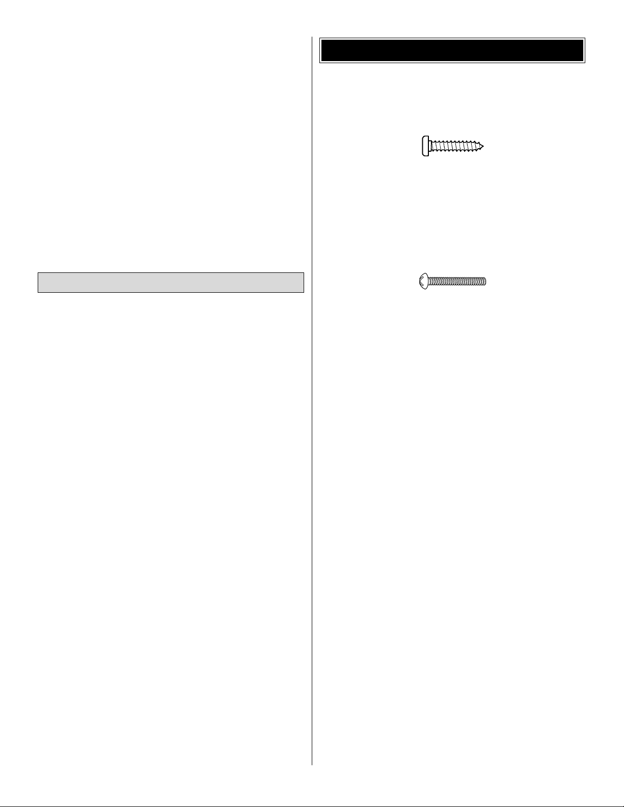
• There are two types of screws used in this kit:
Sheet metal screws are designated by a number and a
length. For example #6 x 3/4"
This is a number six screw that is 3/4" long.
Machine screws are designated by a number, threads per
inch and a length. (SHCS is just an abbreviation for “Socket
Head Cap Screw” and that is a michine screw with a socket
head.) For example 4-40 x 3/4"
This is a number four screw that is 3/4" long with
forty threads per inch.
• When you see the term
test fit
in the instructions, it
means that you should first position the part on the
assembly without using any glue, then slightly modify or
custom fit
the part as necessar y for the best fit.
• Whenever the term
glue
is written you should rely upon
your experience to decide what type of glue to use.When a
specific type of adhesive works best for that step, the
instructions will make a recommendation.
• Whenever just
epoxy
is specified you may use
either
30-minute (or 45-minute) epoxy or6-minute epoxy. When
30-minute epoxy is specified it is highly recommended that
you use only 30-minute (or 45-minute) epoxy, because you
will need the working time and/or the additional strength.
• Photos and sketches are placed before the step they
refer to. Frequently you can study photos in following steps
to get another view of the same parts.
• The Fokker Dr. I ARF is factory-covered with Top Flite
MonoKote®film. Should repairs ever be required, MonoKote
can be patched with additional MonoKote purchased
separately. MonoKote is packaged in six-foot rolls, but some
hobby shops also sell it by the foot. If only a small piece of
MonoKote is needed for a minor patch, perhaps a fellow
modeler would give you some. MonoKote is applied with a
model airplane covering iron, but in an emergency a regular
iron could be used. A roll of MonoKote includes full
instructions for application.Following are the colors used on
this model and order numbers for six-foot rolls.
True Red (TOPQ0227)
White (TOPQ0204)
Black (TOPQ0208)
IMPORTANT BUILDING NOTES
Optional Supplies and Tools
4
Page 5
5
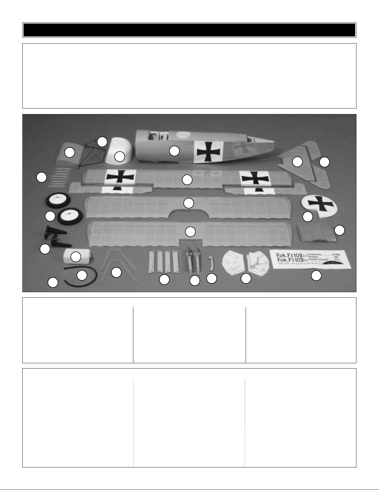
1 Fuselage
2 Fiberglass Cowl
3 Landing Gear
4 LG Wing
5 Elevators
6 Stabilizer
7 Ruddder
8 Mid Wing Cover
9 Decal Sheet
10 Top Wing with Ailerons
11 LG Fairings
12 Scale Wheels
13 Engine mount
14 Cockpit Coaming
15 Metal Step
16 Fuel T ank with Hardware
17 Metal Cabane
18 Mid Wing
19 Wood Struts
20 Tail Skid
21 Dummy Guns
22 Bottom Wing
23 Dummy Engine
(4) 1/4-20 x 2" [51 mm] Nylon wing bolts
(6) Silicone retainers
(5) Nylon large control horns
(6) Nylon clevis
(4) 8-32 Blind nuts
(4) 8-32 x 1" [25 mm] SHCS
(2) 6-32 x 1/4" [6.3 mm] SHCS
(4) 5/32" [4 mm] Wheel collars
(2) 6-32 SH set screws
(8) #8 Flat washers
(4) 2-56 x 1/2" [12 mm] SHCS
(6) 2-56 x 3/4" [19 mm] SHCS
(8) #4 Flat washers
(32) #2 x 3/8" [9.5 mm] Screws
(1) Screw-lock connector
(1) Nylon retainer for screw-lock connector
(1) 4-40 x 1/8" [3 mm] SHCS
(2) 2-56 x 6" [152 mm] Threaded one end
pushrods
(1) 2-56 x 17-1/2" [444 mm] Threaded one
end pushrod
(3) 2-56 x 36" [914 mm] Threaded one end
pushrods
(1) 11-3/4" [298 mm] Outer flexible pushrod
(12) #4 x 3/8" [9.5 mm] Screws
(4) #4 x 1/2" [12 mm] Screws
(8) #8 lock washers
(8) 4-40 x 1/4" [6.3 mm] SHCS
(4) 8-32 x 3/4" [19 mm] SHCS
(4) #2 Flat washers
(4) Faslinks
(8) 4-40 x 3/8" [9.5 mm] SHCS
(3) 5/32" [4 mm] Nylon landing gear straps
(8) Flat nylon landing gear straps
(2) Plywood aileron servo covers
(8) Hardwood blocks
(6) 60 degree, 1/16" [1.8mm] steel brackets
(10) 90 degree, 1/16" [1.8mm] steel brackets
(1) 2" x 9" CA hinge material
Kit Contents (Photographed)
Kit Contents (Not Photographed)
Before starting to build, use the Kit Contents list to take an inventory of your kit to make sure it is complete and inspect
the parts to make sure they are of acceptable quality. If any parts are missing or are not of acceptable quality, or if you
need assistance with assembly, contact Great Planes Product Support. When reporting defective or missing parts, use
the part names exactly as they are written in the Kit Contents list on this page.
Great Planes Product Support:
Phone: (217) 398-8970
Fax: (217) 398-7721
E-mail: airsupport@greatplanes.com
KIT CONTENTS
3
4
2
1
6
5
11
12
13
15
16
14
17
10
18
22
19
21
20
23
7
8
9
Page 6
6
To order replacement parts for the Great Planes Fokker Dr. I ARF, use the order numbers in the Replacement Parts List
that follows. Replacement par ts are available only as listed. Not all parts are available separately (an aileron cannot be
purchased separately, but is only available with the wing kit).Replacement par ts are not available from Product Support,
but can be purchased from hobby shops or mail order/Internet order firms. Hardware items (screws, nuts, bolts) are also
available from these outlets. If you need assistance locating a dealer to purchase par ts, visit www.greatplanes.com and
click on “Where to Buy.” If this kit is missing parts, contact Great Planes Product Support.
Replacement Parts List
Order Number Description How to Purchase
Missing pieces ......................Contact Product Support
Instruction manual.................Contact Product Suppor t
Full-size plans.......................Not available
GPMA2240......................................Top Wing Kit
GPMA2241......................................Mid Wing Kit
GPMA2242......................................Bottom Wing Kit
GPMA2243......................................Fuselage Kit
GPMA2244......................................Tail Set
GPMA2245......................................Cowl
GPMA2246......................................Landing Gear
GPMA2247......................................Wheels
GPMA2238......................................Mid Wing Cover w/ Guns
GPMA2239......................................Strut Set
ORDERING REPLACEMENT PARTS
....
Contact Your Hobby
Supplier to Purchase
These Items
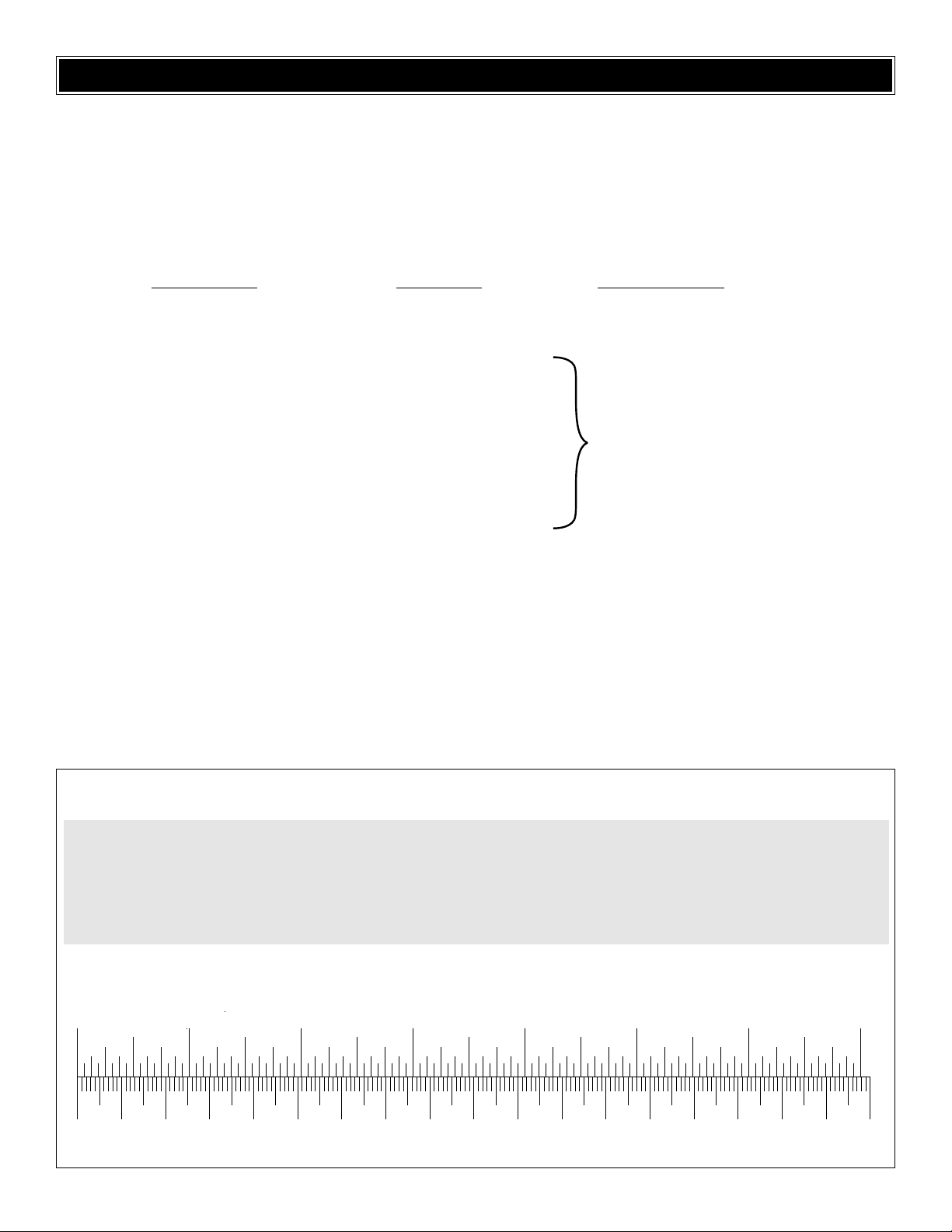
0" 1" 2" 3" 4" 5" 6" 7"
0 10 20 30 40 50 60 70 80 90 100 110 120 130 140 150 160 170 180
Inch Scale
Metric Scale
To convert inches to millimeters, multiply inches by 25.4
1/64" = .4 mm
1/32" = .8 mm
1/16" = 1.6 mm
3/32" = 2.4 mm
1/8" = 3.2 mm
5/32" = 4.0 mm
3/16" = 4.8 mm
1/4" = 6.4 mm
3/8" = 9.5 mm
1/2" = 12.7 mm
5/8" = 15.9 mm
3/4" = 19.0 mm
1" = 25.4 mm
2" = 50.8 mm
3" = 76.2 mm
6" = 152.4 mm
12" = 304.8 mm
18" = 457.2 mm
21" = 533.4 mm
24" = 609.6 mm
30" = 762.0 mm
36" = 914.4 mm
Page 7
❏ 1. If you have not done so already, remove the major
parts of the kit from the box (wings, fuselage, cowl, tail parts,
etc.) and inspect them for damage.If any parts are damaged
or missing, contact Product Support at the address or
telephone listed in the front cover.
❏ 2. Remove the masking tape and separate the ailerons
from the wing and the elevators from the stab. Use a
covering iron with a covering soc k on high heat to tighten the
model's covering if necessary. It is easy to check the wings
for dihedral at this point. Place the wings on a flat surface,
bottom side down. Each wing should lay completely flat. If
your wing does not sit flat, use a heat gun to shrink the
convex side of the wing until the wing flattens. Do not forget
to check all three wings.
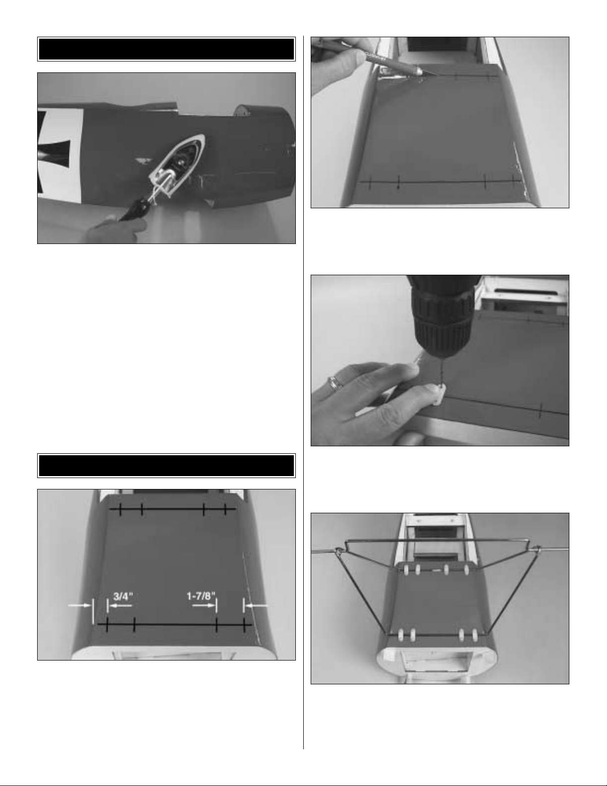
❏ 1. Securely hold the Fokker's fuselage up side down.
Find the landing gear slots at the bottom of the airplane, in
between the firewall and the bottom wing's mounting f ormer .
Make a line with a felt-tip marker along the slots as sho wn in
the picture, across the fuselage. Draw a mark on each line
3/4" [19mm] away from the fuselage's edge and then
another mark 1-7/8" [48mm] away from the edge.
❏ 2. Cut the covering along the slot's centerline as shown
above. Iron down the covering into the slot and then fuel
proof the wood exposed with epoxy.
❏ 3. Using the lines as a guide, mark and drill with a 1/16"
[1.6mm] drill bit the holes for each of the landing gear strap
screws.Harden each hole with thin CA.
❏ 4. Use sixteen #2 x 3/8" [9.5mm] screws to install all the
landing gear straps in place, to hold the main landing gear
as shown above. Your Fokker’s landing gear has been
improved from what you see in this picture .It now has crossbracing and it is pre-painted.
BUILD THE FUSELAGE
PREPARATIONS
7
Page 8
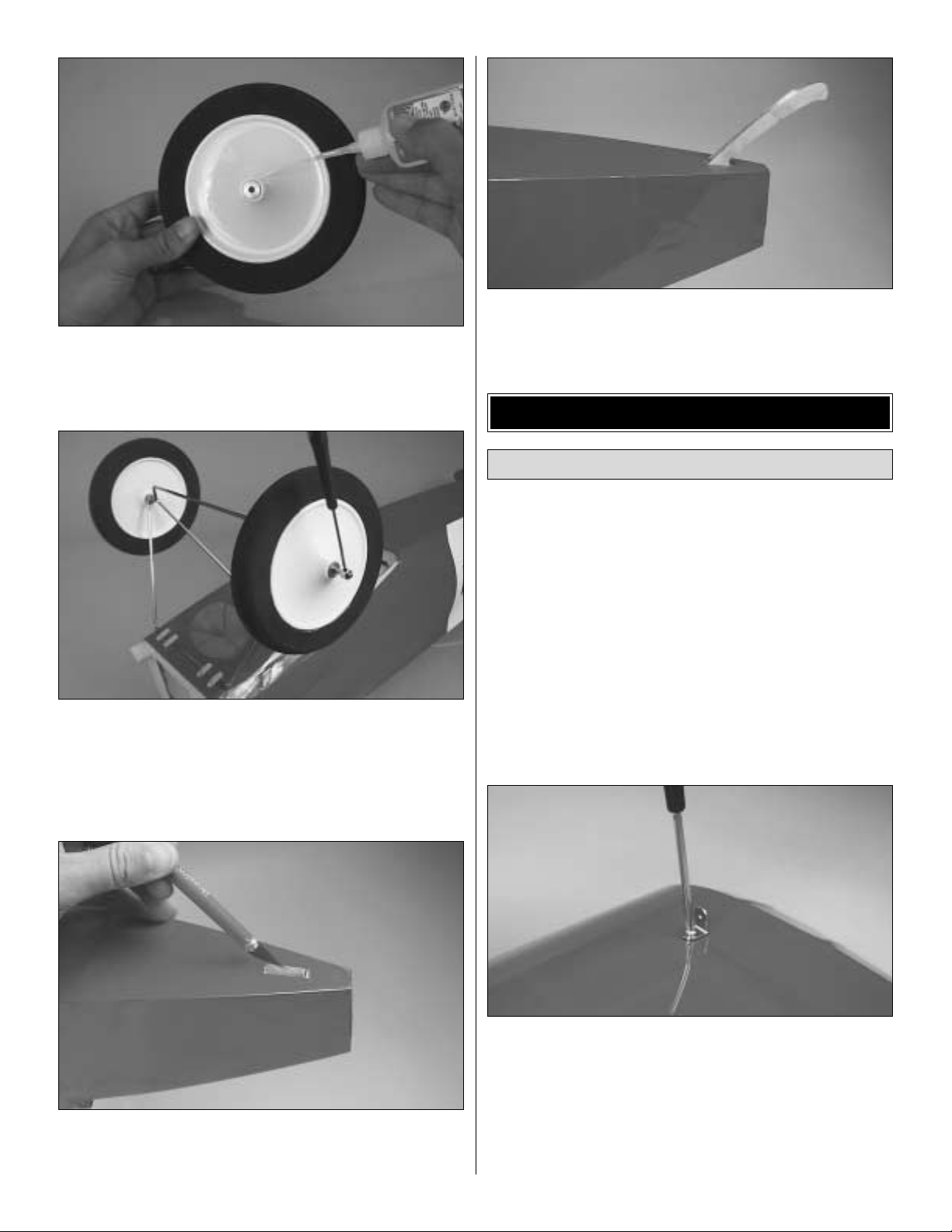
❏ 5.The scale wheels in this model have been updated and
preassembled, so it won't be necessary to glue the metal
hub to the wheel cover.
❏ 6. Temporarily mount the main wheels on the landing
gear, using two 5/32" [4mm] wheel collars with 6-32 socket
head set screws (one wheel collar is used for each wheel).
File a flat spot for the wheel collar's set screws.
❏ 7. Feel through the MonoKote to find the tailskid slot on
the aft part of the fuselage and cut it away. Use an iron to
seal the edges.
❏ 8. Sand the base of the tailskid to fit the fuselage's
tailskid slot. Once you get a good fit, mix a small amount of
epoxy and glue the tailskid in place as shown above.
Note: During the assemby and installation of the wings on the
fuselage, we will be referring to 90 degree and 60 degree
metal brackets. These brackets are permanently attached to
the wings or fuselage with screws and temporarily attached
(when the airplane is ready to fly) to the wood struts and to the
metal cabanes with socket head cap screws. One of the predrilled holes on each of the brackets has 4-40 threads. This
threaded hole is to be used for the socket head cap screws
that hold the wood struts and metal cabanes.The unthreaded
hole is to be used for the permanent sheet metal screws.
❏ 1. Find the bottom wing (the one that has two Maltese
crosses on the bottom surface), two 90 degree brac kets and
two #4 x 3/8" [9.5mm] screws.
❏ 2. There is one 1/16" [1.6mm] hole drilled out on the top
surface of the bottom wing between the tip rib and the
second rib at each end.This is where the 90 degree bracket
is installed. Harden the hole with thin CA. Check the image
shown for bracket orientation. Leave the bracket slightly
loose, as it may need to be adjusted when the wing struts
are installed.You should install a bracket on the left side and
another one on the right side of the wing.
Assemble the Bottom Wing
ASSEMBLE THE WINGS
8
Page 9
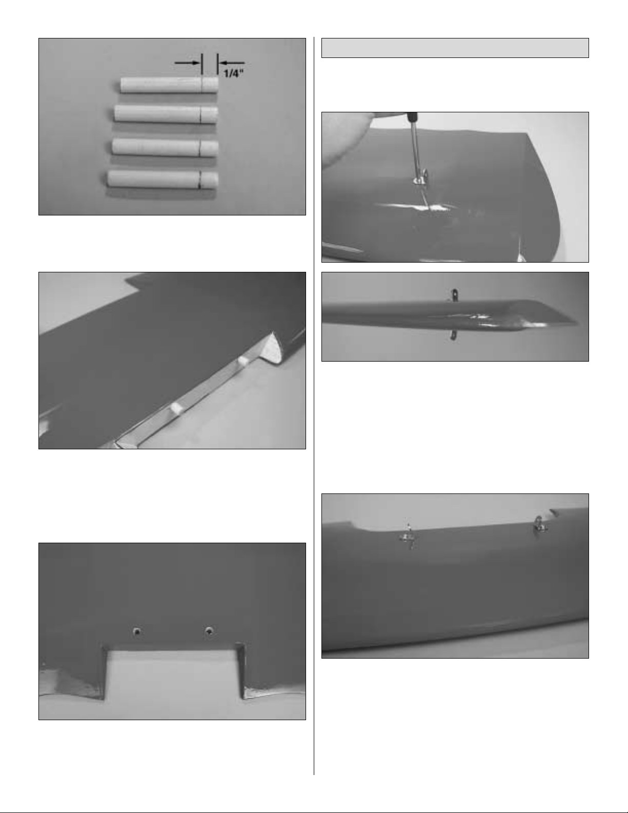
❏ 3. Find four 1/4" x 1-9/16" [6mm x 40mm] wood dowels.
Make a mark on the dowels 1/4" [6.3mm] from the end of
each as shown above.
❏ 4. Mix a small amount of epoxy and drop it into the
bottom wing's dowel holes.Also apply some epoxy on two of
the dowels.Insert the dowels up to the mark you just made,
so that just 1/4" [6.3mm] of each dowel protrudes. Clean up
any excess epoxy.
❏ 5. Feel through the MonoKote on the rear center section
of the wing for the wing bolt holes.Remember that there are
two of them. Remove the MonoKote both at the bottom and
top surfaces of the wing.
❏ 1. Find the mid wing, the only wing that does not have any
markings, four 90° brack ets and four #4 x 3/8" [9.5mm] screws.
❏ 2. There are two 1/16" holes drilled out on the top and
bottom surfaces of the mid wing between the second rib and
the third rib in from the tip. This is where the 90 degree
brackets are installed.Harden the holes with thin CA.Check
the images shown above for the bracket's orientation.Leave
the brackets slightly loose, as they may need to be adjusted
when the wing struts are installed.You should install a total
of four 90 degree brackets, one on the top and one on the
bottom of the wing ends.
❏ 3.Find two 60 degree brackets and tw o #4 x 1/2" [12mm]
screws.There are two 1/16" [1.6mm] holes drilled out on the
top sheeting of the center section. That is where the 60
degree brackets are to be installed. Harden the holes with
thin CA. Check the image shown for the bracket's
orientation. Leave the brackets slightly loose as they may
need some minor adjustments when the wing struts are
installed.Two 60 degree brackets should be installed on the
top center section of the mid wing.
Assemble the Mid Wing
9
Page 10
❏ 4.Feel through the MonoK ote and find the two pre-drilled
wing dowel holes on the leading edge of the center section
of the mid wing. Cut away the MonoKote.
❏ 5. Using the two remaining 1/4" x 1-9/16" [6mm x 40mm]
wood dowels you marked on step 3 of the previous section.
Mix a small amount of epoxy and drop it into the mid wing's
dowel holes.Also apply some epoxy on the dowels .Insert the
dowels up to the mark you just made, so that just 1/4" [6.3mm]
of each dowel protrudes.Clean up the excess epoxy.
❏ 6.Feel through the MonoKote in the center section of the
wing for the wing bolt holes.Remember that there are two of
them. Remove the MonoKote both at the bottom and top
surface of the wing.
❏ 1. The first steps in the construction of this wing will be
the installation of the ailerons and the aileron servos. The
process described here will explain how to install the right
aileron and the right aileron servo. The process has to be
repeated again to install the left aileron and the left aileron
servo, or you can work on both at the same time.
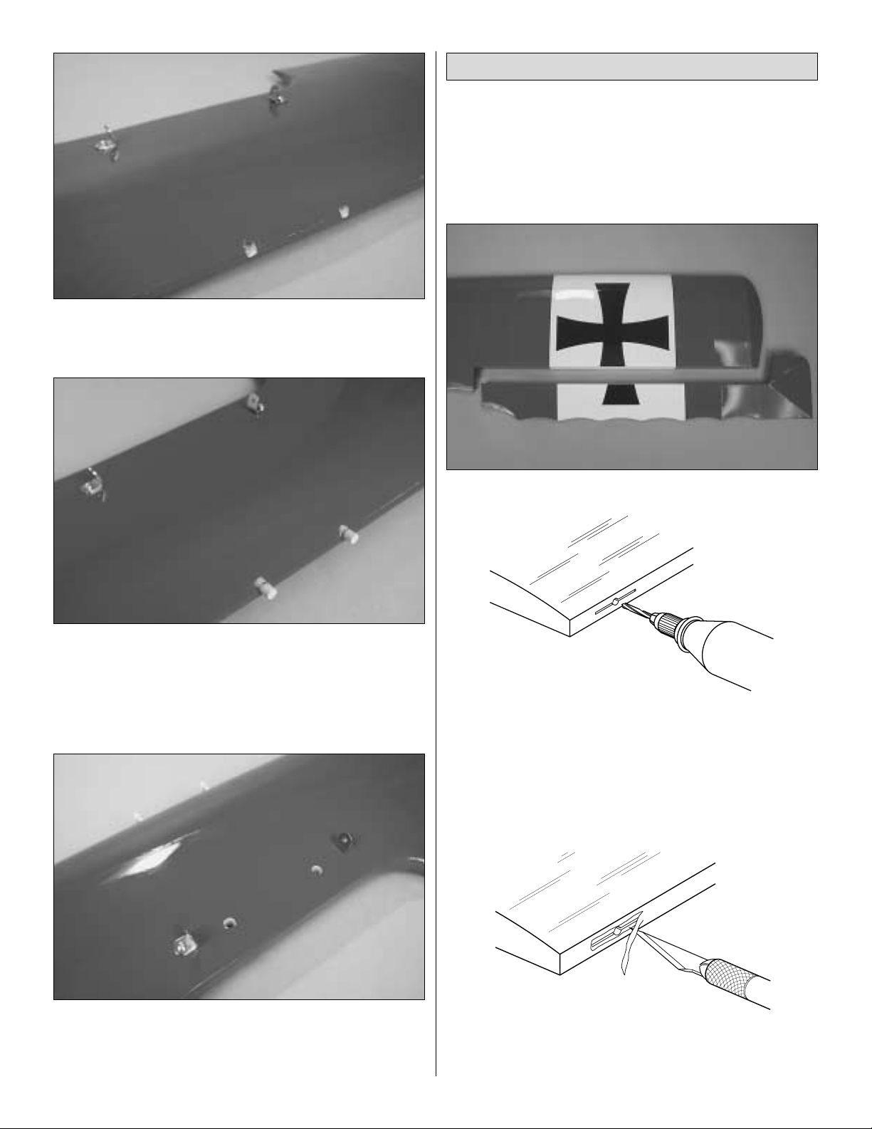
❏ 2. Locate the top wing and the right aileron.
❏ ❏ 3. Locate the pre-cut hinge slots on the top wing's
trailing edge and the leading edge of the aileron.Drill a 3/32"
[2.4 mm ] hole, 1/2" [12mm] deep in the center of each hinge
slot to allow the CA to “wick” in. Follow-up with a #11 blade
to clean-out the slots. Hint: If you have one, use a highspeed rotary tool to drill the holes.
❏ ❏ 4. Use a shar p #11 blade to cut a strip of covering
from the hinge slots in the wing and aileron.
AWAY FROM THE SLOT
CUT THE COVERING
Assemble the Top Wing
10
DRILL A 3/32" HOLE
1/2" DEEP IN THE CENTER
OF THE HINGE SLOT
Page 11
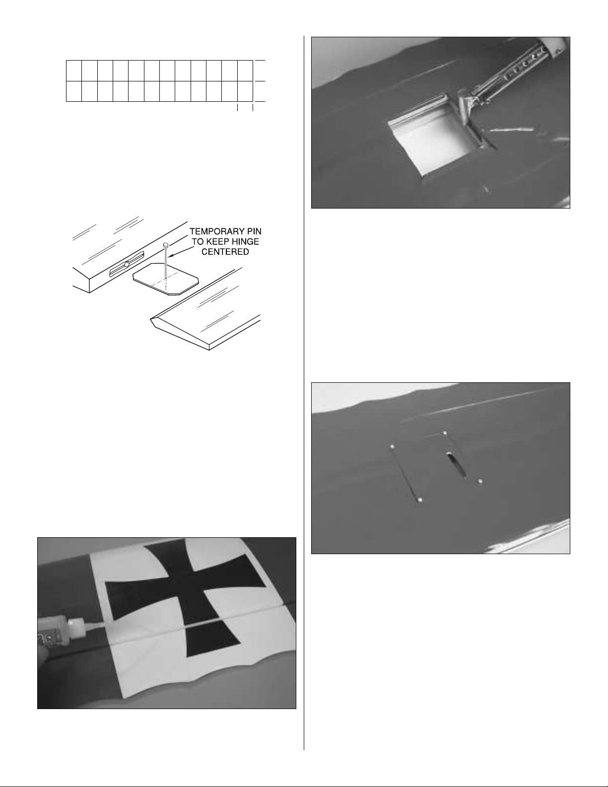
❏ ❏ 5. Cut four 3/4" x 1" [19mm x 25mm] hinges from the
CA hinge strip. Snip off the cor ners so they go in easier.
❏ ❏ 6. Test fit the ailerons to the wing with the hinges. If
the hinges do not remain centered, stick a pin through the
middle of the hinge to hold it in position.
❏ ❏ 7. Remove any pins you may have inserted into the
hinges. Adjust the aileron so that there is a small gap
between the LE of the aileron and the wing.The gap should
be small – just enough to see light through or to slip apiece
of paper through.
❏ ❏ 8. Apply six drops of thin CA to the top and bottom of
each hinge. Do not use CA accelerator. After the CA has
fully hardened, test the hinges by pulling on the aileron.
❏ ❏ 9. Locate the right aileron servo’s cover. Find the
aileron's servo opening on the bottom surface of the wing
(fourth bay in from the wing tip). Cut out the covering 1/8"
[3mm] inside the opening. Use a trim iron to seal the
covering around the edges of the opening.
❏ ❏ 10.Trial fit the aileron servo cover.It should fit snugly.
Drill four 1/16" [1.6mm] holes on the corners of the aileron
servo cover through the wing's structure. Use four #2 x 3/8"
[9.5mm] screws to hold the aileron servo cover in place.
Make sure the slot for the servo arm is nearest the wing tip.
❏ ❏ 11. Take the aileron servo cover off and wick some
thin CA into the screw holes both in the wing's structure and
in the servo covers.
1"
11
1"
3/4"
Page 12

❏ ❏ 12.Find the servo that will be used on the right aileron.
Cut down a large servo arm (the distance from theservo arm
screw to the outer servo arm hole should be at least 5/8”
[16mm]). Install the ser vo arm at 90 degrees to the servo
case.Position the servo on the servo cover so that the servo
arm is located in the middle of the slot as shown in the image
above.Outline the servo and servo mounting lugs.
❏ ❏ 13. Locate two 13/16" x 3/4" x 3/8" [20mm x 18mm x
10mm] hardwood blocks. These will be used to mount the
servos to the aileron servo cover. Mix a small amount of
epoxy. Glue the hardwood blocks along the servo mount
outlines. Make sure the grain of the hardwood blocks runs
vertical with respect to the servo cover.
❏ ❏ 14. Position the servo between the hardwood blocks.
Mark the holes for the servo screws on the hardwood blocks.
Remove the servo and drill the holes with a 1/16" [1.6mm] drill
bit.Wick some thin CA into the screw holes.Install the servo.
❏ ❏ 15. Feel through the covering the servo lead exit hole
at the center section of the bottom sheeting of the top wing.
Remove the MonoKote. Connect a 6" [152mm] servo
extension cord to one of the ends of the “Y” harness. Use
shrink tubing, tape or clips to secure the connection.Tie the
end of the 6" [152mm] servo extension to the string and pull
the extension and one leg of the “Y” harness through the
wing until it reaches the correct aileron's servo bay.
❏ ❏ 16. Connect the ser vo extension to your servo lead.
Use shrink tubing, tape or clips to secure the connection.
Gently pull on the “Y”har ness until most of the servo wire is
hidden in the wing. Mount the servo cover with the servo to
the wing.Depending on the size of your servo, y ou ma y hav e
to trim one of the wood blocks slightly.
12
At least 5/8" [16mm]
Page 13

❏ ❏ 17. Use a 90 degree ruler to find the location of the
control horn. Mark the holes for the control horn's screws.
Drill the holes with a 1/16" [1.6mm] drill bit. Harden the holes
with thin CA. Install the control horn using two 2-56 x 3/4"
[19mm] socket head cap screws and the nylon mounting
plate on the other side of the control surface.
❏ ❏ 18. Enlarge the hole on the servo arm with a Hobbico
Servo Horn Drill (or a #48 or 5/64" [2mm] drill bit). Center the
servo arm. Thread a clevis approximately 20 turns onto a
0.074" x 6" threaded one end pushrod. Slip a silicone
retainer on the clevis and connect the clevis to the aileron's
control horn. Center the aileron and make a mark on the
pushrod where it meets with the servo arm's hole. Bend the
pushrod 90 degrees up and install a Faslink on the pushrod
as shown in the sketch. Cut away any excess wire, leaving
1/16" [1.6mm] protruding from the Faslink.
❏ ❏ 19. If you have not done so, go back to step 1 and
assemble the other side of the wing the same way. Make
sure to connect the left aileron servo lead to the “Y”harness
and to pull the servo lead through the wing. Most of the “Y”
harness will stay hidden in the wing.Only the servo lead that
goes to the receiver should stick out the hole in the center of
the wing.
❏ ❏ 20. Find two 90 degree brackets and two #4 x 3/8"
[9.5mm] screws.There is one 1/16" [1.6mm] hole pre-drilled
on the bottom side of the wing, third bay in from the wing tip
on each end. This is where the 90° brackets are to be
installed with the #4 x 3/8" [9.5mm] screws. Before you
install the brackets, harden the holes with thin CA.Check the
image shown for bracket placement and orientation. Leave
the brackets slightly loose.
❏ ❏ 21. Find four 60 degree brackets and four #4 x 3/8"
[9.5mm] screws.Find four 1/16" [1.6mm] holes at the bottom
of the center section of the wing. Harden the holes with thin
CA. Install the brackets as shown above.Leave the brackets
slightly loose.
Correct Incorrect
13
FasLink
2-56 (.074") Pushrod Wire
Servo Horn
Page 14

❏ 1. Install the bottom wing onto the fuselage using two 1/4-
20 x 2" [51mm] nylon bolts.You may need to slightly sand the
wing bolt holes on the bottom and mid wing so that the wing
bolt holes line up with the wing blind nuts.If you have to do so,
apply some thin CA to the holes to harden them up.
❏ 2. Install the mid wing onto the fuselage using two
1/4-20 x 2" [51mm] nylon bolts.
❏ 3. The struts now come numbered from the factory. You
do not need to number them.This is what determines where
each strut is installed. If you install your struts correctly, they
should line up easily.You may need to slightly sand the ends
of the struts so that they sit flush against the top or bottom
surfaces of the wings. Before you do so, you should check
for wing warps and correct them. Also, be careful not to
cross-thread the bracket’s threads with the str ut bolts. The
struts should not deform the wings.
❏ 4. Strut #1 is to be installed between the mid and bottom
wing on the right side of the airplane. Use two 4-40 x 3/8"
[9.5mm] socket head cap screws and two #4 washers to
install it as shown. The SHCS should go through the wood
strut and be threaded into the metal bracket.Install Strut #4
the same way between the mid and bottom wings on the left
side of the airplane.
❏ 5. Locate the mid wing ABS cover.Trim the ABS to fit the
center section of the mid wing.Cut holes in the ABS to allow
access to the wing bolts.
❏ 6. Position the ABS cover in place. Glue the ABS cover
to the mid wing using Formula 560 or a similar glue for
plastics that dries clear.
INST ALLING THE WINGS
ON THE FUSELAGE
14
Page 15

❏ 7. Locate the last two 90 degree brackets and two
#4 x 1/2" [12mm] screws.There are two 1/16" [1.6mm] holes
drilled out on top of the fuselage by the firewall. Harden the
holes with thin CA and install the two brackets as shown in
the image above.
❏ 8. The metal cabanes provided with the kit are slightly
different from those pictured on this step, however the
installation procedure is the same. Find the metal cabanes
and four 4-40 x 1/4" [6.3mm] SHCS. Install both metal
cabanes as shown above.The SHCS should go through the
metal cabane and thread into the metal brackets.
❏ 9. Install struts #2 and #3 as shown with two 4-40 x 3/8"
[6.3mm] SHCS and two #4 flat washers. Strut #2 should be
installed on the right side of the airplane and strut #3 on the
left side of the airplane.
❏ 10. Attach the top wing to the cabane using four
4-40 x 1/4" [6.3mm] SHCS as shown above. Attach the top
wing to the wood struts using two 4-40 x 3/8" [9.5mm] SHCS
and two #4 washers.
❏ 11. Align all wood struts as shown in the picture above
and tighten all the sheet metal screws holding the brackets
that go into the wing and fuselage, sixteen screws in all.
15
Page 16

❏ 1. Cut the covering off the top of the stab saddle. Hint:
cut the covering about 1/32" [0.8mm] away from the stab
saddle edge. This will keep the covering in place after the
stab has been glued on.
❏ 2. Find the stab.The bottom of the stab has a recessed
cut out to help position the stab over the stab saddle. Find
the recessed cut-out and cut the covering 1/16" [1.6mm] on
the inside of the edge. Make sure you cut the covering, not
the wood.
❏ 3. Follow steps 3 to 7 from pages 9 - 10 to install the CA
hinges into the elevators, stab, rudder and aft fuse. The
elevators are symmetrical so there is no need to diff erentiate
them. Do not use CA on the hinges yet.
❏ 4. Separate the elevators from the stab.Position the stab
on the stab saddle. Center the trailing edge by taking
accurate measurements as shown in the sketch above.
Draw a line in the center of the stab.
❏ 5. Stand five to ten feet behind the model and view the
stab and the mid wing. They should align. If they do not
align, carefully sand the “high” side of the saddle until the
stab aligns with the wing.
❏ 6.Stick a pin into the top of the fuse near the firewall.Use
the markings on the firewall to center it. Tie a small loop in
one end of a 45" [1143mm] piece of non-elastic string such
as K & S #801 Kevlar thread (K+SR4575). Slip the loop in
the string over the T-pin.
INSTALLING THE STAB & RUDDER
16
A = A
A A
Page 17

❏ 7.Fold a piece of masking tape over the end of the string
and draw an arrow onto it. Slide the tape along the str ing
and align the arrow with one end of the stab. Swing the
string over to the same position on the other end of the stab.
While keeping the stab centered from side to side, adjust the
stab and slide the tape along the string until the arrow aligns
with both sides. Be cer tain the stab remains centered from
side to side during this process. You may have to trim the
recessed cut out at the bottom of the stab to make it fit.
❏ 8.Once the stab fits well, mix some 30 minute epoxy and
glue the stab in place. Make sure to check its alignment
again before the epoxy cures.Wipe off the excess epoxy.
❏ 9. Install the CA hinges again on the elevators and stab
and glue them in place with six drops of thin CA on each side.
❏ 10.Install two CA hinges into the rudder and aft fuse and
glue them in place with six drops of thin CA on each side.
Make sure the bottom of the rudder is aligned with the
bottom of the fuse. Also, there should be a 1/8" [3mm] gap
between the top of the stab and the bottom of the counterbalanced section of the rudder. The rudder needs to be
glued in vertically. Use a builder's square to make sure it is.
Modify the fuselage's hinge slots as necessary.
❏ 1. Remove the wings from the airplane. Cut the engine
mount template from page 35. Use spray adhesive or tape
to temporarily attach the template to the firewall. Align the
template using the vertical and horizontal lines of the
firewall.Note that the engine mount should be positioned at
different angles depending on the engine type and muffler
combination being used. The installation shown in the
manual is for a 4-stroke engine.
❏ 2. Use a small punch or a wire sharpened on one end to
transfer the engine bolt holes to the firewall by making
dimples in the wood. Remove the template.
❏ 3.Drill 7/32" [5.5mm] holes through the firewall at the marks.
Mount the engine mount to the firewall with four 8-32 x 1"
[25mm] socket head cap screws, four #8 flat washers, four #8
lock washers and four 8-32 blind nuts, but do not fully tighten
the bolts. Place the engine on the mount and adjust the width
of the mount to fit the engine.Center the molded-in “tick”marks
on the engine mount and tighten the mounting bolts.It would be
a good idea to use some Great Planes Pro Thread Locking
Compound on the engine mount bolts.
ENGINE INSTALLATION
17
Page 18

❏ 4. Position the engine so that the face of the drive washer is
4-1/2" [114mm] from the front of the fuse. Use a Great Planes
Dead Center™Engine Mount Hole Locator or your own method
to mark the engine mount holes onto the engine mount.
❏ 5.Remove the engine from the mount. Drill #29 (17/128")
holes through the mount at the marks you made. Tap 8-32
threads into the mount.Mount the engine to the mount using
four 8-32 x 3/4" [19mm] socket head cap screws, #8 flat
washers and #8 lock washers.
❏ 6.Mark the position of the throttle pushrod on the firewall.
Remove the engine. Drill a 5/32" [4mm] hole through the
firewall for the throttle pushrod. Find the 17-1/2" [444mm]
plastic outer pushrod, insert it into the hole until only about
1/4" [25mm] shows outside of the firewall as shown above,
and glue it in place.
❏ 7. Arrange the stopper
and tubes as shown in the
photo and then insert
them into the tank.Do not
tighten the screw to
expand the stopper. You
will do that in the next
step. Be certain the fuel
line weight (clunk) at the
end of the fuel line inside
the tank does not contact
the rear of the tank.
Otherwise, the line may become stuck abo v e the fuel lev el and
stop the fuel flow. Remember which is the carb line, vent and
fill tubes.You can mark the tubes with a Top Flite Panel Line
Pen if you wish.
❏ 8.Install the fuel tank in the fuse.Fit the neck through the hole
in the firewall. Be certain you install the fuel tank inside the
fuselage with the vent tube pointing up and the fill tube down.
Tighten the fuel tank screw. Use silicone sealant around the
fuel tank neck to prev ent fuel or exhaust dirt from spilling into
the fuel tank compartment.
❏ 9. Cut the fuel line in three 6" [152mm] length sections.
Install the three sections of fuel line on the three fuel tank tubes.
Mark the fuel lines so that you know what each one is for.
❏ 1. Find the .074" x 17-1/2" [444mm] threaded on end
pushrod, a clevis and a silicone retainer. Thread the clevis
RADIO INSTALLATION
18
Page 19

onto the rod approximately 20 full turns, slip the retainer on
the rod and install the rod in the throttle outer pushrod.
Install the engine and attach the clevis on the engine throttle
arm. Make sure you have a free moving linkage. Slip the
retainer on the clevis.
❏ 2. Locate three clevis, three retainers and three 0.074" x
36" [914mm] threaded one end pushrods. Thread a clevis
approximately 20 full turns onto each pushrod and slip a
retainer onto each clevis.Feel the MonoKote for pushrod e xit
holes in the aft portion of the fuselage, under the stab.There
should be a total of 3 exit holes, one for the rudder and two
for the elevators.Cut away the covering in the hole area and
insert the pushrods in their guides from the rear.
❏ 3. Connect a large nylon control horn on each clevis and
position the control horn on each control surface as shown.
Drill 3/32" [2.4mm] holes through the elevators and rudder to
accommodate the control horn's screws. Wick some thin CA
into the holes. Install the elevator control horns with four
2-56 x 1/2" [12mm] machine screws and two nylon back
plates. Install the rudder control horn with two 2-56 x 3/4"
[19mm] socket head cap screws and a nylon back plate.
Note: If you choose not to install a charge receptacle to
connect the aileron servos to the receiver, skip the following
step and go on to the next one.
❏ 4. Mark a straight line on the fuselage as shown above.
Make a mark 1-1/4" [32mm] from the firewall.Install an Ernst
Charge Receptacle as shown above using two #2 x 3/8"
[9.5mm] screws (not supplied). Inser t the male end of a 6"
[152mm] servo extension cord to the charge receptacle.The
servo plug should be left about 1/4" [6.3mm] out of the
receptacle. Use thin CA to hold it in place. This receptacle
will be used as the connector for the aileron servo. Make
sure you know the polarity of the plug. Negative (-) is the
black wire. Note how we marked the polarity on the
instruction’s model.
Correct Incorrect
19
Page 20

❏ 5. Test fit the rudder, elevator and throttle servos in the
1/8" [3mm] plywood servo tray. Depending on the size of
your servos you may have to slightly trim the mount. Place
the servos in the tray and mount them with the hardware that
came with the servos. Center the rudder servo arm. If
necessary bend the rudder pushrod slightly to align it with
the servo holes.
❏ 6. Center the rudder and make a mark on the pushrod
where it meets with the servo arm's hole you want to use.
Bend the pushrod 90 degrees up and install a Faslink on the
rudder pushrod as shown in the sketch. Cut away any
excess wire.
❏ 7. Center the elevator servo arm.Align one of the elevator
pushrods with the hole you want to use in the servo arm. Slip
two 5/32" [4mm] wheel collars onto the pushrod. Center the
elevator that pushrod controls. Bend the pushrod 90 degrees
up and install a Faslink.Center the other elevator and bend its
pushrod as shown above to mate with the first pushrod.Place
the two wheel collars as shown, drop some threadlocker onto
the threads and tighten the pushrod screws (6-32 x 1/4"
[6.3mm] SHCS). Cut the excess pushrod as shown.
❏ 8.Install a Screw-Lock Pushrod Connector on the throttle
servo arm. Insert the throttle pushrod into the connector.
Use a 4-40 x 1/8" [3mm] socket head cap screw to secure
the pushrod into the connector.Make sure that you can get
the full range of carburetor rotation with the servo rotation.
Use some Great Planes Pro Thread Locking Compound on
the SHCS to prevent it from coming loose with vibration.
❏ 9. Secure all plastic outer pushrod guides in place with
thin CA both fore and aft.
❏ 10. Install a radio switch and a charge receptacle away
from the exhaust. Glue two 1/2" x 1/4" [12mm x 6.3mm]
balsa sticks (not supplied) across the fuselage on top of the
fuel tank as shown above .These sticks will support the radio
battery and receiver.
❏ 11.Wrap the battery pack and the receiver in at least 1/4"
[6.3mm] of R/C foam rubber and install them in the fuselage.
Use shrink tubing to secure the battery to switch
connections. Glue two 1/2" x 1/4" [12mm x 6.3mm] balsa
sticks to secure the battery and receiver in place.
20
FasLink
2-56 (.074") Pushrod Wire
Servo Horn
RETAINER
Page 21

Note: If you installed the optional charge receptacle for the
aileron servo the servo extension coming from it should be
plugged into the aileron channel. If no charge receptacle
was installed for the aileron, the 6" [152mm] extension
should be connected to the aileron channel and the other
end should be left loose in the radio compartment.
❏ 12.Make a small hole through the bottom of the fuselage
and route the radio antenna to the aft fuselage.Be sure that
there is a strain relief on the antenna to keep stress off the
solder joint inside the receiver. Use a small rubber band to
keep the antenna extended.
Note: If you chose to install a charge receptacle for the
aileron servo lead, follow the next step. Otherwise skip it.
❏ 13. A 6" [152mm] servo lead extension is used on this
model to connect the aileron servos with the receiver. This
servo lead connects the “Y”harness at the bottom of the top
wing with the charge receptacle previously installed at the
base of the front left cabane strut as shown. The servo
extension can be attached with tape or it can be
permanently held in place with silicone glue.T o make it more
difficult to spot, you can use dark red LustreKote to paint the
servo lead the same color as the cabane.
Note: If you chose not to install the charge receptacle for the
aileron servo, follow the following step. Otherwise skip it.
❏ 14. Find the mid wing. Feel through the MonoKote and
find a hole by the left side of the ABS cover. Cut away the
MonoKote both in the top and bottom surface of the mid
wing.The aileron's 6" [152mm] ser vo extension in the radio
compartment should come out this hole and another 6"
[152mm] servo extension should be used to connect the top
wing's “Y” harness to this. The servo extension should be
attached to the left's cabane aft leg with tape or silicone
glue.You can paint the extension in dark red to make it more
difficult to spot.
21
Page 22

❏ 1. Mix a small amount of epoxy and glue four of the
13/16" x 3/4" x 3/8" [20mm x 18mm x 10mm] hardwood blocks
on the firewall flush with the oustide edge of the fuselage as
shown.The grain should be horizontal.
❏ 2. Cut the bottom of the fiberglass cowl open. If you use a
high speed rotary tool, this job will be much easier.Cut out the
openings in the front of the cowl. Test fit the cowl on the
fuselage. Temporarily install a prop on the engine and see if
there is enough clearance between the prop and the cowl.Trim
the cowl until you are satisfied with the fit.Remove the cowl.
❏ 3.Add an extension to the needle valve.A left-over piece
of the metal pushrod from the radio installation will work well
for this. Use paper strips to mark the location of the cowl
mounting blocks, needle valve and engine glow plug access
(if necessary). Remove the needle valve.
❏ 4.Drill 1/16" [1.6mm] holes through the cowl and through
the blocks for the cowl screws. Attach the cowl to the
fuselage using four #2 x 3/8" [9.5mm] screws and four #2
washers.Use a rotary tool to drill a hole for the extended fuel
needle and the engine glow plug access if necessary .Again,
make sure you have enough clearance between the prop
and the cowl.
❏ 5.Remove the cowl and wick some thin CA into the holes in
the hardwood blocks and let harden.Reinstall the needle valve
extension, attach the carburetor fuel line to the carburetor and
the vent line to the muffler. Use one of the Great Planes
aluminum line plugs to plug the filling line.Reinstall the cowl.
❏ 6. Now it is time to install the dummy engine. Find the
two-piece dummy engine. Cut the ABS plastic at the cut
lines.Glue the two parts together. Note: The dummy engine
will be black.
INST ALLING THE COWL
22
Page 23

❏ 7.Fit the dummy engine to your airplane.T rim the dummy
engine to allow for cooling air to pass over the engine. Glue
the dummy engine to the cowl with CA.
❏ 1. The landing gear strut covers (also called “fairings”)
are all the same length and they all fit all landing gear struts.
❏ 2.Install the forward-right covers the follo wing wa y.First test
fit the covers to make sure they fit well on the gear wire.You
may hav e to sand the covers slightly.Position one of the covers
as shown and mark the ends of the cover on the landing gear
wire with a Top Flite Panel Line Pen. The upper end of the
cover should be about 3/32" [2.4mm] away from the fuselage.
❏ 3.Roughen the surface of the landing gear wire between
the marks. Position the cover on the gear wire exactly as it
was done the previous step. Use CA to glue the ends of the
ABS cover to the landing gear wire.
❏ 4. A 5mm x 8mm x 50mm [3/16" x 5/16" x 2"] balsa stick
is included to be cut and serve for gluing blocks f or the landing
gear covers. Glue several small blocks of balsa along the
wire to tie the ABS cover to the landing gear wire to give the
covers some support. Sand the blocks so that the other half
cover fits well on the wire.
❏ 5. Use CA to glue the other half of the cover on the
landing gear.Use dark red LustreKote to touch up the co vers
and gear if needed.
INSTALLING THE LANDING GEAR
23
Page 24

❏ 6.Install all other covers the same way e xcept for the aft inner
covers.These will be installed after the landing gear wing is on.
❏ 7. Find the landing gear wing, two 5/32" [4mm] landing
gear straps and four #2 x 3/8" [9.5mm] screws .Fit the landing
gear wing onto the landing gear as shown. The fit may be
tight. There are two 1/16" [1.6mm] holes on each side of the
landing gear wing.This is where the 5/32" [4mm] landing gear
straps are to be installed using two #2 x 3/8" [9.5mm] screws
on each side. Use thin CA to harden the holes.
❏ 8. Glue the aft inner covers on with CA. Reinstall the main
wheels and wheel collars on the main gear. Permanently
tighten the wheel collar's set screws.It would be a good idea to
use Great Planes Pro Thread Locking Compound on the set
screws to prevent them from loosening up with vibration.
NOTE: If your landing gear axles protrude too much after
installing the wheels and wheel collars, you can trim them using
a rotary tool. Remember to sand off the edges so that they are
not sharp. File a flat spot for the wheel collar’s set screws.
❏ 1. Paint the inside of the cockpit black. Caution: Most
types of paint will soak through the balsa and show through
the covering. To avoid this, first clear-coat the inside of the
cockpit before painting it black.
❏ 2. After the black paint fully dries, apply the instrument
panel decal. Find the 1/4" x 16" [7mm x 40mm] cockpit
coaming and fit it around the cockpit with the ends joining at
the rear.You may have to trim it. Glue the coaming in place
with thin CA.If you wish to install a pilot, now it is the time to
do it. On the instr uction manual model we used a Williams
Brothers Standard 1/5 Pilot (WBRQ2477).
❏ 3. Use scissors or a sharp hobby knife to cut the decals
from the sheet.
❏ 4. Be certain the model is clean and free from oily
fingerprints and dust. Prepare a dishpan or small bucket with
a mixture of liquid dish soap and warm water – about one
teaspoon of soap per gallon of water.Submerse the decal in
FINAL ASSEMBLY
24
Page 25

the soap and water and peel off the paper backing. Note:
Even though the decals hav e a “sticky-back” and are not the
water transfer type , submersing them in soap & water allo ws
accurate positioning and reduces air bubbles underneath.
❏ 5. Position the decals on the model using the box photos
as a guide.Hold the decal down and with a paper towel, wipe
away all of the excess water.
❏ 6. Use a piece of soft balsa or something similar to
squeegee remaining water from under the decal. Apply the
rest of the decals the same way.
❏ 7. Find the two dummy machine guns and their sights.
Glue the sights in place with CA.
❏ 8. Position the dummy machine guns onto the ABS mid
wing cover. Sand off the base of the guns until they sit flat
and horizontal. Outline their base onto the ABS mid-wing
cover. Roughen up the paint on the mid wing cover and glue
the dummy machine guns onto the cover with CA.
❏ 9. Find the 1/16" [1.6mm] wire step. Make a mark 1/2"
[12mm] away from the bend.
❏ 10. Position the step on the bottom left side of the
fuselage 2" [52mm] away from the tr ailing edge of the bottom
wing and mark the location of the wires.
❏ 11.Use a drill with a 1/16" [1.6mm] drill bit to make holes
to accommodate the step as shown.The holes should be at
an approximately 45 degree angle from the edge.Insert the
step in the holes all the way to the mark and glue it in place
with CA. Some thick CA or epoxy should be wicked on the
inside of the fuselage to strengthen the step's grip onto the
fuselage. Clean up the fuselage with r ubbing alcohol.
25
Page 26

❏ 1.T urn on the transmitter and receiv er and center the trims.
If necessary, remove the servo arms from the servos and
reposition them so they are centered.Reinstall the screws that
hold on the servo arms.
❏ 2. With the transmitter and receiver still on, check all the
control surfaces to see if they are centered.If necessary, adjust
the clevises on the pushrods to center the control surfaces.
❏ 3. Make certain that the control surfaces and the
carburetor respond in the correct direction as shown in the
diagram.If any of the controls respond in the wrong direction,
use the servo reversing s witches in the tr ansmitter to reverse
the servos connected to those controls.Be certain the control
surfaces have remained centered. Adjust if necessary.
Use a Great Planes AccuThrow (or a ruler) to accurately
measure and set the control throw of each control surface as
indicated in the chart that follows.If your radio does not hav e
dual rates, we recommend setting the throws between the
low rate and the high rate.NOTE:The throws are measured
at the widest part of the elevators, rudder and ailerons.
IMPORTANT: The Fokker Dr .I ARF has been extensively
flown and tested to arrive at the throws at which it flies
best. Flying your model at these throws will provide you
with the greatest chance for successful first flights.If, after
you have become accustomed to the way the Fokker Dr.I
ARF flies, you would like to change the throws to suit your
taste, that is fine. However, too much control throw could
make the model difficult to control, so remember, “more is
not always better.”
These are the recommend control surface throws:
High Rate Low Rate
ELEVATOR: 1" [25mm] up 3/4" [19mm] up
1" [25mm] down 3/4" [19mm] down
RUDDER: 1-3/4" [44mm] right 1-1/4" [32mm] right
1-3/4" [44mm] left 1-1/4" [32mm] left
AILERONS: 3/4" [19mm] up 1/2" [13mm] up
3/4" [19mm] down 1/2" [13mm] down
Set the Control Throws
Check the Control Directions
GET THE MODEL READY TO FLY
26
4-CHANNEL RADIO SETUP
(STANDARD MODE 2)
4-CHANNEL
TRANSMITTER
4-CHANNEL
TRANSMITTER
4-CHANNEL
TRANSMITTER
4-CHANNEL
TRANSMITTER
ELEVATORS MOVE UP
RIGHT AILERON MOVES UP
LEFT AILERON MOVES DOWN
RUDDER MOVES RIGHT
CARBURETOR WIDE OPEN
Page 27

At this stage the model should be in ready-to-fly condition
with all of the systems in place including the engine, landing
gear, covering and paint and the radio system.
❏ 1. Use a Top Flite Panel Line Pen or 1/8" wide tape to
accurately mark the C.G. on the bottom of the mid wing on
both sides of the fuselage. The C.G. is located 2-5/8"
[67mm] back from the leading edge of the mid wing.
❏ 2.With the wings attached to the fuselage, all parts of the
model installed (ready to fly) and an empty fuel tank, lift the
model at the balance point you marked.
❏ 3.If the tail drops, the model is “tail heavy”and the battery
pack and/or receiver must be shifted forward or weight must
be added to the nose to balance.If the nose drops, the model
is “nose heavy”and the battery pack and/or receiver must be
shifted aft or weight must be added to the tail to balance. If
possible, relocate the battery pack and receiver to minimize
or eliminate any additional ballast required. If additional
weight is required, use Great Planes (GPMQ4485) “stick-on”
lead. A good place to add stick-on nose weight is to the
firewall (don't attach weight to the cowl – it is not intended to
support weight). Begin by placing incrementally increasing
amounts of weight on the top of the fuse over the fire wall until
the model balances. Once you have determined the amount
of weight required, it can be permanently attached. If
required, tail weight may be added by cutting open the
bottom of the fuse and gluing it permanently inside.Note: Do
not rely upon the adhesive on the back of the lead weight to
permanently hold it in place. Over time, fuel and exhaust
residue may soften the adhesive and cause the weight to f all
off. Use #2 sheet metal screws, RTV silicone or epoxy to
permanently hold the weight in place.
❏ 4. IMPORTANT: If you found it necessary to add any
weight, recheck the C.G.after the weight has been installed.
❏ 1.With the wings level, have an assistant help you lift the
model by the engine propeller shaft and the bottom of the
fuse under the TE of the fin.Do this several times.
❏ 2.If one wing always drops when you lift the model, it means
that side is heavy. Balance the airplane by adding weight to the
other wing tip. An airplane that has been laterally balanced
will track better in loops and other maneuvers.
No matter if you fly at an AMA sanctioned R/C club site or if you
fly somewhere on your own, you should always have your
name, address, telephone number and AMA number on or
inside your model.It is required at all AMA R/C club flying sites
and AMA sanctioned flying events. Fill out the identification tag
on page 35 and place it on or inside your model.
Follow the battery charging instructions that came with your
radio control system to charge the batteries. You should
always charge your transmitter and receiver batteries the
night before you go flying and at other times as
recommended by the radio manufacturer.
Charge the Batteries
Identify Y our Model
PREFLIGHT
Balance the Model Laterally
This is where your model should balance for your first flights.
Later, you may wish to experiment by shifting the C.G. up to
3/4" [19mm] forward or 5/8" [16mm] back to change the flying
characteristics. Moving the C.G. forward may improve the
smoothness and stability, but it may then require more speed
for takeoff and mak e it more difficult to slow for landing.Moving
the C.G. aft makes the model more maneuverable, but could
also cause it to become too difficult for you to control. In any
case, start at the location we recommend and do not at any
time balance your model outside the recommended range.
More than any other factor, the C.G. (balance point) can
have the greatest effect on how a model flies and may
determine whether or not your first flight will be
successful. If you value this model and wish to enjoy it for
many flights, DO NOT OVERLOOK THIS IMPORTANT
PROCEDURE. A model that is not proper ly balanced will
be unstable and possibly unflyable.
Balance the Model (C.G.)
27
2-5/8" [67mm]
Middle Wing
2-5/8" [67mm]
Page 28

NOTE: Checking the condition of your receiver battery pack
is highly recommended. All battery packs, whether it's a
trusty pack you've just taken out of another model, or a new
battery pack you just purchased, should be cycled, noting
the discharge capacity. Oftentimes, a weak battery pack can
be identified (and a valuable model saved!) by comparing its
actual capacity to its rated capacity. Refer to the instructions
and recommendations that come with your cycler. If you
don't own a battery cycler, perhaps you can have a friend
cycle your pack and note the capacity for you.
Carefully balance your propeller and spare propellers before
you fly. An unbalanced prop can be the single most significant
cause of vibration that can damage your model. Not only will
engine mounting screws and bolts loosen, possibly with
disastrous effect, but vibration may also damage your radio
receiver and battery. Vibration can also cause your fuel to
foam, which will, in turn, cause your engine to run hot or quit.
We use a Top Flite Precision Magnetic Prop Balancer
™
(TOPQ5700) in the workshop and keep a Great Planes
Fingertip Prop Balancer (GPMQ5000) in our flight box.
If the engine is new, follow the engine manufacturer's
instructions to break-in the engine. After break-in,
confirm that the engine idles reliably, transitions smoothly
and rapidly to full power and maintains full powerindefinitely. After you run the engine on the model, inspect
the model closely to make sure all screws remained tight,
the hinges are secure, the prop is secure and all pushrods
and connectors are secure.
Ground check the operational range of your r adio before the first
flight of the day. With the transmitter antenna collapsed and the
receiver and transmitter on, you should be able to walk at least
100 feet away from the model and still have control. Have an
assistant stand by your model and, while you w ork the controls,
tell you what the control surfaces are doing.Repeat this test with
the engine running at various speeds with an assistant holding
the model, using hand signals to show you what is happening.If
the control surfaces do not respond correctly, do not fly! Find
and correct the problem first. Look for loose servo connections
or broken wires, corroded wires on old servo connectors, poor
solder joints in your battery pack or a defective cell, or a
damaged receiver crystal from a previous crash.
Keep all engine fuel in a safe place, away from high heat,
sparks or flames, as fuel is very flammable. Do not smoke
near the engine or fuel; and remember that engine exhaust
gives off a great deal of deadly carbon monoxide .Therefore
do not run the engine in a closed room or garage.
Get help from an experienced pilot when learning to
operate engines.
Use safety glasses when starting or running engines.
Do not run the engine in an area of loose gravel or sand;the
propeller may throw such material in your face or eyes.
Keep your f ace and body as well as all spectators a wa y from the
plane of rotation of the propeller as you start and run the engine.
Keep these items away from the prop: loose clothing, shir t
sleeves, ties, scarfs, long hair or loose objects such as
pencils or screwdrivers that may fall out of shirt or jacket
pockets into the prop.
Use a “chicken stick” or electric starter to star t the engine.
Do not use your fingers to flip the propeller .Make certain the
glow plug clip or connector is secure so that it will not pop
off or otherwise get into the running propeller.
Make all engine adjustments from behind the rotating propeller .
The engine gets hot! Do not touch it during or right after
operation. Make sure fuel lines are in good condition so fuel
will not leak onto a hot engine, causing a fire.
To stop a glow engine, cut off the fuel supply by closing off the
fuel line or following the engine manufacturer's
recommendations. Do not use hands, fingers or any other
body part to try to stop the engine.To stop a gasoline powered
engine an on/off switch should be connected to the engine coil.
Do not throw anything into the propeller of a running engine.
Failure to follow these safety precautions may result
in severe injury to yourself and others.
ENGINE SAFETY PRECAUTIONS
Range Check
Ground Check
Balance Propellers
28
Page 29

Read and abide by the following Academy of Model
Aeronautics Official Safety Code:
1. I will not fly my model aircraft in sanctioned events, air
shows, or model flying demonstrations until it has been
proven to be airworthy by having been previously
successfully flight tested.
2. I will not fly my model aircraft higher than approximately
400 feet within 3 miles of an airport without notifying the
airpor t operator. I will give right of way to and avoid flying in
the proximity of full scale aircraft. Where necessary an
observer shall be used to supervise flying to avoid having
models fly in the proximity of full scale aircraft.
3. Where established, I will abide by the safety rules for the
flying site I use and I will not willfully and deliberately fly my
models in a careless, reckless and/or dangerous manner.
7. I will not fly my model unless it is identified with my
name and address or AMA number, on or in the model.
9. I will not operate models with pyrotechnics (any device
that explodes, burns, or propels a projectile of any kind).
1. I will have completed a successful radio equipment
ground check before the first flight of a ne w or repaired model.
2. I will not fly my model aircraft in the presence of
spectators until I become a qualified flier, unless assisted b y
an experienced helper.
3. I will perform my initial turn after takeoff away from the
pit or spectator areas and I will not thereafter fly over pit or
spectator areas, unless beyond my control.
4. I will operate my model using only radio control frequencies
currently allowed by the Federal Communications Commission.
Since the Fokker Dr.I ARF qualifies as a “giant scale”model
and is therefore eligible to fly in IMAA events,we've printed
excerpts from the IMAA Safety Code, which follows.
Definition: For the purpose of the following IMAA Safety
Code, the term Giant Scale shall refer to radio controlled
model aircraft, either scale or non-scale, which have a
wingspan of 80 inches or more for monoplanes and 60
inches or more for multi-winged model aircraft and have a
ramp weight (fueled and ready to fly) of 55 lbs.or less.
1.1 Adherence to Code: This safety code is to be
strictly followed.
1.2 The most current AMA Safety Code in effect is to be
observed. However, the competition sections of the code
may be disregarded.
3.4 Flight Testing: All Giant Scale R/C aircraft are to have been
flight tested and flight trimmed with a minimum of six flights
before the model is allowed to fly at an IMAA Sanctioned event.
3.5 Proof of Flight: The completing and signing of the
Declaration section of the Safety Inspection f orm by the pilot
(or owner) shall document as fact that each aircraft has
been successfully flight-tested and proven airworthy prior to
an IMAA event.
5.1 All magneto spark ignition engines must have a coil
grounding switch on the aircraft to stop the engine. This will
also prevent accidental starting of the engine.This switch shall
be readily available to both pilot and helper.This switch is to be
operated manually and without the use of the radio system.
5.2 Engines with battery power ignition systems must have
a switch to turn off the power from the battery pack to
disable the engine from firing. This will also prevent
accidental starting of the engine.This switch shall be readily
available to both pilot and helper. This switch shall be
operated manually and without the use of the Radio System.
5.3 There must also be a means to stop the engine from the
transmitter. The most common method is to close the
carburetor throat completely using throttle trim, however,
other methods are acceptable. This requirement applies to
all glow/gas ignition engines regardless of size.
Section 5.0: Emergency Engine Shut Off
Section 3.0: Safety Check
Section 1.0: Safety Standard
IMAA SAFETY CODE (
EXCERPT
)
Radio Control
General
AMA SAFETY CODE (
EXCERPT
)
29
Page 30

6.1 All transmitters must be FCC type certified.
6.2 FCC Technician or higher-class license required for 6
meter band operation only.
The following recommendations are included in the Safety
Code not to police such items, but rather to offer basic
suggestions for enhanced safety.
Servos need to be of a rating capable to handle the loads that
the control surfaces impose upon the servos.Standard servos
are not recommended for control surfaces. Servos should be
rated heavy-duty. For flight-critical control functions a
minimum of 45 inch/ounces of torque should be considered.
This should be considered a minimum for smaller aircraft and
higher torque servos are strongly encouraged for larger
aircraft. The use of one ser vo for each aileron and one for
each elevator half is strongly recommended. Use of dual
servos is also recommended for larger aircraft.
On-board batteries shall be 1000 mAh up to 20 lbs., 1200 mAh
to 30 lbs., 1800 mAh to 40 lbs. and 2000 mAh over 40 lbs.
flying weight. The number and size of servos, size and loads
on control surfaces and added features should be considered
as an increase to these minimums.Batteries should be able to
sustain power to the onboard radio components for a minim um
of one hour total flying time before recharging.
Redundant and fail-safe battery systems are recommended.
The use of anti-glitch devices for long leads are recommended.
There is no maximum engine displacement limit, as it is the
position of this body that an underpowered aircraft presents
a greater danger than an overpowered aircraft.However , the
selection of engine size relative to airframe strength and
power loading mandates good discretionary judgment by
the designer and builder .Current AMA maximums for engine
displacement are 6.0 cu. in. for two-stroke and 9.6 cu. in. for
four-stroke engines. These maximums apply only to AMA
Sanctions concerning competition events (such as 511, 512,
515 and 520) and, as such, the maximums apply. All IMAA
(non competition) events should be sanctioned as Class “C”
events, in which these engine size maximums do not apply.
Generally, it is recommended that no attempt should be made
to fly a radio controlled model aircraft with a gasoline engine in
which the model aircraft weight would exceed twelve (12)
pounds (underpowered) per cubic inch of engine displacement,
or be less than five (5) pounds (overpowered) per cubic inch of
engine displacement. Example: Using a 3 cu. in. engine, a
model would likely be underpowered at an aircraft weight
greater than 36 pounds. With the same engine, an aircraft
weighing less than 15 pounds would likely be overpowered.
Servo arms and wheels should be rated heavy duty. Glassfilled servo arms and control horns are highly recommended.
Control surfaces linkages are listed in order of preference:
1. Cable system (pull-pull). A tiller bar is highly recommended
along with necessary bracing.
2. Arrow Shaft, fiberglass or aluminum, 1/4" or 5/16" O.D.
bracing every six (6) to ten (10) inches is highly recommended.
3. Tube-in-tube (nyrod). Bracing every few inches is highly
recommended. Inner tube should be totally enclosed in
outer tube.
4. Hardwood dowel, 3/8" O.D. bracing every six (6) to ten
(10) inches is highly recommended.
Hinges should be rated heavy duty and manufactured for
Giant Scale use primarily. Homemade and original design
hinges are acceptable if determined to be adequate for the
intended use.
Clevis (steel, excluding heavy-duty ball links) and
attachment hardware should be heavy duty 4-40 threaded
rod type. 2-56 threaded size rod is acceptable for some
applications (e.g. throttle). Clevis is to have lock nuts and
sleeve or spring keepers.
Propeller tips should be painted or colored in a visible and
contrasting manner so as to increase the visibility of the
propeller tip arc.
❏ 1.Fuel proof all areas exposed to fuel or exhaust residue
such as the cowl ring, cowl mounting blocks, wing saddle
area, etc.
❏ 2. Check the C.G. according to the measurements
provided in the manual.
❏ 3. Be certain the battery and receiver are securely
mounted in the fuse. Simply stuffing them into place with
foam rubber is not sufficient.
During the last few moments of preparation your mind
may be elsewhere anticipating the excitement of the first
flight. Because of this, you may be more likely to overlook
certain checks and procedures that should be performed
before the model is flown.To help avoid this, a checklist is
provided to make sure these important areas are not
overlooked. Many are covered in the instruction manual,
so where appropriate, refer to the manual for complete
instructions. Be sure to check the items off as they are
completed (that's why it's called a
check list!
).
CHECK LIST
Additional IMAA Recommendations
Section 6.0: Radio Requirements
30
Page 31

❏ 4. Extend your receiver antenna and make sure it has a
strain relief inside the fuselage to keep tension off the solder
joint inside the receiver.
❏ 5. Balance your model
laterally
as explained in
the instructions.
❏ 6. Use thread locking compound to secure critical
fasteners such as the set screws that hold the wheel axles
to the struts, screws that hold the carburetor arm (if
applicable), screw-lock pushrod connectors, etc.
❏ 7. Add a drop of oil to the axles so the wheels will turn freely.
❏ 8. Make sure all hinges are securely glued in place.
❏ 9. Reinforce holes for wood screws with thin CA where
appropriate (servo mounting screws, cowl mounting
screws, etc.).
❏ 10. Confirm that all controls operate in the correct
direction and the throws are set up according to the manual.
❏ 11. Make sure there are silicone retainers on all the
clevises and that all servo arms are secured to the servos
with the screws included with your radio.
❏ 12. Secure connections between servo wires and
Y-connectors or servo extensions and the connection between
your battery pack and the on/off switch with vinyl tape, heat
shrink tubing or special clips suitable for that purpose.
❏ 13. Make sure any servo extension cords you may have
used do not interfere with other systems (servo arms,
pushrods, etc.).
❏ 14.Secure the pressure tap (if used) to the muffler with high
temp RTV silicone, thread locking compound or J.B. Weld.
❏ 15. Make sure the fuel lines are connected and are
not kinked.
❏ 16. Use an incidence meter to check the wing for twists
and attempt to correct before flying.
❏ 17. Balance your propeller (and spare propellers).
❏ 18. Tighten the propeller nut and spinner.
❏ 19. Place your name, address, AMA number and
telephone number on or inside your model.
❏ 20. Cycle your receiver battery pack (if necessary) and
make sure it is fully charged.
❏ 21. If you wish to photograph your model, do so before
your first flight.
❏ 22. Range check your radio when y ou get to the flying field.
The Fokker Dr .I ARF is a great-flying model that flies smoothly
and predictably. The Fokker Dr. I ARF does not, however,
possess the self-recovery characteristics of a primary R/C
trainer and should be flown only by experienced R/C pilots.
The Great Planes Fokker Dr. I is easier to fly than it looks.
This airplane handles really well on grass and as long as
throttle is not applied suddenly it takes off easily. In fact,
easier than many tail draggers. In flight, this model is very
neutral, meaning that the model will stay in the flying attitude
that you put it into. Elevator, aileron and rudder control is
very positive at all speeds and the model's stall is so soft it
is almost non-existent to the point that the pilot retains full
aileron and rudder control during prolonged full elevator
stalls. Its slow speed characteristics are excellent and that
coupled to the excellent maneuverability of the airplane
makes it possible for this airplane to turn on a dime without
losing altitude. On landing the Fokker Dr. I requires slightly
more attention than any other tail dragger because of the
narrow landing gear. Again, landing on grass if possible is
the best solution. After several flights you will feel so
comfortable with this airplane that you will forget all those
things that make you nervous now. Its flying performance
will impress you and also everybody else at the field.
A fully cowled engine may run at a higher temperature than
an un-cowled engine. For this reason, the fuel mixture
should be richened so the engine runs at about 200 rpm
below peak speed. By running the engine slightly r ich, you
will help prevent dead-stic k landings caused by overheating.
CAUTION (THIS APPLIES TO ALL R/C AIRPLANES):
If, while flying, you notice any unusual sounds, such as a
low-pitched “buzz,” this may be an indication of control
surface “flutter.” Because flutter can quickly destroy
components of your airplane, any time you detect flutter
you must immediately cut the throttle and land the
airplane! Check all servo grommets for deterioration (this
will indicate which surface fluttered) and make sure all
pushrod linkages are slop-free. If it fluttered once, it will
probably flutter again under similar circumstances unless
you can eliminate the slop or flexing in the linkages.Here
are some things which can result in flutter: Excessive
hinge gap;Not mounting control horns solidly; Sloppy fit of
clevis pin in horn; Elasticity present in flexible plastic
pushrods; Side-play of pushrod in guide tube caused by
tight bends; Sloppy fit of Z-bend in servo arm; Insufficient
glue used when gluing in the elevator joiner wire or aileron
torque rod; Excessive “play” or “backlash” in ser vo gears;
and Insecure servo mounting.
Fuel Mixture Adjustments
FLYING
31
Page 32

Before you get ready to takeoff, see how the model handles
on the ground by doing a few practice runs at low speeds
on the runway. Hold “up” elevator to keep the tail skid on the
ground. If you need to calm your nerves before the maiden
flight, shut the engine down and bring the model back into
the pits.Top off the fuel, then check all fasteners and control
linkages for peace of mind.
The Fokker Dr. I ARF has a narrow, scale landing gear that
requires more attention on take off and on landing runs than
wider gears. The Fokker Dr. I ARF does not handle cross
winds too well while on the ground, so try to always land and
take off into the wind. When you're ready, point the model
straight down the wind, hold a bit of up elevator to keep the
tail on the ground, then gradually advance the throttle. As
the model gains speed decrease up elevator allo wing the tail
to come off the ground. One of the most important things to
remember with a tail dragger is to always be ready to apply
right rudder to counteract engine torque. Gain as much
speed as your runway and flying site will practically allow
before gently applying up elevator, lifting the model into the
air.At this moment it is likely that you will need to apply more
right rudder to counteract engine torque. Be smooth on the
elevator stic k, allo wing the model to estab lish a gentle climb
to a safe altitude before turning into the traffic pattern. Be
prepared because the Fokker will come off the ground very
quickly once full power is applied.
For reassurance and to keep an eye on other traffic, it is a
good idea to have an assistant on the flight line with you.Tell
him to remind you to throttle back once the plane gets to a
comfortable altitude.While full throttle is usually desirable for
takeoff, most models fly more smoothly at reduced speeds.
Take it easy with the Fokker Dr.I ARF for the first few flights,
gradually getting acquainted with it as you gain confidence.
Adjust the trims to maintain straight and level flight. After
flying around for a while and while still at a safe altitude with
plenty of fuel, practice slow flight and execute practice
landing approaches by reducing the throttle to see how the
model handles at slower speeds.Add power to see how she
climbs as well. Continue to fly around, executing various
maneuvers and making mental notes (or having your
assistant write them down) of what trim or C.G. changes
may be required to fine tune the model so it flies the wa y you
like. Mind your fuel level, but use this first flight to become
familiar with your model before landing.
To initiate a landing approach, lower the throttle while on the
downwind leg. Allow the nose of the model to pitch
downward to gradually bleed off altitude. This airplane is
very draggy and it loses speed quickly, so keep a little
throttle until the airplane is on the runway. Continue to lose
altitude, but maintain airspeed by k eeping the nose down as
you turn onto the crosswind leg.Make your final turn toward
the runway (into the wind) keeping the nose down to
maintain airspeed and control. Level the attitude when the
model reaches the runway threshold, modulating the throttle
as necessary to maintain your glide path and airspeed. If
you are going to overshoot, smoothly advance the throttle
(always ready on the right rudder to counteract torque) and
climb out to make another attempt. When you're ready to
make your landing flare and the model is a foot or so off the
deck, smoothly increase up elevator until it gently touches
down. Once the model is on the runway and has lost flying
speed, hold up elevator to place the tail on the ground.
One final note about flying your model. Have a goal or flight
plan in mind for every flight. This can be learning a new
maneuver(s), improving a maneuver(s) y ou already kno w, or
learning how the model behaves in certain conditions (such
as on high or low rates). This is not necessarily to improve
your skills (
though it is never a bad idea!
), but more
importantly so you do not surprise yourself by impulsively
attempting a maneuver and suddenly finding that you'v e run
out of time, altitude or airspeed. Every maneuver should be
deliberate, not impulsive.For example, if you're going to do
a loop, check your altitude, mind the wind direction
(anticipating rudder corrections that will be required to
maintain heading), remember to throttle back at the top and
make certain you are on the desired rates (high/low rates).
A flight plan greatly reduces the chances of crashing your
model just because of poor planning and impulsive moves.
Remember to think.
Have a ball! But always stay in control
and fly in a safe manner.
GOOD LUCK AND GREAT FLYING!
Landing
Flight
Takeoff
32
Page 33

33
BUILDING NOTES
Kit Purchased Date: _______________________
Where Purchased: _________________________
Date Construction Started: __________________
Date Construction Finished: _________________
Finished Weight: __________________________
Date of First Flight: ________________________
FLIGHT LOG
Page 34

Great Planes®Accu-Throw
™
Control Surface Deflection Meter
GPMR2405
One leading cause of crashes is flying an airplane with its
control throws set differently from those recommended in
the instructions. The Great Planes AccuThrow™lets you
quickly and easily measure actual throws first, so you can
make necessary corrections before you fly. Large, no-slip
rubber feet provide a firm grip on covered surfaces without
denting or marring the finish. Spring tension holds
AccuThrow’s plastic ruler steady by each control surface.
Curved to match control motions, the ruler provides exact
readings in both standard or metric measurements.
Top Flite®Power Point®Wood Propellers
(TOPQ5000-5200)
• Swept tip design reduces noise.
• Lighter, quieter, and more efficient than ever!
• More thrust for greater power.
The strict quality control used when manufacturing Power
Point props ensures symmetric pitch: at any given point on
one blade, the pitch will exactly match the pitch at the same
point on the opposite blade. This accuracy reduces prop
vibration and boosts thrust at any rpm.Combined with a new
airfoil design and the "P ow er P oint" tip , these props are a top
choice for modelers of every skill level. Lighter than maple
props of the same size, these fuelproofed beechw ood props
reduce rotational mass, letting your engine produce more
power with less work.Wood construction also makes Power
Point props stiffer than nylon, so they perform predictably
throughout the full rpm range.
Great Planes®Dead Center™Engine Mount Hole
Locator (GPMR8130)
Improperly drilled mount holes can over-stress the mount,
cause bolts to bind, or permit destructive vibration — but
that doesn’t happen with Great Planes' pen-sized tool. Just
position the engine on the mount, and insert the selfcentering cone in the mounting hole.Twist the shaft, and the
drill bit inside will mark the spot with a small star ter hole. It’s
that fast and easy to use — and stores away in its own
protective plastic tube when you’re done. A workshop must!
O.S. .70 Surpass Engine
(OSMG0870)
Give a sharper kick to your Fokk er Dr .I aerobatic maneuvers
with the 1.1 horsepower (at 11,000 rpm) of O.S.Engines’ .70
Surpass. Weighing just 20.1 ounces, this high-performance
4-stroke has a helix gear-driven camshaft on the front end
and a dependable updraft carburetor in back. It’s generous
with power, but economical on fuel consumption—and
comes with both muffler and glow plug to increase your
value.Also included: warranty protection for 5 years!
34
OTHER ITEMS AVAILABLE FROM GREAT PLANES
Page 35

35
 Loading...