

Page 1
WARRANTY
Great Planes®Model Manufacturing Co.guarantees this kit to be free from defects in both material and workmanship
at the date of purchase.This warranty does not cover any component parts damaged by use or modification.In no case
shall Great Planes’ liability exceed the original cost of the purchased kit. Fur ther, Great Planes reserves the right
to change or modify this warranty without notice.
In that Great Planes has no control over the final assembly or material used for final assembly, no liability shall be
assumed nor accepted for any damage resulting from the use by the user of the final user-assembled product.By the act
of using the user-assembled product, the user accepts all resulting liability.
If the buyers are not prepared to accept the liability associated with the use of this product,they are advised
to return this kit immediately in new and unused condition to the place of purchase.
READ THROUGH THIS INSTRUCTION MANUAL
FIRST. IT CONTAINS IMPORTANT INSTRUCTIONS
AND WARNINGS CONCERNING THE ASSEMBLY
AND USE OF THIS MODEL.
GPMZ0245 for GPMA1365 V1.0Entire Contents © Copyright 2003
Champaign, Illinois
Telephone: (217) 398-8970 ext. 5
Fax:(217) 398-7721
INSTRUCTION MANUAL
Wingspan: 74 in [1880mm]
Length: 69 in [1755mm]
Wing Area: 1048 sq in [67.6 dm2]
Weight: 12-13.5 lb [5440–6120 g]
Wing Loading: 26-30 oz/sq ft [79-92 g/dm2]
Radio: 4 channel, 4 servos with a minimum torque rating of 54 oz. in.
1 servo with a minimum torque rating of 87 oz. in.
1 servo with a minimum torque rating of 30 oz. in.
Engine: 1.20 -1.60 cu in [19.5–26cc] two-stroke
1.20-1.80 cu in [19.5–29.5cc] four-stroke
Page 2

SAFETY PRECAUTIONS . . . . . . . . . . . . . . . . . . . . . . . 2
DECISIONS YOU MUST MAKE. . . . . . . . . . . . . . . . . . . 3
Radio Equipment . . . . . . . . . . . . . . . . . . . . . . . . . . . . 3
Engine Recommendations . . . . . . . . . . . . . . . . . . . . . 3
ADDITIONAL ITEMS REQUIRED . . . . . . . . . . . . . . . . . 3
Hardware and Accessories. . . . . . . . . . . . . . . . . . . . . 3
Optional Supplies and Tools . . . . . . . . . . . . . . . . . . . . 3
KIT INSPECTION . . . . . . . . . . . . . . . . . . . . . . . . . . . . . 4
Ordering Replacement Parts. . . . . . . . . . . . . . . . . . . . 5
Important Building Notes . . . . . . . . . . . . . . . . . . . . . . 5
Metric Conversions . . . . . . . . . . . . . . . . . . . . . . . . . . . 5
PREPARATIONS. . . . . . . . . . . . . . . . . . . . . . . . . . . . . . 6
ASSEMBLE THE WING. . . . . . . . . . . . . . . . . . . . . . . . . 6
Install the Ailerons . . . . . . . . . . . . . . . . . . . . . . . . . . . 6
Install the Aileron Servos & Pushrods. . . . . . . . . . . . . 7
Join the Wing . . . . . . . . . . . . . . . . . . . . . . . . . . . . . . . 9
ASSEMBLE THE FUSELA GE . . . . . . . . . . . . . . . . . . . 10
Install the Tail Gear & Landing Gear . . . . . . . . . . . . . 10
Install the Stab, Elevator and Rudder . . . . . . . . . . . . 12
Install the Elevator & Rudder Pushrods & Servos . . . 13
Install the Engine, Fuel Tank and Throttle Servo . . . . 14
INST ALL THE CO WL. . . . . . . . . . . . . . . . . . . . . . . . . . 15
RADIO INSTALLATION . . . . . . . . . . . . . . . . . . . . . . . . 17
FINISHING TOUCHES. . . . . . . . . . . . . . . . . . . . . . . . . 18
Apply the Decals . . . . . . . . . . . . . . . . . . . . . . . . . . . 18
PREP ARE T O FLY . . . . . . . . . . . . . . . . . . . . . . . . . . . 18
Check the Control Directions . . . . . . . . . . . . . . . . . . 18
Set the Control Throws. . . . . . . . . . . . . . . . . . . . . . . 19
Balance the Model (C.G.) . . . . . . . . . . . . . . . . . . . . . 19
Balance the Model Laterally . . . . . . . . . . . . . . . . . . . 20
3-D PERFORMANCE SETTINGS . . . . . . . . . . . . . . . . 20
3-D Control Throws. . . . . . . . . . . . . . . . . . . . . . . . . . 20
3-D Servo Arms . . . . . . . . . . . . . . . . . . . . . . . . . . . . 20
3-D Servos. . . . . . . . . . . . . . . . . . . . . . . . . . . . . . . . 20
PREFLIGHT . . . . . . . . . . . . . . . . . . . . . . . . . . . . . . . . 21
Identify Your Model . . . . . . . . . . . . . . . . . . . . . . . . . . 21
Charge the Batteries. . . . . . . . . . . . . . . . . . . . . . . . . 21
Balance Propellers . . . . . . . . . . . . . . . . . . . . . . . . . . 21
Ground Check . . . . . . . . . . . . . . . . . . . . . . . . . . . . . 22
Range Check . . . . . . . . . . . . . . . . . . . . . . . . . . . . . . 22
ENGINE SAFETY PRECAUTIONS . . . . . . . . . . . . . . . 22
AMA SAFETY CODE . . . . . . . . . . . . . . . . . . . . . . . . . 22
CHECK LIST. . . . . . . . . . . . . . . . . . . . . . . . . . . . . . . . 23
FLYING . . . . . . . . . . . . . . . . . . . . . . . . . . . . . . . . . . . . 23
Takeoff . . . . . . . . . . . . . . . . . . . . . . . . . . . . . . . . . . . 23
Flight . . . . . . . . . . . . . . . . . . . . . . . . . . . . . . . . . . . . 24
Aerobatics . . . . . . . . . . . . . . . . . . . . . . . . . . . . . . . . 24
Landing . . . . . . . . . . . . . . . . . . . . . . . . . . . . . . . . . . 24
For the latest technical updates or manual corrections to the
Extra 300S visit the Great Planes web site at
www
.greatplanes.com
. Open the “Airplanes” link, then
select the Extra 300S 1.60 ARF . If there is new technical
information or changes to this model a “tech notice” box will
appear in the upper left corner of the page.
1. Your Extra 300S should not be considered a toy, but rather a
sophisticated, working model that functions very much like a fullsize airplane.Because of its performance capabilities, the Extra
300S, if not assembled and operated correctly, could possibly
cause injury to yourself or spectators and damage to property.
2. You must assemble the model according to the
instructions.Do not alter or modify the model, as doing so may
result in an unsafe or unflyable model. In a few cases the
instructions may differ slightly from the photos.In those instances
the written instructions should be considered as correct.
3. You must take time to build straight, true and strong.
4. You must use an R/C radio system that is in first-class
condition, and a correctly sized engine and components
(fuel tank, wheels, etc.) throughout the building process.
5. You must correctly install all R/C and other components so
that the model operates correctly on the ground and in the air .
6. You must check the operation of the model before every
flight to insure that all equipment is operating and that the
model has remained structurally sound. Be sure to check
clevises or other connectors often and replace them if they
show any signs of wear or fatigue.
7. If you are not already an experienced R/C pilot, you
should fly the model only with the help of a competent,
experienced R/C pilot.
8. While this kit has been flight tested to exceed normal
use, if the plane will be used for extremely high stress
flying, the modeler is responsible for taking steps to
reinforce the high stress points.
9. WARNING: The cowl and wheel pants included in this kit
are made of fiberglass, the fibers of which may cause ey e, skin
and respiratory tract irritation. Never blow into a part (wheel
pant, cowl) to remove fiberglass dust, as the dust will blow
back into your eyes. Always wear safety goggles, a particle
mask and rubber gloves when grinding, drilling and sanding
fiberglass parts. Vacuum the parts and the work area
thoroughly after working with fiberglass parts.
Remember:Take your time and follow the instructions to
end up with a well-built model that is straight and true.
NOTE:W e, as the kit manuf acturer , pro vide you with a top quality
kit and great instructions, but ultimately the quality of your
finished model depends on how you build it;therefore, w e cannot
in any way guarantee the performance of your completed model,
and no representations are expressed or implied as to the
performance or safety of your completed model.
PRO TECT YOUR MODEL,Y OURSELF
& OTHERS...FOLLOW THESE
IMPORTANT SAFETY PRECAUTIONS
TABLE OF CONTENTS
2
Page 3

If you have not flown this type of model before, we
recommend that you get the assistance of an experienced
pilot in your R/C club for your first flights. If you’re not a
member of a club, your local hobby shop has information
about clubs in your area whose membership includes
experienced pilots.
In addition to joining an R/C club, we strongly recommend y ou
join the AMA (Academy of Model Aeronautics). AMA
membership is required to fly at AMA sanctioned clubs.There
are over 2,500 AMA chartered clubs across the country.
Among other benefits, the AMA provides insurance to its
members who fly at sanctioned sites and events. Additionally,
training programs and instructors are available at AMA club
sites to help you get started the right way. Contact the AMA at
the address or toll-free phone number below:
Academy of Model Aeronautics
5151 East Memorial Drive
Muncie, IN 47302-9252
Tele. (800) 435-9262
Fax (765) 741-0057
Or via the Internet at: http://www.modelaircraft.org
This is a partial list of items required to finish the Extra 300S
that may require planning or decision making before starting to
build.Order numbers are provided in parentheses.
Four channel radio and f our channel receiv er (a six channel
computer radio and six channel receiver may offer you
more setup options)
(4) servos with a minimum torque rating of 54 oz. in.
(1) servo with a minimum torque rating of 87 oz. in.
(1) servo with a minimum torque rating of 30 oz. in.
(3) 24" [610mm] servo extensions (HCAM2711 for Futaba)
(2) 12" [305mm] servo extensions (HCAM2721 for Futaba)
(2) Y-connectors (HCAM2751 for Futaba) (the Y-connectors
may be omitted if your radio system has the correct
mixing capabilities)
(1) Servo reverser (Because the elevator servos move in
opposition, either a transmitter capable of electronic
mixing must be used (so one of the servos can be
reversed) or a separate in-line mixing device such as the
Futaba SR-10 Synchronized Servo Reverser (FUTM4150)
must be used to reverse one of the servos.
(1) Radio switch harness
(1) 4.8v 1000 mAh battery (minimum)
Recommended engine size range for the Extra 300S 1.60 ARF:
1.20 to 1.60 two-stroke
or
1.20 to 1.80 four-stroke
In addition to the items listed in the “Decisions Y ou Must
Make” section, following is the list of hardware and
accessories required to finish the Extra 300S. Order
numbers are provided in parentheses.
❏ R/C foam rubber (1/4" [6mm] (HCAQ1000) or 1/2"
[13mm] (HCAQ1050)
❏ Fuel filler valve for glow fuel (GPMQ4160)
❏ 1 oz. [30g] Thin Pro CA (GPMR6002)
❏ 1 oz. [30g] Medium Pro CA+ (GPMR6008)
❏ Pro 6-minute epoxy (GPMR6045)
❏ Dr ill bits: 1/16" [1.6mm], 5/64" [2mm], 3/32" [2.4mm],
7/64" [2.8mm], 1/8" [3.2mm],
❏ Silver solder w/flux (GPMR8070)
❏ #1 Hobby knife (HCAR0105)
❏ #11 blades (5-pack, HCAR0211)
❏ Sandpaper assor tment
❏ Threadlocker thread locking cement (GPMR6060)
❏ 2 oz. [57g] spray CA activator (GPMR6035)
❏ CA applicator tips (HCAR3780)
❏ Mixing sticks (50, GPMR8055)
❏ Mixing cups (GPMR8056)
❏ Cur ved-tip canopy scissors for trimming plastic parts
(HCAR0667)
❏ Masking tape (TOPR8018)
❏ Denatured alcohol (for epoxy clean up)
❏ Rotar y tool such as Dremel
®
❏ Ser vo horn dr ill (HCAR0698)
❏ AccuThrow™Deflection Gauge (GPMR2405)
❏ CG Machine™(GPMR2400)
❏ Precision Magnetic Prop Balancer™(TOPQ5700)
Optional Supplies and Tools
Hardware and Accessories
ADDITIONAL ITEMS REQUIRED
Engine Recommendations
Radio Equipment
DECISIONS YOU MUST MAKE
3
Page 4
4
PARTS PHOTOGRAPHED
1. Canopy
2. Cowl
3. Fuselage
4. Belly Pan
5. Engine Mount
6. Landing Gear Cover
7.Wheel Pants
8. Landing Gear
9.Wheels
10. Horizontal Stab & Elevators
11. Rudder
12. Fuel Tank
13. Spinner & Backplate
14.T ail Wheel Assembly
15.Sighting Gauges & Mounting Plates
16. Right Wing & Aileron
17. Aluminum Wing Joiner Tube
18. Left Wing & Aileron
Qty
2 Decal Sheets
1 2-56 Threaded Cle vis
5 4-40 Threaded Cle vises
5 4-40 Solder Clevises
1 2-56 Solder Clevis
2 3/16" x 2" Axles
1 EZ Connector
5 4-40 nuts
1 6-32 Blind Nut
9 8-32 Blind Nuts
1 2-56 nut
2 5/16 x 24 Axle Nuts
2 1/4" x 20 Blind Nuts
2 1/4-20 Wing Bolts
1 2-56 Nylon Clevis
5 Heavy Duty Control Horns
1 Retainer
1 2 x 9 Hinge Material
1 4-40 Torque Rod Hor n
1 Outer Plastic Tube, 11-3/4"
13 Silicone Clevis Keepers
Qty
4 #4 x 1/2" SMS
4 6-32 x 1/4" SHCS
22 #4 x 5/8" SMS
1 4-40 x 1/4" SHCS
12 #2 x 3/8" SMS
5 8-32 x 3/4" SHCS
1 6-32 x 5/8" SHCS
4 8-32 x 1-1/4" SHCS
4 8-32x1" SHCS
4 3/16" Wheel Collars
1 2-56 x 17-1/2" Threaded One End
1 2-56 x 12" Threaded one End
5 4-40x 4-1/2" Threaded One End
6 #4 Flat Washers
8 #2 Flat Washers
8 #8 Lock Washers
13 #8 Flat Washer
1 3" Medium Fuel Tubing
4 20x20x15mm Cowl Mounting Blocks
4 Nylon Anti-Rotation Pins
1 25mm Velcro®strip
Parts Layout
KIT INSPECTION
Before starting to build, take an inventory of this kit to make sure it is complete, and inspect the parts to make sure they
are of acceptable quality. If any parts are missing or are not of acceptable quality, or if you need assistance with assembly,
contact Product Support . When reporting defective or missing parts, use the part names exactly as they are written in
the Kit Contents list on this page.
Great Planes Product Support:
3002 N Apollo Drive, Suite 1
Champaign, IL 61822
Telephone: (217) 398-8970, ext. 5
Fax: (217) 398-7721
E-mail:
13
15
15
17
9
6
4
5
11
12
1
8
7
14
2
18 16
10
3
PARTS NOT PHOTOGRAPHED
Page 5

5
To order replacement par ts for the Great Planes Extra 300S
1.60 ARF, use the order numbers in the Replacement Parts
List that f ollows.Replacement parts are available only as listed.
Not all parts are available separately (an aileron cannot be
purchased separately, but is only available with the wing kit).
Replacement parts are not available from Product Support, but
can be purchased from hobby shops or mail order/Internet
order firms. Hardware items (screws, nuts, bolts) are also
available from these outlets. If you need assistance locating a
dealer to purchase parts, visit www.greatplanes.com and
click on “Where to Buy.” If this kit is missing parts, contact
Product Support.
REPLACEMENT PARTS LIST
Order
Number Description How to purchase
GPMA2350 Wing Set . . . . . . . . .Contact hobby supplier
GPMA2351 Fuselage w/belly pan Contact hobby supplier
GPMA2352 Tail Surface Set . . . .Contact hobby supplier
GPMA2353 Cowl . . . . . . . . . . . .Contact hobby supplier
GPMA2354 Wheel Pants Set . . .Contact hobby supplier
GPMA2355 Tail Wheel Assembly Contact hobby supplier
GPMA2356 Canopy . . . . . . . . . .Contact hobby supplier
GPMA2357 Landing Gear . . . . . .Contact hobby supplier
GPMA2358 Wing Joiner Tube . . .Contact hobby supplier
GPMA2359 Decal set . . . . . . . . .Contact hobby supplier
Missing pieces . . . .Contact Product Support
Instruction manual .Contact Product Support
Full-size plans . . . . . . . . . . . . .Not available
There are two types of screws used in this kit:
Sheet metal screwsare designated by a number and a length.
For example #6 x 3/4"
This is a number six screw that is 3/4" long.
Machine screws are designated by a number, threads per
inch, and a length.
For example 4-40 x 3/4"
This is a number four screw that is 3/4" long with forty
threads per inch
.
·
When you see the term
test fit
in the instructions, it
means that you should first position the part on the
assembly without using any glue, then slightly modify
or
custom fit
the part as necessar y for the best fit.
·
Whenever the term
glue
is written you should rely upon
your experience to decide what type of glue to use.When
a specific type of adhesive works best for that step, the
instructions will make a recommendation.
·
Whenever just
epoxy
is specified you may use
either
30minute (or 45-minute) epoxy or6-minute epoxy. When
30-minute epoxy is specified it is highly recommended
that you use only 30-minute (or 45-minute) epoxy,
because you will need the working time and/or the
additional strength.
·
Photos and sketches are placed before the step they
refer to. Frequently you can study photos in following
steps to get another view of the same parts.
·
The Extra 300S 1.60 ARFis factory-covered with Top Flite
®
MonoKote®film. Should repairs ever be required,
MonoKote can be patched with additional MonoKote
purchased separately. MonoKote is packaged in six-foot
rolls, but some hobby shops also sell it by the foot.If only
a small piece of MonoKote is needed for a minor patch,
perhaps a fellow modeler would give you some.
MonoKote is applied with a model airplane covering iron,
but in an emergency a regular iron could be used. A roll
of MonoKote includes full instructions for application.
Following are the colors used on this model and order
numbers for six foot rolls.
Missile Red (TOPQ0201) White (TOPQ0204)
Royal Blue (TOPQ0221) Yellow (TOPQ0203)
Note:The AVEMCO logo on the bottom of the wing is white
Monokote film, not a decal.
1/64" = .4mm
1/32" = .8mm
1/16" = 1.6mm
3/32" = 2.4mm
1/8" = 3.2mm
5/32" = 4mm
3/16" = 4.8mm
1/4" = 6.4mm
3/8" = 9.5mm
1/2" = 12.7mm
5/8" = 15.9mm
3/4" = 19mm
1" = 25.4mm
2" = 50.8mm
3" = 76.2mm
6" = 152.4mm
12" = 304.8mm
15" = 381mm
18" = 457.2mm
21" = 533.4mm
24" = 609.6mm
30" = 762mm
36" = 914.4mm
1" = 25.4mm (conversion factor)
Metric Conversions
Important Building Notes
Ordering Replacement Parts
Page 6

❏ 1. If you have not done so already, remove the major
parts of the kit from the box and inspect for damage. If any
parts are damaged or missing, contact Product Suppor t at
the address or telephone number listed in the “Kit
Inspection” section on page 4.
❏ 2. Remove the tape and separate the ailerons and flaps
from the wing and the elevators from the stab. Use a
covering iron with a covering sock on high heat to tighten
the covering if necessary. Apply pressure over sheeted
areas to thoroughly bond the covering to the wood.
Do the right wing first so your work matches the
photos the first time through.You can do one wing at a
time, or work on them together.
❏❏1. Drill a 3/32" [2.4mm] hole, 1/2" [13mm] deep in the
center of each hinge slot to allow the CA to “wick”in.Followup with a #11 blade to clean out the slots.
Hint: If you have one, use a high-speed rotary tool to drill
the holes.
❏❏2.Use a sharp #11 blade to cut a strip of covering from
the hinge slots in the wing and aileron.
❏❏3. Cut five 3/4" x 1" [19 x 25mm] hinges from the CA
hinge strip. Snip off the corners so they go in easier.
❏❏4. Test fit the ailerons to the wing with the hinges. If
the hinges don’t remain centered, stick a pin through the
middle of the hinge to hold it in position.
❏❏5. Remove any pins you may have inserted into the
hinges. Adjust the aileron so there is a small gap between the
LE of the aileron and the wing. The gap should be small, just
enough to see light through or to slip a piece of paper through.
❏❏6. Apply six drops of thin CA to the top and bottom of
each hinge. Do not use CA accelerator. After the CA has
fully hardened, test the hinges by pulling on the aileron.
Install the Ailerons
ASSEMBLE THE WING
PREPARATIONS
6
Page 7
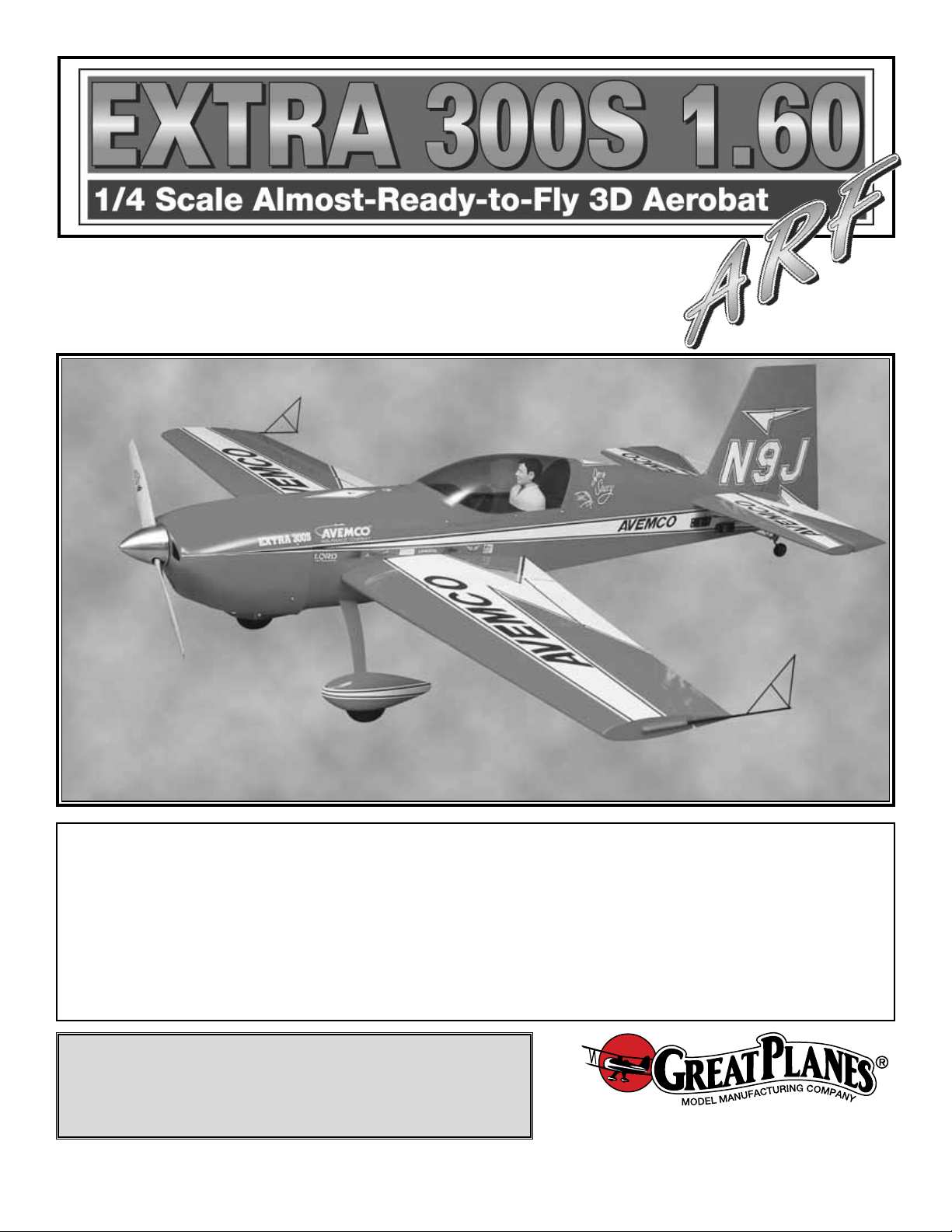
❏❏7. Cut the covering 1/8" [3mm] inside the opening in
the wing for the aileron servo. Use a trim iron to seal the
covering to the inner edges of the opening.
❏❏8. On the top of the wing, cut the covering away from
the hole at the wing center section. This hole is for the
aileron servo wire to come through, into the fuselage.
❏❏9. On the top and bottom of the wing, cut the covering
away from the hole near the wing trailing edge.This hole is
for the wing bolt.
❏❏10. Remove the string from inside of the aileron servo
bay and tape it to the wing. Do not pull the string out of
the wing!
❏ 11. Repeat steps 1-10 for the left wing panel.
❏❏1. Installing the servos in the wing will require the use
of one 12" [305mm] servo extension for each aileron servo.
One Y-harness connector is required and is used to allow
the aileron servos to plug into one slot in your receiver.You
may have a computer radio that allows you to plug the
servos into separate slots and then mix them together
through the radio transmitter .If you choose to mix them with
the radio rather than the Y-harness, refer to the instructions
with your particular brand of radio.
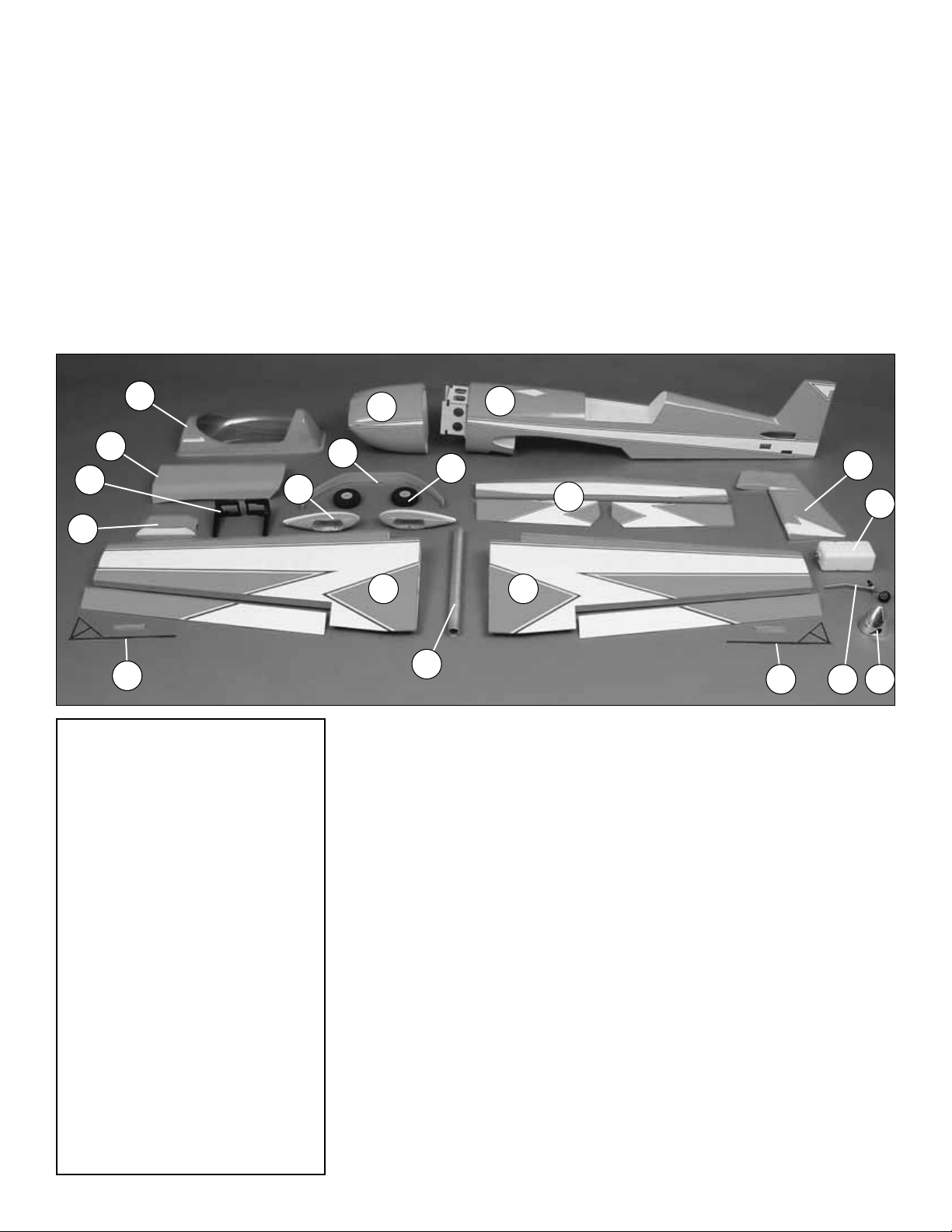
❏❏2. Attach the servo extension to the aileron servo.
Secure the connectors together using a large piece of heat
shrink tubing, tape or other method for securing the
connectors together.
❏❏3.Tie the string from inside the wing to the end of the
servo wire. Pull the servo wire through the wing with the
string.Feed the servo wire out the hole in the top of the wing
center section.Tape the servo wire to the wing to prevent it
from falling back into the wing.
❏❏4.Temporarily position the aileron servo into the servo
bay. Drill a 1/16" [1.6mm] hole through the four mounting
holes of the servo, drilling through the plywood mounting
plate in the wing. Install and remove a servo mounting
screw into each of the four holes. Insert a drop of thin CA
into the holes to harden the wood.After the glue has cured,
install the servo into the servo bay using the hardware that
came with your servo. Center the servo and install a servo
arm as shown.
Install the Aileron servos & pushrods
7
Page 8
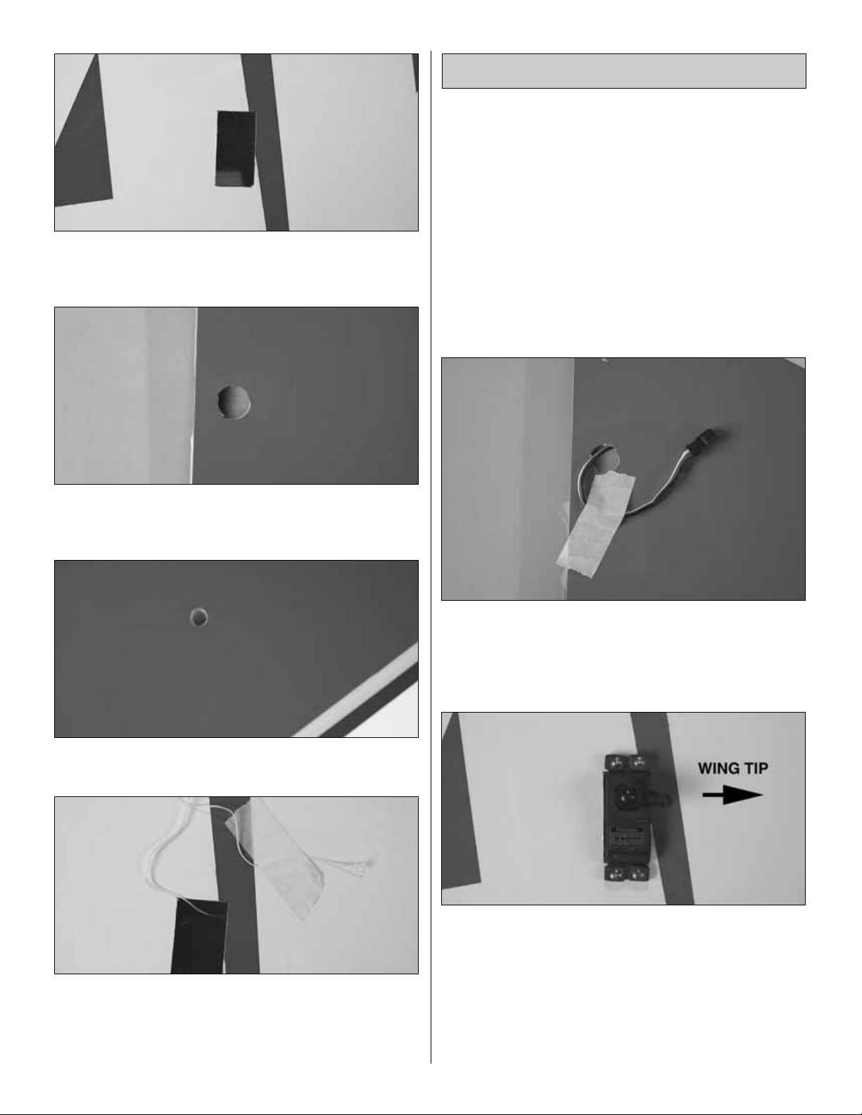
❏❏5. The aileron has a plywood plate for mounting the
control horn. Using a T-pin, lightly puncture the covering to
be sure you are over the plywood plate. Position a large
nylon control horn on the aileron, positioning it as shown
in the sketch and aligning it with the servo.Mark the location
for the screw holes.Dr ill through the marks you made with
a 3/32" [2.4mm] drill bit. (Be sure you are drilling into the
plywood plate mounted in the bottom of the aileron. Drill
through the plate only. Do not drill all the way through the
aileron!) Using a #4 x 5/8" 16mm] sheet metal screw, install
and then remove a screw into each of the holes .Harden the
holes with thin CA.Install the control horn with four #4 x 5/8"
[16mm] sheet metal screws.
❏❏6.Locate a .095" x 12" [.095" x 305mm] pushrod wire
threaded on one end. Screw a 4-40 nut, a silicone clevis
keeper and a threaded metal clevis onto the threaded end
of the wire 20 turns. Tighten the nut against the clevis and
then install the clevis on the aileron control horn.
❏❏7. Be sure the aileron ser vo is centered. Enlarge the
outer most hole in the servo arm with a Hobbico Servo Horn
Drill (or a #48 or 5/64" [2mm] drill bit). Install a 4-40 metal
solder clevis onto the outer most hole in the servo arm.
Center the servo arm and center the aileron. Using the
solder clevis as a guide, mark where to cut the pushrod
wire. Remove the pushrod and clevis from the control horn
and the solder clevis from the servo arm. Solder the clevis
to the pushrod using the “Expert Tip” that follows.
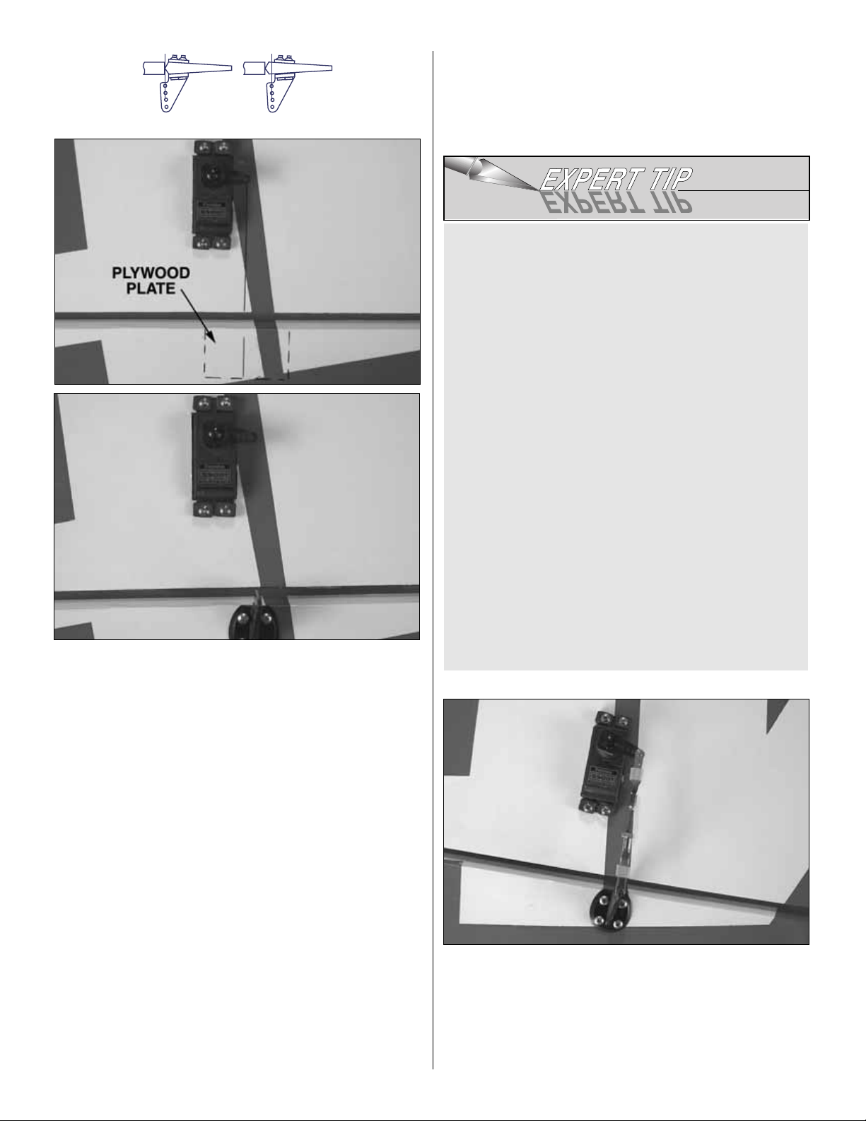
❏❏8. Install a silicone clevis retainer over the solder clevis.
Install the pushrod and clevises to the servo arm and the
control horn. Adjust the linkage until the aileron and the servo
arm are both centered then tighten the nut against the clevis.
❏ 9. Repeat steps 1-8 for the left wing panel
HOW TO SOLDER THE CLEVIS
TO THE PUSHROD
1. Where the pushrod will make contact with the solder
clevis, roughen the wire with 220-grit sandpaper.
2. Use denatured alcohol to remove any oil residue from
the pushrod wire.
Note: Soldering should be done with silver solder not an
electrical solder. Great Planes®has a convenient Silver
solder kit (GPMR8070) that includes flux and solder.
3. Apply a couple of drop of flux to the wire. Slide the
solder clevis onto the wire. Using a small torch or
soldering iron heat the wire, allowing the heated wire
to heat the solder clevis. Apply a small amount of
solder to the joint.When the wire and the clevis are hot
enough the solder will flow into the joint. Avoid using
too much solder causing solder to flow out of the joint
and clump. Use just enough solder to make a good
joint. Allow the wire and clevis to cool.
4. Put a couple of drops of oil onto a rag and wipe the
joint.This will prevent rust from forming on the joint.
Correct Incorrect
8
Page 9
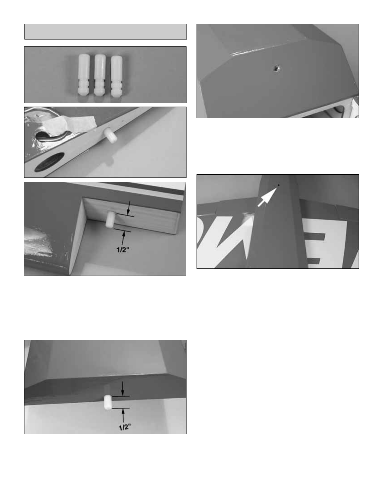
❏ 1. Locate three nylon anti-rotation pins.Using 6-minute
epoxy, glue one into the root on one wing half and one into
each of the holes in the wing’s center section. The pin
should extend approximately 1/2" [13mm]. Clean any
excess epoxy away from the pins with rubbing alcohol
before the epoxy cures.
❏ 2. Using 6-minute epoxy, glue the remaining anti-rotation
pin into the hole in the leading edge of the belly pan.The pin
should extend approximately 1/2" [13mm] from the belly
pan. Clean any excess epoxy away from the pins with
rubbing alcohol before the epoxy cures.
❏ 3. At the rear of the wing saddle you will find a hole. Cut
the covering away from this hole.
❏ 4. Slide the two wing halves together onto the aluminum
joiner tube.Install the wing onto the fuselage with two nylon
wing bolts.
❏5.Cut the covering away from the hole at the bottom rear
of the belly pan.
❏ 6. Insert the pin on the leading edge of the belly pan into
the hole in the former. Push the belly pan onto the wing.
Hold the belly pan in place with a 6-32 x 5/8" [16mm] socket
head cap screw.
Note:The screw threads into a blind nut in the fuselage.Be
sure the threads grab the blind nut before pushing too hard
and dislodging the blind nut.
❏ 7. Remove the wing and belly pan from the fuselage.
Join the Wing
9
Page 10

Note: Because of the wide variety of engine combinations
and the varying weight of the engines you can use for this
airplane, we have designed a convenient place to add
weight to the tail should you find that tail weight is needed.
Weight can be attached to the bottom of the cover with
epoxy. Install the cover now but when you balance the
airplane on page 19, should you need to add weight to the
tail, this is the place to install the weight.
❏ 1. Position the fuselage cover in place on the bottom of
the fuselage. With the cover in place, drill a 1/16" [1.6mm]
hole through the cover and the plywood plate.
❏ 2. Enlarge the holes in the cover only by drilling them out
to 3/32" [2.4mm].
❏ 3. Install then remove a #2 x 3/8" [3mm] sheet metal screw
into the hole in the plywood plate.Put a couple of drops of thin
CA into the hole to harden it and allow the glue to cure.
4. Install the cover onto the fuselage and secure it with two
#2 x 3/8" [3mm] sheet metal screws and two #2 washers.
❏1. Located on the bottom, rear of the fuselage is a plywood
mounting plate. Position the tail wheel assembly so that the
rearward mounting hole is 1/2" [13mm] from the end of the
fuselage.Drill a 5/64" [2mm] hole through each of the mounting
holes in the tail wheel assembly. Mount the tail wheel assembly
to the plate with two #4 x 5/8" [16mm] sheet metal screws.
❏2. Parallel with the axle , file a flat spot f or the steering arm
set screw on the end of the tail wheel wire.
❏ 3. Using the hardware included in the bag with the tail
wheel assembly, install the tail wheel to the axle with two
wheel collars and set screws. Attach the wire to the tail
wheel assembly with a wheel collar and set screw and the
steering arm. Be sure the set screw on the steering ar m is
tightened against the flat spot you filed on the wire.
❏ 4. Locate the aluminum landing gear. Install the gear
onto the bottom of the wing with five 8-32 x 1/2" [13mm]
socket head cap screws. Apply a small drop of thread
locking compound to each bolt before screwing them into
the landing gear.
Install the Tail Gear & Landing Gear
Install the Fuselage Cover
ASSEMBLE THE FUSELA GE
10
Page 11

❏5.Glue the landing gear cover in place with RTV silicone.
❏❏6. On one of the wheel pants place masking tape on
the side of the pant. Mark the center of the wheel opening
on the pant. On that centerline make a crossing line 1/2"
[13mm] from the bottom of the pant. Where the two lines
intersect make a 1/2" [13mm] hole in the side of the pant.
Do the same for the other wheel pant.Be sure to do this on
the opposite side making a right and left wheel pant.
❏❏7.Where you have made the hole, sand the inside of the
wheel pant with 220-grit sandpaper.Then wipe the area clean
with rubbing alcohol. Glue one of the plywood wheel pant
mounting plates inside the pant with 6-minute epoxy mixed
with micro balloons. (The micro balloons will help thicken the
epoxy and prevent it from running excessively.) Clamp the
plate to the inside of the pant until the glue has cured.
❏❏8. Install the axle and nut on each side of the
landing gear
❏❏9.Using a high-speed motor tool and cut-off wheel, cut
the 2" [51mm] axle to a length of 1-7/8" [47mm].
❏❏10.Temporarily slide the wheel pant and a wheel onto
the axle.Position the wheel pant so that the back of the pant
is 1" [25mm] from the top of your work bench. On the
aluminum landing gear there are two small holes.With the
wheel pant properly positioned mark the hole locations onto
the wheel pant.
❏❏11. Remove the wheel and pant from the axle. Drill a
1/16" [1.6mm] hole though the marks you made on the
wheel pant. Install and then remove a #2 x 3/8" [9.5mm]
screw into the holes. Apply a drop of thin CA into the holes
and allow the glue to cure.
❏❏12.Install a 6-32 x 1/4" [6mm] socket head cap screw into
two 5-32" [4mm] wheel collars. Install the wheel pant and the
wheel with a wheel collar on each side of the wheel, onto the
axle. Tighten the wheel pant to the aluminum landing gear by
installing a #2 x 3/8" [9.5mm] screw into the holes in the landing
gear and the holes you drilled in the wheel pant.
11
Page 12

❏ 1. Cut the covering from the openings at the rear of the
fuselage for the horizontal stab.
❏ 2. Install the wing onto the fuselage.There is no need to
install the belly pan.
❏ 3. Install the horizontal stab into the back of the fuselage.
Center the stab, making sure the distance from center is equal
on both sides of the stab. Stand back 15-20 ft. [5-6m] and
check to be sure the stab is parallel to the wing.Adjust the stab
saddle as needed until the stab and wing are parallel.
❏ 4. Measure the distance from the tip of each wing to the
tip of the stab.Adjust the stab until the distance from the tip
of the stab to the tip of the wing is equal on both sides.
❏5.Use a felt tip marker to mark the outline of the fuselage
onto the top and bottom of the stab.
❏6. Remove the stab from the fuse .Use a sharp #11 hobby
knife or use the following Expert Tip to cut the covering
1/16" [1.6 mm] inside of the lines you marked. Use care to
cut only into the covering and not into the wood.
❏7.Use 30 minute epoxy to glue the stab into the fuse.For the
most strength, apply epoxy to both sides of the stab and inside
the fuse where the stab fits. Slide the stab into position. Wipe
away residual epoxy with a paper towel and alcohol. Do not
disturb the model until the epoxy has fully hardened.
❏ 8. Cut nine CA hinges for the elevators and rudder just as
you did for the ailerons.Install the CA hinges on the elevators
and the rudder using the same technique used on the ailerons.
Apply six drops of thin CA on each side of each CA hinge.
Use a straightedge to guide the soldering iron at a rate
that will just melt the covering and not burn into the
wood. The hotter the soldering iron, the faster it must
travel to melt a fine cut. Peel off the covering.
HOW TO CUT COVERING FROM BALSA
Use a soldering iron to cut the covering from the stab.
The tip of the soldering iron doesn't have to be sharp, but
a fine tip does work best. Allow the iron to heat fully.
Install the Stab, Elevator & Rudder
12
BB
B = BA = A
AA
Page 13

❏ 1. On left side of the fuselage you will find two servo
openings. On the right side you will find one. Cut the
covering from the servo openings.
❏❏2. Install your left elevator servo into the forward servo
compartment on the left side of the fuselage. Drill a 1/16"
[1.6mm] hole through each of the mounting holes in the servo.
Remove the servo. Inser t and then remove a servo mounting
screw into each of the holes you have drilled. Put a drop of thin
CA into each hole and allow the glue to cure. The servo will
require a 24" [610mm] extension to reach the radio
compartment. Install the extension onto the servo and secure it
using the same method used on the ailerons. Install the servo
in the compartment with the hardware provided with your servo.
Center the servo.Then install a servo arm onto the ser vo.The
servo arm should be pointing towards the bottom of the stab.
❏ 3. Repeat step two for the right side of the fuselage.
❏❏4. Look closely on the bottom of the left elevator and
you will notice a plywood plate visible under the covering.
The control horn must be mounted to this plate. Place a
control horn in position on the elevator in line with the servo
arm. Mark the location of the four mounting holes. Drill a
5/64" [2mm] hole through each of the marks, being careful
not to drill through the top of the elevator. Inser t and then
remove a #4 x 5/8" [16mm] screw into each of the holes y ou
have drilled. Put a drop of thin CA into each hole and allow
the glue to cure. Install the control horn with four #4 x 1/2"
[13mm] screws.
❏❏5. (Referring to the photo at step 7 will help you
understand the following step .) Install a 4-40 nut, silicone cle vis
keeper and a threaded 4-40 aluminum clevis onto the threaded
end of a .095 x 12" [2.4 x 305mm] pushrod. Tighten the nut
against the clevis.Install the clevis in the second hole from the
end of elevator control horn. Install a 4-40 solder clevis in the
last hole on the servo arm. Center the elevator and mark the
wire where it needs to be cut to be the correct length to fit into
the solder clevis.Remove the clevises from the horns.Then cut
the wire on the mark you made.
❏❏6. Solder the wire to the clevis using the technique
described for the ailerons.
❏❏7. Install the completed pushrod to the elevator and
servo, securing the clevis with the silicone clevis keeper.
Note:If you plan to use your Extra 300S primarily for 3D flying,
read the optional rudder servo installation on page 20.
❏ 8. Repeat steps 4-7 for the right side of the fuselage.
❏ 9. Install the r udder servo in the remaining opening on the
left side of the fuselage. The rudder servo should be a
minimum torque rating of 87 oz. in. Use the same installation
method and pushrod technique you used for the elevator.
Install the Elevator & Rudder
Pushrods & Servos
13
Page 14

❏ 10. A 2-56 clevis will be used to attach the tail wheel
steering arm to the rudder servo but the steering arm is
slightly too thick for the clevis. Sand off 1/32" [.8mm] from
the face of the steering arm, allowing a 2-56 clevis to fit
easily over the arm.
❏ 11. Examine the photograph to help in making the tail
wheel steering control arm. Remove the clevis from the
rudder control arm. Then remove the 4-40 threaded clevis
and 4-40 nut from the pushrod wire.Slide a #4 washer onto
the rudder pushrod followed by a 1" piece of silicone fuel
tubing, the nylon steering horn, another piece of 1" silicone
fuel tubing and another #4 washer. Reinstall the 4-40 nut
onto the pushrod followed by the 4-40 aluminum clevis.
Adjust the rudder clevis and then tighten the 4-40 nut
against the clevis.
❏12.Install a 2-56 nut completely onto the threaded end of the
.074 x 6" [1.9 x 152mm] wire. Cut 1/2" [13mm] off of the
threaded end of the wire. Unscrew the nut from the threads;
this will clean up the threads allowing the 2-56 clevis to easily
thread onto the wire. Re-install the nut followed by a 2-56
aluminum threaded clevis. Bend the wire as shown in the
photograph in step #11. Install the wire and clevis to the tail
wheel steering arm. Install a 2-56 solder clevis onto the nylon
steering horn. Center the tail wheel with the rudder. Cut the
non-threaded end of the wire to length to fit into the solder
clevis. Remove the wire and clevises from the model. Solder
the 2-56 solder clevis to the end of the wire using the same
technique used on the pushrod wires.Install the wire to the tail
wheel and the nylon steering horn. Minor adjustments to the
steering arm can be made at the threaded clevis. Once
adjusted properly, tighten the nut against the clevis.
❏ 1. Using a fine tip marker, extend the reference lines on
the firewall. Tape the engine mounting pattern located on
page 27 to the firewall. Align the reference lines on the
pattern with the lines on the firewall.Drill through the firewall
on the reference holes with a 3/16" [4.8mm] bit.
❏ 2. Install the engine mount onto the firewall with four #8 x
1-1/4" [32mm] socket head cap screws , #8 flat w ashers and #8
lock washers.When installing the mount be sure you orient it as
shown so that the engine can be mounted on its side.
❏ 3. Mark the location of the engine mount holes on the
mount. Drill a 9/64" [4mm] hole through each of these
marks. Run an 8/32 tap through each hole. Mount the
engine to the mount with four #8 x 1" [25mm] socket head
cap screws, #8 flat washers and #8 loc k washers.Mount the
engine so that the distance from the front of the firewall to
the front of the engine thrust washer is 6-1/4" [159mm].
Install the Engine, Fuel Tank
& Throttle Servo
14
Page 15

❏ 4. Assemble the fuel tank as shown in the sketch.When
tightening the center screw be sure not to over tighten it.You
just want it snug enough to pull the rubber stopper tight
against the tank.
❏ 5. Install the tank into the fuselage with the neck of the
tank through the firewall. Hold the tank in place inside the
fuselage by gluing a balsa stick (not included) across the
back of the tank.
❏6. Install silicone fuel tubing, (not included in the kit) onto
the aluminum tubes from the fuel tank.The line with the fuel
clunk will feed to the fuel inlet at the needle valve and the
other will attach to the pressure tap on the muffler. For our
installation we chose to use an external fill valve. If you
choose to do this, follow the instructions with your particular
brand of fuel valve. Should you choose not to install a fuel
filler valve you can fill the fuel tank by removing the fuel line
to the carburetor and filling through it. Depending how you
cut out the cowling to accommodate the engine, the cowling
may make it difficult to access the carburetor.You can also
install a third line to the tank and use it for filling the tank.
The method you use is your choice but make your decision
before moving onto the installation of the fuel tank.
❏7. Drill a 13/64" [5.2mm] hole in the firewall in line with the
throttle arm. Locate the 11-3/4" gray plastic tube. Roughen
one end of the tube with 220-grit sandpaper. Insert the unsanded end of the tube into the hole you have drilled.Glue
the tube flush to the firewall. Install a nylon clevis and
silicone clevis keeper onto the threaded end of the .074 x
17-1/2" [445mm] wire approximately 20 turns. Insert the
wire throttle pushrod into the plastic tube. The pushrod will
need to be bent to work with your particular engine and
muffler. When bending the pushrod wire be sure that the
wire does not make contact with the engine or muffler .Metal
to metal contact can set up radio interference. Be sure the
throttle pushrod operates smoothly after all of the bends
have been made.
❏ 8. Attach the nylon clevis to the throttle arm. Install the
throttle servo into the servo tray inside the fuselage.Mount
it using the same method used on the servos you have
already installed. Install a screw-lock connector onto the
servo arm securing it to the arm with the nylon retainer.
Insert the wire into the hole in the screw-lock connector and
secure it with a 6-32 x 1/8" [3mm] socket head cap screw.
❏ 1. Locate four hardwood cowl mounting blocks.
Position one b lock just abo ve the trim stripe on the fuselage.
Using 6-minute epoxy glue one block to the firewall, flush
with the fuselage. Glue the second block to the firewall,
locating it approximately 4-1/2" [114mm] below the other
block.Repeat this on the other side of the fuselage.
INST ALL THE COWL
TOP OF FUSELAGE
P
15
SILICONE FUEL
LINE
FUEL TUBE
FUEL CLUNK
PRESSURE TA
TO MUFFLER
TO NEEDLE
VALVE
FIREWALL
Page 16

❏ 2. Make a mark in the center of each block. Using a felt
tip marker draw a 3" [76mm] line back onto the fuselage .Do
this on each of the four mounting blocks.
❏ 3. Locate one 1/8" [3mm] balsa disk, one 1/8" [3mm]
balsa ring and two 1/8" [3mm] balsa rings. Glue the 1/8"
[3mm] balsa ring onto the 1/8" [3mm] balsa disk, carefully
aligning the outer edges. Glue the two 1/8" [3mm] rings
together forming a 1/4" [6mm] ring. Glue the 1/4" [6mm]
balsa ring onto the 1/8" [3mm] balsa ring, carefully aligning
the inside edges.
❏4.These disks will now be an alignment tool for centering the
cowl.The hole in the center of the plywood plate is designed to
fit the crankshaft of an O.S.®1.20. If you are using a larger
engine than the 1.20, the crankshaft is most likely larger. Use
a propeller reamer to make the hole in the center of the
plywood plate fit your particular engine crankshaft.
❏ 5. Install the cowl over the engine. Slide the alignment
tool over the crankshaft and firmly against the engine thrust
washer. Tighten the prop nut and washer against the
plywood plate. With the alignment tool tight to the engine
thrust washer, slide the opening in the cowl over the
alignment tool.When the front of the cowl is tight against the
alignment tool the cowl is properly centered and is
positioned for the proper clearance between the spinner
back plate and the cowl.
❏ 6. Keeping the cowl tight against the alignment tool,
position the cowl so the paint lines on the cowl and fuselage
are in alignment with each other.When properly positioned,
tape the cowl in place to the fuselage.
❏ 7. Measure 3" [76mm] back to the cowl from the end of
the reference lines you made. Drill a 3/32" [2.4mm] hole
through the cowl and into the cowl mounting block. Install a
#4 x 1/2" [13mm] sheet metal screw and a #4 flat washer
into each of the holes drilled. Remove the alignment tool
after the cowl has been secured with the four screws.
❏8.Remove the cowl.Put a couple of drops of thin CA into
the holes in the mounting blocks to harden the threads.
❏ 9. Cut a piece of card stock 2" x 10" [51 x 254mm].Tape
it to the side of the fuselage in line with the glow plug. Mark
the location of the glow plug on the card stock.Re-install the
cowling so the card stock is outside of the cowl.Transfer the
glow plug location to the cowl and cut the hole for the glow
plug using a high speed rotary tool. Use this same
technique for locating the needle valve.
16
Page 17

❏ 10. Remove the cowl and install the muffler for your
engine.We used the Bisson Pitts muffler (BISG4116) for the
O.S. 160. Make the appropriate cut out in the cowl to
accommodate your choice of muffler.
❏ 11. Once you have completed cutting the cowl, reinstall
the cowl and install the prop and spinner.
❏ 1. Cut the 10" [254mm] piece of Velcro
®
into two 5"
[127mm] lengths.
❏ 2. Install the receiver and battery as shown. Install a
piece of foam under the battery and receiver .Use the Velcro
to hold them in place. Plug all of the servos into the proper
channel in the receiver. Install a switch and charge jack into
the fuselage.Plug the battery into the switch and secure the
connector with a piece of heat shrink tubing, tape or other
method of securing the connectors to prevent them from
accidentally separating.
❏3.Drill a hole in the bottom of the fuselage approximately
3/4" [19mm] behind the wing. The hole should be slightly
under-sized from the outer dimension of the silicone you
choose to use. Install a 3/4" [19mm] length of silicone fuel
tubing (not included) into the hole.
❏ 4. From a servo horn, make a strain relief as shown.
Install the receiver wire through the silicone tube you
installed in the fuselage.Secure the end of the antenna wire
around the tail wheel with a rubber band.
RADIO INSTALLATION
17
Page 18

❏ 1. Before installing the canopy you may wish to paint the
cockpit area and install a pilot. Once the paint has dried
install the instrument panel decal.
❏ 2. Cut the canopy on the cut lines. Look inside the
cockpit. You will see that there is a plywood rail on each
side. This rail also extends into the fuselage. If you look
inside of the fuselage you can see this rail. This rail will
provide a secure mount for screwing the canopy in place.If
you prefer, you can glue the canopy in place.
❏ 3. Position the canopy on the fuselage. Drill three 1/16"
[1.6mm] holes through the canopy and fuselage on both
sides of the canopy. Before you drill be sure you are
drilling over the mounting rails! Remove the canopy and
drill a 3/32" [2.4mm] hole through each of the holes in the
canopy. Install and then remove a #2 x 3/8" [9.5mm] sheet
metal screw into each of the canopy mounting holes in the
fuselage. Apply a drop of thin CA into the holes to harden
the threads in the plywood rails. Install the canopy using
three #2 x 3/8" [9.5mm] sheet metal screws and three #2
washers on each side of the canopy.
❏ 4. Position the ABS plastic tube holders on the wing tip
as shown. Trace the outline of the tube holders onto the
wingtip. Cut away a strip of the covering just inside the
reference lines.Glue the tube holders in place with 6-minute
epoxy. Do this for both wing tips.
❏ 5. Slide the aerobatic sighting reference guide tube into
the tube holder when you wish to display the airplane with
them on.
❏ 1. Use scissors or a shar p hobby knife to cut the decals
from the sheet.
❏ 2. Be certain the model is clean and free from oily
fingerprints and dust. Prepare a dishpan or small bucket with
a mixture of liquid dish soap and warm water—about one
teaspoon of soap per gallon of water.Submerse the decal in
the soap and water and peel off the paper backing.
Note: Even though the decals have a “sticky-bac k”and are not
the water transfer type , submersing them in soap & water allows
accurate positioning and reduces air bubbles underneath.
❏3.Position the decal on the model where desired.Holding the
decal down, use a paper towel to wipe aw ay most of the water.
❏ 4. Use a piece of soft balsa or something similar to
squeegee the remaining water from under the decal. Apply
the rest of the decals the same way.
❏ 1. Turn on the transmitter and receiver and center the
trims. If necessary, remove the servo arms from the servos
and reposition them so they are centered. Reinstall the
screws that hold on the servo arms.
❏ 2. With the transmitter and receiver still on, check all the
control surfaces to see if they are centered.If necessary, adjust
the clevises on the pushrods to center the control surfaces.
Check the Control Directions
PREP ARE T O FL Y
Apply the Decals
We have included the option of installing an “aerobatic
sighting reference guide tube” on each of the wing tips.
These are commonly found on most aerobatic
airplanes. These are not meant to be permanently
mounted and left on during flight (though you could if
you wish). They are for static display and are easily
removable before flight.
FINISHING TOUCHES
18
Page 19

❏3. Make certain that the control surfaces and the carburetor
respond in the correct direction as shown in the diagram.If any
of the controls respond in the wrong direction, use the servo
reversing in the transmitter to reverse the servos connected to
those controls. Be certain the control surfaces have remained
centered. Adjust if necessary.
Use a Great Planes AccuThrow (or a ruler) to accurately
measure and set the control throw of each control surface
as indicated in the chart that follows. If your radio does not
have dual rates, we recommend setting the throws at the
low rate setting.
NOTE:The throws are measured at the widest part of the
elevators, rudder and ailerons.
At this stage the model should be in ready-to-fly condition
with all of the systems in place including the engine,
landing gear, covering and paint, and the radio system.
❏ 1. Use a felt-tip pen or 1/8"-wide tape to accurately mark
the C.G. on the bottom of the wing on both sides of the
fuselage.The C.G. is located 5-1/2" [140mm] back from the
leading edge of the wing.
This is where your model should balance for the first
flights.Later, you may wish to experiment by shifting the
C.G. up to 3/4" [19mm] forward or 1/2" [13mm] back to
change the flying characteristics. Moving the C.G.
forward may improve the smoothness and stability, but
the model may then require more speed for takeoff and
make it more difficult to slow for landing. Moving the
C.G. aft makes the model more maneuverable, but
could also cause it to become too difficult to control. In
any case, start at the recommended balance point
and do not at any time balance the model outside the
specified range.
More than any other factor, the C.G. (balance point) can
have the greatest effect on how a model flies, and may
determine whether or not your first flight will be successful.
If you value this model and wish to enjoy it for many flights,
DO NOT OVERLOOK THIS IMPORTANT PROCEDURE.
A model that is not properly balanced will be unstable and
possibly unflyable.
Balance the Model (C.G.)
IMPORTANT: The Extra 300S 1.60 ARF has been
extensively flown and tested to arrive at the throws at
which it flies best.Flying your model at these throws will
provide you with the greatest chance for successful first
flights.If, after you have become accustomed to the w a y
the Extra 300S flies, you would like to change the
throws to suit your taste, that is fine.However, too much
control throw could make the model difficult to control,
so remember, “more is not always better.”
These are the recommended control surface throws:
High Rate Low Rate
ELEVATOR: 1/2" up [12.7mm] 3/8" up [9.5mm]
1/2" down [12.7mm] 3/8" down [9.5mm]
RUDDER: 4" right [102mm] 2-1/2" right [64mm]
4" left [102mm] 2-1/2" left [64mm]
AILERONS: 1" up [25.4mm] 5/8" up [15.9mm]
1" down [25.4mm] 5/8" down [15.9mm]
Set the Control Throws
4-CHANNEL
19
TRANSMITTER
4-CHANNEL
TRANSMITTER
4-CHANNEL
TRANSMITTER
4-CHANNEL
TRANSMITTER
Page 20

❏ 2.With the wing attached to the fuselage, all parts of the
model installed (ready to fly) and an empty fuel tank, place
the model upside-down on a Great Planes CG Machine, or
lift it upside-down at the balance point you marked.
❏ 3. If the tail drops, the model is “tail heavy” and the
battery pack and/or receiver must be shifted forward or
weight must be added to the nose to balance. If the nose
drops, the model is “nose heavy” and the battery pack
and/or receiver must be shifted aft or weight must be added
to the tail to balance. If possible, relocate the battery pack
and receiver to minimize or eliminate any additional ballast
required. If additional weight is required, nose weight may
be easily added by using a “spinner weight”(GPMQ4645 for
the 1 oz. weight, or GPMQ4646 for the 2 oz. weight). If
spinner weight is not practical or is not enough, use Great
Planes (GPMQ4485) “stick-on” lead. A good place to add
stick-on nose weight is to the firewall (don’t attach weight to
the cowl—it is not intended to support weight). Begin by
placing incrementally increasing amounts of weight on the
bottom of the fuse over the firew all until the model balances.
Once you have determined the amount of weight required,
it can be permanently attached. If required, tail weight may
be added inside of the hatch on the bottom of the fuse and
gluing it permanently inside.
Note: Do not rely upon the adhesive on the back of the lead
weight to permanently hold it in place. Over time, fuel and
exhaust residue may soften the adhesive and cause the
weight to fall off. Use #2 sheet metal screws, RTV silicone
or epoxy to permanently hold the weight in place.
❏ 4. IMPORTANT: If you found it necessary to add any
weight, recheck the C.G.after the weight has been installed.
❏ 1. With the wing level, have an assistant help you lift the
model by the engine propeller shaft and the bottom of the
fuse under the TE of the fin.Do this several times.
❏2.If one wing always drops when you lift the model, it means
that side is heavy. Balance the airplane by adding weight to the
other wing tip. An airplane that has been laterally balanced
will track better in loops and other maneuvers.
The Great Planes Extra 300S 1.60 ARF will perform 3-D
aerobatics easily if you use the largest engines
recommended within the engine range. If you setup your
airplane to do 3D maneuvers, you will need to be throttle
conscious; that is, never apply full throttle on straight and
level flying or in dives to prevent flutter.
❏ 1. Because 3D flying requires very large control throws
you need to mount the servo arm so that it is pointing
towards the bottom of the fuselage instead of towards the
stab as shown on page 13 of the instruction manual. This
also requires that you mount the control horn at the very
bottom of the rudder. The standard aerobatic linkage set up
is a very straight linkage between the servo and the rudder
but there is a chance that at the extreme ends of the
3D Rudder Servo/Control Horn
Installation
ELEVATOR: 3/4" up 3/4" down
[19.1mm] [19.1mm]
RUDDER: 6-1/2" right 6-1/2" left
[165.1mm] [165.1mm]
AILERONS: 2" up 2" down
[51mm] [51mm]
3D Control Throws
3-D PERFORMANCE SETTINGS
Balance the Model Laterally
5-1/2"
20
[140mm]
Page 21

recommended 3D control throws you could have a conflict
between the elevator and rudder servos and servo arms. If
your primary flying will be 3D we recommend you set the
linkage as shown for 3D flight.
Note: When using the extreme throws of 3D flight you
need to make the tail wheel control arm longer so that the
mechanical linkage from the rudder servo to the rudder will
not limit the distance the rudder can travel.
❏ 2. Cut one of the Dubro Super Strength Arms as shown.
❏3.Glue the cut servo arm to the arm on the tail wheel with CA.
❏ 4. Install a small screw though both horns.
Complete the assembly following the instructions on page
14 step 10 of the instruction manual
Larger than stock servo arms are highly recommended for
getting the 3D throws for the Extra 300S ARF.Do not move
the pushrods in on the control horns to get the increased
throw, as doing that intensifies any play in the system.
Dubro Super Strength Arms sets (DUBM6670) were used
on the test models.
The large control throws require servos with great
centering. The digital servos are second to none in this
department. Digital servos such as the Futaba S9250
(FUTM0220) should be used on all control surfaces of this
airplane for optimum performance. The test models were
also flown successfully in 3D mode with analog Futaba
S9304 (FUTM0095) servos.
COMPUTER RADIOS
As you prepare to fly your Extra 300S 1.60 ARF for the
first time, there are a few features on computer radios we’d
like to mention.There are many others, of course, but these
are commonly used features on most computer radios. If
you are using a non-computerized radio, this information
may still be of interest to you for future installations.
ATV or Travel Volume:
ATV is a wonderful feature of
computer radios which allows you to make minor
adjustments to how far a servo travels at its extremes.
For example, you install the throttle pushrod, and it’s
almost perfect, except you have some binding at wide
open. Instead of struggling with the clevises to try to
keep full throttle but not have the binding, you can turn
down the ATV slightly until the binding is gone.Why only
adjust ATV slightly? Control linkages are really just a
lesson in leverage. The less distance the servo is
moving for a given throw at the surface, the less
leverage you have given the servo to do the job. Thus
the lower you set the ATV the less power you are leaving
for the servo to apply to the surface .Additionally , a servo
has only so many points within its range of motion. By
cutting its range in half, you’ve also diminished the
precision of the servo by 50%.Because of both of these
issues, we strongly recommend setting the high rates as
close as possible to 100% on the ATV.
Dual Rates:
Setting dual rates helps make your model
easier to fly in a variety of situations. For example, an
expert pilot who wants to do torque rolls will need a
large amount of control throw. However, he does not
want that same huge volume of throw when he is trying
3D Servos
3D Servo Arms
21
Page 22

No matter if you fly at an AMA sanctioned R/C club site or if you
fly somewhere on your own, you should always have your
name, address, telephone number and AMA number on or
inside your model.It is required at all AMA R/C club flying sites
and AMA sanctioned flying events .Fill out the identification tag
on the decal sheet and place it on or inside your model.
Follow the battery charging instructions that came with your
radio control system to charge the batteries. You should
always charge your transmitter and receiver batteries the
night before you go flying, and at other times as
recommended by the radio manufacturer.
NOTE: Checking the condition of your receiver battery pack is
highly recommended. All batter y packs, whether it’s a trusty
pack you’ve just taken out of another model, or a new battery
pack you just purchased, should be cycled, noting the discharge
capacity .Oftentimes, a weak battery pack can be identified (and
a valuable model saved!) by comparing its actual capacity to its
rated capacity. Refer to the instructions and recommendations
that come with your cycler. If you don’t own a battery cycler,
perhaps you can have a friend cycle your pack and note the
capacity for you.
Carefully balance your propeller and spare propellers before
you fly. An unbalanced prop can be the single most significant
cause of vibration that can damage your model. Not only will
engine mounting screws and bolts loosen, possibly with
disastrous effect, but vibration may also damage your radio
receiver and battery .Vibration can also cause your fuel to foam,
which will, in turn, cause your engine to run hot or quit. We use
a Top Flite Precision Magnetic Prop Balancer™(TOPQ5700) in
the workshop and keep a Great Planes Fingertip Prop
Balancer (GPMQ5000) in our flight box.
If the engine is new, follow the engine manufacturer’s
instructions to break-in the engine. After break-in,
confirm that the engine idles reliably, transitions smoothly
and rapidly to full power and maintains full power—
indefinitely. After you run the engine on the model, inspect
the model closely to make sure all screws remained tight,
the hinges are secure, the prop is secure and all pushrods
and connectors are secure.
Ground check the operational range of your r adio before the first
flight of the day. With the transmitter antenna collapsed and the
receiver and transmitter on, you should be able to walk at least
100 feet away from the model and still have control. Have an
assistant stand by your model and, while you w ork the controls,
tell you what the control surfaces are doing. Repeat this test
with the engine running at various speeds with an assistant
holding the model, using hand signals to show you what is
happening. If the control surfaces do not respond correctly, do
not fly! Find and correct the problem first. Look for loose servo
connections or broken wires, corroded wires on old servo
connectors, poor solder joints in your battery pack or a defectiv e
cell, or a damaged receiver crystal from a previous crash.
Range Check
Ground Check
Balance Propellers
Charge the Batteries
Identify Y our Model
PREFLIGHT
to do smooth loops or slow rolls. Low rates give your
model a soft feel, with aggressive responsiveness just a
flip of a switch away.
Exponential, the best of both rates:
Exponential is a
feature which modelers tend to either love or hate. The
benefits of exponential are that they make the elevator,
for example, feel like it is on low rates when you are
moving the stick near center; however, when you get
farther from center the model gets progressively more
responsive.The reason this is helpful is that it allows you
to make soft, minor adjustments when small corrections
are needed, but still allows you sufficient throw to make
major changes at full stick. For example, you can
smoothly level the wings while flying along straight and
level without over-controlling, yet still have enough
aileron throw at full stick to complete a one-second roll.
Idle Down and Throttle Kill:
Idle down allows you to
have a switch set for a high idle, ideal for most
aerobatics where you have little or no risk of dead
sticking, as well as a lower idle setting for, say, landings,
taxiing, and minimum throttle maneuvers such as spins.
The throttle kill setting on most computer radios will idle
your engine down whatever percent you set it so that
your engine will shut off when the switch is thrown and
the throttle stick is in the idle position. This is an
excellent safety feature to shut off your engine in
emergency situations.
22
Page 23

Keep all engine fuel in a safe place, away from high heat,
sparks or flames, as fuel is very flammable. Do not smoke
near the engine or fuel; and remember that engine exhaust
gives off a great deal of deadly carbon monoxide .Therefore
do not run the engine in a closed room or garage.
Get help from an experienced pilot when learning to
operate engines.
Use safety glasses when starting or running engines.
Do not run the engine in an area of loose gravel or sand;
the propeller may throw such material in your face or eyes.
Keep your face and body as well as all spectators away
from the plane of rotation of the propeller as you start and
run the engine.
Keep these items away from the prop: loose clothing, shirt
sleeves, ties, scarfs, long hair or loose objects such as
pencils or screwdrivers that may fall out of shirt or jacket
pockets into the prop.
Use a “chicken stick” or electric star ter to start the engine.
Do not use your fingers to flip the propeller. Make certain
the glow plug clip or connector is secure so that it will not
pop off or otherwise get into the running propeller.
Make all engine adjustments from behind the rotating propeller .
The engine gets hot! Do not touch it during or right after
operation.Make sure fuel lines are in good condition so fuel
will not leak onto a hot engine, causing a fire.
To stop a glow engine, cut off the fuel supply by closing off
the fuel line or following the engine manufacturer’s
recommendations. Do not use hands, fingers or any other
body part to try to stop the engine. To stop a gasoline
powered engine an on/off switch should be connected to
the engine coil. Do not throw anything into the propeller of
a running engine.
Read and abide by the following Academy of Model
Aeronautics Official Safety Code:
GENERAL
1. I will not fly my model aircraft in competition or in the
presence of spectators until it has been proven to be airworthy
by having been previously successfully flight tested.
2. I will not fly my model aircraft higher than approximately
400 feet within 3 miles of an airport without notifying the
airpor t operator. I will give right of way to and avoid flying in
the proximity of full scale aircraft. Where necessary, an
observer shall be utilized to supervise flying to avoid having
models fly in the proximity of full-scale aircraft.
3.Where established, I will abide by the safety rules for the
flying site I use and I will not willfully and deliberately fly my
models in a careless, reckless and/or dangerous manner.
7.I will not fly my model unless it is identified with my name
and address or AMA number, on or in the model.
RADIO CONTROL
1. I will have completed a successful radio equipment ground
check before the first flight of a new or repaired model.
2. I will not fly my model aircraft in the presence of
spectators until I become a qualified flyer, unless assisted
by an experienced helper.
3. I will perform my initial turn after takeoff away from the
pit, spectator and parking areas and I will not thereafter
perform maneuvers, flights of any sort or landing
approaches over a pit, spectator or parking area.
4. I will operate my model using only radio control
frequencies currently allowed by the Federal
Communications Commission.
❏ 1. Fuelproof all areas exposed to fuel or exhaust
residue such as the wing saddle area or the engine
spacer if needed.
❏ 2. Check the C.G. according to the measurements
provided in the manual.
❏ 3. Be certain the battery and receiver are securely
mounted in the fuse.Simply stuffing them into place
with foam rubber is not sufficient.
❏ 4 Extend your receiver antenna and make sure it has
a strain relief inside the fuselage to keep tension off
the solder joint inside the receiver.
❏ 5. Balance your model
laterally
as explained in
the instructions.
During the last few moments of preparation your mind
may be elsewhere anticipating the excitement of the first
flight. Because of this, you may be more likely to overlook
certain checks and procedures that should be performed
before the model is flown.To help avoid this, a check list
is provided to make sure these important areas are not
overlooked. Many are covered in the instruction manual,
so where appropriate, and refer to the manual for
complete instructions. Be sure to check the items off as
they are completed.
CHECK LIST
AMA SAFETY CODE (excerpts)
Failure to follow these safety precautions may
result in severe injury to yourself and others.
ENGINE SAFETY PRECAUTIONS
23
Page 24

❏ 6. Use thread locking compound to secure critical
fasteners such as the screws that hold the
carburetor arm (if applicable), Screw-Lock pushrod
connectors, etc.
❏ 7. Add a drop of oil to the axles so the wheels will
turn freely.
❏ 8. Make sure all hinges are securely glued in place.
❏ 9. Reinforce holes for wood screws with thin CA
where appropriate (servo mounting screws, cowl
mounting screws, etc.).
❏ 10. Confirm that all controls operate in the correct
direction and the throws are set up according to
the manual.
❏ 11. Make sure there are silicone retainers on all the
clevises and that all servo arms are secured to the
servos with the screws included with your radio.
❏ 12. Secure the connections between servo wires and
Y-connectors or servo extensions, and the
connection between your battery pack and the
on/off switch with vinyl tape, heat shrink tubing or
special clips suitable for that purpose.
❏ 13. Make sure any servo extension cords y ou ma y hav e
used do not interfere with other systems (servo
arms, pushrods, etc.).
❏ 14. Secure the pressure tap (if used) to the muffler with
high temp RTV silicone, thread locking compound
or J.B.Weld.
❏ 15. Make sure the fuel lines are connected and are
not kinked.
❏ 16. Balance your propeller (and spare propellers).
❏ 17. Tighten the propeller nut and spinner.
❏ 18. Place your name, address, AMA number and
telephone number on or inside your model.
❏ 19. Cycle your receiver battery pack (if necessary) and
make sure it is fully charged.
❏ 20. If you wish to photograph your model, do so before
your first flight.
❏ 21. Range check y our radio when you get to the flying
field.
The Extra 300S 1.60 ARF is a great-flying model that flies
smoothly and predictably. It does not, howev er, possess the
self-recovery characteristics of a primary R/C trainer and
should be flown only by experienced R/C pilots.
Fuel Mixture Adjustments
A fully cowled engine may run at a higher temperature than an
un-cowled engine.For this reason, the fuel mixture should be
richened so the engine runs at about 200 rpm below peak
speed.By running the engine slightly rich, you will help prevent
dead-stick landings caused by overheating.
Before you get ready to tak eoff , see how the model handles
on the ground by doing a few practice runs at low speeds
on the runway. Hold “up” elevator to keep the tail wheel on
the ground. If necessary, adjust the tail wheel so the model
will roll straight down the runway. If you need to calm your
nerves before the maiden flight, shut the engine down and
bring the model back into the pits. Top off the fuel, then
check all fasteners and control linkages for peace of mind.
Remember to takeoff into the wind. When you’re ready, point
the model straight down the runway, hold a bit of up elevator
to keep the tail on the ground to maintain tail wheel steering,
then gradually advance the throttle.As the model gains speed
decrease up elevator allowing the tail to come off the ground.
One of the most important things to remember with a tail
dragger is to always be ready to apply right rudder to
counteract engine torque. Gain as much speed as your
runway and flying site will practically allow before gently
applying up elevator, lifting the model into the air. At this
moment it is likely that you will need to apply more right rudder
to counteract engine torque. Be smooth on the elevator stick,
allowing the model to establish a gentleclimb to a safe altitude
before turning into the traffic pattern.
Takeoff
CAUTION (THIS APPLIES TO ALL
R/C AIRPLANES): If,
while flying, you notice an alarming or unusual sound such
as a low-pitched “b uzz,” this may indicate control surface
flutter.
Flutter occurs when a control surface (such as an
aileron or elevator) or a flying surface (such as a wing or
stab) rapidly vibrates up and down (thus causing the noise).
In extreme cases, if not detected immediately, flutter can
actually cause the control surface to detach or the flying
surface to fail, thus causing loss of control followed by an
impending crash. The best thing to do when flutter is
detected is to slow the model immediately by reducing
power, then land as soon as safely possible. Identify which
surface fluttered (so the problem may be resolved) by
checking all the servo grommets for deterioration or signs of
vibration.Make certain all pushrod linkages are secure and
free of play. If it fluttered once, under similar circumstances
it will probably flutter again unless the problem is fixed.
Some things which can cause flutter are; Excessive hinge
gap;Not mounting control horns solidly;Poor fit of clevis pin
in horn; Side-play of wire pushrods caused by large bends;
Excessive free play in servo gears; Insecure servo
mounting; and one of the most prevalent causes of flutter;
Flying an over-powered model at excessive speeds.
FLYING
24
Page 25

For reassurance and to keep an eye on other traffic, it is a
good idea to have an assistant on the flight line with you.
Tell him to remind you to throttle back once the plane gets
to a comfortable altitude. While full throttle is usually
desirable for takeoff, most models fly more smoothly at
reduced speeds.
Take it easy with the Extra 300S 1.60 ARF for the first few
flights, gradually getting acquainted with it as you gain
confidence. Adjust the tr ims to maintain straight and level
flight.After flying around for a while, and while still at a safe
altitude with plenty of fuel, practice slow flight and execute
practice landing approaches by reducing the throttle to see
how the model handles at slower speeds.Add power to see
how she climbs as well. Continue to fly around, executing
various maneuvers and making mental notes (or having
your assistant write them down) of what trim or C.G.
changes may be required to fine tune the model so it flies
the way you like.Mind your fuel level, but use this first flight
to become familiar with your model before landing.
The Extra 300S 1.60 ARF is capable of doing virtually all
aerobatic maneuvers including 3-D flying.Before flying with 3D control throws it is recommended that you fly the plane at
the recommended high and low rates. Maneuvers such as
rolls, loops, snaps, hammerheads, etc can all be executed on
low rates. Use of high rates will allow for more advanced
maneuvers such as the lomcevak, flat spin and knife-edge.
Use of the 3-D rates will make the plane unstable.
Unsuspecting pilots could find themselves in trouble quickly
with these extreme control throws. If you are inexperienced
with 3-D flying we recommend you practice a couple of
mistakes high until you become familiar with the plane's
characteristics.If your radio has multiple rate capability, use of
a rate switch that will allow you to toggle back and forth
between normal and 3-D rates is a good idea.
You will find that with the plane properly set up, there is not
any maneuver that the Extra 300S 1.60 ARF is not capab le
of performing.You will only be limited by your ability!
To initiate a landing approach, lower the throttle while on
the downwind leg. Allow the nose of the model to pitch
downward to gradually bleed off altitude. Continue to lose
altitude, but maintain airspeed by keeping the nose down
as you turn onto the crosswind leg. Make your final turn
toward the runway (into the wind) k eeping the nose down to
maintain airspeed and control. Level the attitude when the
model reaches the runway threshold, modulating the
throttle as necessary to maintain your glide path and
airspeed. If you are going to overshoot, smoothly advance
the throttle (always ready on the right rudder to counteract
torque) and climb out to make another attempt. When
you’re ready to make your landing flare and the model is a
foot or so off the deck, smoothly increase up elevator until
it gently touches down. Once the model is on the r unway
and has lost flying speed, hold up elevator to place the tail
on the ground, regaining tail wheel control.
One final note about flying your model.Have a goal or flight
plan in mind for every flight. This can be learning a new
maneuver(s), improving a maneuver(s) you already know,
or learning how the model behaves in certain conditions
(such as on high or low rates). This is not necessarily to
improve your skills (
though it is never a bad idea!)
, but more
importantly so you do not surprise yourself by impulsively
attempting a maneuver and suddenly finding that you’ve
run out of time, altitude or airspeed. Every maneuver
should be deliberate, not impulsive. For example, if you’re
going to do a loop, check your altitude, mind the wind
direction (anticipating rudder corrections that will be
required to maintain heading), remember to throttle back at
the top, and make certain you are on the desired rates
(high/low rates). A flight plan greatly reduces the chances
of crashing your model just because of poor planning and
impulsive moves. Remember to think.
Have a ball! But always sta y in control and fly in a safe
manner.
GOOD LUCK AND GREAT FLYING!
Landing
Aerobatics
Flight
25
Page 26

APPENDIX
FLIGHT TRIMMING
Note:
The following article has been reprinted in part for
future reference and also as a guide for your flight instructor
or experienced flying partner to help you with trimming your
model. If further information is required, please contact your
local hobby dealer, local flying club or call Great Planes at
(217) 398-8970
A model is not a static object. Unlike a car, which you can
only hunt left or right on the road (technically, a car does
yaw in corners, and pitches when the brakes are applied), a
plane moves through that fluid we call air in all directions
simultaneously. The plane may look like it’s going forward,
but it could also be yawing slightly, slipping a little and
simultaneously climbing or diving a bit! The controls inter act.
Yaw can be a rudder problem, a lateral balance problem or
an aileron rigging problem.We must make man y flights, with
minor changes between each, to isolate and finally correct
the problem.
The chart accompanying this article is intended to serve as
a handy field reference when trimming your model.
Laminate it in plastic and keep it in you flight box. You just
might have need to consult it at the next contest! The chart
is somewhat self-explanatory, but we will briefly run through
the salient points.
First, we are assuming that the model has been C.G.
balanced according to the manufacturer’s directions.There’s
nothing sacred about that spot — frankly, it only reflects the
balance point where a prototype model handled the way the
guy who designed it thought it should. If your model’s wing
has a degree more or less of incidence, then the whole
balance formula is incorrect for you.But, it’s a good ballpark
place to start.
The second assumption is that the model has been
balanced laterally. Wrap a strong string or monofilament
around the prop shaft behind the spinner, then tie the other
end to the tail wheel or to a screw driven into the bottom of
the aft fuse. Make the string into a bridle harness and
suspend the entire model inverted (yes, with the wing on!).
If the right wing always drops, sink some screws or lead into
the left wing tip, etc.You may be surpr ised to find out how
much lead is needed.
At this point the model is statically trimmed. It’s only a
starting point, so don’t be surprised if you wind up changing
it all.One other critical feature is that the ailerons must have
their hinge gap sealed. If shoving some Scotch tape or
Monokote into the hinge gap to prevent the air from slipping
from the top of the wing to the bottom, and vice-versa,
bothers you, then don’t do it.
To achieve the maximum lateral trim on the model, the hinge
gap on the ailerons should be sealed.The easiest way to do
this is to disconnect the aileron linkages, and fold the
ailerons as far over the top of the wing as possible
(assuming they are top or center hinged). Apply a str ip of
clear tape along the joint line. When the aileron is returned
to neutral, the tape will be invisible, and the gap will be
effectively sealed. Depending on how big the ailerons are,
and how large a gaping gap you normally leave when you
install hinges, you could experience a 20 percent increase
in aileron control response just by this simple measure.
Your first flights should be to as certain control centering
and control feel. Does the elevator always come back to
neutral after a 180° turn or Split-S? Do the ailerons tend to
hunt a little after a rolling maneuver? Put the plane through
its paces. Control centering is either a mechanical thing
(binding servos, stiff linkages, etc.), an electronic thing (bad
servo resolution or dead band in the radio system), or C.G.
(aft Center of Gravity will make the plane wander a bit).The
last possibility will be obvious, but don’t continue the testing
until you have isolated the problem and corrected it.
Let’s get down to the task of trimming the model. Use the
tachometer every time you start the engine, to insure consistent
results. These trim flights must be done in calm weather. Any
wind will only make the model weather vane. Each “maneuver”
on the list assumes that you will enter it dead straight-and-lev el.
The wings must be perfectly flat, or else the maneuver will not
be correct and you’ll get a wrong interpretation. That’s where
your observer comes in.Instruct him to be especially watchful of
the wings as you enter the maneuvers.
Do all maneuvers at full throttle.The only deviation from this
is if the plane will routinely be flown through maneuvers at a
different power setting.
Let’s commence with the “engine thrust angle” on the chart.
Note that the observations you make can also be caused by
the C.G., so be prepared to change both to see which gives
the desired result. Set up a straight-and-level pass. The
model should be almost hands-off. Without touching any
other control on the transmitter, suddenly chop the throttle.
Did the nose drop? When you add power again, did the
nose pitch up a bit? If so, you need some down thrust, or
nose weight. When the thrust is correct, the model should
continue along the same flight path for at least a dozen
plane lengths before gra vity starts to naturally bring it down.
Do each maneuver several times, to make sure that you are
getting a proper diagnosis.Often, a gust, an accidental nudge
on the controls, or just a poor maneuver entry can mislead
you.The thrust adjustments are a real pain to make.On most
models, it means taking the engine out, adding shims, then
reassembling the whole thing. Don’t take shortcuts.
Don’t try to proceed with the other adjustments until you
have the thrust line and/or C.G. correct. They are the basis
upon which all other trim settings are made.
Also, while you have landed, take the time to crank the
clevises until the transmitter trims are at neutral.Don’t leave
the airplane so that the transmitter has some odd-ball
26
Page 27

combination of trim settings. One bump of the transmitter
and you have lost everything.The tr im must be repeatable,
and the only sure way to do this is to always start with the
transmitter control trims at the middle.
The next maneuver is some what more tricky than it looks.To
verify C.G., we roll the model up to a 45° bank, then tak e our
hands off the controls. The model should go a reasonable
distance with the fuse at an even keel. If the nose pitches
down, remove some nose weight, and the opposite if the
nose pitches up.The trick is to use only the ailerons to get
the model up at a 45° bank. We almost automatically start
feeding in elevator, but that’s a no-no. Do the bank in both
directions, just to make sure that you are getting an
accurate reading of the longitudinal balance.
We now want to test the correct alignment of both sides of
the elevator (even if they aren’t split, like a Pattern ship’s,
they can still be warped or twisted).Yaw and lateral balance
will also come into play here, so be patient and eliminate the
variables, one-by-one.The maneuver is a simple loop, but it
must be entered with the wings perfectly level. Position the
maneuver so that your assistant can observe it end-on.
Always loop into the wind. Do several loops, and see if the
same symptom persists.Note if the model loses heading on
the front or back side of the loop.If you lose it on the way up,
it’s probably an aileron problem, while a lose of heading on
the way back down is most likely a rudder situation.
Note that the Yaw test is the same looping sequences.Here,
however, we are altering rudder and ailerons, instead of the
elevator halv es.We must repeat that many airplanes just will
not achieve adequate lateral trim without sealing the hinge
gaps shut. The larger you make the loops (to a point), the
more discernable the errors will be.
The Lateral Balance test has us pulling those loops very
tightly. Pull straight up into a vertical and watch which wing
drops. A true vertical is hard to do, so make sure that your
assistant is observing from another vantage point. Note that
the engine torque will affect the vertical fall off , as will rudder
errors. Even though we balance the wing statically before
leaving for the field, we are now trimming it dynamically.
The Aileron Coupling (or rigging), is also tested by doing
Hammerheads Stalls. This time, however, we want to
observe the side view of the model. Does the plane want to
tuck under a bit? If so, then try trimming the ailerons down
a small bit, so that they will act as flaps. If the model tends
to want to go over into a loop , then rig both ailerons up a f e w
turns on the clevises. Note that drooping the ailerons will
tend to cancel any washout you have in the wing. On some
models, the lack of washout can lead to some nasty
characteristics at low speeds.
Again, we reiterate that all of these controls are interactive.
When you change the wing incidence, it will influence the
way the ele vator trim is at a giv en C.G.Re-trimming the wing
will also change the rigging on the ailerons, in effect, and
they may have to be readjusted accordingly.
The whole process isn’t hard. As a matter of fact it’s rather
fun — but very time consuming. It’s amazing what you will
learn about why a plane flies the way it does, and you’ll be
a better pilot for it. One thing we almost guarantee, is that
your planes will be more reliable and predictable when they
are properly trimmed out. They will fly more efficiently, and
be less prone to doing radical and surprising things. Your
contest scores should improve, too.
We wish to acknowledge the Orlando, Florida, club
newsletter, from which the basics of the chart presented
here were gleaned.
Reprinted in part by Great Planes Model Manufacturing
Company, courtesy of Scale R/C Modeler
magazine, Pat
Potega, Editor, August 1983 issue.
See the Flight Trimming Char t on the back cover
ENGINE MOUNT TEMPLATE
Photocopy or cut out this template and use it
to mount your engine.
27
Page 28

TRIM FEATURE MANEUVERS
OBSERVATIONS CORRECTIONS
CONTROL
CENTERING
CONTROL
THROWS
ENGINE
THRUST
ANGLE
1
CENTER OF
GRAVITY
LONGITUDINAL
BALANCE
YAW
2
LATERAL
BALANCE
AILERON
RIGGING
Fly general circles and
random maneuvers.
Random maneuvers
From straight flight,
chop throttle quickly.
From level flight roll to
45-degree bank and
neutralize controls.
Into wind, do open loops,
using only elevator.
Repeat tests doing
outside loops from
inverted entry.
Into wind, do tight inside
loops.
With wings level, pull
to vertical climb and
neutralize controls.
Tr y for hands off straight
and level flight.
A.Too sensitive, jerky
controls.
B. Not sufficient control.
A. Aircraft continues level
path for short distance.
B. Plane pitches nose up.
C. Plane pitches nose
down.
A. Continues in bank for
moderate distance.
B. Nose pitches up.
C. Nose drops.
A.Wings are level
throughout.
B.Yaws to right in both
inside and outside
loops.
C.Yaws to left in both
inside and outside
loops.
D. Yaws right on insides,
and left on outside
loops.
E.Yaws left in insides,
and
right on outside loops.
A.Wings are level and
plane falls to either
side randomly.
B. Falls off to left in loops.
Worsens as loops
tighten.
C. Falls off to right in
loops.Worsens as
loops tighten.
A. Climb continues along
same path.
B. Nose tends to go to
inside loop.
C. Nose tends to go to
outside loop.
Readjust linkages so that
Tx trims are centered.
If A, change linkages to
reduce throws.
If B, increase throws.
If A, trim is okay.
If B, decrease downthrust.
If C, increase downthrust.
If A, trim is good.
If B, add nose weight.
If C, remove nose weight.
If A, trim is correct.
If B, add left rudder trim.
If C, add right rudder trim.
If D, add left aileron trim.
If E, add right aileron trim.
If A, trim is correct.
If B, add weight to right
wing tip.
If C, add weight to left
wing tip.
If A, trim is correct.
If B, raise both ailerons
very slightly.
If C, lower both ailerons
very slightly.
1. Engine thrust angle and C.G. interact.Check both.
2.Yaw and lateral balance produce similar symptoms. Note that fin may be crooked. Right and left references are from the plane's vantage point.
 Loading...