

Page 1
SPECIFICATIONS
Wingspan:
Length:
Weight:
Wing Area:
Wing Loading:
69 in [1753mm]
47-3/4 in [1213mm]
7.5– 8.25 lb [3400 – 3740 g]
493 in
35– 39 oz/ft
2
[31.8 dm2]
2
[107–119 g/dm2]
.55-.72 GP
55 EP
INSTRUCTION MANUAL
Engine: .46–.55 [7.5 –8.9cc] two-stroke glow engine or
.70–.72 [11.5–11.8cc] four-stroke glow engine
Electric:
Radio:
RimFire .55, O.S. 50 Motor
6-channel
WARRANTY
Great Planes® Model Manufacturing Co. guarantees this kit to
be free from defects in both material and workmanship at the
date of purchase. This warranty does not cover any component
parts damaged by use or modification. In no case shall Great
Planes’ liability exceed the original cost of the purchased kit.
Further, Great Planes reserves the right to change or modify this
warranty without notice.
In that Great Planes has no control over the final assembly or
material used for final assembly, no liability shall be assumed nor
accepted for any damage resulting from the use by the user of
the final user-assembled product. By the act of using the
user-assembled product, the user accepts all resulting liability.
If the buyer is not prepared to accept the liability associated
with the use of this product, the buyer is advised to return
READ THROUGH THIS MANUAL BEFORE STARTING CONSTRUCTION. IT CONTAINS IMPORTANT
INSTRUCTIONS AND WARNINGS CONCERNING THE ASSEMBLY AND USE OF THIS MODEL.
Entire Contents © 2013 Hobbico,® Inc. All rights reserved.
this kit immediately in new and unused condition to the
place of purchase.
To make a warranty claim send the defective part or item to
Hobby Services at the address below:
Hobby Services
3002 N. Apollo Dr. Suite 1
Champaign IL 61822 USA
Include a letter stating your name, return shipping address, as
much contact information as possible (daytime telephone
number, fax number, e-mail address), a detailed description of
the problem and a photocopy of the purchase receipt. Upon
receipt of the package the problem will be evaluated as quickly
as possible.
Champaign, Illinois
(217) 398-8970, Ext 5
airsupport@greatplanes.com
GPMA1363 Mnl
Page 2

TABLE OF CONTENTS
INTRODUCTION . . . . . . . . . . . . . . . . . . . . . . . . . . . . . . . . 2
Academy of Model Aeronautics . . . . . . . . . . . . . . . . . . 2
SAFETY PRECAUTIONS . . . . . . . . . . . . . . . . . . . . . . . . . 3
DECISIONS YOU MUST MAKE . . . . . . . . . . . . . . . . . . . . . 3
Engine Recommendations. . . . . . . . . . . . . . . . . . . . . . 3
Motor Recommendations. . . . . . . . . . . . . . . . . . . . . . . 3
Flight Battery Recommendations. . . . . . . . . . . . . . . . . 3
Electronic Speed Control . . . . . . . . . . . . . . . . . . . . . . . 3
Recommended Charger. . . . . . . . . . . . . . . . . . . . . . . . 3
Radio Equipment . . . . . . . . . . . . . . . . . . . . . . . . . . . . . 4
ADDITIONAL ITEMS REQUIRED . . . . . . . . . . . . . . . . . . . 4
Required Hardware and Accessories . . . . . . . . . . . . . 4
Adhesives and Building Supplies. . . . . . . . . . . . . . . . . 4
Optional Supplies and Tools. . . . . . . . . . . . . . . . . . . . . 4
IMPORTANT BUILDING NOTES. . . . . . . . . . . . . . . . . . . . 4
KIT INSPECTION. . . . . . . . . . . . . . . . . . . . . . . . . . . . . . . . 5
ORDERING REPLACEMENT PARTS . . . . . . . . . . . . . . . . 5
KIT CONTENTS. . . . . . . . . . . . . . . . . . . . . . . . . . . . . . . . . 5
PREPARATIONS . . . . . . . . . . . . . . . . . . . . . . . . . . . . . . . . 6
ASSEMBLE WITH WINGS. . . . . . . . . . . . . . . . . . . . . . . . . 6
Install the Aileron Servo . . . . . . . . . . . . . . . . . . . . . . . . 6
Install the Flap Servo . . . . . . . . . . . . . . . . . . . . . . . . . . 8
Install the Main Landing Gear . . . . . . . . . . . . . . . . . . . 9
ASSEMBLE THE FUSELAGE . . . . . . . . . . . . . . . . . . . . . 10
Install the Stabilizer . . . . . . . . . . . . . . . . . . . . . . . . . . 10
Install the Elevator and Rudder Servo . . . . . . . . . . . . 11
Install the Nose Gear . . . . . . . . . . . . . . . . . . . . . . . . . 12
Install the Motor . . . . . . . . . . . . . . . . . . . . . . . . . . . . . 15
Install the Engine . . . . . . . . . . . . . . . . . . . . . . . . . . . . 17
Install the Fuel Tank . . . . . . . . . . . . . . . . . . . . . . . . . . 19
Install the Cowl. . . . . . . . . . . . . . . . . . . . . . . . . . . . . . 20
Install the Receiver Battery . . . . . . . . . . . . . . . . . . . . 23
FINISH THE MODEL . . . . . . . . . . . . . . . . . . . . . . . . . . . . 23
Apply the Decals . . . . . . . . . . . . . . . . . . . . . . . . . . . . 24
GET THE MODEL READY TO FLY . . . . . . . . . . . . . . . . . 25
Balance the Model Laterally. . . . . . . . . . . . . . . . . . . . 25
Check the Control Directions . . . . . . . . . . . . . . . . . . . 25
Set the Control Throws. . . . . . . . . . . . . . . . . . . . . . . . 26
Balance the Model (C.G.). . . . . . . . . . . . . . . . . . . . . . 27
PREFLIGHT . . . . . . . . . . . . . . . . . . . . . . . . . . . . . . . . . . . 27
Identify Your Model. . . . . . . . . . . . . . . . . . . . . . . . . . . 27
Charge the Batteries . . . . . . . . . . . . . . . . . . . . . . . . . 27
Ground Check and Range Check . . . . . . . . . . . . . . . 28
ENGINE SAFETY PRECAUTIONS . . . . . . . . . . . . . . . . . 28
AMA SAFETY CODE. . . . . . . . . . . . . . . . . . . . . . . . . . . . 28
General . . . . . . . . . . . . . . . . . . . . . . . . . . . . . . . . . . . 28
Radio Control . . . . . . . . . . . . . . . . . . . . . . . . . . . . . . . 28
CHECK LIST . . . . . . . . . . . . . . . . . . . . . . . . . . . . . . . . . . 29
FLYING. . . . . . . . . . . . . . . . . . . . . . . . . . . . . . . . . . . . . . . 29
Fuel Mixture Adjustments . . . . . . . . . . . . . . . . . . . . . 29
Takeoff . . . . . . . . . . . . . . . . . . . . . . . . . . . . . . . . . . . . 30
Flight . . . . . . . . . . . . . . . . . . . . . . . . . . . . . . . . . . . . . 30
Landing . . . . . . . . . . . . . . . . . . . . . . . . . . . . . . . . . . . 30
INTRODUCTION
Congratulations on the purchase of your Cirrus SR22 ARF.
This is one of the fi nest fi berglass ARF aircraft we have ever
produced. This plane will get everyone’s attention at the
club fi eld. The quality of the fi berglass fi nish and attention
to detail is great. This plane is within the capability of the
average to intermediate pilot. Assembly is quick and easy.
We are sure the Cirrus SR22 ARF will bring you many hours
of fl ying enjoyment.
For the latest technical updates or manual corrections to the
“Cirrus SR22 ARF” visit the Great Planes web site at www.
greatplanes.com. Open the “Airplanes” link, then select the
“Cirrus SR22 ARF”. If there is new technical information or
changes to this model a “tech notice” box will appear in the
upper left corner of the page.
Academy of Model Aeronautics
We urge you to join the AMA (Academy of Model Aeronautics)
and a local R/C club. The AMA is the governing body of
model aviation and membership is required to fl y at AMA
clubs. Though joining the AMA provides many benefi ts,
one of the primary reasons to join is liability protection.
Coverage is not limited to fl ying at contests or on the club
fi eld. It even applies to fl ying at public demonstrations and
air shows. Failure to comply with the Safety Code (excerpts
printed in the back of the manual) may endanger insurance
coverage. Additionally, training programs and instructors are
available at AMA club sites to help you get started the right
way. There are over 2,500 AMA chartered clubs across the
country. Contact the AMA at the address or toll-free phone
number below:
Academy of Model Aeronautics
5151 East Memorial Drive
Muncie, IN 47302-9252
Tele. (800) 435-9262
Fax (765) 741-0057
Or via the Internet at: http://www.modelaircraft.org
IMPORTANT!!! Two of the most important things you can
do to preserve the radio controlled aircraft hobby are to
avoid fl ying near full-scale aircraft and avoid fl ying near or
over groups of people.
2
Page 3

SAFETY PRECAUTIONS
DECISIONS YOU MUST MAKE
Protect Your Model, Yourself & Others…
Follow These Important Safety Precautions
1. Your Cirrus SR22 ARF should not be considered a toy, but
rather a sophisticated, working model that functions very
much like a full-size airplane. Because of its performance
capabilities, the Cirrus SR22 ARF, if not assembled and
operated correctly, could possibly cause injury to yourself or
spectators and damage to property.
2.
You must assemble the m odel according to the instructions.
Do not alter or modify the model, as doing so may result in an
unsafe or unfl yable model. In a few cases the instructions may
differ slightly from the photos. In those instances the written
instructions should be considered as correct.
3. You must take time to build straight, true and strong.
4. You must use an R/C radio system that is in good condition,
a correctly sized engine, and other components as specifi ed
in this instruction manual.
5.
You must correctly install all R/C and other components so
that the model operates correctly on the ground and in the air.
6. You must check the operation of the model before every
fl ight to insure that all equipment is operating and that the
model has remained structurally sound. Be sure to check
clevises or other connectors often and replace them if they
show any signs of wear or fatigue.
7. If you are not an experienced pilot or have not fl own
this type of model before, we recommend that you get the
assistance of an experienced pilot in your R/C club for your
fi rst fl ights. If you’re not a member of a club, your local
hobby shop has information about clubs in your area whose
membership includes experienced pilots.
8. While this kit has been fl ight tested to exceed normal
use, if the plane will be used for extremely high stress
fl ying, such as racing, or if an engine larger than one in the
recommended range is used, the modeler is responsible
for taking steps to reinforce the high stress points and/or
substituting hardware more suitable for the increased stress.
9. WARNING :
gear included in this kit are made of fi berglass, the fi bers of
which may cause eye, skin and respiratory tract irritation. Never
blow into a part (wheel pant, cowl) to remove fi berglass dust,
as the dust will blow back into your eyes. Always wear safety
goggles, a particle mask and rubber gloves when grinding,
drilling and sanding fi berglass parts. Vacuum the parts and
the work area thoroughly after working with fi berglass parts.
The fuselage, cowl, wheel pants and landing
This is a partial list of items required to fi nish the Cirrus
SR22 ARF that may require planning or decision making
before starting to build. Order numbers are provided in
parentheses.
Engine Recommendations
The recommended engine size range for the Cirrus SR22
ARF is .46 to .55 two-stroke and .70 to .72 four-strokes. The
stock muffl er that comes with the engine will work.
❍ OSMG0548 .46AXII ABL
❍ OSMG0557 .55AX ABL
❍ OSMG0877 FS72-a Ring
Motor Recommendations
The Cirrus SR22 ARF comes with a motor box for the
ElectriFly RimFire .55 and the O.S. .50 Brushless Motor.
❍
GPMG4715 RimFire .55 42-60-480 Brushless Motor with
❍ APCQ1409 14x10 Thin Elec tri c
❍ OSMG9550 O.S. .50 Brushless Motor with
❍ GPMQ4610 6mm Propeller Adapter
Flight Battery Recommendations
The Cirrus SR22 ARF has been fl own with the Flight Power
EONX30 6S 22.2V 3350mAh and the Flight Power PRO50
6S 22.2V 3600mAh LiPo Battery.
❍ FPWP6358 EONX30 6S 22.2V 3350mAh
❍ FPWP5083 PRO50 6S 22.2V 3600mAh
Electronic Speed Control
A brushless ESC (electronic speed control) is required for
the recommended motor set-up. We recommend using
the ElectriFly Silver Series SS-60 Brushless ESC 60A Hi
Voltage or Flight Power 60A LiPo Brushless ESC
❍ GPMM1850 ElectriFly SS-60 Brushless
ESC 60A Hi Voltage
❍ FPWM0234 Flight Power 60A LiPo Brushless ESC
❍ Optional Voltage Regulator (CSEM0005) eliminates
the need for a receiver battery.
We, as the kit manufacturer, provide you with a top quality,
thoroughly tested kit and instructions, but ultimately the
quality and fl yability of your fi nished model depends on how
you build it; therefore, we cannot in any way guarantee the
performance of your completed model, and no representations are expressed or implied as to the performance or
safety of your completed model.
REMEMBER: T
to end up with a well-built model that is straight and true.
ake your time and follow the instructions
Recommended Charger
A LiPo compatible charger is required to charge the LiPo
battery. The Great Planes ElectriFly Triton2 EQ AC/DC
Charger is designed for LiPo packs, but is also capable of
charging NiCd, NiMH, Pb acid and LiFe batteries.
❍ GPMM3156 Great Planes ElectriFly Triton2 EQ
AC/DC Charger
3
Page 4

Radio Equipment
The Cirrus SR22 ARF requires a 5-channel (6-channel if using
the optional lights) radio system with three standard servos with
44 oz-in of torque and four micro servos with 39 oz-in of torque.
❍ (1) FUTM0004 S3004 Standard BB Servo (Rudder)
❍ (1) FUTM0004 S3004 Standard BB Servo (Elevator)
❍ (1) FUTM0004 S3004 Standard BB Servo (Throttle)
❍ (2) FUTM0415 S3115 Micro Precision Servo (Aileron)
❍ (2) FUTM0415 S3115 Micro Precision Servo (Flap)
❍ (1)
HCAM2000 Servo Extension 6" (152mm, Electric only)
❍ (2) FUTM3910 Servo Extension 9" (229mm)
❍ (2) FUTM3955 Servo Extension 16" (406mm)
❍ (2) FUTM4130 Y-Harness
❍ (1) FUTM4370 Switch Harness
❍ (1) ERNM3001 Charge Receptacle
❍ (1) HCAM6308 1600mAh Receiver Battery
ADDITIONAL ITEMS REQUIRED
❍ Stick-on segmented lead weights (GPMQ4485)
❍ 36" Metal Ruler (HCAR0475)
❍ Pliers with wire cutter (HCAR0625)
❍ Dremel
®
Moto Tool and cutting bits
Optional Supplies and Tools
Here is a list of optional tools that will help you build the
Cirrus SR22 ARF:
❍ 2 oz. [57g] spray CA activator (GPMR6035)
❍ CA applicator tips (HCAR3780)
❍ CA debonder (GPMR6039)
❍ Robart Super Stand II (ROBP1402)
❍ Servo Horn Drill (HCAR0698)
❍ AccuThrow Defl ection Gauge (GPMR2405)
❍ CG Machine™ (GPMR2400)
❍ Precision Magnetic Prop Balancer (TOPQ5700)
❍ 21st Century® sealing iron [COVR2700]
❍ 21st Century iron cover [COVR2702]
Required Hardware & Accessories
In addition to the items listed in the “Decisions You
Must Make” section, following is the list of hardware and
accessories required to fi nish the Cirrus SR22 ARF. Order
numbers are provided in parentheses.
❍ (1) Standard Silicone Fuel Tubing (GPMQ4131)
❍ (1) R/C Foam Rubber 1/4" [6mm] (HCAQ1000) or 1/2"
[13mm] (HCAQ1050)
❍ (1) Pilot (WBRQ1140)
❍ Propeller and spare propellers suitable for your
engine or motor.
Adhesives and Building Supplies
This is the list of adhesives and building supplies required
to fi nish the Cirrus SR22 ARF. Order numbers are provided
in parentheses:
❍ 1/2 oz. [15g] Thin Pro CA (GPMR6001)
❍ Pro 30-minute epoxy (GPMR6047)
❍ Threadlocker thread locking cement (GPMR6060)
❍ Epoxy brushes (GPMR8060)
❍ Mixing sticks (GPMR8055)
❍ Mixing cups (GPMR8056)
❍ Denatured alcohol (for epoxy clean up)
❍ Paper Towels
❍ Masking Tape
❍ Drill bits: 1/16" [1.6mm], 3/32" [2.4mm], 7/64"
[2.7mm], 5/16" [8mm]
❍ 6-32 tap
❍ Tap h a ndle
❍ #1 Hobby knife (RMXR6903)
❍ #11 blades (5-pack, RMXR6930)
❍ Small T-pins (100, HCAR5100)
❍ Fine Line Marker
IMPORTANT BUILDING NOTES
● When you see the term test fi t in the instructions, it means
that you should fi rst position the part on the assembly
without using any glue, then slightly modify or custom
fi t the part as necessary for the best fi t.
● Whenever the term glue is written you should rely upon
your experience to decide what type of glue to use. When
a specifi c type of adhesive works best for that step, the
instructions will make a recommendation.
● Whenever just epoxy is specifi ed you may use either
30-minute epoxy or 6-minute epoxy. When 30-minute
epoxy is specifi ed it is highly recommended that you use
only 30-minute epoxy, because you will need the working
time and/or the additional strength.
● Photos and sketches are placed before the step they
refer to. Frequently you can study photos in following
steps to get another view of the same parts.
●
The Cirrus SR22 ARF is factory-covered with Top Flite
MonoKote Jet White fi lm (TOPQ0204). Should repairs
ever be required, MonoKote can be patched with additional
MonoKote purchased separately. MonoKote is packaged
in six-foot rolls, but some hobby shops also sell it by the
foot. If only a small piece of MonoKote is needed for a
minor patch, perhaps a fellow modeler would give you
some. MonoKote is applied with a model airplane covering
iron, but in an emergency a regular iron could be used. A
roll of MonoKote includes full instructions for application.
● The stabilizer and wing incidences and engine thrust
angles have been factory-built into this model. However,
some technically-minded modelers may wish to check
these measurements anyway. To view this information
visit the web site at www.greatplanes.com and click on
“Technical Data.” Due to manufacturing tolerances which
will have little or no effect on the way your model will fl y,
please expect slight deviations between your model and
the published values.
4
Page 5
KIT INSPECTION
Before starting to build, take an inventory of this kit to make
sure it is complete, and inspect the parts to make sure they
are of acceptable quality. If any parts are missing or are
not of acceptable quality, or if you need assistance with
assembly, contact Product Support. When reporting
defective or missing parts, use the part names exactly as
they are written in the Kit Contents list.
Great Planes Product Support
3002 N Apollo Drive, Suite 1 Ph: (217) 398-8970, ext. 5
Champaign, IL 61822 Fax: (217) 398-7721
E-mail: airsupport@greatplanes.com
ORDERING REPLACEMENT PARTS
Replacement parts for the Great Planes
available using the order numbers in the Replacement Parts
List that follows. The fastest, most economical service can
be provided by your hobby dealer or mail-order company.
To locate a hobby dealer, visit the Hobbico web site at www.
hobbico.com . Choose “Where to Buy” at the bottom of the
menu on the left side of the page. Follow the instructions
provided on the page to locate a U.S., Canadian or
International dealer.
Parts may also be ordered directly from Hobby Services by
calling (217) 398-0007, or via facsimile at (217) 398-7721,
but full retail prices and shipping and handling charges will
apply. Illinois and Nevada residents will also be charged
sales tax. If ordering via fax, include a Visa or MasterCard
number and expiration date for payment.
Cirrus SR22
are
Mail parts orders Hobby Services
and payments by 3002 N Apollo Drive, Suite 1
personal check to: Champaign IL 61822
Be certain to specify the order number exactly as listed in
the Replacement Parts List. Payment by credit card or
personal check only; no C.O.D.
If additional assistance is required for any reason contact
Product Support by e-mail at productsupport@greatplanes.
com , or by telephone at (217) 398-8970.
REPLACEMENT PARTS LIST
Order No. Description
GPMA3410
GPMA3411
GPMA3412
GPMA3413
GPMA3414
GPMA3415
GPMA3416
GPMA3417
GPMA4318
GPMA3419
GPMA3420
GPMA3421
GPMA3422
GPMA3423
GPMA3424
Fuselage
Wing Set
Tail Surface Set
Cowl
Hatch/Canopy
Main Landing Gear Set
Nose Gear/Pant Set
Main Gear Wheel Pants
Spinner
Wing Tube
Decals
Motor Box Parts Set
Antenna
Wing Bolts (2pcs.)
Light Control Unit
16
15
7
14
13
1. Fuselage
2. Cabin / Hatch
3. Wing / Ailerons
4. Wing Joiner
KIT CONTENTS
2
1
9
8
4
12
11
3
5. Horizontal Stabilizer
6. Stabilizer Joiner
7. Landing Gear
8. Wheels
10
7
9
8
9. Wheel Pants
10. Fuel Tank
11. Cabin Floor
12. Motor Box Parts
5
6
7
8
13. Antenna
14. Engine Mount
15. Spinner
16. Cowl
5
Page 6
PREPARATIONS
1.
If you have not done so already, remove the major parts
❏
of the kit from the box and inspect for damage. If any parts are
damaged or missing, contact Product Support at the address
or telephone number listed in the “Kit Inspection” section.
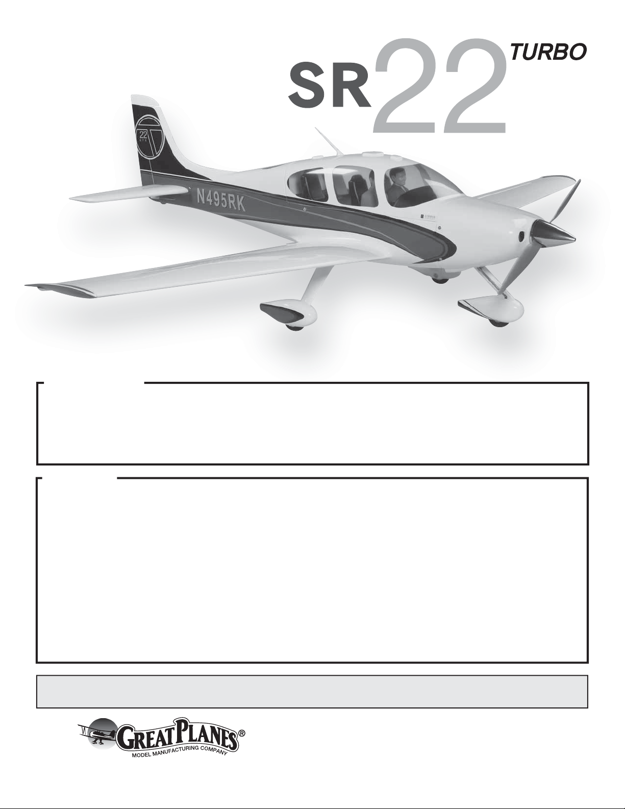
2. Remove the tape and separate the aileron and fl ap servo
❏
covers from the wing. Use a covering iron with a covering
sock on medium heat to tighten the covering if necessary.
Apply pressure over sheeted areas to thoroughly bond the
covering to the wood. If any adhesive from the tape is left
behind, a paper towel dampened with lighter fl uid can be
used to remove the adhesive.
3. Give the ailerons and fl aps a pull to check that the
❏
hinges are securely glued. This should also be done between
each fl ight.
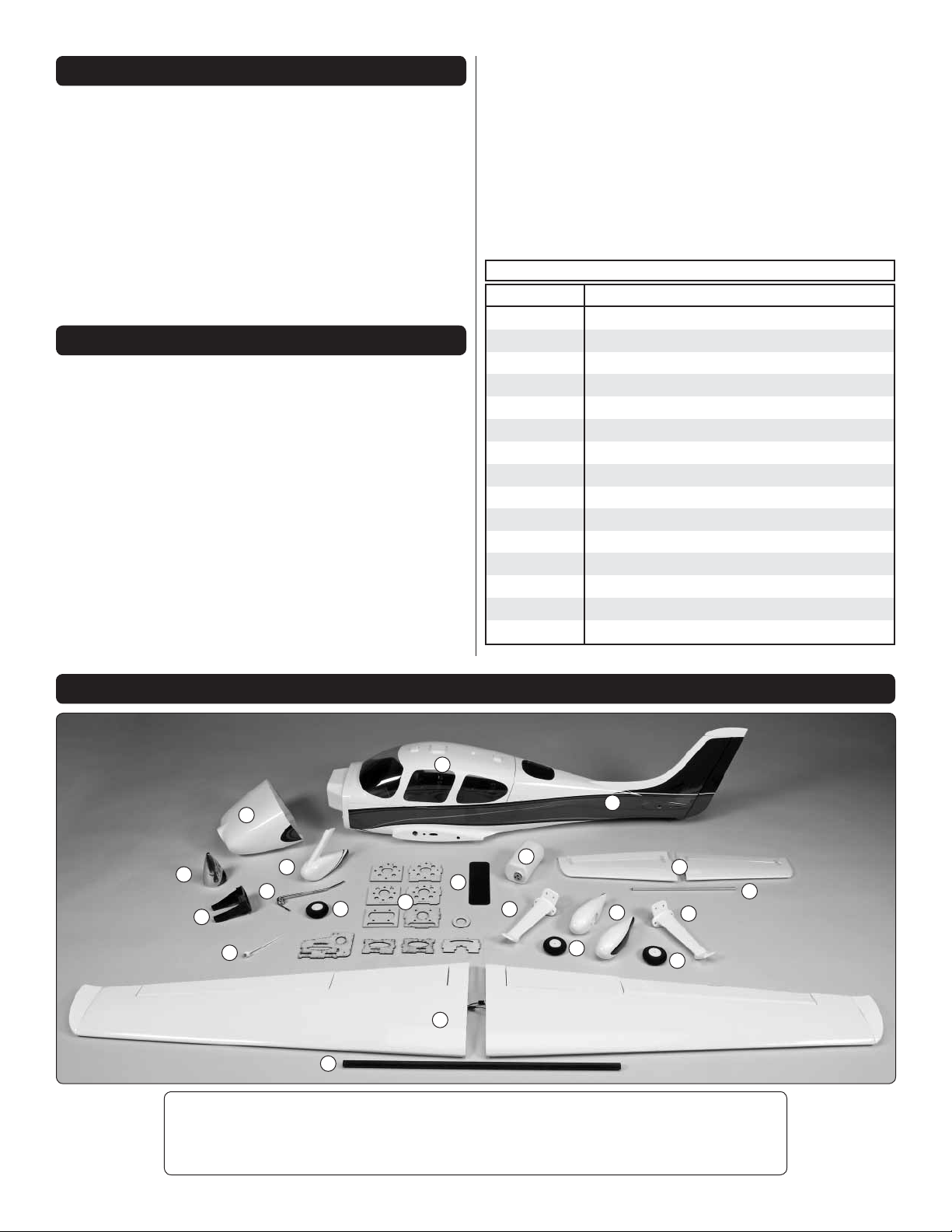
3.
❏ ❏
the two 3/16" x 3/8" x 1/2" [4.8 x 9.5 x 12.7mm] hardwood
blocks to the bottom of the aileron servo cover.
Use a T-pin to prick small holes in the bottom of the blocks
and the servo cover to help the glue hold more securely.
Be careful to not poke the T-pin through the servo cover.
Noting the grain direction, use 6-minute epoxy to glue
ASSEMBLE THE WINGS
Start the assembly with the left wing so that the pictures
match your assembly.
Install the Aileron Servo
1. Connect a 16" [406mm] servo extension to one of
❏ ❏
the aileron servos. Cut a piece of black heat shrink tubing
in half. Slide the heat shrink tubing over the connector. Shrink
the tubing by heating it.
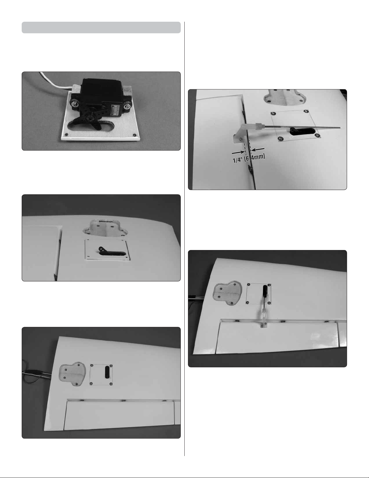
2.
❏ ❏
the aileron servo on the bottom of the aileron servo cover so
that the servo arm output shaft is centered in the opening.
Install the eyelets and grommets in the servos. Position
4. Once the epoxy has cured, place a 1/32" [.8mm]
❏ ❏
spacer such as a piece of cardstock from a header card
or a piece of paper folded several times, under the servo,
between each mounting block. After the servo is installed
the spacer will be removed providing adequate spacing for
vibration isolation.
5. Drill 1/16" [1.6mm] holes through the blocks for the
❏ ❏
servo mounting screws. Mount the servo to the blocks with
the screws that came with the servo. Remove the servo
mounting screws and apply a couple of drops of thin CA in
each hole to harden the threads. Allow the CA to fully harden.
Then, reinstall the servo and remove the spacer.
6
Page 7
6. Use the string in the wing to pull the aileron servo
❏ ❏
wire through the wing.
7. Plug the aileron servo into your receiver, switch on
❏ ❏
the transmitter and receiver and center the aileron servo
trim. Position a servo arm on the aileron servo so that it is
perpendicular to the aileron servo.
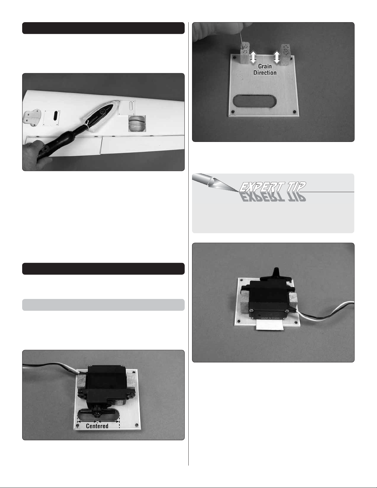
8. Place the aileron servo cover with the servo in the
❏ ❏
wing. Be certain that the cover is positioned correctly as
shown. Use the servo cover as a guide to drill 1/16" [1.6mm]
holes through the plate in the wing. Secure the cover using
four #2 x 3/8" [9.5mm] sheet metal screws and four #2 fl at
washers. Use thin CA to harden the screw threads.
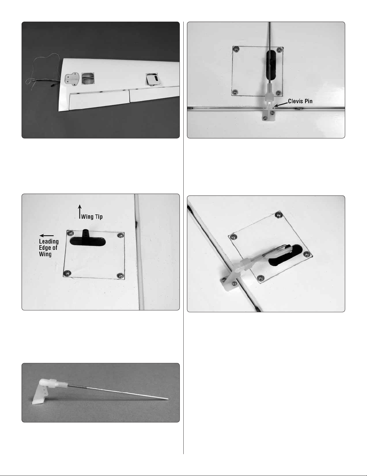
10. Position the control horn so that it is inline with
❏ ❏
the aileron servo horn and the clevis pin is aligned with the
aileron hinge line. On the aileron, mark the two mounting
holes. Remove the control horn and drill a 1/16" [1.6mm]
pilot hole at each mark. Do not drill completely through the
aileron. Attach the control horn using two #2 x 3/8" [9.5mm]
sheet metal screws. Use thin CA to harden the holes.
11 Center the aileron servo and aileron. Mark the pushrod
❏ ❏
where it meets the outer hole of the servo arm. Remove the
pushrod from the aileron control horn and make a 90° bend
at the mark. Reinstall the pushrod on the aileron control horn.
Insert the L-bend in the aileron servo arm and secure it with a
nylon Faslink. Cut the pushrod 1/32" [.8mm] past the Faslink
and slide the clevis retainer over the clevis.
9. Thread a nylon clevis 20 turns onto the end of a
❏ ❏
2-56 x 4" [102mm] metal pushrod. Slide a silicone clevis
retainer over the clevis. Install the clevis in the outer most
hole of a nylon control horn.
7
Page 8
Install the Flap Servo
1. Connect a 9" [229mm] servo extension to one of the
❏ ❏
fl ap servos. Cut a piece of black heat shrink tubing in half.
Slide the heat shrink tubing over the connector. Shrink the
tubing by heating it.
2.
❏ ❏
the same procedure used to install the aileron servo.
❏ ❏
through the wing.
Install the fl ap servo on the fl ap servo cover following
3. Use the string in the wing to pull the fl ap servo wire
Use the servo cover as a guide to drill 1/16" [1.6mm] holes
through the plate in the wing. Secure the cover using four #2
x 3/8" [9.5mm] sheet metal screws and four #2 fl at washers.
Use thin CA to harden the screw threads.
6. Thread a nylon clevis 20 turns onto the end of a 2-56
❏ ❏
x 4" [102mm] metal pushrod. Slide a silicone clevis retainer
over the clevis. Install the clevis in the outer most hole of a
nylon control horn.
7. Position the control horn so that it is inline with
❏ ❏
the fl ap servo horn and the base of the control horn is 1/4"
[6.4mm] from the trailing edge of the wing. On the fl ap, mark
the two mounting holes. Remove the control horn and drill a
1/16" [1.6mm] pilot hole at each mark. Do not drill completely
through the fl ap. Attach the control horn using two #2 x 3/8"
[9.5mm] sheet metal screws. Use thin CA to harden the holes.
4. Plug the fl ap servo into your receiver. Position the
❏ ❏
fl ap dial or slider on the transmitter to the fl ap up position.
Position a servo arm on the fl ap servo so that it is rotated
towards the trailing edge of the wing. Move the fl ap control
to check that the servo arm does not hit the fl ap servo cover.
5. Place the fl ap servo cover with the servo in the wing.
❏ ❏
Be certain that the cover is positioned correctly as shown.
8. With the fl ap in the up position and the servo arm
❏ ❏
rotated back, mark the pushrod where it meets the hole
11/16" [17.5mm] from the center of the servo arm. Remove
the pushrod from the fl ap control horn and make a 90° bend
at the mark. Reinstall the pushrod on the fl ap control horn.
Insert the L-bend in the fl ap servo arm and secure it with a
nylon Faslink. Cut the pushrod 1/32" [.8mm] past the Faslink
and slide the clevis retainer over the clevis.
9. Return to step one of Install the Aileron Servo and
❏
install the aileron and fl ap servos in the right wing panel
(page 6).
8
Page 9
Install the Main Landing Gear
1. Locate the fi berglass left main landing gear by
❏ ❏
fi tting the main gear in the recess in the left wing. If a glow
engine will be installed, fuelproof the main landing gear
recess with thin CA or epoxy thinned with denatured alcohol.
4. Apply a drop of thread locker to the threads of a
❏ ❏
6-32 x 1/4" [6mm] socket head cap screw. Slide a 4mm
wheel collar onto the axle. Thread the 6-32 x 1/4" [6mm]
socket head cap screw into the wheel collar and tighten it on
the fl at at the end of the axle.
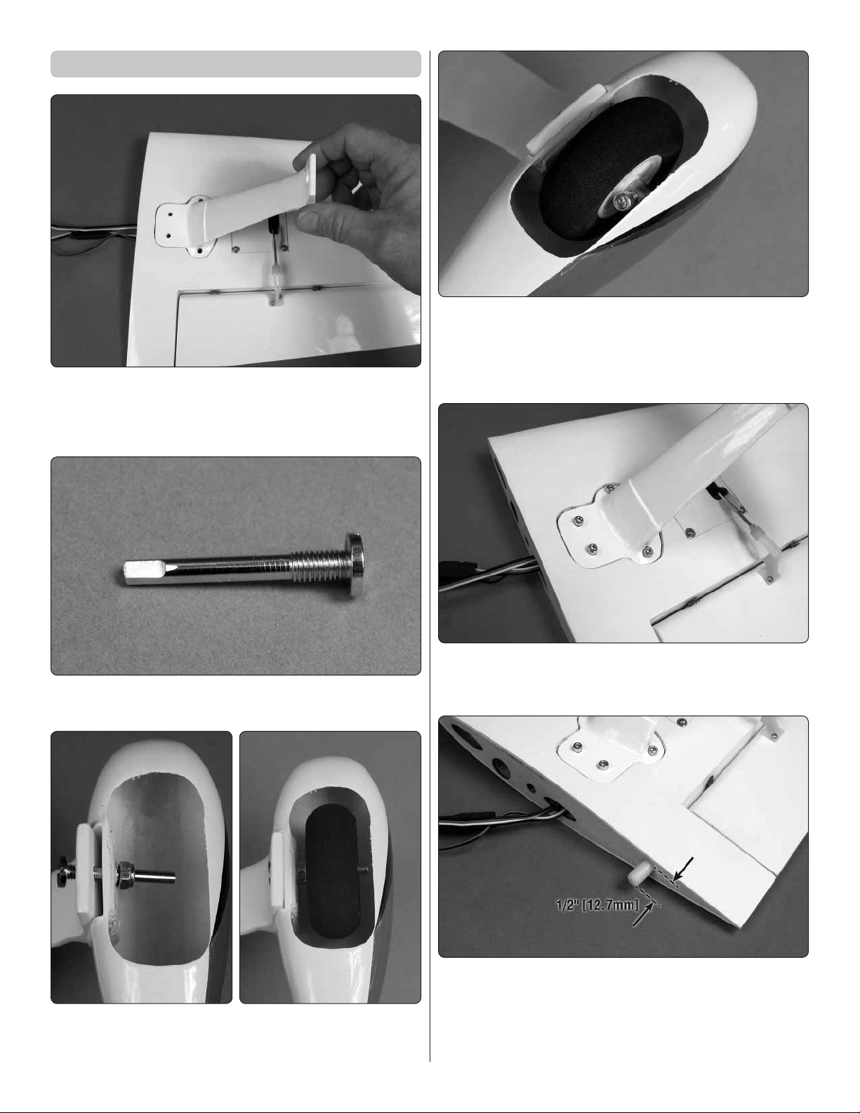
2. File a 1/4" [6.3mm] long fl at spot on the end of the
❏ ❏
main landing gear axle.
3. Insert the axle through the main landing gear and
❏ ❏
the left wheel pant. Slide an axle nut onto the axle followed
by a 2" [51mm] foam wheel. Tighten the axle nut on the axle.
5. Apply a drop of thread locker to the threads of four
❏ ❏
6-32 x 1/2" [12.7mm] socket head cap screws. Secure the
main landing gear to the wing with the cap head screws.
6. Use epoxy to glue the nylon wing dowel in the root
❏ ❏
of the wing. Position the dowel so that 1/2" [12.7mm] of the
dowel is protruding from the wing.
7. Go back to step 1 of Install The Main Landing Gear
❏ ❏
and install the right main landing gear.
9
Page 10
ASSEMBLE THE FUSELAGE
Install the Stabilizer
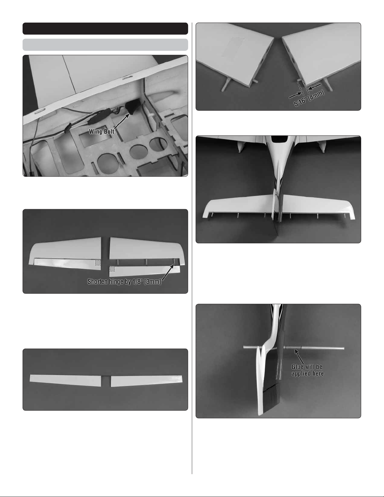
1. Insert the carbon fi ber wing joiner tube in the fuselage.
❏
Slide the two wing halves onto the tube and secure the wing
halves to the fuselage with two 1/4-20 nylon wing bolts.
4.
Use epoxy to glue the two 1/8" x 5/8" [3 x 16mm] nylon
❏
stabilizer dowels 5/16" [8mm] into the root of the stabilizers.
2. Test fi t the elevator halves on the stabilizer halves
❏
using the six pivot point hinges. The two hinges that are
inserted in the elevator halves at the tip need to be shortened
1/8" [3mm]. Note on one side of the elevator halves there is
a hardwood plate under the covering for the elevator control
horn screws. This side should be face downward.
3. Place a piece of tape on the left elevator half and the
❏
left stabilizer half to identify that they go together. Remove
the elevator halves from the stabilizer halves. Insert the
elevator joiner wire in the elevator halves and place the
assembly on a fl at surface. Check that both trailing edges of
the elevators are fl at on the surface. If they are not, remove
and bend the elevator joiner wire slightly and check again.
Also mark the left side of the elevator joiner wire.
5. Slide the 5/16" x 9-3/4" [8 x 248mm] aluminum
❏
stabilizer joiner tube through the fuselage. Temporarily
install the two stabilizer halves on the aluminum stabilizer
joiner tube.
6. View the plane from the aft end. Check that the stabilizer
❏
and wing are parallel to each other.
7. Remove the stabilizer halves and tube. Use sandpaper
❏
to roughen the aluminum tube. Clean the tube with a
paper towel dampened with denatured alcohol. Reinstall
the aluminum tube, centering it in the fuselage. Mark the
aluminum tube on both sides of the fuselage where they
meet. Pull the tube out one side so that glue can be applied
between the lines (do not apply the glue yet).
10
Page 11

8. Gather together a couple of sheets of paper towel,
❏
denatured alcohol, mixing cup, mixing stick, epoxy brush, 8"
[203mm] or longer wire (not included) and 30-minute epoxy.
9. Mix together 1/2 oz. [15cc] of 30-minute epoxy. Apply
❏
epoxy between the lines on the aluminum tube. Center the
tube. Use a paper towel dampened with denatured alcohol to
wipe away any epoxy before it runs down the fuselage. Apply
epoxy to the rest of the aluminum tube. Using the long wire
apply epoxy inside the tube in both stabilizer halves and to
the root of both stabilizer halves. Slide the stabilizer halves
onto the aluminum tubes so that they are tight against the
fuselage. Use masking tape to hold the stabilizer halves in
position. Wipe off any excess epoxy.
the way into the elevator halves. Use a toothpick to remove
any excess epoxy the squeezes out. Then, fi t the elevator
halves the rest of the way on.
Move the elevator up and down a few times to help align
the hinges and make certain that the elevator halves defl ect
up and down enough. Allow the epoxy to cure, checking it a
couple of times while it cures.
Install the Elevator and Rudder Servos
1. Insert a 2-56 x 36" [914mm] metal pushrod in the
❏
hole on the aft left side of the fuselage.
10. After the epoxy has cured, insert the elevator joiner
❏
wire, making sure that the marked left side of the wire is on
the left side of the fuselage.
11. Remove the six pivot point hinges. Apply a small drop
❏
of oil to the pivot point on the hinges. This will prevent the
epoxy from adhering to the pivot point. Make sure oil does
not get on the gluing surface of the hinge. If it does, clean the
oil off with a paper towel dampened with denatured alcohol.
12. Mix approximately 1/4 oz. [7.4cc] of 30-minute epoxy.
❏
Use a toothpick to thoroughly apply the epoxy in the holes
for the hinges in the stabilizer and elevator halves. Also apply
epoxy in the holes for the elevator joiner wire in the elevator
halves. Wipe off any excess epoxy around the outside of the
holes with a paper towel dampened with denatured alcohol.
Use the toothpick to apply epoxy to the ends of the hinges that
go into the stabilizer. Insert the hinges into the stabilizer and
wipe away any excess epoxy that squeezes out of the hole.
Apply epoxy to the other end of the hinges. Join the elevator
halves to the stabilizer, pushing the hinges only about 3/4 of
2. Mount the elevator servo in the radio tray. Remember
❏
to harden the screw holes with thin CA.
3.
Thread a nylon clevis 20 turns onto the end of the elevator
❏
pushrod. Slide a silicone clevis retainer over the clevis. Install
the clevis in the outer most hole of a nylon control horn.
11
Page 12

4. Position the control horn on the elevator so that the
❏
four holes on the control horn are inline with the elevator
hinge line. Mark the two control horn mounting holes on the
elevator. Remove the control horn and drill a 1/16" [1.6mm]
pilot hole at each mark. Do not drill completely through the
elevator. Attach the control horn using two #2 x 3/8" [9.5mm]
sheet metal screws. Use thin CA to harden the holes.
Install the Nose Gear
1. File a fl at spot at the end of the nose gear axle. The
❏
fl at spot should be on the same side as one of the small
threaded holes.
5. Center the elevator servo and elevator. Mark the pushrod
❏
where it meets the hole 7/16" [11mm] from the center of the
servo arm. Remove the pushrod from the elevator control horn
and make a 90° bend at the mark. Reinstall the pushrod on the
elevator control horn. Insert the L-bend in the elevator servo arm
and secure it with a nylon Faslink. Cut the pushrod 1/32" [.8mm]
past the Faslink and slide the clevis retainer over the clevis
6. Install the rudder servo following the same procedure
❏
used to install the elevator servo. Note: Position the rudder
servo so that the rudder pushrod is aligned with the hole
11/16" [17.6mm] from the center of the servo arm.
.
12
2. Slide a black plastic wheel spacer onto the axle, followed
❏
by a foam wheel and a 4mm wheel collar. Apply a drop of
thread locker to a 6-32 x 1/4" [6mm] socket head cap screw
and secure the wheel collar on the axle with the cap screw.
Page 13

3. Use sandpaper to roughen the nose gear wire (where
❏
shown) and the slot in the wheel pant. Then clean both
areas with a paper towel dampened with denatured alcohol.
4. Insert the nose gear wire in the wheel pant. Apply a
❏
drop of thread locker to a 6-32 x 1/4" [6mm] socket head cap
screw. Thread the cap screw into a 4mm wheel collar. Slide
the wheel collar on the nose gear wire and tighten the cap
screw on the lower fl at spot.
6. Install the nose gear axle assembly on the nose gear
❏
wire. Tighten the set screw on the fl at spot at the end of the
nose gear wire.
7. Use epoxy or RTV Silicone glue to glue the nose gear
❏
wire in the slot of the wheel pant. Make sure the foam wheel
is aligned in the wheel pant and the wheel collar is next to
the top of the wheel pant.
5. Apply a drop of thread locker to a 3x4mm set screw.
❏
Install the set screw in the nose gear axle, opposite the cap
screw in the wheel collar.
8. Center the nosegear decal on the front of the nosegear
❏
and wrap around the sides.
13
Page 14

9. Install the nylon nose gear steering block to the front
❏
of the fuselage with four 6-32 x 5/8" [16mm] socket head
cap screws, #6 fl at washers and #6 lock washers. Apply a
drop of thread locker on the threads of the cap screws before
installing.
10. Cut a 2-56 x 36" [914mm] metal pushrod in half.
❏
Save the piece with the threads on it for the throttle pushrod.
Make a bend 3/8" [9.5mm] from the end of the non-threaded
18" [457mm] metal pushrod.
12. Insert the bent end of the pushrod in the outer hole of
❏
the steering arm. Slide the pushrod in the hole in the fi rewall.
Insert the nose gear wire in the nose gear block and through
the steering arm. Tighten the cap screw in the steering arm
against the fl at spot on the nose gear wire. Adjust the steering
arm and the lower wheel collar so that the end of the nose gear
wire does not hit the bottom of the fi rewall. Bend the pushrod
as necessary to allow the steering arm to rotate freely.
11. Insert a 4mm wheel collar into the nylon steering
❏
arm. Align the hole in the side of the steering arm with the
threaded hole in the side of the wheel collar. Apply a drop of
thread locker to a 6-32 x 1/4" [6mm] socket head cap screw
and thread it into the wheel collar. Use a 5/64" [2mm] drill bit
to enlarge the outer hole in the steering arm.
13. Install the Screw-lock Pushrod Connector in the
❏
hole 7/16" [11mm] from the center of the rudder servo arm.
Secure the connector with the nylon retainer.
14
Page 15

14. Make a bend in the steering pushrod so that it is
❏
aligned with the screw-lock pushrod connector. Center
the servo arm and nose wheel. Cut the steering pushrod
1/4" [6mm] past the pushrod connector. Insert the steering
pushrod in the pushrod connector. Apply a drop of thread
locker to the threads of a 4-40 x 1/4" socket head cap screw.
Secure the steering pushrod in the pushrod connector with
the cap screw.
Install the Motor
Note: If you are installing a glow engine, proceed to page 17,
Install The Engine.
1. The motor box can be assembled for the RimFire .55
❏
motor or the O.S. .50 motor. Use epoxy to glue the two
plywood motor box back plates together and the motor
box front plates. Note that the front plates are embossed
RimFire or O.S. (see picture above).
15. Make a strap by overlapping a piece of hook material
❏
with a piece of loop material by 1" [25.4mm].
16. Place the receiver on a piece of R/C foam. Secure the
❏
receiver and foam to the radio tray with the hook and loop
material. Trim off the excess material. Plug in the rudder and
elevator servos.
2. Install four 6-32 blind nuts in the back of the motor
❏
box front plate. Use epoxy or CA to glue the blind nuts in the
front plate. Be careful to not get glue on the threads of the
blind nuts.
15
Page 16

4. Attach the motor box to the fi rewall with four 6-32 x
❏
5/8" [16mm] socket head cap screws, #6 fl at washers and
#6 lock washers. Be sure to apply a drop of thread locker to
the threads of the cap screws.
5. Assemble the motor following the instructions included
❏
with the motor. Attach the motor to the motor box with four
6-32 x 1/2" [13mm] socket head cap screws, #6 fl at
washers and #6 lock washers. Be sure to apply a drop of
thread locker to the threads of the cap screws. Note: First
insert all four cap screws in the motor X-mount before
threading them into the motor box.
3. Use epoxy to securely glue the motor box together.
❏
6. Use three #4 x 3/8" [9.5mm] sheet metal screws to
❏
install the ECS to the bottom plate of the motor box. Harden
the screw holes with thin CA.
16
Page 17

7. Make a hole in the front of the fuselage to route the
❏
battery plug and ESC control wire into the fuselage. Plug the
ESC into the receiver. Connect the three motor wires to the
ESC. See page 21, step 5 for hole location.
8. Cut three 1" [25.4mm] long pieces of hook material (the
❏
rough material) and glue it to the battery tray using CA glue.
Install the Engine
9. Glue a strip of loop material to the side of the motor battery.
❏
10. Make a battery strap and secure the battery to the
❏
battery tray. The receiver battery and switch will be installed
once everything else is installed and the C.G. is checked.
This will determine their location.
Proceed to step 2 of Install The Cowl (page 20).
1. Side mount the nylon engine mount on the fi rewall with
❏
four 6-32 x 1" [25.4mm] socket head cap screws, #6 fl at
washers and #6 lock washers. Position the engine between
the engine mount halves before tightening the cap screws.
Be sure to apply a drop of thread locker to the threads of the
cap screws. Note: The top of the engine mount has two lines
on it. Position the engine mount so that the center line on the
fi rewall is between the two lines on the engine mount.
2. Position the engine so that the front of the drive washer
❏
is 4-3/8" [111mm] from the front of the fi rewall. Use the
engine mounting holes as a guide to drill 7/64 [2.7mm] pilot
holes in the nlyon engine mount. Use a 6-32 tap to thread
the holes in the nylon engine mount.
17
Page 18

3. Install the engine on the engine mount with four 6-32
❏
x 1" [25.4mm] socket head cap screws, #6 fl at washers and
#6 lock washers.
7. Make the throttle pushrod by threading a nylon clevis 20
❏
turns onto the leftover 2-56 x 17-1/2" [444mm] metal pushrod
(previously cut from the 36" [914mm] metal pushrod). Slide a
silicone clevis retainer over the clevis.
8. Insert the throttle pushrod into the outer pushrod tube
❏
in the fi rewall. Make any bends required to allow the clevis to
snap into the outer hole of the throttle arm.
4. Drill a 3/16" [4.7mm] hole through the fi rewall, in line
❏
with the throttle arm.
5. Use sandpaper to roughen the 10" [254mm] outer
❏
pushrod tube. Wipe the tube off with a paper towel
dampened with denatured alcohol.
6. Glue the throttle outer pushrod tube in the fi rewall and
❏
the plywood fuselage former. Trim the hole in the fi rewall to
allow the tube to be glued straight.
9. Install the throttle servo in the servo tray. Be sure to
❏
harden the screw holes with thin CA. Plug the throttle servo
into the receiver.
10. Install a screw-lock pushrod connector in the hole
❏
7/16" [11mm] from the center of the servo arm. Secure the
18
Page 19

connector with a nylon retainer. Switch on the radio system.
Center the throttle stick on the transmitter and install a servo
arm on the throttle servo perpendicular to the centerline of
the servo.
Install the Fuel Tank
1. Insert the one long and two short aluminum tubes
❏
through the large fuel tank stopper plate, rubber fuel tank
stopper and the small fuel tank stopper plate. Thread the
fuel tank stopper screw into the small fuel stopper plate.
Do not tighten the screw.
11. Make the bends necessary to align the pushrod with
❏
the pushrod connector. Insert the pushrod in the connector.
Apply a drop of thread locker to the threads of a 4-40 x 1/4"
[6mm] socket head cap screw. Install the cap screw in the
pushrod connector. With the radio system switch on and the
throttle stick centered, center the barrel of the carb, then
tighten the cap screw in the pushrod connector.
Setting the throttle up this way will only require a small
amount of end point adjustment, if any. We also recommend
that a throttle-cut be set up on a switch on your transmitter.
2. Make a 90° bend in the long aluminum tube (pressure
❏
tube). Do not kink the tube. Install the two silicone fuel tubes
on the short aluminum tubes. Trim the fuel tubing so that
the metal clunks are able to move in the fuel tank. Install the
metal clunks on the fuel tubing.
3. Insert the fuel tank stopper in the fuel tank. Make sure
❏
that the pressure tube is toward the top of the fuel tank.
Tighten the fuel tank stopper screw.
19
Page 20

4. Place the plywood fuel tank spacer over the neck of
❏
the fuel tank.
5. Install three pieces of fuel tubing (not included) on the
❏
aluminum tubes exiting the fuel tank. Mark the pressure
tubing. Glue a piece of RC foam to the fuel tank tray. This will
keep the fuel tank from sliding around. Route the fuel tubing
and the neck of the fuel tank through the hole in the fi rewall.
7. Install the muffl er and connect the fuel line from the
❏
pressure tube to the muffl er. The end of the muffl er screw
may need to be fi led down if the screw is hitting the fuselage.
Install the Cowl
6. Make a hook and loop strap (as you did for the receiver)
❏
and secure the fuel tank to the fuel tank tray. Connect one
of the fuel lines from the clunk to the carburetor. The second
line from the clunk will be routed out the bottom of the cowl
and used to fi ll and drain the fuel tank.
1. Tape a piece of card stock to the bottom of the fuselage.
❏
Trim the card stock around the muffl er.
20
Page 21

2. Remove the muffl er. Install the cabin/hatch on the
❏
fuselage. Slide the cowl over the engine or motor. Trim the
bottom of the cowl to fi t around the nose gear.
Electric Only: Also open the intake on the left side of the
cowl for better motor cooling. Then, proceed to step 5.
3. Use the card stock method to locate the needle valve.
❏
5. On the left front side of the fuselage, cut a hole to route
❏
the landing light wires into the fuselage.
Electric Only: Route the landing light wires through the
same hole the ESC wires pass through.
4. Remove the needle valve, position the cowl on the front
❏
of the fuselage and use the card stock templates to mark the
cowl for the muffl er and needle valve and trim the openings.
An opening will also need to be cut for the glow starter using
the card stock method. Reinstall the muffl er and adjust the
openings so that the cowl fi ts well and the graphics on the
fuselage align with the ones on the cowl.
6. Tape pieces of card stock to the outside of the fuselage
❏
to mark the location of the cowl mounting blocks.
21
Page 22

7. Insert the landing light wires through the hole in the
❏
front of the fuselage. Position the cowl on the fuselage.
Install the spinner backplate on the prop shaft. Position the
cowl so that it is centered on the spinner backplate. Tape the
cowl in position.
Electric Only: With the RimFire .55 or O.S. .50 motor, the
center of the spinner backplate will need to be enlarged to
5/16" [8mm].
8. Drill a 1/16" [1.6mm] pilot hole through the cowl and
❏
cowl blocks. Remove the cowl and enlarge the holes in the
cowl with a 3/32" [2.4mm] drill bit.
10. Install a suitable propeller for the power system
❏
being used. Secure it with the prop washer (included with
the engine) and the appropriate spinner adapter. Carefully
balance the propeller and any spare propellers before
installation. An unbalanced propeller can be the single most
signifi cant cause of vibration that can damage the model.
Not only will engine mounting bolts loosen, possibly with
disastrous effect, but vibration may also damage the receiver
and receiver batteries. Vibration can also cause the fuel to
foam, which will, in turn, cause the engine to run hot and quit.
We use a Top Flite Precision Magnetic Prop Balancer
(TOPQ5700) in the workshop and keep a Great Planes
Fingertip Prop Balancer (GPMQ5000) in our fl ight box.
9. As you install the cowl, route the fi ll line out the bottom
❏
of the cowl and install the fuel line plug (glow powered only).
Attach the cowl to the fuselage with four #2 x 3/8" 9.5mm]
sheet metal screws and #2 fl at washers. Be sure to harden
the screw holes with thin CA.
11. Install the spinner nose cone and secure it with 4 x
❏
45mm socket head cap screw.
22
Page 23

Install the Receiver Battery
1. Secure the cabin to the fuselage with two 4-40 x 3/8"
❏
[9.5mm] machine screws and #4 fl at washers.
4. If the plane is nose heavy, wrap the receiver battery in
❏
R/C foam and secure it between the servos with a hook and
loop strap. If the plane is tail heavy, the receiver battery can
be mounted under the front of the battery tray.
5. Once the location of the receiver battery has been
❏
determined, the receiver switch and charge jack can be
installed in the side of the fuselage.
2. Place a mark on the top of both wing halves 2-1/4"
❏
[56mm] from the leading edge of the wing.
3. Turn the plane upside-down. Try balancing the plane on
❏
your fi nger tips at the marks. If the plane is electric powered,
try moving the motor battery forward or aft to get it to balance.
Electric Options:
to connect the motor battery, the receiver switch and charge
jack could be installed inside the fuselage. Another option is a
voltage regulator (CSEM0005) could be installed, eliminating
the receiver battery. The voltage regulator connects between
the motor battery and receiver using the motor battery to
power the receiver.
1
Since the cabin will need to be removed
FINISH THE MODEL
1. Plug two Y-harnesses into the aileron and the fl ap
❏
channels on the receiver. Plug the light controller into an
open channel on the receiver. Connect one of the three
connectors from the light controller to the wire from the light
in the cowl. Use a piece of shrink tubing to secure it.
2. Connect the wing tip lights into the light controller.
❏
Switch on the transmitter and receiver. The landing light and
wing tip lights can be switched on and off from the transmitter.
23
Page 24

3. Now is a good time to organize the wires in the fuselage.
❏
Connect the aileron and fl ap servos to the Y-harnesses.
Straps to hold the wires in position can be made from #64
rubber bands (not included) cut into strips. The strips can be
glued over the wires. Remember, the wires from the wings
cannot be strapped down if the wings are to be removable.
4. The pilot busts (not included, WBRQ1140) that we
❏
installed had to be raised about 1/2" [12.7mm]. A piece of
balsa wood or foam (not included) can be used. Insert the
pilots from the bottom of the cabin and glue them in position.
5. We recommend that a screw be installed through the
❏
bottom of the cabin to help secure the pilots.
6. Glue the cabin bottom cover in place.
❏
7. Clean the recess in the top of the cabin and the post on
❏
the antenna with a paper towel dampened with denatured
alcohol. Glue the antenna post in the recess with epoxy or
silicone RTV.
Apply the Decals
1. The decals are die-cut from the factory.
2. Be certain the model is clean and free from oily fi ngerprints
and dust. Prepare a dishpan or small bucket with a mixture
of liquid dish soap and warm water—about 1/2 teaspoon of
soap per gallon of water. Submerse one of the decals in the
solution and peel off the paper backing. Note: Even though
the decals have a “sticky-back” and are not the water transfer
type, submersing them in soap & water allows accurate
positioning and reduces air bubbles underneath.
3.
Position decal on the model where desired. Holding the
decal down, use a paper towel to wipe most of the water away.
4. Use a piece of soft balsa or something similar to squeegee
remaining water from under the decal. Apply the rest of the
decals the same way.
24
Page 25

Please use the following pictures and box top as a guide for
FULL
THROTTLE
RUDDER
MOVES
RIGHT
ELEVATOR
MOVES DOWN
RIGHT AILERON
MOVES UP
LEFT AILERON
MOVES DOWN
4-CHANNEL RADIO SET UP (STANDARD MODE 2)
the decal placement.
GET THE MODEL READY TO FLY
Balance the Model Laterally
1. With the wing level, have an assistant help you lift the
❏
model by the propeller shaft and the bottom of the fuse under
the TE of the fi n. Do this several times.
2. If one wing always drops when you lift the model, it
❏
means that side is heavy. Balance the airplane by adding
weight to the other wing tip. An airplane that has been
laterally balanced will track better in loops and other
maneuvers.
Check the Control Directions
1. Switch on the transmitter and receiver and center the
❏
trims. If necessary, remove the servo arms from the servos
and reposition them so they are centered. Reinstall the
screws that hold on the servo arms.
CAUTION ELECTRIC ONLY: If the receiver is powered
by the motor battery, REMOVE the propeller before
checking the control directions. Once the motor battery
is connected, the motor is live and could cause serious
injury if it should start.
2. With the transmitter and receiver still on, check all the
❏
control surfaces to see if they are centered. If necessary,
adjust the clevises on the pushrods to center the control
surfaces.
3.
Make certain that the control surfaces and the carburetor
❏
(glow powered) respond in the correct direction as shown
in the diagram. If any of the controls respond in the wrong
direction, use the servo reversing in the transmitter to reverse
the servos connected to those controls. Be certain the control
surfaces have remained centered. Adjust if necessary.
25
Page 26

Set the Control Throws
The pushrod farther out
means More Throw
The pushrod closer in
means Less Throw
The pushrod farther out
means Less Throw
The pushrod closer in
means More Throw
At the Servos
At the Control Surfaces
These are the recommended
control surface throws:
ELEVATOR
HIGH RATE LOW RATE
7/16"
[11mm]
17°
Up
7/16"
[11mm]
17°
Down
5/16"
[8mm]
12°
Up
5/16"
[8mm]
12°
Down
3/4"
[19mm]
21°
Up
3/4"
[19mm]
21°
Down
5/8"
[16mm]
17°
Up
5/8"
[16mm]
17°
Down
1-1/2"
[38mm]
35°
Down
1"
[25mm]
30°
Right
1"
[25mm]
30°
Left
5/8"
[16mm]
18°
Right
5/8"
[16mm]
18°
Left
RUDDERAILERONSFLAPS
To ensure a successful fi rst fl ight, set up your Cirrus SR22
ARF according to the control throws specifi ed in this
manual. The throws have been determined through actual
fl ight testing and accurate record-keeping, allowing the
model to perform in the manner in which it was intended. If,
after you have become accustomed to the way the Cirrus
SR22 ARF fl ies, you would like to change the throws to
suit your taste, that is fi ne. However, too much control
throw could make the model too responsive and diffi cult to
control, so remember, “more is not always better.”
3. If necessary, adjust the location of the pushrod on the
❏
servo arm or on the elevator horn, or program the ATVs in
your transmitter to increase or decrease the throw according
to the measurements in the control throws chart.
1. Hold a ruler vertically on your workbench against the
❏
widest part (front to back) of the trailing edge of the elevator.
Note the measurement on the ruler.
2. Measure the high rate elevator throw fi rst. Move the
❏
elevator up with your transmitter and move the ruler forward
so it will remain contacting the trailing edge. The distance
the elevator moves up from center is the “up” elevator throw.
Measure the down elevator throw the same way.
4. Measure and set the low rate elevator throws and the
❏
high and low rate throws for the rest of the control surfaces
the same way. If your radio does not have dual rates, we
recommend setting the throws at the high rate settings.
NOTE: The throws are measured at the widest part of the
elevators, rudder and ailerons.
26
Page 27

Balance the Model (C.G.)
More than any other factor, the C.G. (center of gravity/
balance point) can have the greatest effect on how a model
fl ies and could determine whether or not your fi rst fl ight will
be successful. If you value your model and wish to enjoy it
for many fl ights, DO NOT OVERLOOK THIS IMPORTANT
PROCEDURE. A model that is not properly balanced may
be unstable and possibly unfl yable.
At this stage the model should be in ready-to-fl y condition
with all of the components in place including the complete
radio system, engine or motor, muffl er, propeller, spinner
and pilot. The fuel tank should be empty or on the electric
powered version, the motor battery should be installed.
2. With the wing attached to the fuselage, all parts of the
❏
model installed (ready to fl y) and an empty fuel tank, place
the model upside-down on a Great Planes CG Machine, or
lift it upside-down at the balance point you marked.
3. If the tail drops, the model is “tail heavy.” If the nose
❏
drops, the model is “nose heavy.” Use Great Planes “stick-on”
lead (GPMQ4485) to balance the plane. To fi nd out how
much weight is required, place incrementally increasing
amounts of weight on the bottom of the fuselage over the
location where it would be mounted inside until the model
balances. A good place to add stick-on nose weight is to the
fi rewall. Do not attach weight to the cowl—this will cause
stress on the cowl and could cause the cowl to crack at the
screw holes. Once you have determined if additional weight
needs to be installed, it can be permanently attached.
1. If using a Great Planes C.G. Machine, set the rulers to
❏
2-1/4" [57mm]. If not using a C.G. Machine, use a fi ne-point
felt tip pen to mark lines on the top of the wing on both sides of
the fuselage 2-1/4" [57mm] back from the leading edge. Apply
narrow (1/16" [2mm]) strips of tape over the lines so you will
be able to feel them when lifting the model with your fi ngers.
This is where your model should balance for the fi rst
fl ights. Later, you may experiment by shifting the C.G. 1/8"
[3mm] forward or 1/8" [3mm] back to change the fl ying
characteristics. Moving the C.G. forward will improve the
smoothness and stability, but the model will then be less
aerobatic (which may be fi ne for less-experienced pilots).
Moving the C.G. aft makes the model more maneuverable
and aerobatic for experienced pilots. In any case, start at
the recommended balance point and do not at any time
balance the model outside the specifi ed range.
Do not rely upon the adhesive on the back of the lead weight
to permanently hold it in place. Over time, fuel, vibration and
exhaust residue may soften the adhesive and cause the
weight to fall off. Instead, permanently attach the weight with
glue or screws.
Note: On the electric powered version move the motor
battery forward or aft before adding additional weight to
the nose or tail.
4. IMPORTANT: If you found it necessary to add any
❏
weight, recheck the C.G. after the weight has been installed.
PREFLIGHT
Identify Your Model
No matter if you fl y at an AMA sanctioned R/C club site or if
you fl y somewhere on your own, you should always have your
name, address, telephone number and AMA number on or
inside your model. It is required at all AMA R/C club fl ying sites
and AMA sanctioned fl ying events. Fill out the identifi cation tag
on page 30 and place it on or inside your model.
Charge the Batteries
Follow the battery charging instructions that came with your
radio control system to charge the batteries. You should
always charge your transmitter and receiver batteries
the night before you go fl ying, and at other times as
recommended by the radio manufacturer.
27
Page 28

CAUTION: Unless the instructions that came with your
radio system state differently, the initial charge on new
transmitter and receiver batteries should be done for 15
hours using the slow-charger that came with the radio
system. This will “condition” the batteries so that the next
charge may be done using the fast-charger of your choice.
If the initial charge is done with a fast-charger the batteries
may not reach their full capacity and you may be fl ying with
batteries that are only partially charged.
Ground Check and Range Check
Run the engine for a few minutes to make sure it idles reliably,
transitions smoothly and maintains full power indefi nitely.
Afterward, shut the engine off and inspect the model closely,
making sure all fasteners, pushrods and connections have
remained tight and the hinges are secure. Always ground
check the operational range of your radio before the fi rst fl ight
of the day following the manufacturer’s instructions that came
with your radio. This should be done once with the engine off
and once with the engine running at various speeds. If the
control surfaces do not respond correctly, do not fl y! Find and
correct the problem fi rst. Look for loose servo connections or
broken wires, corroded wires on old servo connectors, poor
solder joints in your battery pack or a defective cell, or a
damaged receiver crystal from a previous crash.
The engine and motor get hot! Do not touch during or right
after operation. Make sure fuel lines are in good condition so
fuel will not leak onto a hot engine, causing a fi re.
To stop a glow engine, cut off the fuel supply by closing
off the fuel line or following the engine manufacturer’s
recommendations. Do not use hands, fi ngers or any other
body part to try to stop the engine. Do not throw anything
into the propeller of a running engine.
When working on your plane, remove the propeller if the
motor battery will be connected.
Always remove the motor battery from the plane when charging.
Follow the charging instructions included with your charger
for charging LiPo batteries. LiPo batteries can cause serious
damage if misused. DO NOT leave charging batteries
unattended!
AMA SAFETY CODE (EXCERPTS)
Read and abide by the following excerpts from the Academy
of Model Aeronautics Safety Code. For the complete Safety
Code refer to Model Aviation magazine, the AMA web site or
the Code that came with your AMA license.
General
ENGINE SAFETY PRECAUTIONS
Failure to follow these safety precautions may result
in severe injury to yourself and others.
Keep all engine fuel in a safe place, away from high heat,
sparks or fl ames, as fuel is very fl ammable. Do not smoke
near the engine or fuel; and remember that engine exhaust
gives off a great deal of deadly carbon monoxide. Therefore
do not run the engine in a closed room or garage.
Get help from an experienced pilot when learning to operate
glow engines and electric motors.
Use safety glasses when starting or running engines.
Do not run the engine in an area of loose gravel or sand; the
propeller may throw such material in your face or eyes.
Keep your face and body as well as all spectators away from
the plane of rotation of the propeller as you start and run the
engine.
Keep these items away from the prop: loose clothing, shirt
sleeves, ties, scarfs, long hair or loose objects such as
pencils or screwdrivers that may fall out of shirt or jacket
pockets into the prop.
Use a “chicken stick” or electric starter to start the engine.
Do not use your fi ngers to fl ip the propeller. Make certain the
glow plug clip or connector is secure so that it will not pop off
or otherwise get into the running propeller.
Make all engine adjustments from behind the rotating propeller.
1)
I will not fl y my model aircraft in sanctioned events, air shows,
or model fl ying demonstrations until it has been proven to be
airworthy by having been previously, successfully fl ight tested.
2) I will not fl y my model aircraft higher than approximately
400 feet within 3 miles of an airport without notifying the
airport operator. I will give right-of-way and avoid fl ying in the
proximity of full-scale aircraft. Where necessary, an observer
shall be utilized to supervise fl ying to avoid having models fl y
in the proximity of full-scale aircraft.
3) Where established, I will abide by the safety rules for the
fl ying site I use, and I will not willfully and deliberately fl y my
models in a careless, reckless and/or dangerous manner.
5) I will not fl y my model unless it is identifi ed with my name
and address or AMA number, on or in the model. Note: This
does not apply to models while being fl own indoors.
7) I will not operate models with pyrotechnics (any device
that explodes, burns, or propels a projectile of any kind).
Radio Control
1) I will have completed a successful radio equipment ground
check before the fi rst fl ight of a new or repaired model.
2) I will not fl y my model aircraft in the presence of spectators
until I become a qualifi ed fl ier, unless assisted by an
experienced helper.
3) At all fl ying sites a straight or curved line(s) must be
established in front of which all fl ying takes place with the
other side for spectators. Only personnel involved with fl ying
the aircraft are allowed at or in the front of the fl ight line.
Intentional fl ying behind the fl ight line is prohibited.
28
Page 29

4)
I will operate my model using only radio control frequencies
currently allowed by the Federal Communications Commission.
5) I will not knowingly operate my model within three
miles of any pre-existing fl ying site except in accordance
with the frequency sharing agreement listed [in the
complete AMA Safety Code].
9) Under no circumstances may a pilot or other person
touch a powered model in fl ight; nor should any part of the
model other than the landing gear, intentionally touch
the ground, except while landing.
CHECK LIST
During the last few moments of preparation your mind may
be elsewhere anticipating the excitement of the fi rst fl ight.
Because of this, you may be more likely to overlook certain
checks and procedures that should be performed before the
model is fl own. To help avoid this, a check list is provided
to make sure these important areas are not overlooked.
Many are covered in the instruction manual, so where
appropriate, refer to the manual for complete instructions.
Be sure to check the items off as they are completed.
Fuelproof all areas exposed to fuel or exhaust residue.
❏ 1.
Check the C.G. according to the measurements
❏ 2.
provided in the manual.
Be certain the battery and receiver are securely
❏ 3.
mounted in the fuse. Simply stuffi ng them into place with
foam rubber is not suffi cient.
If you still fl y on 72MHz, Extend your receiver antenna
❏ 4.
and make sure it has a strain relief inside the fuselage to
keep tension off the solder joint inside the receiver.
Balance your model laterally as explained in the
❏ 5.
instructions.
Use threadlocking compound to secure critical fasteners
❏ 6.
such as the set screws that hold the wheel axles to the struts,
screws that hold the carburetor arm (if applicable), engine
bolts, etc
❏ 7.
❏ 8.
to make sure all hinges are securely glued in place.
❏ 9.
appropriate (servo mounting screws, aileron hatches, etc.).
❏
and the throws are set up according to the manual. Checking
the direction should be performed before every fl ight. With
computer radios it is easy to mistakenly change the model.
❏
clevises and that all servo arms are secured to the servos
with the screws included with your radio.
❏
Y-connectors or servo extensions, and the connection between
your battery pack and the on/off switch with vinyl tape, heat
shrink tubing or special clips suitable for that purpose.
❏
have used do not interfere with other systems (servo arms,
pushrods, etc.).
.
Add a drop of oil to the axles so the wheels will turn freely.
Give the control surfaces a quick tug before every fl ight
Reinforce holes for wood screws with thin CA where
10. C
onfi rm that all controls operate in the correct direction
11. Make sure there are silicone retainers on all the
12. Secure connections between servo wires and
13. Make sure any servo extension cords you may
14. Make sure the fuel lines are connected and are not
❏
kinked.
15. Balance your propeller (and spare propellers).
❏
16. Check that the spinner bolt is tight.
❏
17. Place your name, address, AMA number and telephone
❏
number on or inside your model. This is an AMA rule (see
page 31 of this manual).
18. Cycle your receiver battery pack (if necessary) and
❏
make sure it is fully charged.
19. If you wish to photograph your model, do so before
❏
your fi rst fl ight.
20. Range check your radio when you get to the fl ying
❏
fi eld. Have an assistant hold the plane while running the
engine at different throttle settings.
FLYING
The Cirrus SR22 ARF is a great-fl ying model that fl ies
smoothly and predictably. The Cirrus SR22 ARF does not,
however, possess the self-recovery characteristics of a
primary R/C trainer and should be fl own only by experienced
R/C pilots.
Fuel Mixture Adjustments
A fully cowled engine may run at a higher temperature
than an un-cowled engine. For this reason, the fuel mixture
should be richened so the engine runs at about 200 rpm
below peak speed. By running the engine slightly rich, you
will help prevent dead-stick landings caused by overheating.
Also, the left opening is closed in the cowl to force cooling
air over the head of the engine. If the engine overheats, the
opening around the muffl er may need to be enlarged slightly
to allow more cooling air to exit.
CAUTION (THIS APPLIES TO ALL R/C AIRPLANES): If,
while fl ying, you notice an alarming or unusual sound such as
a low-pitched “buzz,” this may indicate control surface fl utter.
Flutter occurs when a control surface (such as an aileron or
elevator) or a fl ying surface (such as a wing or stab) rapidly
vibrates up and down (thus causing the noise). In extreme
cases, if not detected immediately, fl utter can actually cause
the control surface to detach or the fl ying surface to fail, thus
causing loss of control followed by an impending crash. The
best thing to do when fl utter is detected is to slow the model
immediately by reducing power, then land as soon as safely
possible. Identify which surface fl uttered (so the problem
may be resolved) by checking all the servo grommets for
deterioration or signs of vibration. Make certain all pushrod
linkages are secure and free of play. If it fl uttered once, under
similar circumstances it will probably fl utter again unless the
problem is fi xed. Some things which can cause fl utter are;
Excessive hinge gap; Not mounting control horns solidly; Poor
fi t of clevis pin in horn; Side-play of wire pushrods caused
by large bends; Excessive free play in servo gears; Insecure
servo mounting; and one of the most prevalent causes of
fl utter; Flying an over-powered model at excessive speeds.
29
Page 30

Takeoff
Before you get ready to takeoff, see how the model handles
on the ground by doing a few practice runs at low speeds
on the runway. If necessary, adjust the nose wheel so the
model will roll straight down the runway. If you need to calm
your nerves before the maiden fl ight, shut the engine down
and bring the model back into the pits. Top off the fuel, then
check all fasteners and control linkages for peace of mind.
Remember to takeoff into the wind. When you’re ready, point
the model straight down the runway and then gradually
advance the throttle. Gain as much speed as your runway
and fl ying site will practically allow before gently applying up
elevator, lifting the model into the air. At this moment it is likely
that you will need to apply some right rudder to counteract
engine torque. Be smooth on the elevator stick, allowing the
model to establish a gentle climb to a safe altitude before
turning into the traffi c pattern.
Flight
For reassurance and to keep an eye on other traffi c, it is a
good idea to have an assistant on the fl ight line with you. Tell
him to remind you to throttle back once the plane gets to a
comfortable altitude. While full throttle is usually desirable for
takeoff, most models fl y more smoothly at reduced speeds.
Take it easy with the Cirrus SR22 ARF for the fi rst few fl ights,
gradually getting acquainted with it as you gain confi dence.
Adjust the trims to maintain straight and level fl ight. After
fl ying around for a while, and while still at a safe altitude
with plenty of fuel, practice slow fl ight and execute practice
landing approaches by reducing the throttle and lowering the
fl aps to see how the model handles at slower speeds. Add
power to see how she climbs as well. Continue to fl y around,
executing various maneuvers and making mental notes (or
having your assistant write them down) of what trim or C.G.
changes may be required to fi ne tune the model so it fl ies
the way you like. Mind your fuel level or battery power, but
use this fi rst fl ight to become familiar with your model before
landing.
to overshoot, smoothly advance the throttle (always ready
on the right rudder to counteract torque) and retract the
fl aps when enough airspeed is gained. Climb out to make
another attempt. When the model is a foot or so off the deck,
smoothly increase up elevator until it gently touches down.
Note: If ever the occasion arises when a dead-stick landing
must be performed, do not extend the fl aps until certain the
model will be able to reach the landing zone (on dead-stick
landings it is common to land with no fl aps at all). Without
power, fl aps can unexpectedly reduce the model’s range,
thus causing you to come up short of the fi eld.
One fi nal note about fl ying your model. Have a goal or fl ight
plan in mind for every fl ight. This can be learning a new
maneuver(s), improving a maneuver(s) you already know,
or learning how the model behaves in certain conditions
(such as on high or low rates). This is not necessarily to
improve your skills (though it is never a bad idea!), but more
importantly so you do not surprise yourself by impulsively
attempting a maneuver and suddenly fi nding that you’ve run
out of time, altitude or airspeed. Every maneuver should be
deliberate, not impulsive. For example, if you’re going to do a
loop, check your altitude, mind the wind direction (anticipating
rudder corrections that will be required to maintain heading),
remember to throttle back at the top, and make certain you
are on the desired rates (high/low rates). A fl ight plan greatly
reduces the chances of crashing your model just because
of poor planning and impulsive moves. Remember to think.
Have a ball!
But always stay in control and fl y in a safe manner.
GOOD LUCK AND GREAT FLYING!
Landing
The Cirrus SR22 ARF may be landed with or without fl aps.
Flaps increase lift and drag, so the plane may be landed
slower, thus reducing rollout after touchdown (not as much
of a factor on grass runways). The Cirrus SR22 is a clean
airplane and does not slow down quickly. To initiate a landing
approach, lower the throttle while on the downwind leg. If
using fl aps, allow the model to slow before extending them.
Continue to lose altitude, but maintain airspeed by keeping
the nose down as you turn onto the crosswind leg. Make
your fi nal turn toward the runway (into the wind) keeping the
nose down to maintain airspeed and control. If using fl aps,
keep a few additional “clicks” of power so the model doesn’t
slow too much. Level the attitude when the model reaches
the runway threshold, modulating the throttle as necessary
to maintain your glide path and airspeed. If you are going
30
Page 31

31
Phone Number
AMA Number
City, State, Zip
Address
This model belongs to:
Name
Page 32

 Loading...