

Great Planes GPMA1357 User Manual
WARRANTY
Great Planes
®
Model Manufacturing Co. guarantees this kit to be free from defects in both material and workmanship at the date of
purchase.This warranty does not cover any component parts damaged by use or modification. In no case shall Great Planes’ liability
exceed the original cost of the purchased kit. Further, Great Planes reserves the right to change or modify this warranty without notice.
In that Great Planes has no control over the final assembly or material used for final assembly, no liability shall be assumed nor
accepted for any damage resulting from the use by the user of the final user-assemb led product.By the act of using the user-assembled
product, the user accepts all resulting liability.
If the buyer is not prepared to accept the liability associated with the use of this product, the buyer is advised to return this
kit immediately in new and unused condition to the place of purchase.
To make a warranty claim send the defective part or item to Hobby Services at the address below:
Hobby Services
3002 N. Apollo Dr., Suite 1
Champaign, IL 61822 USA
Include a letter stating your name, return shipping address, as much contact information as possible (daytime telephone number, fax
number, e-mail address), a detailed description of the problem and a photocopy of the purchase receipt. Upon receipt of the package
the problem will be evaluated as quickly as possible.
READ THROUGH THIS MANUAL BEFORE STARTING
CONSTRUCTION. IT CONTAINS IMPORTANT WARNINGS
AND INSTRUCTIONS CONCERNING THE ASSEMBLY
AND USE OF THIS MODEL.
GPMZ1357 for GPMA1357 V1.0Entire Contents © Copyright 2006
Champaign, Illinois
(217) 398-8970, Ext 5
airsupport@greatplanes.com
INSTRUCTION MANUAL
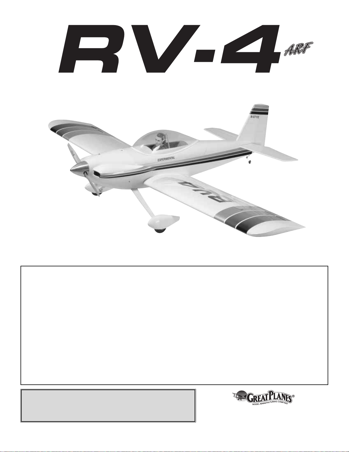
Wingspan: 70 in [1780mm]
Wing Area: 1036 sq in [67dm2]
Weight: 9.5 – 10.5 lb [4310 – 4760g]
Wing Loading: 21 – 23 oz/sq ft [64 – 70g/dm2]
Length: 63 in [1600mm]
Radio: 5-channel with six 54 oz-in servos and one 30 oz-in servo
Glow Engine: .61 – .75 cu in [10 – 12cc] two-stroke, .91 cu in [15cc] four-stroke
Electric Motor: 50-65-450 RimFire™motor
2
INTRODUCTION..................................................................2
AMA.....................................................................................2
IMAA....................................................................................2
SAFETY PRECAUTIONS....................................................3
DECISIONS YOU MUST MAKE ..........................................3
Radio Equipment...........................................................3
Engine Recommendations ............................................3
Electric Motor & Motor Mount Recommendations ...........4
ADDITIONAL ITEMS REQUIRED.......................................4
Adhesives & Building Supplies ......................................4
Optional Supplies & Tools..............................................4
IMPORTANT BUILDING NOTES.........................................4
ORDERING REPLACEMENT PARTS .................................5
KIT INSPECTION ................................................................6
KIT CONTENTS...................................................................6
METRIC / INCH RULER......................................................6
PREPARATIONS .................................................................7
ASSEMBLY INSTRUCTIONS..............................................7
ASSEMBLE THE WING.......................................................7
Install the Ailerons & Flaps ..................................................7
Install the Aileron, Flap Servos & Pushrods ........................8
ASSEMBLE THE FUSELAGE...........................................10
Install the Stab, Elevators & Rudder..................................10
Install the Landing Gear & Wheel Pants............................11
Electric Motor / Glow Engine Installation ...........................13
Electric Motor, ESC & Battery Installation .........................13
Install the Glow Engine, Fuel Tank & Throttle Servo..........14
Install the Radio, Servos & Pushrods ................................17
Assemble the Canopy........................................................20
Install the Cowl ...................................................................21
Apply the Decals................................................................23
GET THE MODEL READY TO FLY ...................................23
Check the Control Directions.......................................23
Set the Control Throws................................................23
Balance the Model (C.G.) ............................................24
Balance the Model Laterally........................................24
PREFLIGHT.......................................................................25
Identify Your Model ......................................................25
Charge the Batteries ...................................................25
Balance the Propellers ................................................25
Ground Check .............................................................25
Range Check ...............................................................25
ENGINE SAFETY PRECAUTIONS...................................25
MOTOR & BATTERY SAFETY PRECAUTIONS...............26
AMA SAFETY CODE (excerpts)......................................26
IMAA SAFETY CODE (excerpts).....................................27
CHECK LIST......................................................................28
FLYING...............................................................................29
Fuel Mixture Adjustments............................................29
Takeoff .........................................................................29
Flight............................................................................29
Landing........................................................................29
For the latest technical updates or manual corrections to the
RV-4 ARF visit the Great Planes web site at
www.greatplanes.com. Open the “Airplanes” link, then
select the RV-4 ARF. If there is new technical information or
changes to this model a “tech notice” box will appear in the
upper left corner of the page.
We urge you to join the AMA (Academy of Model
Aeronautics) and a local R/C club.The AMA is the governing
body of model aviation and membership is required to fly at
AMA clubs.Though joining the AMA provides many benefits,
one of the primary reasons to join is liability protection.
Coverage is not limited to flying at contests or on the club
field. It even applies to flying at public demonstrations and
air shows. Failure to comply with the Safety Code (excerpts
printed in the back of the manual) may endanger insurance
coverage.Additionally, training programs and instructors are
available at AMA club sites to help you get started the right
way. There are over 2,500 AMA chartered clubs across the
country. Contact the AMA at the address or toll-free phone
number below.
IMPORTANT!!! Two of the most important things you can do
to preserve the radio controlled aircraft hobby are to avoid
flying near full-scale aircraft and avoid flying near or over
groups of people.
The Great Planes RV-4 ARF is an excellent sport-scale model
and is eligible to fly in IMAA events. The IMAA (International
Miniature Aircraft Association) is an organization that
promotes non-competitive flying of giant-scale models. If you
plan to attend an IMAA event, obtain a copy of the IMAA
Safety Code by contacting the IMAA at the address or
telephone number below, or by logging on to their web site at:
IMAA
205 S. Hilldale Road
Salina, KS 67401
(913) 823-5569
www.fly-imaa.org/imaa/sanction.html
Though the Great Planes RV-4 is an ARF and may not have
the same level of detail as an “all-out”scratch-built competition
model, it is a scale model nonetheless and is therefore eligible
to compete in the Fun Scale class in AMA competition (we
receive many f avorable reports of Great Planes ARFs in scale
competition!).In Fun Scale, the “builder of the model”rule does
not apply. To receive the five points for scale documentation,
Scale Competition
IMAA
Academy of Model Aeronautics
5151 East Memorial Drive
Muncie, IN 47302
Tele: (800) 435-9262
Fax (765) 741-0057
Or via the Internet at:
http://www.modelaircraft.org
AMA
INTRODUCTION
TABLE OF CONTENTS
the only proof required that a full size aircraft of this type in this
paint/markings scheme did exist is a single sheet such as a kit
box cover from a plastic model, a photo, or a profile painting,
etc. If the photo is in black and white other written
documentation of color must be provided.Contact the AMA for
a rule book with full details.
If you would like photos of full-size RV-4’s for scale
documentation, or if you would like to study the photos to
add more scale details, photo packs are available from:
Bob’s Aircraft Documentation
3114 Y uk on Ave .
Costa Mesa, CA 92626
Telephone: (714) 979-8058
Fax:(714) 979-7279
E-mail: www.bobsairdoc.com
1.Your RV-4 ARF should not be considered a toy, but rather
a sophisticated, working model that functions very much like
a full-size airplane. Because of its performance capabilities,
the RV-4 ARF, if not assembled and operated correctly,
could possibly cause injury to yourself or spectators and
damage to property.
2. You must assemble the model according to the
instructions. Do not alter or modify the model, as doing so
may result in an unsafe or unflyable model. In a few cases
the instructions may differ slightly from the photos.In those
instances the written instructions should be considered
as correct.
3.You must take time to build straight, true and strong.
4. You must use an R/C radio system that is in first-class
condition, and a correctly sized engine and components
(fuel tank, wheels, etc.) throughout the building process.
5.You must correctly install all R/C and other components so
that the model operates correctly on the ground and in the air .
6.You must check the operation of the model before every
flight to insure that all equipment is operating and that the
model has remained structurally sound. Be sure to check
clevises or other connectors often and replace them if they
show any signs of wear or fatigue.
7. If you are not an experienced pilot or have not flown this
type of model before, we recommend that you get the
assistance of an experienced pilot in your R/C club for your
first flights.If you're not a member of a club, y our local hobb y
shop has information about clubs in your area whose
membership includes experienced pilots.
8.While this kit has been flight tested to exceed normal use,
if the plane will be used for extremely high-stress flying,
such as racing, or if an engine larger than one in the
recommended range is used, the modeler is responsible for
taking steps to reinforce the high-stress points and/or
substituting hardware more suitable for the increased stress .
9. WARNING:The cowl and wheel pants included in this kit
are made of fiberglass, the fibers of which may cause eye,
skin and respiratory tract irritation. Never blow into a part
(wheel pant, cowl) to remove fiberglass dust, as the dust will
blow back into your eyes. Always wear safety goggles, a
particle mask and rubber gloves when grinding, drilling and
sanding fiberglass parts. Vacuum the parts and the work
area thoroughly after working with fiberglass parts.
Remember:Take your time and follow the instructions to
end up with a well-built model that is straight and true.
This is a partial list of items required to finish the RV-4 ARF
that may require planning or decision making before starting
to build. Order numbers are provided in parentheses.
❏ 5-Channel radio (minimum)
❏ (6) 54 oz-in Servos and one 30 oz-in servo.
❏ 12" [300mm] Servo extension (HCAM2711 for Futaba
®
)
❏ (2) Y-harnesses (HCAM2751 for Futaba)
❏ 4.8V, 500mAh Batter y or greater
The recommended engine size range for the RV-4 ARF is
.61 to .75 two-stroke or .91 four-stroke. If an engine in the
upper end of the size range is used, remember that this is a
scale model that is intended to fly at scale-like speeds, so
throttle management should be practiced.
Engine Recommendations
Radio Equipment
DECISIONS YOU MUST MAKE
We, as the kit manuf acturer, provide you with a top quality ,
thoroughly tested kit and instructions, but ultimately the
quality and flyability of your finished model depends on
how you build it; therefore, we cannot in any way
guarantee the performance of your completed model, and
no representations are expressed or implied as to the
performance or safety of your completed model.
PRO TECT YOUR MODEL,Y OURSELF
& OTHERS...FOLLOW THESE
IMPORTANT SAFETY PRECAUTIONS
3
We have flown the RV-4 ARF extensively on a variety of
motors to find the best performance for this airplane. The
following items proved to power the plane very well, giving
similar performance to the .91 glow engine.
Motor
• C50-65-450 RimFire™brushless out-runner
motor (GPMG4770)
• SS 80 Silver Series 80A ESC (GPMM1860)
• (4) 3 x 8mm Machine screws
• (4) 3mm Washers
Motor Mount
• Brushless Motor Mount (large, GPMG1260)
Prop
• APC 16x8E or 16x6 standard prop for a glow engine
Battery
We tested this plane with LiP o and NiMH batteries.The LiPo
batteries provided slightly longer flight times and weighed
less than the NiMH batteries.
• 6S1P 3200mAh LiPo battery (2) ElectriFly™3200mAh
11.1V batteries, GPMP0623)
• One Series Adapter, (2) Deans males (GPMM3143)
or
• 12 volt (10-cell) 3600 NiMH battery with flat Deans
Connectors (GPMP0363)
We recommend the Great Planes ElectriFly PolyCharge 4
™
LiPo charger (GPMM3015) for LiPo batteries and the Triton
™
Peak Charger (GPMM3150) for NiMH batteries.
❏ 1/2 oz. [15g] Thin Pro
™
CA (GPMR6001)
❏ 1 oz. [30g] Medium Pro CA+ (GPMR6008)
❏ Pro 6-minute epoxy (GPMR6045)
❏ Drill bits: 1/32" [.8mm], 1/16" [1.6mm], 5/64" [2mm],
3/32" [2.4mm], 9/64" [3.6mm], 3/16" [4.8mm].
❏ 8-32 Tap and drill set (GPMR8103)
❏ R/C-56 canopy glue (JOZR5007)
❏ CA applicator tips (HCAR3780)
❏ Mixing sticks (50, GPMR8055)
❏ Mixing cups (GPMR8056)
❏ Masking tape (TOPR8018)
❏ Threadlocker
™
thread-locking compound (GPMR6060)
❏ R/C foam rubber (1/4" [6mm] – HCAQ1000, or
1/2" [13mm] – HCAQ1050)
❏ 3' [900mm] Standard silicone fuel tubing (GPMQ4131,
for glow engine installation only!)
❏ Fuel Filler Valve (for glow fuel GPMQ4160)
❏ Stick-on segmented lead weights (GPMQ4485)
❏ Silver Solder w/flux (GPMR8070)
❏ #1 Hobby knife (HCAR0105)
❏ #11 Blades (5-pack, HCAR0211)
❏ Small T-pins (100, HCAR5100)
❏ 21st Century
®
sealing iron (COVR2700)
❏ 21st Century iron cover (COVR2702)
❏ 21st Century trim seal iron (COVR2750)
❏ 2 oz. [57g] Spray CA activator (GPMR6035)
❏ CA debonder (GPMR6039)
❏ Curved-tip canopy scissors (for trimming plastic
parts HCAR0667)
❏ Robart Super Stand II (ROBP1402)
❏ CG Machine
™
(GPMR2400)
❏ Rotary tool such as Dremel
®
❏ Rotary tool reinforced cut-off wheel (GPMR8020)
❏ Servo horn drill (HCAR0698)
❏ Hobby Heat
™
micro torch (HCAR0750)
❏ Dead Center
™
engine mount hole
locator (GPMR8130)
❏ AccuThrow
™
deflection gauge (GPMR2405)
❏ Denatured alcohol (for epoxy clean up)
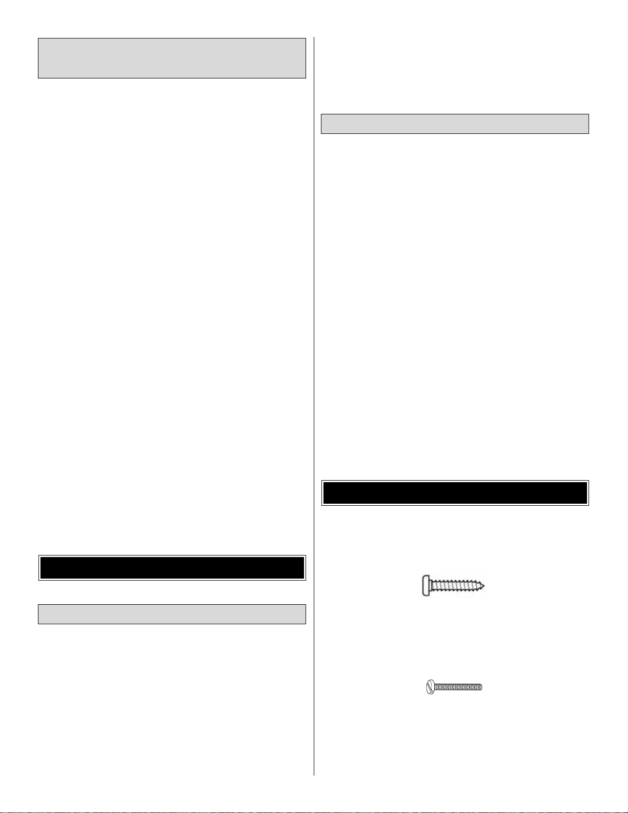
• Sheet Metal Screws (SMS) are designated by a
number and a length. For example #6 x 3/4" [19mm].
This is a number six screw that is 3/4" [19mm] long.
• Machine Screws (MS) are designated by a number,
threads per inch, and a length. For example 4-40 x
3/4" [19mm].
This is a number four screw that is 3/4" [19mm] long
with forty threads per inch.
• Socket Head Cap Screws (SHCS) are designated by a
number, threads per inch, and a length. For example 4-40 x
1-1/2" [38mm].
IMPORTANT BUILDING NOTES
Optional Supplies & Tools
Adhesives & Building Supplies
ADDITIONAL ITEMS REQUIRED
Electric Motor & Motor
Mount Recommendations
4

This is a number four screw that is 1-1/2" [38mm] long
with forty threads per inch.
• When you see the term
test fit
in the instructions, it
means that you should first position the part on the
assembly without using any glue, then slightly modify or
custom fit
the part as necessar y for the best fit.
• Whenever the term
glue
is written you should rely upon
your experience to decide what type of glue to use.When a
specific type of adhesive works best for that step, the
instructions will make a recommendation.
• Whenever just
epoxy
is specified you may use either
30-minute (or 45-minute) epoxy or 6-minute epoxy. When
30-minute epoxy is specified it is highly recommended that
you use only 30-minute (or 45-minute) epoxy, because you
will need the working time and/or the additional strength.
•
Photos
and
sketches
are placed before the step they
refer to. Frequently you can study photos in following steps
to get another view of the same parts.
• The RV-4 ARF is factory-covered with Top Flite
®
MonoKote®film. Should repairs ever be required, MonoKote
can be patched with additional MonoKote purchased
separately. MonoKote is packaged in six-foot rolls, but some
hobby shops also sell it by the foot. If only a small piece of
MonoKote is needed for a minor patch, perhaps a fellow
modeler would give you some. MonoKote is applied with a
model airplane covering iron, but in an emergency a regular
iron could be used. A roll of MonoKote includes full
instructions for application.Following are the colors used on
this model and order numbers for six foot rolls.
White – TOPQ0204
Aluminum – TOPQ0205
Black – TOPQ0208
Metallic Red – TOPQ0405
• The stabilizer and wing incidences and engine thrust
angles have been factory-built into this model. However,
some technically-minded modelers may wish to check these
measurements anyway.To vie w this inf ormation visit the web
site at www.greatplanes.com and click on “Technical Data.”
Due to manufacturing tolerances which will have little or no
effect on the way your model will fly, please expect slight
deviations between your model and the published values.
Replacement parts for the Great Planes RV-4 ARF are
available using the order numbers in the Replacement Parts
List that follows.The fastest, most economical service can be
provided by your hobby dealer or mail-order company.
To locate a hobby dealer, visit the Hobbico web site at
www.hobbico.com. Choose “Where to Buy” at the bottom
of the menu on the left side of the page. Follow the
instructions provided on the page to locate a U.S., Canadian
or International dealer.
Parts may also be ordered directly from Hobby Services by
calling (217) 398-0007, or via facsimile at (217) 398-7721,
but full retail prices and shipping and handling charges will
apply. Illinois and Nevada residents will also be charged
sales tax. If order ing via fax, include a Visa®or MasterCard
®
number and expiration date for payment.
Mail parts orders and payments by personal check to:
Hobby Services
3002 N. Apollo Drive, Suite 1
Champaign, IL 61822
Be certain to specify the order number exactly as listed in
the Replacement Parts List. Payment by credit card or
personal check only; no C.O.D.
If additional assistance is required for any reason contact Product
Support by e-mail at productsupport@greatplanes.com,
or by telephone at (217) 398-8970.
Description How to Purchase
Missing pieces Contact Product Support
Instruction manual Contact Product Support
Full-size plans Not available
Kit parts listed below Hobby Supplier
Replacement Parts List
GPMA3030..............Wing Set
GPMA3031..............Wing Tube
GPMA3032..............Fuse w/Hatch
GPMA3033..............Wheel Pants
GPMA3034..............Cowl
GPMA3035..............Landing Gear Set
GPMA3036..............Spinner w/Hardware
GPMA3037..............Canopy
GPMA3038..............Tail Set
GPMA3039..............Decal Sheet
ORDERING REPLACEMENT PARTS
5
6
Before starting to build, take an inventory of this kit to make sure it is complete, and inspect the parts to make sure they
are of acceptable quality. If any parts are missing or are not of acceptable quality, or if you need assistance with assembly,
contact Product Support. When repor ting defective or missing parts, use the part names exactly as they are written in
the Kit Contents list on this page.
Great Planes Product Support
3002 N. Apollo Drive, Suite 1
Champaign, IL 61822
Telephone: (217) 398-8970, ext. 5
Fax: (217) 398-7721
E-mail: airsupport@greatplanes.com
KIT INSPECTION
KIT CONTENTS
19
3
4
7
8
10
12
11
13
20
15
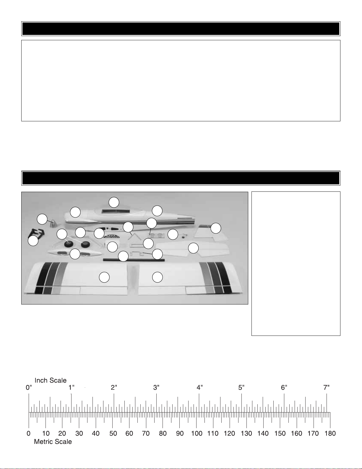
Kit Contents
1. Spinner
2. Engine Mount (L&R)
3. Cowl
4. Canopy
5. Fuselage
6. Wheels (2)
7. Landing Gear
8. Wheels Pants (L&R)
9. Instrument Panel
10. Fuel Tank
11. Aluminum Wing Joiner T ube
12. Turn-Over Post
13. Secondary Ser vo Tray
14. Fuel Tank Former
15. Secondary Receiver/Battery Tray
16. Tail Wheel Assembly
17. Hor izontal Stab & Elevators
18. Vertical Fin & Rudder
19. Left Wing Panel w/Aileron & Flap
20. Right Wing Panel w/Aileron & Flap
1
2
6
5
9
14
16
17
18
To convert inches to millimeters, multiply inches by 25.4
❏ 1. If you have not done so already, remove the major
parts of the kit from the box and inspect for damage. If any
parts are damaged or missing, contact Product Suppor t at
the address or telephone number listed in the
“Kit
Inspection”
section on page 6.
❏ 2. Remove the tape and separate the ailerons and flaps
from the wing and the elevators from the stab. Use a
covering iron with a covering soc k on high heat to tighten the
covering if necessary.Apply pressure over sheeted areas to
thoroughly bond the covering to the wood.
Do the right wing panel first so your work matches the
photos the first time through.
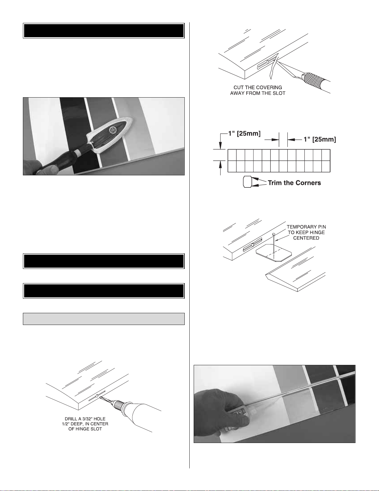
❏❏1. Dr ill a 3/32" hole, 1/2" [13mm] deep in the center of
each hinge slot to allow the CA to “wick”in. Follow-up with a
#11 blade to clean out the slots. Hint: If you have one, use
a high-speed rotary tool to drill the holes.
❏❏2.Use a sharp #11 blade to cut a strip of covering from
the hinge slots in the wing and aileron.
❏❏3. Cut twelve (12) 1" x 1" [25 x 25mm] hinges from the
CA hinge strip. Snip off the cor ners so they go in easier.
❏❏4.Test fit the r ight aileron to the wing with four hinges.
If the hinges don’t remain centered, stick a pin through the
middle of the hinge to hold it in position.
❏❏5. Remove any pins you may have inserted into the
hinges.Adjust the aileron so there is a small gap between the
LE of the aileron and the wing. The gap should be small, just
enough to see light through or to slip a piece of paper through.
❏❏6. Apply six drops of thin CA to the top and bottom of
each hinge. Do not use CA accelerator. After the CA has
fully hardened, test the hinges by pulling on the aileron.
Install the Ailerons & Flaps
ASSEMBLE THE WING
ASSEMBLY INSTRUCTIONS
PREPARATIONS
7
❏❏7. Test fit the right flap to the wing with three hinges.
Using the same procedure used for the ailerons, join the
flaps to the wing.
❏ 8.Repeat steps 1 to 7 for the left wing panel.
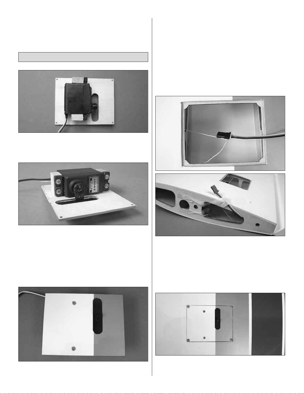
❏❏1.Remove the aileron servo cover from the wing.Position
the aileron servo and center the output shaft over the
opening in the servo cover.Glue a 5/8" x 3/4" x 5/16" [16 x 19 x
8mm] hardwood block to the cover on each side of the servo.
❏❏2. Install the aileron servo into the aileron servo
opening. Drill through the servo mounting holes with a 1/16"
[1.6mm] drill bit. Remove the servo from the servo opening.
Install and then remove a servo mounting screw into each of
the holes you have drilled. Apply a drop of thin CA into the
holes to harden the threads. Once the glue has hardened
install the servo into the servo opening using the hardware
included with your servo. Center the ser vo, and then install
a servo arm as shown.
❏❏3. Make a mark on the servo cover centered over the
servo mounting block. Dr ill through the cover into the servo
mounting block with a 1/16" [1.6mm] drill bit. Install a #2 x
3/8" [9.5mm] wood screw into the hole to secure the servo
block to the cover.
❏❏4. Install a 12" [305mm] servo extension onto the
aileron servo lead. Secure the extension to the lead with
tape, a piece of heat-shrink tubing or some other method to
keep them from coming unplugged.
❏❏5. Taped inside the aileron ser vo opening is a string.
Tie the aileron servo extension to the string in the aileron
servo opening. Pull the servo lead through the wing with the
string that is taped to the root rib. Untie the string from the
leads and tape the lead to the wing root to prevent it from
falling back into the wing.
❏❏6. Drill through the holes in the cor ners of the aileron
servo cover with a 1/16" [1.6mm] drill bit. Install #2 x 3/8"
[9.5mm] SMS and #2 washers in each corner of the cover.
Install the Aileron, Flap Ser vos & Pushrods
8
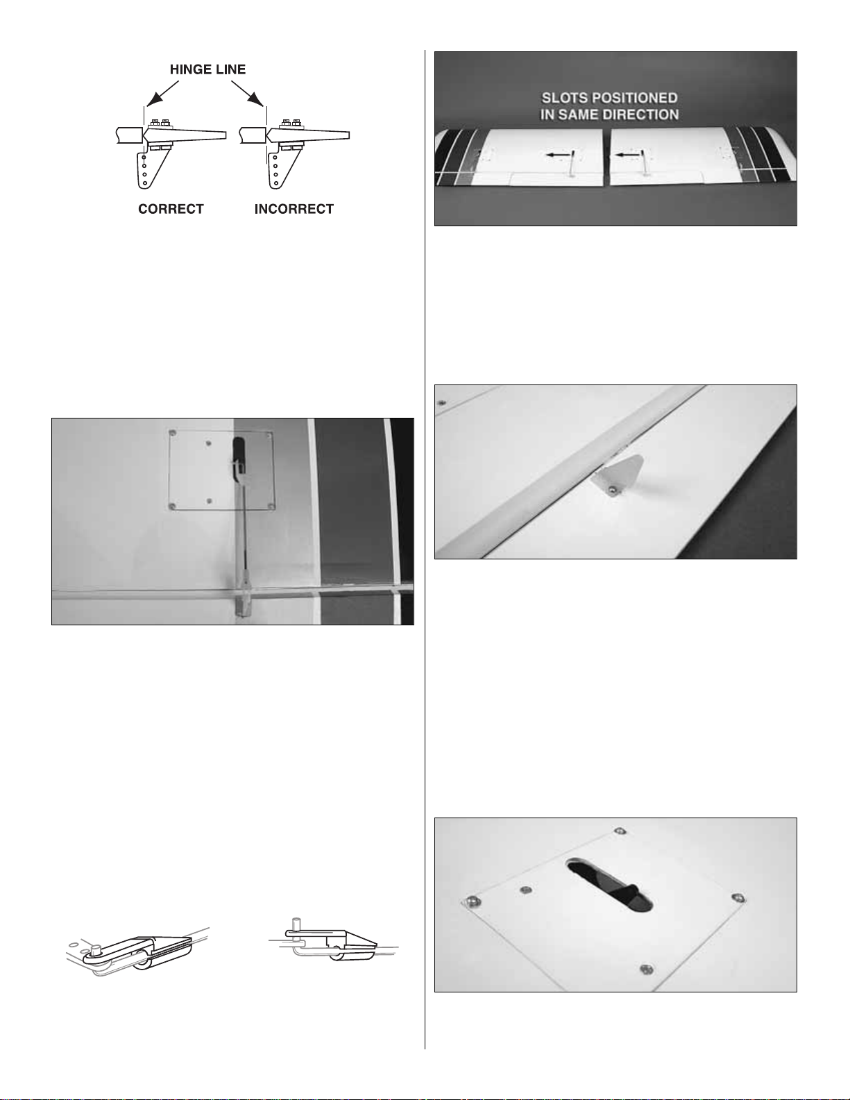
❏❏7. Place a nylon control horn in line with the last hole in
the aileron servo arm. When positioned properly the control
horn will rest on a hardwood plate in the aileron. Mark the
location of the mounting holes onto the aileron. Drill a 1/16"
[1.6mm] hole on the marks, drilling through the plywood plate
but not through the top of the aileron. Insert and remove a #2
x 3/8" [9.5mm] screw into each of the holes. Apply a couple
drops of thin CA into the holes to harden the threads.Once the
glue has hardened attach the control horn to the aileron with
two #2 x 3/8" [9.5mm] screws.
❏❏8. Locate a .074" x 6" [.074" x 152mm] pushrod wire
threaded on one end. Screw a nylon clevis onto the
threaded end of the wire 20 full turns. Install a silicone clevis
keeper onto the clevis.Then, install the clevis in the second
hole from the end of the aileron control horn.
❏❏9. Be sure the aileron ser vo is centered. Enlarge the
outer hole in the servo arm with a Hobbico®Servo Horn Drill
(or a #48 or 5/64" [2mm] drill bit). Center the aileron and
align the wire pushrod with the hole in the end of the servo
arm.Using a marker, mark the location where the wire aligns
with the hole in the servo arm. On that mark make a 90°
bend. From the bend, measure an additional 3/16" [4.8mm].
Then, cut off the excess pushrod wire.
❏❏10. Install the wire into the hole in the servo arm using
a nylon FasLink as shown in the sketch.
❏❏11. Install the flap servo into the flap servo opening,
mounting it using the same procedure for the aileron servo
(no servo extension is required for the flap servo).Install the
servo arm onto the flap servo with the arm pointing towards
the wing tip.Important!! When instructed to do the left wing,
the arm on the flap servo must point towards the root rib, not
the wing tip as was done on the right wing panel.
❏❏12. Place a nylon control horn in line with the last hole
in the flap servo arm. The nylon control horn should be
positioned 180 degrees opposite from the way the aileron
control horn was installed. When positioned properly the
control horn will rest on a hardwood plate in the flap. Mark
the location of the mounting holes onto the aileron. Drill a
1/16" [1.6mm] hole on the marks, drilling through the
plywood plate but not through the top of the flap.Insert and
remove a #2 x 3/8" [9.5mm] screw into each of the holes.
Apply a couple drops of thin CA into the holes to harden the
threads.Once the glue has hardened attach the control horn
to the flap with two #2 x 3/8" [9.5mm] screws.
❏❏13. Enlarge the outer hole in the flap servo arm with a
Hobbico Servo Horn Drill (or a #48 or 5/64" [2mm] drill bit).
Position the flap servo arm as shown.
9
❏❏14. Locate a .074" x 6" [.074" x 152mm] pushrod wire
threaded on one end. Screw a nylon clevis onto the
threaded end of the wire 20 full turns. Install a silicone clevis
keeper onto the clevis.Then, install the clevis in the second
hole from the end of the flap control horn. Center the flap
and align the wire pushrod with the hole in the end of the
servo arm. Using a marker , mark the location where the wire
aligns with the hole in the servo arm. On that mar k make a
90° bend. From the bend, measure an additional 3/16"
[4.8mm]. Then, cut off the excess pushrod wire. Install the
wire into the hole in the servo arm using a nylon FasLink.
❏❏15.Locate two 1/4" x 1" [6 x 25mm] wood dowels.Glue
them into the holes as shown.
❏ 16.Repeat steps 1 to 15 for the left wing.
❏ 1. Install the aluminum wing joiner tube into the hole in
the fuselage.Slide the wing panels onto the tube, sliding the
wing panels against the fuselage.
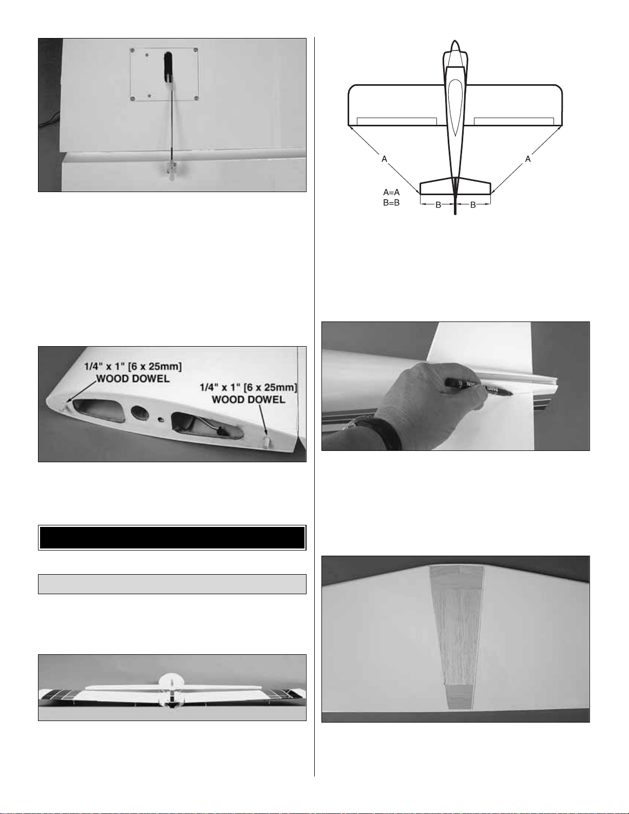
❏ 2. Test fit the stab into the opening in the back of the
fuselage. Stand back and look at the stab in relation to the
wing.The stab should be parallel with the wing. If not, sand
the stab saddle until the stab and wing are aligned.
❏ 2. Measure the distance from the tip of the stab to the tip of
each wing. Adjust the position of the stab until both are equal.
❏ 3.Using a fine-tip marker, trace the outline of the fuselage
onto the top and bottom of the stab.
❏ 4. Remove the stab from the fuselage. Use a sharp #11
blade or the expert tip that follows to cut the covering inside
the lines you have drawn.Use caution not to cut through the
surface of the wing skin. Remove the covering.
Install the Stab, Elevators & Rudder
ASSEMBLE THE FUSELAGE
10
 Loading...