

Page 1
WARRANTY
Great Planes
®
Model Manufacturing Co. guarantees this kit to be free from defects in both material and workmanship at the date of
purchase.This warranty does not cover any component parts damaged by use or modification. In no case shall Great Planes’ liability
exceed the original cost of the purchased kit. Further, Great Planes reserves the right to change or modify this warranty without notice.
In that Great Planes has no control over the final assembly or material used for final assembly, no liability shall be assumed nor
accepted for any damage resulting from the use by the user of the final user-assemb led product.By the act of using the user-assembled
product, the user accepts all resulting liability.
If the buyer is not prepared to accept the liability associated with the use of this product, the buyer is advised to return this
kit immediately in new and unused condition to the place of purchase.
READ THROUGH THIS MANUAL BEFORE
STARTING CONSTRUCTION. IT CONTAINS
IMPORTANT WARNINGS AND INSTRUCTIONS
CONCERNING THE ASSEMBLY AND USE OF
THIS MODEL.
GPMZ0237 for GPMA1355 V1.0© Copyright 2002
1610 Interstate Drive Champaign, IL 61822
(217) 398-8970, Ext 2
airsupport@greatplanes.com
INSTRUCTION MANUAL
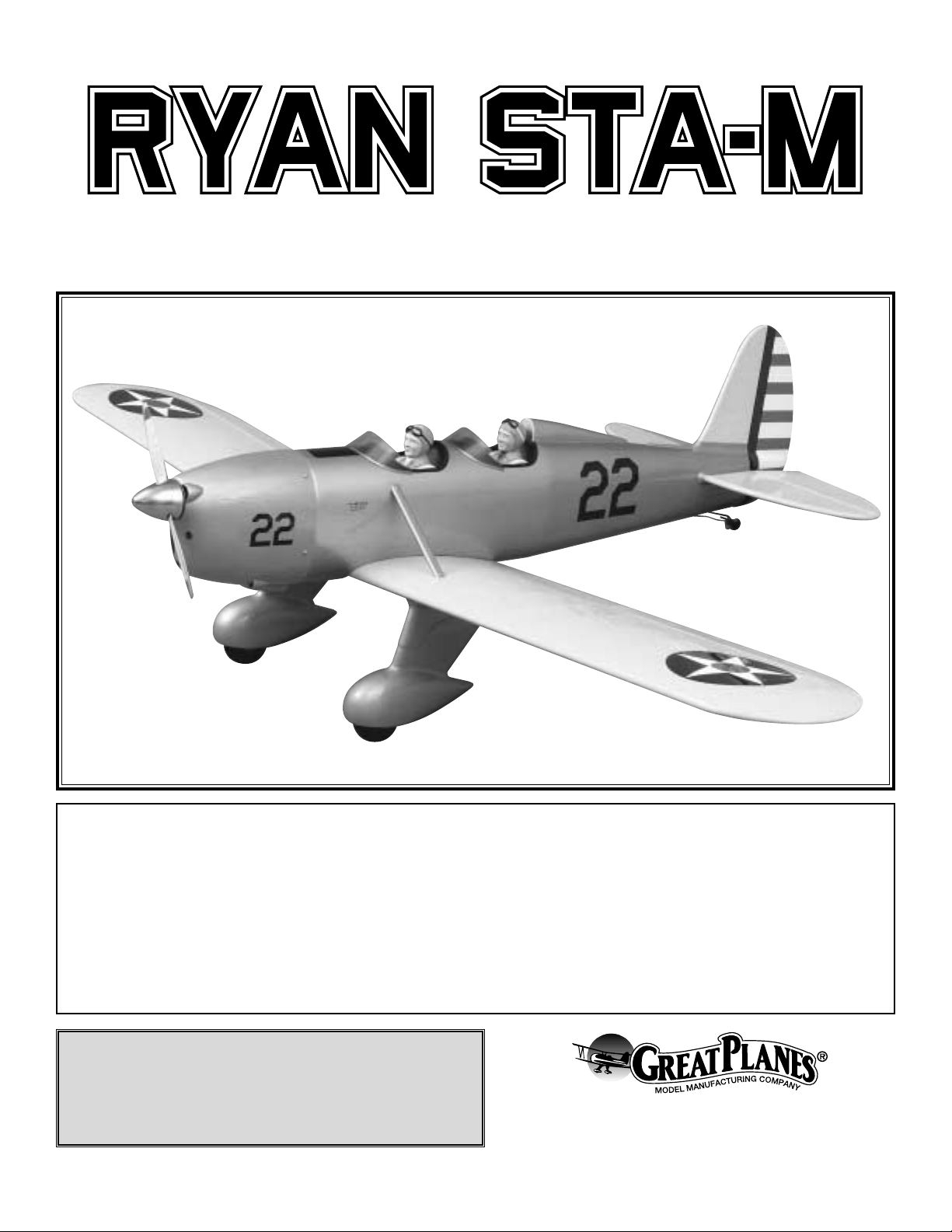
A. R. F.
Almost Ready to Fly
Wingspan: 82 in [2080mm]
Wing Area: 1066 sq in [69 dm
2
]
Weight: 10.25 - 11.5 lbs [4650 - 5220g]
Wing Loading: 22 - 25 oz/sq ft [67 - 76 g/dm2]
Length: 60 in [1525mm]
Radio: 4-5 channel with six servos
Engine: .61 - .91 cu in [10 - 15cc] two-stroke, .91 - 1.20 cu in [15 - 20cc] four-stroke
Page 2

INTRODUCTION................................................................2
IMAA...................................................................................2
Scale competition...............................................................3
SAFETY PRECAUTIONS..................................................3
DECISIONS YOU MUST MAKE ........................................4
Radio Equipment ................................................................4
Engine Recommendations.................................................4
Spinner Adapter Kit............................................................4
ADDITIONAL ITEMS REQUIRED.....................................4
Hardware and Accessories................................................4
Adhesives and Building Supplies.......................................4
Optional Supplies and Tools...............................................5
IMPORTANT BUILDING NOTES.......................................5
KIT CONTENTS .................................................................6
ORDERING REPLACEMENT PARTS ...............................7
TIGHTEN THE COVERING................................................8
ASSEMBLE THE WING.....................................................8
Hinge the Ailerons..............................................................8
Hook Up the Ailerons.........................................................9
Join the Wing......................................................................9
Mount the Landing Gear ..................................................10
ASSEMBLE THE FUSELAGE.........................................12
Mount the Stabilizer and Fin............................................12
Mount the Servos.............................................................15
Hook Up the Rudder ........................................................17
Hook Up the Elevators.....................................................18
Mount the Tailgear ............................................................20
Mount the Engine.............................................................21
Mount the Cowl................................................................22
Finish the Radio Installation.............................................24
SCALE DETAILS .............................................................24
Mount the Wing Struts......................................................24
Finish the Cockpits...........................................................25
Apply the Decals..............................................................27
PREPARE THE MODEL FOR FLYING ............................27
Set the Control Throws.....................................................27
Balance the Model Laterally.............................................28
Balance the Model (C.G.).................................................28
Identify Your Model...........................................................29
Charge the Batteries........................................................29
Balance Propellers...........................................................29
CHECKLIST.....................................................................29
FINAL PREPARATIONS..................................................30
Ground Check..................................................................30
Range Check....................................................................30
ENGINE SAFETY PRECAUTIONS.................................30
AMA SAFETY CODE ......................................................30
General.............................................................................30
Radio Control ...................................................................31
FLYING.............................................................................31
Takeoff..............................................................................31
Flight.................................................................................31
Landing..............................................................Back Cover
Windscreen Template.....................................Back Cover
Congratulations and thank you for purchasing the Great
Planes Ryan STA-M ARF. We at Great Planes R&D were
pleased with the appearance and performance of the
original red, white and black civilian Ryan STA and are just
as pleased with this military “M” version. In fact, a couple of
minor improvements make this plane our best ARF yet.
Although not intended to be an all-out scale model, the
Ryan's classic design and two-cockpit layout make it
tempting for enthusiastic modelers to spend a few extra
hours adding even more details (such as cockpit controls,
flying wires, panel lines, etc.).
When it's time to fly your STA-M, you'll be as pleased with
its performance as you are with its appearance.During test
flying, it flew so well that we had to actually try to make bad
landings! And every time the Ryan went up, local R/C club
members stopped what they were doing to watch this model
fly. The ST A-M's g reatest attrib ute–and what y ou can expect
when you get your model in the air–is its nostalgic
gracefulness.Make sure you have plenty of fuel in your field
box because when it's time to fly, you'll be needing it.
For the latest technical updates or instruction manual
corrections to the Ryan STA-M, visit the web site listed below
and select the Great Planes Ryan STA-M ARF.If there is new
technical information or changes to this model, a “tech
notice” box will appear in the upper left corner of the page.
http://www.greatplanes.com/airplanes/index.html
The Great Planes Ryan STA-M is an excellent sport-scale
model and is eligible to fly in IMAA (International Miniature
Aircraft Association) events. The IMAA is an organization
that promotes non-competitive flying of giant-scale models.
If you plan to attend an IMAA event, contact the IMAA for a
copy of the IMAA Safety Code at the address or telephone
number below.
IMAA
205 S. Hilldale Road
Salina, KS 67401
(913) 823-5569
IMAA Information
INTRODUCTIONTABLE OF CONTENTS
2
Page 3
Though the Great Planes Ryan STA-M is an ARF and may
not have the same level of detail as an “all-out” scratch-built
model, it is a scale model none-the-less and is therefore
eligible to compete in the Fun Scale class in AMA
competition (we receive many favorable reports from those
who fly Great Planes ARFs in scale competition!). In
Fun
Scale
, the “builder of the model” rule does not apply. To
receive the five points f or scale documentation, the only proof
required that a full size aircraft of this type in this
paint/markings scheme did exist is a single sheet such as a
kit box cover from a plastic model, a photo, or a profile
painting, etc. If the photo is in black and white, other written
documentation of color must be provided. Contact the AMA
for a rule book with full details.
If you would like photos of the full-size Ry an STA-M for scale
documentation, or if you would like to study the photos to
add more scale details, photo packs are available from:
Bob's Aircraft Documentation
3114 Y uk on Av e
Costa Mesa, CA 92626
Telephone: (714) 979-8058
Fax:(714) 979-7279
e-mail: www.bobsairdoc.com
1. Your Ryan STA-M should not be considered a toy, but
rather a sophisticated, working model that functions very
much like a full-size airplane. Because of its performance
capabilities, the Ryan STA-M, if not assembled and operated
correctly, could possibly cause injury to yourself or
spectators and damage to property.
2. You must assemble the model according to the
instructions. Do not alter or modify the model, as doing so
may result in an unsafe or unflyable model. In a few cases
the instructions may differ slightly from the photos.In those
instances the written instructions should be considered
as correct.
3. You must take time to build straight, true and strong.
4. You must use an R/C radio system that is in first-class
condition and a correctly sized engine and components (fuel
tank, wheels, etc.) throughout the building process.
5. You must correctly install all R/C and other components so
that the model operates correctly on the ground and in the air .
6. You must check the operation of the model before every
flight to insure that all equipment is operating and that the
model has remained structurally sound. Be sure to check
clevises or other connectors often and replace them if they
show any signs of wear or fatigue.
7. If you are not already an experienced R/C pilot, you
should fly the model only with the help of a competent,
experienced R/C pilot.
8. While this kit has been flight tested to exceed normal use,
if the plane will be used for extremely high stress flying, such
as racing, the modeler is responsible for taking steps to
reinforce the high stress points.
9. WARNING: The cowl and wheel pants included in this kit
are made of fiberglass, the fibers of which may cause eye,
skin and respiratory tract irritation. Never blow into a part to
remove fiberglass dust, as the dust will blow back into your
eyes. Always wear safety goggles, a particle mask and
rubber gloves when grinding, drilling and sanding fiberglass
parts. Vacuum the parts and work area thoroughly after
working with fiberglass parts.
Remember:Take y our time and follow the instructions to
end up with a well-built model that is straight and true.
If you have not flown a low-wing model before, we
recommend that you get the assistance of an experienced
pilot in your R/C club for your first flights. If you're not a
member of a club, your local hobby shop has information
about clubs in your area whose membership includes
experienced pilots.
In addition to joining an R/C club, we strongly recommend y ou
join the AMA (Academy of Model Aeronautics). AMA
membership is required to fly at AMA sanctioned clubs.There
are over 2,500 AMA chartered clubs across the country.
Among other benefits, the AMA provides insurance to its
members who fly at sanctioned sites and events .Additionally,
training programs and instructors are available at AMA club
sites to help you get started the right way. Contact the AMA at
the address or toll-free phone number below:
Academy of Model Aeronautics
5151 East Memorial Drive
Muncie, IN 47302-9252
Tele. (800) 435-9262
Fax (765) 741-0057
Or via the Internet at:
http://www.modelaircraft.org
We, as the kit manufacturer, provide you with a top quality
kit and instructions, but ultimately the quality and flyability
of your finished model depends on how you build it;
therefore, we cannot in any way guarantee the
performance of your completed model and no
representations are expressed or implied as to the
performance or safety of your completed model.
PRO TECT YOUR MODEL,YOURSELF
& OTHERS...FOLLOW THESE
IMPORTANT SAFETY PRECAUTIONS
Scale Competition
3
Page 4

Though technically the Ryan STA-M is considered a
“giant-scale” model, it does not require the same “heavyduty”equipment as other truly giant planes.The only “heavyduty” equipment suggested for this model is three servos
that have 50 oz.-in. [3.3 kg-cm] or more of torque (one for
the rudder and two for the elevators). The ailerons and
throttle may be operated by standard servos.
Because the Ryan STA-M uses dual elevator servos and
because the servos must move in opposite directions (due to
the way they are mounted in the fuse), they cannot be
connected with a “Y” connector (unless you have a “reverse”
servo).Therefore, to fly the Ryan, a radio system capable of
electronic servo mixing is required, so that one of the
elevator servos can be reversed. If you do not have a radio
with programmable mixing, the Futaba®SR-10 Synchronized
Servo Reverser (FUTM4150) may be used. When both
elevator servos are connected to this device, they operate in
opposite directions. The Synchronized Servo Reverser is
compatible with most popular radio systems.
A receiver battery with a capacity of at least 1000 mAh is
also recommended for this model.
There are several engines that will work well in the Ryan
STA-M ARF.The official engine size recommendation range is
.61 - .91 cu in [10.0 - 15.0cc] two-stroke or .91 - 1.20 cu in
[15.0 - 20.0cc] four-stroke.If an engine in the upper end of the
size range is selected, remember that this is a scale model
that is intended be flown in a scale manner at scale speeds,
so prudent throttle management must be practiced. Our
prototype, powered by an O.S.®MAX .91 FS with a 14 x 6
prop, flew smoothly and most scale-like at about 3/4 throttle.
Refer to your engine manuf acturer's recommendations for the
correct size propeller.Note:With the O.S.MAX .91 four-stroke
used in this model, the O.S. “in” type exhaust header pipe
(OSMG2624) was used to position the muffler so an exhaust
hole did not have to be cut in the cowl.
This kit includes a 2-3/4" aluminum spinner with a 10-32
spinner bolt. Due to the variety of engines that may be used
on the Ryan, an adapter kit for mounting the spinner is not
included with this kit and must be purchased separately. For
the O.S. .61 SF, SX and other two-stroke engines with a
5/16"-24 crankshaft thread purchase Spinner Adapter Kit
#GPMQ4584.For the O.S ..91 to 1.20 four-strokes and other
four-strokes with a 5/16"-24 crankshaft thread purchase
Spinner Adapter Kit #GPMQ4588.If neither of these adapter
kits will suit your engine, another brand of adapter kit (that
includes both the prop nut and the spacer ring for the back
plate of the spinner - such as Tru-Turn) must be purchased.
In addition to the items listed in the “Decisions You Must
Make” section, following is the list of hardware and
accessories required to finish the Ryan. Order numbers are
provided in parentheses.
❏ (2) 24" [610mm] Servo extensions for ailerons
(HCAM2200 or HCAM2721 for Futaba®)
❏ (1) 6" [150mm] Servo extension for aileron (HCAM2000
or HCAM2701 for Futaba)
❏ (1) “Y” connector for ailerons (FUTM4130 for Futaba)
❏ Suitable propeller and spare propellers
❏ Medium Fuel Tubing (GPMQ4131)
❏ Switch & Charge Jack Mounting Set (GPMM1000)
❏ Fuel filler valve for glow fuel (GPMQ4160)
❏ R/C foam padding (1/4" [6mm] HCAQ1000, or 1/2"
[13mm] HCAQ1050)
❏ (2) Williams Bros. #62500 1/4-scale Standard pilots
(WBRQ2625)
❏ Olive Drab paint for cockpit and paint for pilots
❏ Model Products #021 Remote glow plug adapter
(MODP1221)
❏ 1/4" [6mm] Kwik Stripe silver striping tape (GPMQ1244)
❏ #64 rubber bands (for mounting fuel tank)
In addition to common household tools and hobby tools, this
is the “short list”of the most important items required to build
the Ryan.
Great Planes Pro™CA and Epoxy glue
are recommended.
❏ 1/2 oz. Thin CA (GPMR6002)
❏ 1/2 oz. Medium CA (GPMR6008)
❏ CA Applicator Tips (HCAR3780)
❏ 30-Minute Epoxy (GPMR6047)
❏ Milled Fiberglass (GPMR6165)
❏ Threadlocker (GPMR6060)
❏ 50" [1270mm] of K&S #801 Kevlar thread (K+SR4575) or
non-elastic monofilament line for stab alignment
❏ Builders Triangle Set (HCAR0480) (for fin alignment)
❏ Masking T ape (TOPR8018)
❏ Silver solder (GPMR8070)
❏ Small metal file
❏ English size drill bits: 1/16", #48 (or 5/64"), 3/32", #36 (or
7/64"), 1/8", #29 (or 9/64"), 5/32", 3/16", 7/32", 17/64" (or
Adhesives and Building Supplies
Hardware and Accessories
ADDITIONAL ITEMS REQUIRED
Spinner Adapter Kit
Engine Recommendations
Radio Equipment
DECISIONS YOU MUST MAKE
4
Page 5
1/4") -or- Metric size drill bits: 1.6mm, #48 (or 2mm),
2.4mm, #36 (or 2.8mm), 3.2mm, #29 (or 3.6mm), 4mm,
4.8mm, 5.6mm, 6.7 (or 6.4mm),
❏ 6-32 tap (or Great Planes 6-32 tap and drill set with #36
drill - GPMR8102)
❏ 8-32 tap (or Great Planes 8-32 tap and drill set with #29
drill - GPMR8103)
❏ 3/16" brass tube
❏ Coverite
™
21st Century®sealing iron (COVR2700)
❏ Coverite
™
21st Century iron cover (COVR2702)
❏ Coverite
™
21st Century trim seal iron (COVR2750)
❏ Denatured Alcohol (for epoxy clean up)
Here is a list of optional items mentioned in the manual that
will help you assemble the Ryan.
❏ CA Debonder (GPMR6039)
❏ CA Activator (GPMR6034)
❏ 6-Minute Epoxy (GPMR6045)
❏ Microballoons (TOPR1090)
❏ Epoxy Brushes (GPMR8060)
❏ Mixing Sticks (GPMR8055)
❏ Hobby Knife (HCAR0105), #11 Blades (HCAR0211)
❏ Easy-Touch
™
Bar Sander (GPMR6170 or similar)
❏ Felt-Tip Marker (TOPQ2510)
❏ Rotar y tool such as a Dremel
®
❏ Reinforced cut-off wheel (GPMR8020)
❏ Curved Tip Canopy Scissors for Trimming Plastic Parts
(HCAR0667)
❏ Dead Center
™
Engine Mount Hole Locator (GPMR8130)
❏ Great Planes AccuThrow
™
Deflection Gauge (for
measuring control throws, GPMR2405)
❏ Flat Black MonoKote
®
film for optional anti-glare panel (6'
roll - TOPQ0508)
❏ 5/32" brass tube
• There are two types of screws used in this kit:
Sheet metal screws are designated by a number and a
length. For example #6 x 3/4" [19mm]
This is a number six screw that is 3/4" [19mm] long.
Machine screws are designated by a number, threads per
inch and a length. For example 4-40 x 3/4" [19mm]
This is a number four screw that is 3/4" [19mm] long
with forty threads per inch.
• When you see the term
test fit
in the instructions, it
means that you should first position the part on the
assembly without using any glue, then slightly modify or
custom fit
the part as necessar y for the best fit.
• Whenever the term
glue
is written you should rely upon
your experience to decide what type of glue to use.When a
specific type of adhesive works best for that step, the
instructions will make a recommendation.
• Whenever just
epoxy
is specified you may use
either
30-minute (or 45-minute) epoxy or6-minute epoxy. When
30-minute epoxy is specified it is highly recommended that
you use only 30-minute (or 45-minute) epoxy, because you
will need the working time and/or the additional strength.
• Photos and sketches are placed before the step they
refer to. Frequently you can study photos in following steps
to get another view of the same parts.
• The Ryan STA-M is factory-covered with Top Flite
MonoKote film. Should repairs ever be required, MonoKote
can be patched with additional MonoKote purchased
separately. MonoKote is packaged in six-foot rolls, but some
hobby shops also sell it by the foot. If only a small piece of
MonoKote is needed for a minor patch, perhaps a fellow
modeler would give you some. MonoKote is applied with a
model airplane covering iron, but in an emergency a regular
iron could be used. A roll of MonoKote includes full
instructions for application.Following are the colors used on
this model and order numbers for six foot rolls.
Aluminum (TOPQ0205)
Cub Yellow (TOPQ0220)
True Red (TOPQ0227)
Insignia Blue (TOPQ0207)
White (TOPQ0204)
IMPORTANT BUILDING NOTES
Optional Supplies and Tools
5
Page 6
6
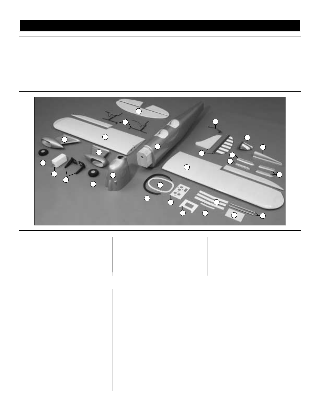
1 Wing with Ailerons
2 Fuselage
3 Stab with Elevators
4 Fin with Rudder
5 Cowl
6 Cowl Ring
7 Wheel Pants
8 Rudder Fairing
9 T urtledeck
10 Fin Fairing
11 Stab Fairings
12 Wing Bolt Plate
13 Forward Wing Joiners
14 Wing Str uts
15 Dorsal Fin
16 Engine Mount
17 Fuel Tank
18 Cockpit Coaming
19 Main Landing Gear
20 Tailgear
21 Aft Wing Joiner
22 Forward Servo Tray
23 Aft Servo Tray
24 Main Wheels
(1) 2-3/4" [70mm] spinner
(2) Decal sheets
(1) CA hinge strip
(2) 2-56 x 6" [150mm] pushrods (ailerons)
(4) Large control horns (ailerons, elevators)
(38) #2 x 1/2" [13mm] screws
(2) Nylon Faslinks (ailerons)
(3) Nylon clevises (ailerons - 2, throttle - 1)
(7) Silicone clevis retainers (clevises)
(8) 1/8" [3mm] flat nylon straps (main LG)
(4) 3 x 6mm socket head cap screws (LG axles)
(4) 5mm wheel collars (main wheels)
(4) 3mm set screws for wheel collars
(2) 4-40 x 36" [910mm] wire pushrods (elevators)
(4) 2-56 x 3/4" [19mm] screws (elev cntrl horns)
(2) Large metal solder clevises (elevators)
(2) 4-40 metal threaded clevises (elevators)
(2) 4-40 nuts (for clevises)
(1) 6-32 x 1-1/2" [38mm] threaded rod (rudder)
(2) 4-40 nylon torque rod horns (rudder)
(2) 1/8" [3mm] nylon hump straps (tail gear)
(1) 36" [910mm] gray inner pushrod tube (tail
gear, antenna tube)
(1) 3/16" x 36" [910mm] pshrd tube (tail steering)
(1) 2-56 x 36" [910mm] wire pshrd (tail steering)
(2) brass screw-lock connector body
(2) 4-40 x 1/8" [3mm] screws (for screw-lock)
(2) nylon retainers (for screw-lock)
(1) nylon ball link (tail steering)
(1) 0-80 threaded ball (tail steering)
(1) 0-80 nut (for threaded ball)
(2) 1/4-20 blind nuts (factory installed)
(2) 1/4-20 x 2" [50mm] nylon wing bolts
(8) #4 x 5/8" [16mm] scrws (cwl mnt, wing struts)
(4) #4 washers (cowl mounting)
(4) #4 lock washers (cowl mounting)
(6) #2 washers (servo tray)
(1) 2-56 x 18" [460mm] wire pushrod (throttle)
(1) 3/16" x 12" [21 x 305mm] pushrod tube
(1) 1/4" x 1/2" x 6" [6 x 13 x 150mm] balsa stick
(2) 1/4" x 3/8" x 6-1/4" [6 x 10 x 160mm]
hardwood sticks
(2) Axles
(4) 1/32" x 3/4" [1 x 20mm] plywood discs
(8) 8-32 x 1" [25mm] socket head cap screws
(4) #8 washers (engine mount)
(8) #8 lock washers (eng mnt, eng mounting)
(4) 8-32 blind nuts (engine mount)
(4) Cowl mount blocks
(2) Windscreens
(2) Wing dowels
Rudder pull/pull components:
(1) Metal cable
(4) copper swages
(4) 2mm metal clevises
(4) 2mm brass couplers
(4) 2mm nuts
(4) silicone clevis retainers
Kit Contents (Photographed)
Kit Contents (Not Photographed)
Before starting to build, use the Kit Contents list to take an inventory of this kit to make sure it is complete and inspect
the parts to make sure they are of acceptable quality. If any parts are missing or are not of acceptable quality, or if you
need assistance with assembly, contact Great Planes Product Support. When reporting defective or missing parts, use
the part names exactly as they are written in the Kit Contents list on this page.
Great Planes Product Support:
Phone: (217) 398-8970
Fax: (217) 398-7721
E-mail: airsupport@greatplanes.com
KIT CONTENTS
3
24
17
7
16
24
19
1
2
7
1
5
6
18
22
23
20
4
13
21
10
15
12
8
9
11
14
Page 7

7
To order replacement parts for the Great Planes Ry an STA-M ARF, use the order numbers in the Replacement Parts List
that follows. Replacement par ts are available only as listed. Not all parts are available separately (an aileron cannot be
purchased separately, but is only available with the wing kit).Replacement parts are not available from Product Support,
but can be purchased from hobby shops or mail order/Internet order firms. Hardware items (screws, nuts, bolts) are also
available from these outlets. If you need assistance locating a dealer to purchase par ts, visit www.greatplanes.com and
click on “Where to Buy.” If this kit is missing parts, contact Great Planes Product Support.
Replacement Parts List
Order Number Description
How to Purchase
Missing pieces ................................................Contact Product Support
Instruction manual...........................................Contact Product Support
Full-size plans.................................................Not available
Kit parts listed below .......................................Hobby Supplier
GPMA2280 ...........Wing Kit (R&L wing panels, R&L ailerons, hinge strip, 3 pc.ply forward wing
joiner, ply aft wing joiner, (2) wing dowels, wing bolt plate.)
GPMA2281 ...........Fuselage Kit (Fuselage, forward and aft servo trays, (4) hardwood cowl
mounting blocks, (2) cockpit coaming, (2) 1/4" x 3/8" x 6-3/8" [7 x 10 x
165mm] hardwood forward servo mount rails, 1/4" x 1/2" x 6" [6 x 13 x
150mm] balsa rudder pushrod tube support, (2) hardwood wing strut
mounting blocks.)
GPMA2282 ...........Tail Set (Fin & rudder, stab & elevators, hinge strip.)
GPMA2283 ...........Cowl (Fiberglass cowl, plywood cowl ring, (4) ply cowl discs.)
GPMA2284 ...........Windscreen Set (2)
GPMA2205 ...........Main Landing Gear Set (L&R)
GPMA2286 ...........Wheel Pants (L&R)
GPMA2287 ...........Wing Strut Set (2)
GPMA2288 ...........Axle Set ((2) axles, (4) wheel collars, screws, wrenches)
GPMA2289 ...........Rudder Pull-Pull Set (Braided rudder cable, (4) threaded brass couplers,
(4) metal clevises, (4) 2mm nuts, (4) copper swages.)
GPMA2290 ...........Decal Sheet Set (2 sheets)
GPMA2291 ...........Plastic Parts Set (Tur tledeck, stab & fin fairings, R&L rudder fairing.)
GPMA2292 ...........Tailgear Set w/Wheel
ORDERING REPLACEMENT PARTS
0" 1" 2" 3" 4" 5" 6" 7"
0 10 20 30 40 50 60 70 80 90 100 110 120 130 140 150 160 170 180
Inch Scale
Metric Scale
To convert inches to millimeters, multiply inches by 25.4
Page 8
1. If you have not done so already, remove the major parts
of the kit from the box (wings, fuse, wheel pants, cowl, tail
parts, etc.) and inspect them for damage. If any parts are
damaged or missing, contact Product Support at the
address or telephone number listed on page 6.
2. Remove the masking tape and separate the ailerons from
the wing, the rudder from the fin, and the elevators from the
stab. If necessar y, use a covering iron with a covering sock
on high heat to tighten the covering. Apply pressure over
sheeted areas to thoroughly bond the covering to the
wood. Hint: Poke three or four pin holes in the covering
between the “ribs” in the tail surfaces and ailerons.This will
allow air to escape to fully tighten the covering.
Do the right aileron first.
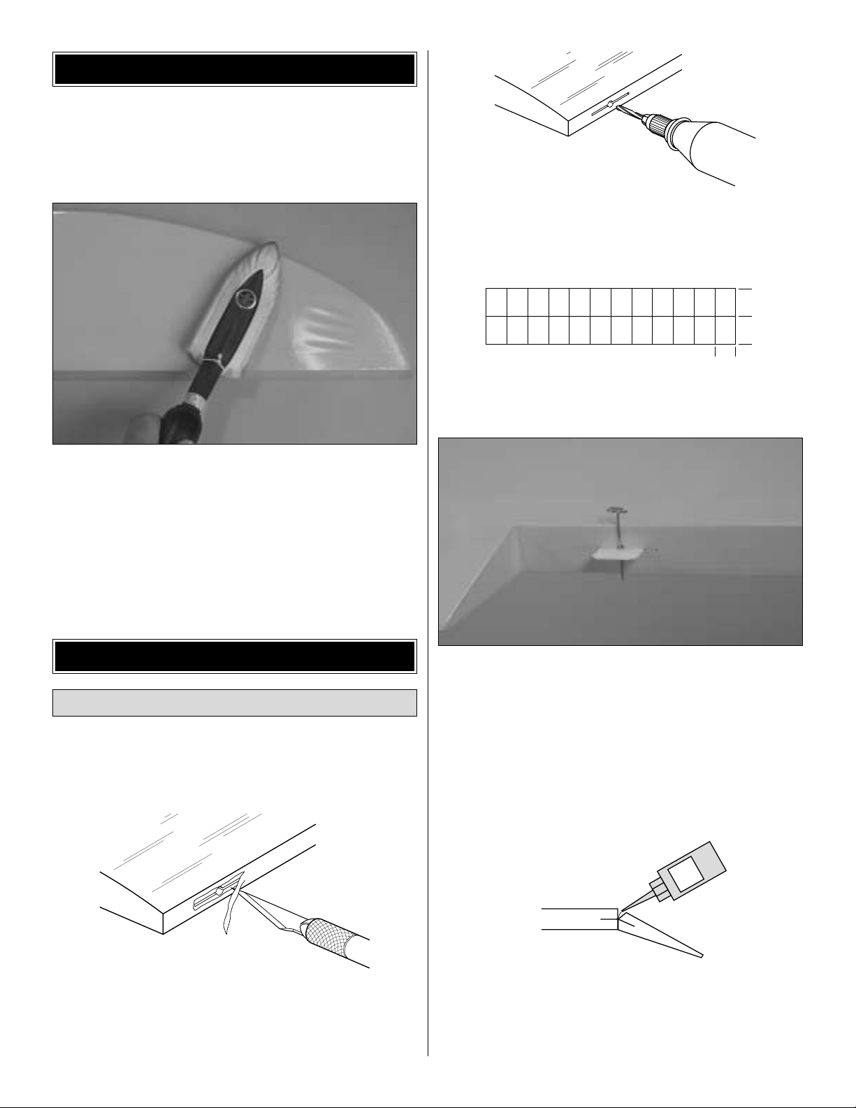
❏❏1.Locate the hinge slots in the right wing and the right
aileron. Cut a small strip of covering from each slot.
❏❏2. Drill a 3/32" [2.4mm] hole 1/2" [13mm] deep in the
center of the slots.For the best result, use a high-speed tool
such as a Dremel. Inser t a #11 knife blade into the slots,
working it back and forth a few times to clean the slots out.
❏❏3. Cut four 3/4" x 1" [19 x 25mm] hinges from the
supplied CA hinge strip.
❏❏4.Test fit the aileron to the wing with the hinges .If the
hinge slots are too tight, remove the hinges and use a #11
blade to slightly open the slots. If necessary, insert a pin
through the center of the hinges so they remain centered
when joining the aileron to the wing.
❏❏5.With the aileron joined to the wing, remove any pins
used to center the hinges. Be certain there is a small gap
between the leading edge of the aileron and the wing–just
enough to slip a piece of paper through or to see light through.
❏❏6. Apply six drops of thin CA to both sides of all the
hinges. Wait a few seconds between drops to allow the
hinge slots to fully absorb the CA.
❏ 7.Join the left aileron to the left wing panel the same way.
1"
1"
3/4"
DRILL A 3/32" HOLE
1/2" DEEP, IN CENTER
OF HINGE SLOT
AWAY FROM THE SLOT
CUT THE COVERING
Hinge the Ailerons
ASSEMBLE THE WING
TIGHTEN THE COVERING
8
CA
THIN
Page 9
Start with the right aileron.
❏❏1. Cut the covering from the right aileron servo mount
in the bottom of the wing. Hint: Cut the covering 1/8" [3mm]
inside the edges, then use a trim iron to seal the covering to
the edges.
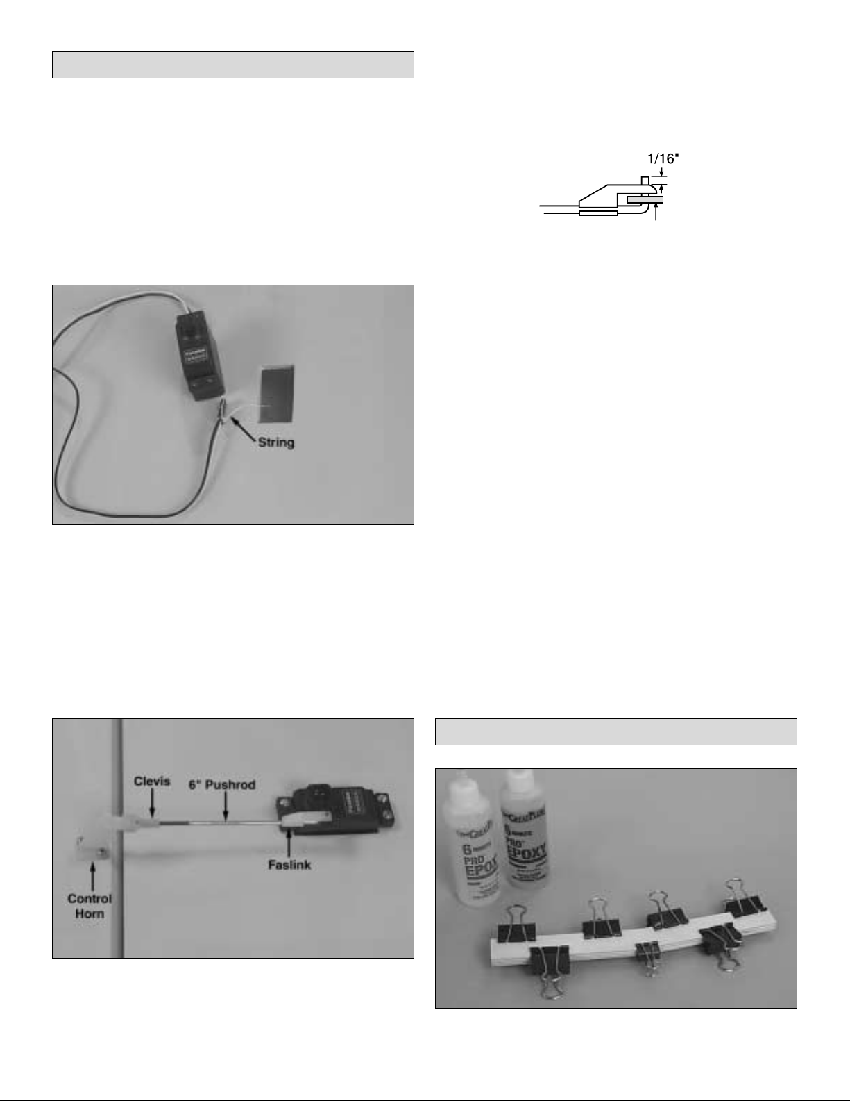
❏❏2.Connect a servo extension cord to the aileron servo
wire. Secure the connection with vinyl tape, heat shrink
tubing, or special clips suitable for that purpose.
❏❏3. Tie the end of the string that is taped inside the
wing to the end of the servo wire. Pull the wire through.
Note: If something happens to the string such as it breaks
or it cannot be located, don't worry. Tie another piece of
string to the servo wire and tie a weight (such as a wheel
collar) to the other end of the string. Place the wing on end
and drop the weight down through the holes in the ribs.Pull
the end of the string out of the hole in the middle of the wing.
Refer to this photo for the following two steps.
❏❏4.Drill 1/16" [1.6mm] holes in the wing for mounting the
aileron servo. Add a few drops of thin CA to the holes and
allow to harden.Mount the servo to the wing.Note that, for the
right aileron servo shown in the photo, the servo arm points
towards the middle of the wing and the output shaft is toward
the trailing edge.The left aileron servo is mounted in a “mirror”
image (with the servo arm pointing toward the middle of the
wing and the output shaft toward the trailing edge).
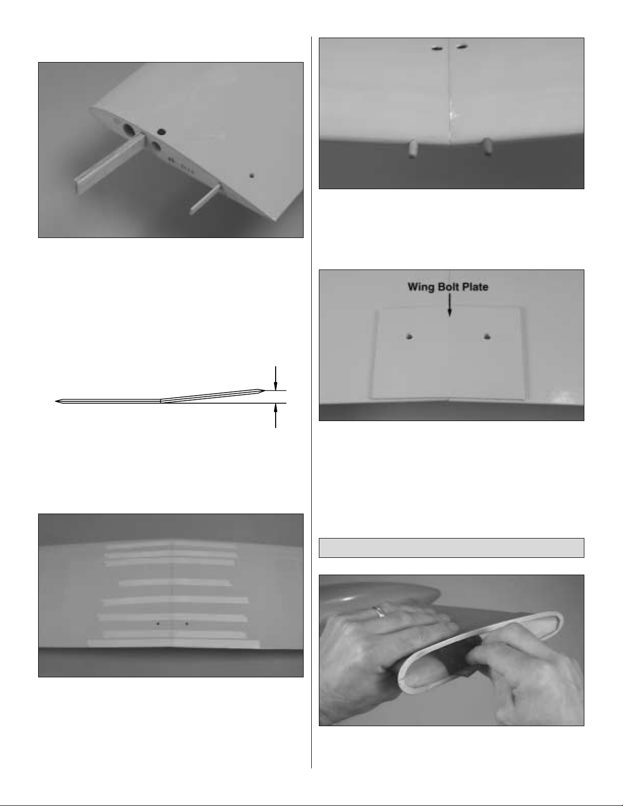
❏❏5. Thread a nylon clevis twenty full turns onto a 6"
[150mm] threaded pushrod. Connect the clevis to a control
horn with a silicone retainer over the clevis.Place the control
horn on the aileron so the pushrod is in alignment with the
servo arm. Use a felt-tip pen to mark the pushrod over the
holes in the servo arm. Bend the pushrod at the mark, then
fit a nylon Faslink (shown in the sketch above) to the
pushrod.Cut the pushrod so 1/16" [2mm] protrudes from the
Faslink.If necessary, enlarge the holes in the servo arm with
a #48 (or 5/64" [2mm]) drill. Connect the pushrod to the
servo arm with the Faslink.
❏❏6. Drill 1/16" holes into the aileron for mounting the
control horn with two #2 x 1/2" [13mm] screws. Add a few
drops of thin CA to the holes and allow to fully harden.
Mount the control horn to the aileron with two #2 x 1/2"
[13mm] screws.Be certain the screws are secure and get a
good “bite” into the wood. If necessary, remove the screws,
add a few more drops of thin CA to the holes and allow to
harden. Remount the control horn.
❏ 7. Mount the left aileron servo and make the pushrod
the same way. Install the screws that hold the servo arms to
the servos.
❏ 1. Use epoxy to glue the three plywood forward wing
joiners together.Wipe away excess epo xy bef ore it hardens.
Join the Wing
Hook Up the Ailerons
9
Servo Arm
Page 10
Refer to this photo for the following two steps.
❏ 2. Cut the covering from the pre-drilled holes in both wing
halves for the servo wires, the wing dowels and the wing
bolts. Guide the end of the ser vo wires through the holes in
the top of both wing halves.
❏ 3. Test fit the forward wing joiner and the plywood aft
wing joiner in both wing halves. Make adjustments where
necessary for a good fit.
❏ 4. Test fit the wing halves together. There should be no
gap.When one wing is lying flat on the workbench, the tip of
the other wing should be approximately 6-5/8" [168mm] from
the workbench. Make adjustments where necessary.
❏ 5.Separate the wings and remove the joiners.Thoroughly
coat all mating surfaces, including the inside of the wings
where the joiners fit, with 30-minute epoxy, then glue the wings
together.Use masking tape to tightly hold the wings together
until the epoxy has hardened. Excess epoxy that gets on the
covering can be easily removed bef ore it hardens with a tissue
dampened with denatured alcohol or other suitable solvent.
❏ 6. Round one end of both hardwood wing dowels. Use
epoxy to glue the dowels in the wing with the rounded ends
forward.Be certain approximately 1/2" [13mm] of the dowels
protrudes from the wing. While you've got some epoxy
mixed up, lightly coat the dowels to fuelproof them.
❏ 7. Use a shar p, new #11 blade to trim the covering from
the bottom of the wing for the 1/8" [3mm] plywood wing bolt
plate. Use care to cut just through the covering, while not
cutting into the wood. Glue the wing bolt plate into position.
After the glue hardens, use the holes in the top of the wing
as a guide to drill 17/64" [6.7mm] (or 1/4" [6.4mm]) holes
through the wing bolt plate.
❏ 1.Use coarse sandpaper to roughen the inside of the
rim
near the front and back of both wheel pants. The areas
specified are indicated by the brack ets in the following photo .
Mount the Landing Gear
6-5/8"
10
Page 11

❏ 2. Apply a fillet of epoxy mixed with milled fiberglass
inside the pants where shown between the brackets in the
photo.If milled fiberglass is not available, microballoons is a
suitable substitute.
Start with the right gear first so the photos will
match your progress the first time through.
❏❏3. Mount an axle onto the r ight landing gear wire with
two 3 x 6mm SHCS (socket-head cap screws). The axle
should be positioned so that it is parallel with the bottom
horizontal wires.Tighten and loosen the screws a few times
to mark the wire.
❏❏4. Remove the axle from the landing gear. File flat
spots on the gear where the screws made their marks.
❏❏5.Reposition the axle on the gear.Tighten the screws.
Be certain that the screws have “landed” on the flat spots
and that the axle has remained parallel with the bottom
wires.If necessary, remo v e the axle and adjust the flat spots
until you can get the axle positioned correctly.
(Taking your
time here and doing the job correctly will eliminate having
the axles loosen at the flying field.)
❏❏6. Cut the covering from the grooves in the landing
gear rails in the bottom of the right wing panel. Trim the rail
and the wing sheeting (where indicated by the arrow) to
accommodate the aft strut where it “angles up” toward the
main strut. Also trim the edge of the hole in the forward rail
to accommodate the bend in the main strut.
❏❏7. Fit the landing gear into the wing. Drill 1/16"
[1.6mm] holes for the screws for four landing gear straps
where shown, then mount the gear to the wing with the
straps and #2 x 1/2" [13mm] screws.Note: Make certain the
straps are no closer than 1" [25mm] to the forward strut.
❏❏8. Fit the right wheel pant over the gear. (The right
wheel pant is the one that fits the right wing best when fit
over the landing gear.) Slip a wheel collar followed by a
wheel and another wheel collar onto the axle (if necessary,
temporarily remove the axle to install the wheel).
❏❏9. Center the wheel pant and the wheel laterally on the
gear. Also position the pant, fore and aft, where it best fits the
wing.Note: If the landing gear wire protrudes below the bottom
surface of the wing and interferes with the fit of the wheel pant,
trim the wheel pant as necessary to accommodate the wire.
Flat Spot
11
Page 12

❏❏10. Drill a 1/16" [1.6mm] hole through the wheel pant
into the landing gear block as shown in the photo and where
indicated in the sketch. Enlarge the hole in the wheel pant
only with a 3/32" [2.4mm] drill, then mount the wheel pant
to the wing with a #2 x 1/2" [13mm] screw.
❏❏11. One at a time, drill the remaining three holes
and mount the wheel pant to the wing with three more
#2 x 1/2" [13mm] screws.
❏❏12. Remove the wheel from the axle. File a flat spot
on the axle for the set screw in the outer wheel collar. Add a
few drops of oil to the axle. Using a drop of thread locking
compound on the 3mm set screws, mount the wheel to the
axle with the wheel collars.
❏❏13.Temporarily remove the screws that hold the axle
to the landing gear wire, add a drop of threadlocker to the
threads, then reinstall the screws and tighten them securely.
❏ 14. Return to step 1 and mount the left landing gear and
wheel pant to the wing the same way.
While working on the fuse, it helps to have a building stand.
We use a Robart Super Stand II (ROBP1402).
❏ 1. The same as was done for the ailerons and the wing,
prepare the elevator, stab, rudder and fin for hinging by
cutting a strip of covering from the hinge slots and drilling
holes. Do not glue in the hinges until instr ucted to do so.
❏ 2.Trim the covering from the fuselage over the slots for
the stab and fin and over the holes for the rudder control
cables. Also trim the covering from the openings in the
elevator pushrod tubes (one on each side of the fuselage,
indicated by the arrow in the photo).
❏ 3. Temporarily install the stab in the fuse.
❏ 4. Bolt the wing to the fuselage with two 1/4-20 x 2"
[50mm] nylon wing bolts.
❏ 5. Stand approximately ten feet behind the model and
view the stab and wing. If the stab and wing align with each
other proceed to the next step. If the stab and wing do not
align but are close, place a small weight on the “high side” of
the stab to see if you can bring it into alignment. If weight is
Mount the Stabilizer and Fin
ASSEMBLE THE FUSELAGE
Top of Wheel Pant Where
It Contacts the Wing
Landing Gear
Straps
Landing Gear
Blocks
12
Page 13

not enough, remove the stab from the fuselage.Lightly sand
the slots in the fuselage as necessary to get the stab to align
with the wing. Reinsert the stab and check the alignment.
❏ 6.Remove the wing from the fuse.Center the trailing edge
of the stab in the fuse by taking accurate measurements from
both tips to the sides of the fuse.
❏ 7. Tur n the fuse upside-down. Stick a T-pin through the
bottom of the fuse centered over the middle stringer. Tie a
small loop in one end of a 50" [1270mm] piece of non-elastic
string such as monofilament or Kevlar line (K+SR4575).Slip
the loop in the string over the T-pin.
❏ 8. Fold a piece of masking tape over the string near the
other end and draw an arrow on it. Slide the tape along the
string and align the arrow with one end of the stab as shown
in the photo.Swing the string over to the same position on the
other end of the stab. While keeping the stab centered from
side-to-side, adjust the stab and slide the tape along the string
until the arrow aligns with both ends of the stab.Be certain the
stab remains centered, side-to-side, during this process.
❏ 9. Use a fine-point felt-tip pen such as a Top Flite
®
Panel
Line Pen (TOPQ2510) to mark the outline of the fuse on the
top and bottom of the stab.
❏ 10. Remove the stab from the fuse. Use a sharp #11
hobby knife or follow the Expert Tip below to cut the
covering from the stab along the lines. Use care to cut only
into the covering and not into the wood. Cutting into the
balsa will weaken the structure.
How to cut covering from balsa.
To avoid cutting into the balsa, use a soldering iron instead
of a hobby knife to cut the covering.The tip of the soldering
iron doesn't have to be sharp, but a fine tip does work best.
Allow the iron to heat fully. Use a straightedge to guide the
soldering iron at a rate that will just melt the covering and not
burn into the wood. The hotter the soldering iron, the faster
it must move to melt a fine cut.
13
Page 14

❏ 11.Peel the covering from the stab.Remove any ink with
a piece of a tissue dampened with denatured alcohol.
❏ 12.Thoroughly coat all joining areas of the stab and fuse
with 30-minute epoxy. Slide the stab into the fuse. Wipe off
epoxy deposited on the stab with several tissues dampened
with denatured alcohol. Center the stab the same way you
did before (measuring the distance from side to side and
using the pin-and-string). Do not disturb the fuse until the
epoxy has fully hardened.
❏ 13. Test fit the fin into the fuse. Be certain the trailing
edge is even with the aft end of the fuse. If the fin cannot be
positioned far enough aft to achieve this, trim the bottom of
the trailing edge of the fin. Use a straightedge to make
certain the trailing edge is vertical.
❏ 14.The same as you did the stab, draw a line around the
fin where it meets the fuse.Remove the fin and carefully cut,
then remove the covering.
❏ 15. Use 30-minute epoxy to glue the fin to the fuse.
Before the epoxy hardens , use a Hob bico®Builder's T riangle
(HCAR0480) to see if the fin is perpendicular to the stab. If
necessary, use masking tape to pull the tip of the fin to one
side or the other until it is “square.”
❏ 16. Carefully cut out the molded plastic fin fairing. The
best results will be achieved if you start with curved-tip
scissors, then use a rotary tool with a small sanding drum,
followed by a thin sanding block to straighten the edges.
Note that most of the small “rim”around the outer edges has
also been trimmed away.
❏ 17.Test fit the fin fairing to the fin, cutting and trimming
the fairing where necessary for a good fit.The aft end of the
fairing will be trimmed even with the trailing edge of the fin
after it is glued into position.
14
Page 15

❏ 18. Holding the fin fairing in position, use a fine-point
ballpoint pen to draw a line around the fairing onto the
covering.Remove the fairing and poke several pin holes just
inside the lines.
❏ 19. Use a tissue dampened with denatured alcohol to
wipe away the ink line , then position the fairing and carefully
glue it into position with thin CA. Refrain from using CA
activator. If activator must be used, apply small drops with a
T-pin or a small wire.
❏ 20.Cut and fit, then glue the stab fairings into position the
same way. Note that the stab fairings go around the trailing
edge of the stab.
Before the servo trays can be mounted,the blind nuts for
the engine mount and the fuel tank must first be installed.
❏ 1.If using the included Great Planes adjustable .60 - 1.20
engine mount, cut out or photocopy the engine mount bolt
pattern template provided on the back cover of this manual.
Use spray adhesive or tape to hold the template to the
firewall aligning the lines on the template with the lines on
the firewall (if necessary, extend the lines on the firewall with
a straightedge and a pen). Mark the center of the holes on
the firewall through the template with a sharpened piece of
wire or something similar. Remove the template, then drill
7/32" [5.6mm] holes through the firewall at the marks.
❏ 2. Install the 8-32 blind nuts in the back of the firewall
using an 8-32 x 1-1/4" [32mm] socket head cap screw and
#8 washers to pull the blind nuts all the way in.
❏ 3. Assemble the fuel tank. Arrange the stopper and tubes
as shown in the photo, then fit them into in the tank.Tighten the
screw to expand the stopper, thus sealing the tank. Be certain
the fuel line weight (clunk) at the end of the fuel line inside the
tank does not contact the rear of the tank. Otherwise, the line
may become stuck during flight and discontinue fuel flow.
Remember (or use a felt-tip pen to mark) which tube is the fuel
pick-up tube and which tube is the vent (that will be connected
to the pressure fitting on the engine muffler).
Mount the Servos
15
Page 16

❏ 4. Install the fuel tank so the neck fits through the hole in
the firewall. Be cer tain that you have installed the tank so the
vent tube inside the tank is pointing upward. Use a couple of
#64 rubber bands (not included) to hold the tank to the tank
floor.Note: There may be a little resistance installing the tank
at the point when it is at an angle pointing toward the top of the
fuselage, but with a little “persuasion” it will slide into position.
❏ 5.Test fit the rudder servo and both ele vator servos in the
1/8" [3mm] plywood aft servo tray. If necessary, enlarge the
opening to accommodate the servos. Drill 1/16" holes in the
tray f or mounting the servos, then add a f ew drops of thin CA
to the holes and allow to harden.Don't mount the servos into
the tray until instructed to do so.
Refer to this photo for the following four steps.
❏ 6. Use epoxy to securely glue the aft servo tray to the top
edges of the crutches inside the fuselage. For additional
strength, add milled fiberglass (GPMR6165) to the epoxy.
Use clamps to hold the aft servo tray in position until the
epoxy hardens.
❏ 7. Determine which way you will be mounting the 1/8"
[3mm] plywood forward servo tray. Position the tray to
provide the best alignment of the throttle servo with the
carburetor arm on the engine.As can be seen in the photo at
step 6 on page 21 the forward servo tray in this model was
mounted with the throttle servo nearest the rear of the
fuselage on the left side.
❏ 8. Securely glue both 1/4" x 3/8" x 6-1/4" [6 x 10 x 160mm]
hardwood forward servo tray rails to the plywood inner fuse
sides.The bottom edge of the rails must be even with the top
edge of the opening in the 1/16" ply inner fuse sides.
❏ 9. Trim both sides of the forward servo tray to get it to fit
between the inner fuse sides on the rails. Drill three evenly
spaced 1/16" [1.6mm] holes through both sides of the tray
and the rails (see step 6 on page 21).Add a few drops of thin
CA to each hole and allow to fully harden.
❏ 10. Remove the servo tray. Enlarge the holes in the tray
with a 3/32" [2.4mm] drill. Mount the tray to the rails with six
#2 x 1/2" [13mm] screws and #2 washers.
❏ 11.Mount the throttle servo, receiver and battery pack to
the tray. Use hard balsa sticks (not included) and rubber
bands to secure the receiver and battery pack. Place 1/4"
[6mm] or 1/2" [13mm] R/C foam rubber under the receiver
and battery.
❏ 12. Mount the forward servo tray in the fuselage and
mount the rudder and elevator servos to the aft servo tray. If
necessary, cut the front of the elevator pushrod tubes
(factory installed in the fuselage) a few inches short of the
elevator servos.
16
Page 17

❏ 1. Cut the covering from the hole in both sides of the rudder
for the 6-32 x 1-1/2" [38mm] threaded control rod.Temporarily
thread the rod into the rudder until it is centered. (A hemostat
was used to thread the control rod into the rudder.)
❏ 2. Use a #36 (or 7/64" [2.8mm]) drill to enlarge the hole in
both nylon torque rod horns.Use a 6-32 tap to make threads
in the horns. Screw the horns onto the threaded rod on the
rudder until the top of the horns are even with the ends of the
rod. (The horns can be seen in photos on page 18.)
❏ 3. Test fit the rudder to the fin with the hinges. If
necessary, enlarge the holes in the back of the fuselage so
the torque rod horns will not contact the edges when the
rudder is moved back and forth.
❏ 4. Slip a small copper tube (also called a “swage”)and a
threaded brass coupler with a clevis about 6" [150mm] onto
one end of the braided steel rudder pull/pull cable.
❏ 5. Insert the end of the cable back down through the
swage, then loop it around and thread it bac k up through the
swage (as indicated by the dashed line in the photo).
❏ 6.Pull the short end of the cable tight through the swage
until the loop “ends” at the swage.
❏ 7. Pull the long end of the cable through the swage,
decreasing the loop around the threaded brass coupler until it
is approximately 3/8" [9mm] long. Use pliers to tightly squish
the swage, then cut the excess cable at the end of the s wage .
❏ 8. Connect another threaded brass coupler to the other
end of the cable the same way, then cut the cable into two
equal lengths.
Hook Up the Rudder
17
Page 18

❏ 9. Hold the fuselage vertically with the nose pointing
upward. Guide the end of one of the cables with the clevis
attached down through the fuse out one of the holes for the
rudder.Connect the clevis to the torque rod horn on the rudder,
then temporarily fit the rudder to the fin with a the hinges.
❏ 10. Use masking tape to securely hold the rudder
centered.Determine the correct length of the cable so it may
be connected to the rudder servo arm with another brass
coupler and metal clevis.The tension on the cable should be
about the same as a slightly loose guitar string–neither slack
nor taut. Connect the cable to the coupler the same as
before using a sw age.Connect the clevis to the rudder servo
arm. On our model, the clevis was connected to the secondfrom-the-innermost hole of a Futaba four-arm servo arm.
❏ 11.Connect the other rudder cable to the rudder and the
other side of the rudder servo arm the same way. Adjust the
clevises on the threaded couplers so the tension on the
cables is as desired and the rudder is centered when the
servo arm is centered.
❏ 12.Now that the rudder hookup is completed, remove the
servo arm from the rudder ser vo while leaving the pull/pull
clevises connected to it. Pull the rudder from the fin and
disconnect the clevises from the torque rod horns, but leave
the cables inside the fuselage.
❏ 13. Cut holes in both halves of the molded plastic rudder
fairing to accommodate the torque rod horns on the rudder.
This is best done with a rotary tool and a cutting bit. Also cut
a slot in both fairings for the bottom rudder hinge.
❏ 14.The same as was done for the fin and stab, place the
fairings on the rudder and use a felt-tip pen to mark the top
of the fairing onto the rudder. Cut the covering from the
rudder 1/16" [1.6mm] below the line, but leave part of the
covering around the threaded rod.
❏ 15. Use tape or small clamps to hold both halves of the
rudder fairing to the rudder. Be cer tain the fairing fits well.
Test fit the rudder to the fin with the fairing. Use thin and
medium CA to carefully glue the fairing to the rudder.Note:
Use great care with the CA and use it sparingly so it does
not flow out of the fairing onto the outside of the rudder!
❏ 16. Reconnect the clevises on the aft end of the rudder
cables to the torque rod horns on the rudder. Tighten the
nuts on the threaded couplers against the clevises.Join the
rudder to the fin with the hinges. Be certain the hinges
remain centered. If necessar y, use pins to keep the hinges
centered, then securely glue in the hinges with thin CA.
❏ 17. Attach the servo arm with the cables to the rudder
servo. If necessary, adjust the length and tension of the
rudder cables to get the rudder centered when the servo
arm is centered.
18
Page 19

❏ 1. Permanently join both elevators to the stab by gluing
in the hinges with thin CA.
❏ 2.Make an elevator pushrod by threading a 4-40 nut and
a 4-40 clevis with a silicone retainer onto a 4-40 x 36"
[910mm] pushrod. Connect the clevis to the outer hole of a
large nylon control horn. Prepare another pushrod the same
way. Inser t the pushrods into the guide tubes from the rear
of the fuselage.
❏ 3. Position the pushrods so the holes in the control horns
are over the hinge gap between the elevators and stab.
❏ 4. Use a felt-tip pen to mark the front of the pushrods
where they are to be cut for connecting to the elevator servo
arms with metal solder-on clevises.
❏ 5. Remove the pushrods from the fuselage, cut them to
the correct length, then read the following Expert Tip and
solder the clevises to the ends of both pushrods.
How to Solder
A. Use denatured alcohol or other solvent to remove
residual oil from the pushrod.
B. Use coarse sandpaper to thoroughly roughen the end
of the pushrod where it is to be soldered.
C. Apply a few drops of soldering flux to the end of the
pushrod, then use a soldering iron or a torch to heat it.
Coat the end of the pushrod with silver solder
(GPMR8070) by touching the solder to it. The heat of
the pushrod should melt the solder–not the flame of the
torch or soldering iron–thus allowing the solder to flow.
Note: Do not use silver solder for electrical soldering.
D .Join the clevis to the pushrod.Add another drop of flux,
then heat and add solder.The same as before, the heat
of the parts being soldered should melt the solder, thus
allowing it to flow. Allow the joint to cool without
disturbing. Avoid excess blobs, but make certain the
joint is thoroughly soldered.The solder should be shiny,
not rough.If necessary, heat the joint again and allo w to
cool slowly without disturbing.
E. After the joint has solidified but while it is still hot, carefully
use a cloth to wipe away soldering flux.Important: After
the joint cools, coat with oil to protect it from rusting.
❏ 6. Remove the threaded clevises from the aft end of the
pushrods. Guide the pushrods through the front of the
pushrod tubes from inside the fuselage and thread the
clevises back onto the pushrods. Connect the front of the
pushrods to the elevator servo arms. Make slight bends in
the aft end of the pushrods as necessary, then drill 3/32"
[2.4mm] holes through the elevators and mount the horns
with 2-56 x 3/4" [19mm] screws and the nylon plate that
came with the control horns.
Correct Incorrect
Hook Up the Elevators
19
Page 20

Refer to this photo while mounting the tail gear.
❏ 1. Drill a 1/8" [3.2mm] hole through the middle of the
bottom of the fuse for the tail gear wire 5-7/8" [150mm] from
the aft end. Optional: Use a 5/32" brass tube shar pened at
one end to drill the hole. Cut 1" [25mm] from the end of the
brass tube and glue it into the hole. This will provide a
bearing for the tail gear wire.
❏ 2. Insert the tail gear wire into the hole (or brass tube).
Place two nylon hump-straps on the wire where shown in
the photo. Accurately mark the center of the holes in the
straps onto the bottom of the fuse.
❏ 3. Drill 5/32" [4mm] holes (or use the 5/32" brass tube to
make the holes) all the way through the bottom of the fuse
at the marks.
❏ 4. Cut four 1" [25mm] pieces from the 36" [910mm] plastic
tube (the one with the ridges). Use thick CA or epoxy to glue
a tube in each of the four holes.Note: If using thick CA, work
quickly. If necessary, use a small mallet or a wood block to
tap the tubes down into the holes before the CA takes hold.
❏ 5.Mount the tail gear to the fuse with the straps and four
#2 x 1/2" [13mm] screws.
❏ 6. Use a 3/16" [4.8mm] brass tube sharpened on one end to
cut a hole through the bottom of the fuse in alignment with the
arm on the right side of the tail gear.The angle of the hole does
not have to be precise because when installed, the pushrod will
be bent as necessary to align with the steering arm.
❏ 7. Roughen one end of the 3/16" x 36" [4.8 x 910mm]
pushrod tube. Guide the tube through the fuse, so the
roughened end is in the hole, then cut the front of the tube
approximately 2" [50mm] short of the rudder servo arm. Glue
the tube in the hole and trim it even with the bottom of the fuse.
❏ 8. Mount the 0-80 threaded ball to the outer hole of the
tail wheel steering arm with an 0-80 nut and a small drop of
threadlocker. Make the tail wheel pushrod from a 2-56 x 36"
[910mm] pushrod with a nylon ball link on the aft end.Install
RETAINER
Mount the Tailgear
20
Page 21

the pushrod into the pushrod tube, then bend it as
necessary to connect to the steering ar m. Mount a screwlock connector to the rudder servo arm with a nylon retainer.
Temporarily fit the pushrod into the connector.
❏ 9. Make a brace for the front of the tail wheel pushrod
tube from the 1/4" x 1/2" x 6" [6 x 13 x 150mm] balsa stick.
Drill a 3/16" [4.8mm] hole through the brace, then slip the
brace over the tail steering pushrod tube. Glue the brace in
the fuse so the pushrod aligns with the screw-lock connector
on the rudder servo. Glue the pushrod tube to the brace.
Center the tail wheel, then secure the pushrod to the screwlock connector with a 4-40 x 1/8" [3.2mm] screw.
❏ 1. Mount the engine mount to the firewall with four 8-32
x 1" [25mm] SHCS, #8 lock washers and #8 flat washers,
but do not tighten the screws. Adjust the mount to fit your
engine and tighten the screws.
❏ 2. Mount the back plate of the spinner to the engine.
Position the engine on the mount so the bac k plate will be 57/8" [150mm] from the firewall.Temporarily hold the engine
to the mount with a small “C”-clamp. Use a Great Planes
Dead Center™Hole Locator (GPMR8130-shown in the
photo) or another method to mark the locations of the holes
for mounting the engine.
❏ 3. Remove the engine mount from the firewall. Drill #29
(or 9/64" [3.6mm]) holes through the mount at the marks.
Tap 8-32 threads into the holes. Mount the engine mount to
the fuse, then mount the engine to the mount with 8-32 x 1"
[25mm] screws and #8 lock washers. Center the mount on
the vertical line on the firewall, then tighten the bolts that
hold the mount.
❏ 4. Drill a 3/16" [4.8mm] hole through the firewall for the
throttle pushrod in alignment with the carburetor arm.
❏ 5. Cut the 3/16" x 12" [4.8 x 300mm] pushrod tube to the
correct length, then roughen one end and guide it through
the hole you drilled. Thread a nylon clevis twenty full turns
onto the 2-56 x 18" [460mm] pushrod. Bend the front of the
pushrod as necessary, then connect the clevis on the
pushrod to the carb arm.
❏ 6. Cut the other end of the pushrod to the correct length,
then bend it as necessary to connect to a screw lock
connector on the throttle servo arm. Similar to the brace
used for the tail wheel steering pushrod tube, make a brace
for the throttle pushrod tube from the piece of leftover
1/4" x 1/2" [6 x 13mm] balsa stick and glue it into position.
Mount the Engine
21
Page 22

❏ 1. Use 30-minute epoxy mixed with lightweight Top Flite
Microballoons Filler to glue the 1/8" [3mm] plywood cowl
ring inside the cowl an equal distance from the aft edge all
the way around. The distance should be approximately 1"
[25mm] to 1-3/8" [35mm]–wherever it fits best.Set the cowl
aside and allow the epoxy to harden.
❏ 2. Cut the holes in the front of the cowl for the engine crank
shaft and for the air inlets where shown.(Though not marked
on the cowl, for scale effect, an additional round hole was cut
to match the hole on the full-size STA-M.) A Dremel with a
carbide cutter, followed by a drum sander, works best for
cutting the holes.Use protective goggles and a particle mask
when cutting fiberglass. Finish by sanding the openings by
hand with 400-grit sandpaper to smooth the edges.
❏ 3. Determine your engine exhaust configuration.With the
O.S.®MAX .91 Surpass™II used on this model, an O.S.“in”
type exhaust header pipe (OSMG2624) was used to
position the muffler near the bottom of the cowl. (This
requires removing a portion of the bottom of the plywood
cowl ring to accommodate the muffler.)
❏ 4. Make two upper cowl mount blocks and two lower
cowl mount blocksto fit the full-size drawings above from the
9/16" x 9/16" x 1-3/16" [14.3 x 14.3 x 30mm] hardwood blocks.
❏ 5. Use coarse sandpaper to roughen the fuelproof
coating where the cowl mount blocks will be glued (indicated
by the arrows) so the epoxy will adhere .Temporarily hold the
cowl mount blocks in position with a rubber band.
❏ 6.Test fit the cowl. The cowl should not fit tightly over the
blocks.There should be approximately 1/32" [.8mm] between
the cowl and the mounting blocks. If necessary, trim the cowl
mount blocks to get the cowl to fit correctly.
Mount the Cowl
22
Lower
Cowl
Mount
Upper
Cowl
Mount
Page 23

❏ 7. Use 30-minute epoxy to glue the cowl mount blocks
into position.
❏8.After the epoxy has hardened, place the cowl on the fuse.
Place the back plate of the spinner on the engine.If necessary,
have an assistant hold the cowl in position. Use a felt-tip pen
to mark the center of the cowl mount blocks on the cowl.
❏ 9. Remove the cowl from the fuselage. Use 30-minute
epoxy to glue the four 1/32" [.8mm] plywood discs to the
inside of the cowl centered on the marks.
❏ 10.Reposition the cowl on the fuse. Place the back plate
of the spinner on the engine. Be cer tain to allow adequate
clearance between the spinner and the cowl–3/32" to 1/8" [2
to 3mm] is suitable. Holding the cowl in position, drill 3/32"
[2.4mm] holes through the cowl and the center of the cowl
mount blocks. Remove the cowl. Enlarge the holes in the
cowl with a 1/8" [3.2mm] drill.
❏ 11. Run the screws in and out of the cowl mount blocks
several times to “cut” threads into the blocks. Add a few
drops of thin CA to the holes to harden the “threads.” Be
certain the CA has fully hardened, then mount the cowl to
the fuse with four #4 x 5/8" [16mm] screws, #4 lock washers
and flat washers. Mount the spinner to see how it all fits.
❏ 12. If using a fuel filler valve, make a mount from 1/8"
[3mm] plywood (not included). Glue the mount into position.
For cowl installation, it is easiest to position the fuel filler
valve aft of the cowl ring. Also mount a remote glow plug
hookup if using one.
23
Page 24

❏ 13. Cut holes in the cowl where required for the fuel filler
valve, the remote glow plug hookup and the needle valve.
❏ 14. Use epoxy or fuelproof paint to coat any bare wood
such as the cowl ring, the cowl mounting blocks and the
mount for the fuel filler valve.
❏ 15. If you feel it necessary for the engine you are using,
cut additional holes in the cowl for cooling. With the O.S.
®
MAX .91 FS no additional holes were required.
❏ 1. Mount the on/off switch in a convenient location on the
side of the fuselage opposite the engine exhaust.The switch
on the model shown was mounted with a Great Planes
Switch and Charge Jack (GPMM1000).This setup provides
access to the battery charging cord from outside the model
for quick field charging and battery monitoring. If you have
not yet already done so, mount the battery and receiver.The
final location of the battery pack could be determined while
balancing the model (to minimize or eliminate the
requirement for additional ballast), but the model shown in
this manual required no tail weight with the components
mounted where shown. Be certain the receiver and batter y
are cushioned with 1/4" or 1/2" [6mm or 13mm] R/C foam
rubber to protect them from vibration. Connect all the wires
to the receiver and hook up the battery and switch.
❏ 2. Glue the piece of leftover throttle pushrod tube inside
the fuselage to keep the receiver antenna away from the
servos and pushrods. Make a
strain relief
from a cut-off
servo arm and slip it onto the antenna, then route the
antenna through the tube and out of the fuselage. On the
model shown in the manual the antenna was routed out the
bottom of the fuselage through a small piece of tubing, then
connected to a hook fashioned from another leftover servo
arm which was connected to a rubber band and a wire hook
inserted into the bottom of the fuse.
❏ 3. Make certain all the servo arms are secured to the
servos with the screws that came with them and that all the
clevises have retainers on them.
Finish the Radio Installation
24
Page 25

Do the left wing strut first.
❏❏1. Use a fine-point felt-tip pen (such as a Top Flite
Panel Line Pen, TOPQ2510) to mark the location of the
wing strut mounting block directly on the wing (later,
denatured alcohol will be used to wipe the marks off–if
uncertain, test on an inconspicuous par t of the model). The
wing strut mounting block is located 7-3/4" [197mm] from
the middle of the wing, and 9-3/8" [238mm] from the trailing
edge of the wing.The block is 1-1/4" x 1-1/4" [32 x 32mm].
❏❏2. Mount the wing to the fuselage with both 1/4-20 x
2" [50mm] nylon wing bolts. Bevel both ends of one of the
balsa wing struts to fit the wing and fuse over the strut
mounting blocks (the strut mounting block in the fuselage
can be visually located). Note that the top of the str ut will be
angled slightly more than the bottom of the strut.T emporarily
hold the strut in position with a couple of T-pins.
❏❏3. Remove the T-pin and drill a 3/32" [2.4mm] hole
through the bottom of the strut into the hardwood block in
the wing.
❏❏4. Remove the strut and enlarge the hole in the strut
only with a 1/8" [3.2mm] dr ill. Mount the bottom of the strut
to the wing with a #4 x 5/8" [16mm] screw.
❏❏5.Mount the top of the strut to the fuselage the same way.
❏❏6. Remove the strut. Add a few drops of thin CA to
both ends of the strut to harden the holes and to fuelproof
the exposed balsa. Remove any ink lines marked on the
wing with a tissue dampened with alcohol.
❏ 8. Mount the other strut to the right side of the fuse the
same way. Mark the struts in an inconspicuous location as
right and left.
❏ 1. Paint the inside of the cockpits.The cockpits in the full-
size Ryan this kit was modeled after are oliv e drab.For the best
appearance, apply two coats of paint, sanding between coats
(it's a hassle, but worth it!). Note: Some paints with strong
solvents will soak through the balsa and “bleed”onto the back
of the MonoKote, making marks that can be seen from the
outside. To avoid this, paint the cockpits with an airbrush or
apply light coats and allow to fully dry between coats.
Finish the Cockpits
Drill Holes
Perpendicular
90˚
90˚
Mount the Wing Struts
SCALE DETAILS
25
9-3/8"
Location of wing
strut mounting
block inside wing.
7-3/4"
Page 26

❏ 2. Cut out the front and rear instrument panel stickers
and place them in the model (the front instrument panel will
have to be trimmed to accommodate the wing strut blocks).
❏ 3.Use the windshield pattern in the back of the manual
to cut out the windshields from the supplied clear plastic
sheets. Start with curved-tip plastic cutting scissors, then
true the edges with progressively finer grits of sandpaper.
❏ 4. Have an assistant hold one of the windscreens in
position on the fuse. Use a fine-point felt-tip pen to draw a
line on the fuse around the edge of the windscreen.
Use this photo for the next three steps.
❏ 5.Use a hobby knife with a new #11 blade to cut through
the covering along the line you marked.If adding a flat black
anti-glare panel, remove the aluminum covering behind the
line. Use the covering as a template to cut another piece
from flat black MonoK ote film (or use fine sandpaper to scuff
a piece of regular black MonoKote film). Iron the “anti-glare”
panel covering into position, with a 1/16" [2mm] gap
between the black and the aluminum.If not making an antiglare panel, make another cut in the covering 1/16" [2mm] in
front of the first cut. Remove the strip of covering from the
fuse, leaving a 1/16" [2mm] strip of exposed balsa where the
windscreen will be glued.
❏ 6. Use a #11 blade to split both pieces of black rubber
tubing for the cockpit coaming.Fit the coaming around the
cockpit openings with the ends joining at the rear, but don't
glue them into position yet.
❏ 7. Prepare the other cockpit the same way.
❏ 8. Trim the molded plastic turtledeck to fit the fuse, then
temporarily fit it into position. Trim the rear cockpit coaming
to accommodate the turtledeck.
❏ 9. The same way a line was drawn around the
windshields, draw a line around the turtledeck onto the
covering.Remove the turtledeck, then cut the covering 1/16"
[2mm] inside the line you marked and peel off the covering.
❏ 10. Wipe away the ink with a tissue dampened with
denatured alcohol. Position the turtledeck, then carefully
glue it into position with thin CA. Avoid using CA activator,
but if necessary, activator may be applied in small amounts
by spraying the CA on a T-pin, then using the T-pin to
transfer small drops where necessary. If rapidly curing CA
fogs the covering or forms small white bubbles, it may be
cleaned up with CA debonder.Use care, because debonder
will also remove the paint from the turtledeck.
❏ 11.Use thin CA sparingly to glue the coaming to the fuse.
❏ 12. Glue the windscreens to the fuse. This was done on
our prototype models using thin and medium CA as
necessary, but great care must be used not to smear the
windshields by using too much CA. The same as the
turtledeck, CA activator may be applied sparingly with a T-pin.
❏ 13. Use CA debonder where necessar y to remove CA
that has “fogged” the covering or windshields. This is best
done with a few drops applied to a cotton swab. Note: For
added scale effect, a flat black anti-glare panel was applied
to the front of the fuselage after the front windshield was
glued into position.
❏ 14. Assemble your pilots, then paint them with suitable
paint. Acr ylic paint (found at craft stores) is recommended.
Securely glue the pilots into the cockpits.
26
Page 27

❏ 15. Apply 1/4" [6mm] Kwik Stripe silver striping tape
(GPMQ1244) around the windscreens where they meet
the fuse.
❏ 16. Cut out the molded dorsal fin, then use thin or
medium CA to glue it into position as shown.
1.Use scissors or a sharp hobby knife to cut the decals from
the sheet.
2.Be certain the model is clean and free from oily fingerprints
and dust.Prepare a dishpan or small bucket with a mixture of
liquid dish soap and warm water–about one teaspoon of
soap per gallon of water.Submerse the decal in the soap and
water and peel off the paper backing.Note: Even though the
decals have a “sticky-back” and are not the water transfer
type, submersing them in soap and water allows accurate
positioning and reduces air bubbles underneath.
3. Position decal on the model where desired. Holding the
decal down, use a paper towel to wipe most of the water a way.
4. Use a piece of soft balsa or something similar to
squeegee remaining water from under the decal. Apply the
rest of the decals the same way. It is best to allow the decals
to “set” overnight before flying the model.
❏ 1. Connect the aileron servo wires with a “Y” connector.
For the following steps the aileron servos need to be
connected to the receiver, but it's easier to operate with the
wing off the fuselage. Place the wing on a stand next to the
fuselage, then connect the “Y”connector from the ailerons to
a servo extension cord and connect the cord to the receiver.
❏ 2. Turn on the transmitter and receiver and center the
trims. Remove any servo arms that aren't centered and
reposition them so they are centered. Reinstall the screw
that holds on the servo arm.
❏ 3. If necessary, adjust the clevises on the pushrods so
the control surfaces are centered. Be certain to tighten the
nuts on the metal clevises on the elevator and rudder.
❏ 4. Make certain the control surfaces and the carburetor
respond in the correct direction as shown in the diagram.If any
of the controls respond in the opposite direction, change their
direction by using the servo rev ersing feature in y our transmitter .
❏ 5. Use a Great Planes AccuThrow
™
(or a ruler) to
accurately measure and set the control throw of each control
surface as indicated in the chart that follows. If your radio
does not have dual rates, we recommend setting the throws
at the low rate setting.
Set the Control Throws
PREPARE THE MODEL FOR FLYING
Apply the Decals
27
4-CHANNEL RADIO SETUP
(STANDARD MODE 2)
4-CHANNEL
TRANSMITTER
ELEVATOR MOVES UP
4-CHANNEL
TRANSMITTER
RIGHT AILERON MOVES UP
LEFT AILERON MOVES DOWN
RUDDER MOVES RIGHT
CARBURETOR WIDE OPEN
4-CHANNEL
TRANSMITTER
4-CHANNEL
TRANSMITTER
Page 28

NOTE: The control throws are measured at the widest part
of the elevators, rudder and ailerons. It is likely that the
recommended rudder control throws will not be achieved by
adjusting the linkages mechanically (by changing the
position of the clevises on the servo arm). Instead, the
transmitter ATV will probably have to be used for this. The
ATV in the transmitter used to fly the prototypes was set to
70% to achieve the correct rudder throw.
NOTE: This procedure is not to be confused with balancing
the model (checking the C.G.). That impor tant step will be
covered after this procedure.
❏ 1. With the wing level, have an assistant help you lift the
model by the engine propeller shaft and the bottom of the
fuse under the trailing edge of the fin. Do this several times.
❏2.If one wing always drops when the model is lifted, it means
that side is heavy. Balance the airplane by adding weight to the
other wing tip. An airplane that has been laterally balanced
will track better in loops and other maneuvers.
At this stage the model should be in ready-to-fly condition
with all of the systems installed including the engine, landing
gear, propeller and spinner and the radio system.The fuel
tank should be empty.
❏ 1. If using a Great Planes C.G. Machine
™
to balance the
model, set the rulers on the C.G. Machine to 4-3/16"
[106mm]. If you do not have a Great Planes C.G. Machine,
use a felt-tip pen or 1/16" to 1/8" [1.5 to 3mm] tape to
accurately mark the C.G. 4-3/16" [106mm] from the leading
edge next to both sides of the fuselage on the top of the wing.
❏ 2. Mount the wing to the fuselage. If using a C.G.
Machine, place the model on the machine. If not using a
C.G. Machine, lift the model upside-down at the balance
point marked on top of both sides of the wing using the tip
of your middle finger on both hands.
This is where the model should balance for the first flights.
Later, you may wish to experiment by shifting the C.G. up
to 1/4" [6mm] forward or 1/4" [6mm] back to change the
flying characteristics. Moving the C.G. forward will
increase stability, but will decrease the model's aerobatic
capabilities by decreasing maneuverability. Moving the
C.G.aft will have the opposite effect.In any case, as long
as the model is balanced within the recommended
range it will not display any bad tendencies.Do not at any
time balance the model outside the recommended range.
More than any other factor, the C.G. (center of gravity, also
referred to as the balance point) can have the greatest
effect on how a model flies and may determine whether or
not your first flight will be successful.If you value this model
and wish to enjoy it for many flights, DO NOT OVERLOOK
THIS IMPORTANT PROCEDURE. A model that is not
properly balanced will be unstable and possibly unflyable.
Balance the Model (C.G.)
Balance the Model Laterally
We recommend the following control surface throws:
High Rate Low Rate
ELEVATOR: 1" [25mm] up 3/4" [19mm] up
1" [25mm] down 3/4" [19mm] down
RUDDER: 1-9/16" [40mm] right 1-3/8" [35mm] right
1-9/16" [40mm] left 1-3/8" [35mm] left
AILERONS: 3/4" [19mm] up 1/2" [13mm] up
3/4" [19mm] down 1/2" [13mm] down
IMPORTANT:The balance point and control surface throws
listed in this manual are the ones at which the Ryan flies
best. Set up your aircraft to those specifications. If, after a
few flights, y ou would lik e to adjust the throws or C .G.to suit
your tastes, that is fine.Too much control surface throw can
make your model difficult to control or f orce it into a stall, so
remember “more is not always better.”
28
Page 29

❏ 3. If the nose drops the model is nose-heavy and will
require weight on the tail to balance.If the tail drops, however,
the model is tail heavy and will require weight on the nose to
balance. If possible, mount the battery pack and receiver in a
location that will minimize or eliminate any additional ballast
required. If additional weight is required, nose weight may be
easily added by using a “spinner weight” (GPMQ4645 for the
1 oz. [29g] weight, or GPMQ4646 for the 2 oz. [57g] weight).
Great Planes (GPMQ4485) “stick-on” lead weight is also
suitable.A good place to add stick-on lead to the nose is to the
firewall.If tail weight is required it may be temporarily attached
to the side of the fuse (opposite the engine exhaust) under the
stab. After test flying and confirming the amount of weight
required, the bottom of the fuse may be cut open and the
weight permanently glued inside.
Note: Do not rely upon the adhesive on the back of the lead
weight to permanently hold it in place. Over time, fuel and
exhaust residue may soften the adhesive and cause the
weight to fall off. Use RTV silicone or epoxy to permanently
hold the weight in place.
❏ 4. IMPORTANT: If you found it necessary to add any
weight, recheck the C.G.after the weight has been installed.
No matter if you fly at an AMA sanctioned R/C club site or if
you fly somewhere on your own, you should alwa ys have your
name, address, telephone number and AMA number on or
inside your model.It is required at all AMA R/C club flying sites
and AMA sanctioned flying events .Fill out the identification tag
on the decal sheet and place it on or inside your model.
Follow the battery charging procedures in your radio
instruction manual.The batteries should always be charged
the night before flying and at other times as recommended
by the radio manufacturer.
NOTE: Checking the condition of the receiver battery pack
is highly recommended. All battery packs, whether it's a
trusty pack you've just taken out of another model, or a new
battery pack, it should be cycled noting the discharge
capacity. Oftentimes a weak batter y pack can be identified
(and a valuable model saved!) by comparing its actual
capacity to its rated capacity. Refer to the instructions and
recommendations that come with your cycler. If you don't
own a battery cycler, perhaps you can have a friend cycle
your pack and note the capacity for you. A Hobbico®AccuCycle Plus™is recommended (HCAP0270).
Carefully balance the propeller before flying. Balance a few
spare propellers as well. An unbalanced prop is the single
most significant cause of vibration that can damage your
model. Not only will engine mounting screws and bolts
loosen, possibly with disastrous effect, but vibration may
also damage your radio receiver and battery. Vibration can
also cause your fuel to foam, which will, in turn, cause your
engine to run hot or quit.
We use a Top Flite Precision Magnetic Prop Balancer
™
(TOPQ5700) in the workshop and keep a Great Planes
Fingertip Prop Balancer (GPMQ5000) in our flight box.
❏ 1. Fuelproof all areas exposed to fuel or exhaust residue
such as the cowl ring, cowl mounting blocks, the fuselage
former that the front of the wing dowels go into, the rest of
the wing saddle area, etc.
❏ 2. Check the C.G. according to the measurements
provided in the manual.
❏3.Balance the model laterally as explained in the instructions.
❏ 4. Extend the receiver antenna and make sure it has a
strain relief inside the fuselage to keep tension off the solder
joint inside the receiver.
❏ 5. Be certain the battery and receiver are securely
mounted in the fuse. Simply stuffing them into place with
foam rubber is not sufficient.
❏ 6. Use threadlocking compound to secure critical
fasteners such as the set screws that hold the axles to the
landing gear wires and that hold the wheel collars to the
axles, screws that hold the carburetor arm (if applicable),
screw-lock pushrod connectors, etc.
❏7.Add a drop of oil to the axles so the wheels will turn freely.
❏ 8. Make sure all hinges are securely glued in place.
❏ 9. Reinforce holes for wood screws with thin CA
where appropriate (servo mounting screws, cowl mounting
screws, etc.).
❏ 10. Confirm that all controls operate in the correct
direction and the throws are set up according to the manual.
❏ 11. Make sure there are silicone retainers on all the
clevises and that all servo arms are secured to the servos
with the screws included with your radio system.
During the last few moments of preparation your mind may be
elsewhere anticipating the excitement of the first flight.Because
of this, you may be more likely to overlook certain checks and
procedures that should be performed before the model is flown.
To help avoid this, a checklist is provided to make sure these
important areas are not overlooked. Many are covered in the
instruction manual, so where appropriate, refer to the manual
for complete instructions.Be sure to check the items off as they
are completed (that's why it's called a
check list!
).
CHECK LIST
Balance Propellers
Charge the Batteries
Identify Y our Model
29
Page 30

❏ 12. Secure connections between servo wires and
Y-connectors or servo extensions and the connection
between the battery pack and the on/off switch with vinyl tape,
heat shrink tubing or special clips suitable for that purpose.
❏ 13. Make sure servo wires do not interfere with other
systems (servo arms, pushrods, etc.).
❏ 14. Make sure the fuel lines are connected and are
not kinked.
❏ 15. Balance the propeller (and spare propellers).
❏ 16. Tighten the propeller nut and spinner.
❏ 17. Place your name, address, AMA number and
telephone number on or inside the model.
❏ 18. Cycle the receiver battery pack (if necessary) and
make sure it is fully charged.
❏ 19. If you wish to photograph the model, do so before the
first flight.
❏ 20. Range check the radio when you get to the flying field.
If the engine is new, follow the engine manufacturer's
instructions to break-in the engine. After break-in, confir m
that the engine idles reliably, transitions smoothly and rapidly
to full power and maintains full power indefinitely.After you run
the engine on the model, inspect the model closely to make
sure all screws remained tight, the hinges are secure, the prop
is secure and all pushrods and connectors are secure.
Ground check the operational range of your r adio before the first
flight of the day. With the transmitter antenna collapsed and the
receiver and transmitter on, you should be able to walk at least
100 feet away from the model and still have control. Have an
assistant stand by your model and, while you w ork the controls,
tell you what the control surfaces are doing.Repeat this test with
the engine running at various speeds with an assistant holding
the model, using hand signals to show you what is happening.If
the control surfaces do not respond correctly, do not fly! Find
and correct the problem first. Look for loose servo connections
or broken wires, corroded wires on old servo connectors, poor
solder joints in your battery pack or a defective cell, or a
damaged receiver crystal from a previous crash.
Keep all engine fuel in a safe place, away from high heat,
sparks or flames, as fuel is very flammable. Do not smoke
near the engine or fuel; and remember that engine exhaust
gives off a great deal of deadly carbon monoxide.Therefore
do not run the engine in a closed room or garage.
Get help from an experienced pilot when learning to
operate engines.
Use safety glasses when starting or running engines.
Do not run the engine in an area of loose gravel or sand;the
propeller may throw such material in your face or eyes.
Keep your f ace and body as well as all spectators a wa y from the
plane of rotation of the propeller as you start and run the engine.
Keep these items away from the prop: loose clothing, shir t
sleeves, ties, scarves, long hair or loose objects such as
pencils or screwdrivers that may fall out of shirt or jacket
pockets into the prop.
Use a “chicken stick” or electric starter to star t the engine.
Do not use your fingers to flip the propeller .Make certain the
glow plug clip or connector is secure so that it will not pop
off or otherwise get into the running propeller.
Make all engine adjustments from behind the rotating propeller .
The engine gets hot! Do not touch it during or right after
operation. Make sure fuel lines are in good condition so fuel
will not leak onto a hot engine, causing a fire.
To stop a glow engine, cut off the fuel supply by closing
off the fuel line or following the engine manufacturer's
recommendations.Do not use hands, fingers or any other body
part to try to stop the engine. To stop a gasoline powered
engine, an on/off switch should be connected to the engine coil.
Do not throw anything into the propeller of a running engine.
Read and abide by the following Academy of Model
Aeronautics Official Safety Code:
1.I will not fly my model aircraft in sanctioned ev ents, air shows ,
or model flying demonstrations until it has been proven to be
airworthy by having been previously successfully flight tested.
2. I will not fly my model aircraft higher than approximately
400 feet within 3 miles of an airport without notifying the
airpor t operator. I will give right of way to and avoid flying in
the proximity of full scale aircraft. Where necessary an
observer shall be used to supervise flying to avoid having
models fly in the proximity of full scale aircraft.
3. Where established, I will abide by the safety rules for the
flying site I use and I will not willfully and deliberately fly my
models in a careless, reckless and/or dangerous manner.
General
AMA SAFETY CODE (EXCERPT)
Failure to follow these safety precautions may result
in severe injury to yourself and others.
ENGINE SAFETY PRECAUTIONS
Range Check
Ground Check
FINAL PREPARATIONS
30
Page 31

7. I will not fly my model unless it is identified with my name
and address or AMA number, on or in the model.
9. I will not operate models with pyrotechnics (any device
that explodes, burns, or propels a projectile of any kind).
1.I will have completed a successful radio equipment ground
check before the first flight of a new or repaired model.
2. I will not fly my model aircraft in the presence of
spectators until I become a qualified flier, unless assisted b y
an experienced helper.
3. I will perform my initial turn after takeoff away from the pit
or spectator areas and I will not thereafter fly over pit or
spectator areas, unless beyond my control.
4. I will operate my model using only radio control frequencies
currently allowed by the F ederal Communications Commission.
End of AMA Safety Code
The Ryan STA-M is a great flying sport airplane that flies
smoothly and predictably, yet does not have the self-recovery
characteristics of a primary trainer.Therefore, you must either
have mastered the basics of R/C flying or seek the assistance
of a competent R/C pilot to help you with your first flights.
Note: Fully cowled engines may run at higher temperatures
than an un-cowled engines.For this reason, the fuel mixture
should be richened so the engine runs at about 200 rpm
below peak.By running the engine slightly rich, you will help
prevent dead stick landings caused by overheating.
If not yet confident in your flight skills with a low-wing model,
have an experienced modeler standing by (or at the
controls) who can provide assistance or take over if
necessary. Tell him to remind you to throttle back once the
plane gets to a comfortable altitude. While full throttle may
be desirable for takeoff, throttling back a bit once in the air
isn't a bad idea to make things happen slower, giving you
more time to react.
Before taking off, see ho w the model handles on the ground by
doing a few practice runs at low speeds on the runway. Hold
“up” elevator to push the tail down and keep the tail wheel on
the ground.If the rudder is centered but the model does not roll
straight down the runway, adjust the tail wheel steering by
turning the nylon ball link on the end of the tail gear pushrod in
or out. After making ground handling adjustments and getting
used to how the model handles, return to the pits, shut off the
engine and top off the fuel. Check all fasteners and control
linkages to be certain they are secure.
When ready , place the model on the runway f acing into the wind.
Hold a bit of up elevator to keep the tail on the ground to
maintain tail wheel steering, then gradually advance the
throttle. As the model gains speed decrease up elevator,
allowing the tail to come off the ground.Be ready to apply right
rudder to counteract engine torque.Gain as much speed as the
runway and flying site will practically allow before applying up
elevator and lifting the model into the air. Be smooth on the
elevator stick, allowing the model to establish a gentle climb to
a safe altitude before turning into the traffic pattern established
at the field you are using. It should be noted that the prototype
Ryan STA-M powered by an O.S. MAX .91 FS usually required
only about 3/4 throttle for takeoff.If flown in a smooth, scale-like
manner, full pow er ma y not alwa ys be required–even on tak eoff!
Take it easy with the Ryan for the first few flights, gradually
getting acquainted with it as you gain confidence. Adjust the
trims to maintain straight and level flight.After flying around for
a while and while still at a safe altitude with plenty of fuel,
practice slow flight and ex ecute practice landing approaches b y
reducing the throttle to see how the model handles at slower
speeds.Add power to see how it climbs as well.Continue to fly
around, executing various maneuvers and making mental
notes (or having your assistant write them down) of what trim
or C.G. changes may be required to fine tune the model so it
flies the way you like.Mind the fuel level, but use this first flight
to become familiar with the Ryan model before landing.
Flight
Takeoff
CAUTION (THIS APPLIES TO ALL R/C AIRPLANES): If,
while flying, you notice an alarming or unusual sound such as
a low-pitched “buzz,” this may indicate control surface flutter.
Flutter occurs when a control surface (such as an aileron or
elevator) or a flying surface (such as a wing or stab) rapidly
vibrates up and down (thus causing the noise). In extreme
cases, if not detected immediately, flutter can actually cause
the control surface to detach or the flying surface to fail, thus
causing loss of control followed by an impending crash. The
best thing to do when flutter is detected is to slow the model
immediately by reducing power, then land as soon as safely
possible.Identify which surface fluttered (so the problem ma y
be resolved) by checking all the servo grommets for
deterioration or signs of vibration. Make certain all pushrod
linkages are secure and free of play. If it fluttered once, under
similar circumstances it will probably flutter again unless the
problem is fixed. Some things which can cause flutter are;
Excessive hinge gap;Not mounting control horns solidly;Poor
fit of clevis pin in horn; Side-play of wire pushrods caused by
large bends; Excessive free play in servo gears; Insecure
servo mounting; and one of the most prevalent causes of
flutter; Flying an over-powered model at excessive speeds.
FLYING
Radio Control
31
Page 32

To initiate a landing approach, lower the throttle while on the
downwind leg.Allow the nose of the model to pitch downward to
gradually bleed off altitude. Continue to lose altitude, but
maintain airspeed by keeping the nose down as you turn onto
the crosswind leg. Make the final turn toward the runway (into
the wind) keeping the nose down to maintain airspeed and
control.Add power as necessary to maintain airspeed and make
it back to the runway.Level the attitude when the model reaches
the runway. If you are going to overshoot the runway, smoothly
advance the throttle (always ready on the right rudder to
counteract torque) and climb out to make another attempt.
When ready to make a landing flare and the model is a foot or
so off the deck, smoothly increase up elevator until gently
touching down. Once the model is on the runway and has lost
flying speed, apply up elevator to hold the tail on the ground.
One final note about flying the Ryan (or any model). Have a
goal or flight plan in mind for every flight.This can be learning
a new maneuver(s), improving a maneuver(s) you already
know, or learning how the model behaves in certain
conditions (such as on high or low rates). This is not
necessarily to improve flight skills (
though it is never a bad
idea!
), but more importantly so you do not surprise yourself by
impulsively attempting a maneuver and suddenly finding that
you've run out of time, altitude or airspeed. Every maneuver
should be deliberate, not impulsive.For example, if planning a
loop, check y our altitude , mind the wind direction (anticipating
rudder corrections that will be required to maintain heading),
remember to throttle back at the top and make certain you are
on the desired rates (high/low rates). A flight plan greatly
reduces the chances of crashing just because of poor
planning and impulsive moves. Remember to think.
Have a ball! But always stay in control
and fly in a safe manner.
GOOD LUCK AND GREAT FLYING!
Landing
Windscreen Pattern
EM60120
PATTERN
 Loading...