

Page 1
Great Planes®Model Manufacturing Co. guarantees this kit to
be free from defects in both material and workmanship at the date
of purchase. This warranty does not cover any component parts
damaged by use or modification.In no case shall Great Planes’
liability exceed the original cost of the purchased kit. Further,
Great Planes reserves the right to change or modify this warranty
without notice.
In that Great Planes has no control over the final assembly or
material used for final assembly, no liability shall be assumed nor
accepted for any damage resulting from the use by the user of the
final user-assembled product. By the act of using the userassembled product, the user accepts all resulting liability.
If the buyer is not prepared to accept the liability associated
with the use of this product, the buyer is advised to return
this kit immediately in new and unused condition to the place
of purchase.
To make a warranty claim, send
the defective part or item to
Hobby Services at this address.
Include a letter stating your name, return shipping address, as
much contact information as possible (daytime telephone number,
fax number , e-mail address), a detailed description of the problem
and a photocopy of the purchase receipt. Upon receipt of the
package the problem will be evaluated as quickly as possible.
READ THIS MANUAL BEFORE STARTING
CONSTRUCTION. IT CONTAINS IMPORTANT
INSTRUCTIONS AND WARNINGS CONCERNING
THE ASSEMBLY AND USE OF THIS MODEL.
GPMZ0295 for GPMA1350 V1Entire Contents © Copyright 2004
Champaign, Illinois
Telephone: (217) 398-8970 ext. 5
airsupport@greatplanes.com
INSTRUCTION MANUAL
WARRANTY
Hobby Services
3002 N. Apollo Dr. Suite 1
Champaign IL 61822
USA
Wingspan:Top Wing: 71.5 in [1815mm]
Bottom Wing: 69 in [1755mm]
Wing Area:Top WIng: 762 sq in [49.1 dm2]
Bottom Wing: 704 sq in [45.4 dm2]
Weight: 14.5-15.5 lb [6580-7030 g]
Wing Loading: 23-24 oz/sq ft [69-74 g/dm
2
]
Length: 57 in [1450mm]
Radio: 4-channel with 5-7 ser vos
Engine: .91-1.08 cu in [15-17.5cc] two-stroke,
1.20-1.40 cu in [19.5-23cc] four-stroke
Page 2

INTRODUCTION . . . . . . . . . . . . . . . . . . . . . . . . . . . . . . 2
SAFETY PRECAUTIONS . . . . . . . . . . . . . . . . . . . . . . . 2
ADDITIONAL ITEMS REQUIRED . . . . . . . . . . . . . . . . . 3
Hardware and Accessories. . . . . . . . . . . . . . . . . . . . . 3
Optional Supplies and Tools . . . . . . . . . . . . . . . . . . . . 4
IMPORTANT BUILDING NOTES . . . . . . . . . . . . . . . . . . 4
KIT INSPECTION . . . . . . . . . . . . . . . . . . . . . . . . . . . . . 5
ORDERING REPLACEMENT PARTS . . . . . . . . . . . . . . 6
PREPARATIONS. . . . . . . . . . . . . . . . . . . . . . . . . . . . . . 6
BUILD THE WING . . . . . . . . . . . . . . . . . . . . . . . . . . . . . 6
Install the Ailerons . . . . . . . . . . . . . . . . . . . . . . . . . . . 6
Join the Wing . . . . . . . . . . . . . . . . . . . . . . . . . . . . . . . 7
Install the Aileron Servos & Pushrods. . . . . . . . . . . . . 9
BUILD THE FUSELAGE . . . . . . . . . . . . . . . . . . . . . . . 11
Preparations. . . . . . . . . . . . . . . . . . . . . . . . . . . . . . . 11
Install the Stab, Elevator, Fin & Rudder. . . . . . . . . . . 12
Attach the Wing & Cabanes . . . . . . . . . . . . . . . . . . . 14
Install the Aileron Connection Rod . . . . . . . . . . . . . . 17
Build the Carry Handle . . . . . . . . . . . . . . . . . . . . . . . 19
Install the Engine & Throttle Servo . . . . . . . . . . . . . . 20
Install the Cowl & Dummy Engine. . . . . . . . . . . . . . . 22
Install the Fuel Tank . . . . . . . . . . . . . . . . . . . . . . . . . 24
Assemble the Nose Weight Box . . . . . . . . . . . . . . . . 25
Install the Wheels & Wheel Pants . . . . . . . . . . . . . . . 26
Install the Radio System. . . . . . . . . . . . . . . . . . . . . . 28
Finishing Touches. . . . . . . . . . . . . . . . . . . . . . . . . . . 30
Apply the Decals . . . . . . . . . . . . . . . . . . . . . . . . . . . 34
GET THE MODEL READY TO FLY . . . . . . . . . . . . . . . 35
Check the Control Directions . . . . . . . . . . . . . . . . . . 35
Set the Control Throws. . . . . . . . . . . . . . . . . . . . . . . 35
Balance the Model (C.G.) . . . . . . . . . . . . . . . . . . . . . 36
Balance the Model Laterally . . . . . . . . . . . . . . . . . . . 36
PREFLIGHT . . . . . . . . . . . . . . . . . . . . . . . . . . . . . . . . 36
Identify Your Model . . . . . . . . . . . . . . . . . . . . . . . . . . 36
Charge the Batteries. . . . . . . . . . . . . . . . . . . . . . . . . 36
Balance Propellers . . . . . . . . . . . . . . . . . . . . . . . . . . 37
Ground Check . . . . . . . . . . . . . . . . . . . . . . . . . . . . . 37
Range Check . . . . . . . . . . . . . . . . . . . . . . . . . . . . . . 37
ENGINE SAFETY PRECAUTIONS . . . . . . . . . . . . . . . 37
AMA SAFETY CODE . . . . . . . . . . . . . . . . . . . . . . . . . 38
IMAA SAFETY CODE . . . . . . . . . . . . . . . . . . . . . . . . . 38
CHECK LIST. . . . . . . . . . . . . . . . . . . . . . . . . . . . . . . . 39
FLYING . . . . . . . . . . . . . . . . . . . . . . . . . . . . . . . . . . . . 39
Mount the Wing . . . . . . . . . . . . . . . . . . . . . . . . . . . . 39
Fuel Mixture Adjustments . . . . . . . . . . . . . . . . . . . . . 39
Takeoff . . . . . . . . . . . . . . . . . . . . . . . . . . . . . . . . . . . 40
Flight . . . . . . . . . . . . . . . . . . . . . . . . . . . . . . . . . . . . 40
Landing . . . . . . . . . . . . . . . . . . . . . . . . . . . . . . . . . . 40
The Stearman has a long and colorful history in both military
and civilian use. The Great Planes
®
Super Stearman ARF
represents the best performing version of the civilian
modifications made.You will thoroughly enjoy the wide range
of capabilities of this plane as well as its good looks.We think
you will be pleased with the attention to detail and its flight
characteristics. For the latest technical updates or manual
corrections to the Super Stearman visit the Great Planes web
site at www.greatplanes.com. Open the “Airplanes” link, then
select the Super Stearman ARF. If there is new technical
information or changes to this model a “tech notice” box will
appear in the upper left corner of the page.
The Great Planes Super Stearman is an excellent sportscale model and is eligible to fly in IMAA events.The IMAA
(International Miniature Aircraft Association) is an
organization that promotes non-competitive flying of giantscale models. If you plan to attend an IMAA event, obtain a
copy of the IMAA Safety Code by contacting the IMAA at
the address or telephone number below, or by logging on to
their web site at:
www.fly-imaa.org/imaa/sanction.html.
IMAA
205 S. Hilldale Road
Salina, KS 67401
(913) 823-5569
1. Your Super Stearman should not be considered a toy, but
rather a sophisticated, working model that functions very
much like a full-size airplane. Because of its performance
capabilities, the Super Stearman, if not assembled and
operated correctly, could possibly cause injury to yourself or
spectators and damage to property.
2. You must assemble the model according to the instructions.
Do not alter or modify the model, as doing so may result in an
unsafe or unflyable model. In a few cases the instructions may
differ slightly from the photos. In those instances the written
instructions should be considered as correct.
3. You must take time to build straight, true and strong.
4. You must use an R/C radio system that is in first-class
condition, and a correctly sized engine and components
(fuel tank, wheels, etc.) throughout the building process.
PRO TECT YOUR MODEL,Y OURSELF
& OTHERS...FOLLOW THESE
IMPORTANT SAFETY PRECAUTIONS
IMAA
INTRODUCTIONTABLE OF CONTENTS
2
Page 3
5. You must correctly install all R/C and other components
so that the model operates correctly on the ground and in
the air.
6. You must check the operation of the model before every
flight to insure that all equipment is operating and that the
model has remained structurally sound. Be sure to check
clevises or other connectors often and replace them if they
show any signs of wear or fatigue.
7. If you are not already an experienced R/C pilot, you
should fly the model only with the help of a competent,
experienced R/C pilot.
8. While this kit has been flight tested to exceed normal use,
if the plane will be used for extremely high stress flying,
such as racing, the modeler is responsible for taking steps
to reinforce the high stress points.
9. WARNING: The cowl, wheel pants and wing struts
included in this kit are made of fiberglass, the fibers of which
may cause eye, skin and respiratory tract irritation. Never
blow into a part (wheel pant, cowl) to remove fiberglass
dust, as the dust will blow back into your eyes.Always wear
safety goggles, a particle mask and rubber gloves when
grinding, drilling and sanding fiberglass parts. Vacuum the
parts and the work area thoroughly after working with
fiberglass parts.
Remember:Take your time and follow the instructions to
end up with a well-built model that is straight and true.
If you have not flown this type of model before, we
recommend that you get the assistance of an experienced
pilot in your R/C club for your first flights. If you’re not a
member of a club, your local hobby shop has information
about clubs in your area whose membership includes
experienced pilots.
In addition to joining an R/C club, we strongly recommend y ou
join the AMA (Academy of Model Aeronautics). AMA
membership is required to fly at AMA sanctioned clubs.There
are over 2,500 AMA chartered clubs across the country.
Among other benefits, the AMA provides insurance to its
members who fly at sanctioned sites and events. Additionally,
training programs and instructors are available at AMA club
sites to help you get started the right way. Contact the AMA at
the address or toll-free phone number below:
Academy of Model Aeronautics
5151 East Memorial Drive
Muncie, IN 47302-9252
Tele. (800) 435-9262
Fax (765) 741-0057
Or via the Internet at: http://www.modelaircraft.org
This is the list of hardware and accessories required to finish the
Super Stearman. Order numbers are provided in parentheses.
Engine (refer to the engine size requirements on the
cover of the manual)
4-Channel radio
(1) standard servo (throttle)
(4) servos with minimum of 54 oz/in torque (2-ailerons,
1-elevator, 1-rudder)
(2) 12" [300mm] servo extensions (for aileron servos,
HCAM2711 for Futaba®)
(1) Y-har ness (for aileron servos, HCAM2751 for Futaba)
(1) minimum 1,000mAh receiver battery
Propeller and spare propellers (refer to your engine
manufacturer's recommendations)
2' [600mm] large, silicone fuel tubing (GPMQ4133)
Optional: If building the Super Stearman with four aileron
servos, in addition to the items previously mentioned you
will also need two more aileron servos, two more servo
extensions and one more Y-harness.
In addition to common household tools and hobby tools, this
is the “short list” of the most important items required to
build the Super Stearman.
Great Planes Pro™ CA and
Epoxy glue are recommended.
❏ R/C foam rubber (1/4" [6mm] - HCAQ1000, or 1/2"
[13mm] - HCAQ1050)
❏ 1 oz. [30g] Thin Pro CA (GPMR6002)
❏ 1 oz. [30g] Medium Pro CA+ (GPMR6008)
❏ Pro 30-minute epoxy (GPMR6047)
❏ Pro 6-minute epoxy (GPMR6045)
❏ Drill bits: 1/16" [1.6mm], 5/64" [2mm], 3/32" [2.4mm],
1/8" [3.2mm], #29 or 9/64" [3.6mm], 3/16" [4.8mm],
❏ 3 pkgs Stick-on segmented lead weights (GPMQ4485)
❏ #1 Hobby knife (HCAR0105)
❏ #11 blades (5-pack, HCAR0211)
❏ Small T-pins (100, HCAR5100)
❏ R/C-56 canopy glue (JOZR5007)
❏ CA applicator tips (HCAR3780)
❏ Denatured Alcohol (for epoxy cleanup)
❏ Flat Black Fuelproof Paint (for cockpit)
❏ 8-32 Tap (GPMR8103)
❏ 8-32 Tap Handle (GPMR8120)
Adhesives and Building Supplies
Hardware and Accessories
ADDITIONAL ITEMS REQUIRED
NOTE:We, as the kit manufacturer, provide you with a top quality
kit and great instructions, but ultimately the quality of your
finished model depends on how you build it;therefore , we cannot
in any way guarantee the performance of your completed model,
and no representations are expressed or implied as to the
performance or safety of your completed model.
3
Page 4
4
Here is a list of optional tools mentioned in the manual that
will help you build the Super Stearman
❏ 2 oz. [57g] spray CA activator (GPMR6035)
- or -
❏ 4 oz. [113g] aerosol CA activator (GPMR634)
❏ Epoxy brushes (6, GPMR8060)
❏ Mixing sticks (50, GPMR8055)
❏ Mixing cups (GPMR8056)
❏ Builder’s Triangle Set (HCAR0480)
❏ Curved-tip canopy scissors for trimming
plastic parts (HCAR0667)
❏ Pliers with wire cutter (HCAR0630)
❏ Robart Super Stand II (ROBP1402)
❏ Hobbico®Duster™can of compressed air (HCAR5500)
❏ Masking tape (TOPR8018)
❏ Microballoons (TOPR1090)
❏ Threadlocker thread locking cement (GPMR6060)
❏ Denatured alcohol (for epoxy clean up)
❏ Rotary tool such as Dremel
™
❏ Rotary tool reinforced cut-off wheel (GPMR8200)
❏ Servo horn drill (HCAR0698)
❏ Dead Center™Engine Mount Hole Locator (GPMR8130)
❏ AccuThrow™Deflection Gauge (GPMR2405)
❏ CG Machine™(GPMR2400)
❏ Precision Magnetic Prop Balancer™(TOPQ5700)
❏ Fuel filler valve for glow fuel (GPMQ4160)
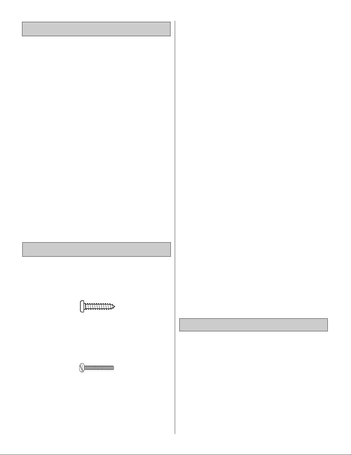
There are two types of screws used in this kit:
Sheet metal screwsare designated by a number and a length.
For example #6 x 3/4" [19mm]
This is a number six screw that is 3/4"
[19mm]
long.
Machine screws are designated by a number , threads per
inch, and a length.
For example 4-40 x 3/4" [19mm]
This is a number four screw that is 3/4"
[19mm]
long with
forty threads per inch
.
·
When you see the term
test fit
in the instructions, it
means that you should first position the part on the
assembly without using any glue, then slightly modify
or
custom fit
the part as necessar y for the best fit.
·
Whenever the term
glue
is written you should rely upon
your experience to decide what type of glue to use.When
a specific type of adhesive works best for that step, the
instructions will make a recommendation.
·
Whenever just
epoxy
is specified you may use
either
30minute (or 45-minute) epoxy or6-minute epoxy. When
30-minute epoxy is specified it is highly recommended
that you use only 30-minute (or 45-minute) epoxy,
because you will need the working time and/or the
additional strength.
·
Photos and sketches are placed before the step they
refer to. Frequently you can study photos in following
steps to get another view of the same parts.
·
The Super Stearman is factory-covered with Top Flite
MonoKote film. Should repairs ever be required,
MonoKote can be patched with additional MonoKote
purchased separately. MonoKote is packaged in six-foot
rolls, but some hobby shops also sell it by the foot. If only
a small piece of MonoKote is needed for a minor patch,
perhaps a fellow modeler would give you some.
MonoKote is applied with a model airplane covering iron,
but in an emergency a regular iron could be used. A roll
of MonoKote includes full instructions for application.
Following are the colors used on this model and order
numbers for six foot rolls.
White TOPQ0204
Black TOPQ0208
True Red TOPQ0227
·
The stabilizer and wing incidences and engine thrust
angles have been factory-built into this model. However,
some technically minded modelers may wish to check
these measurements anyway. To view this information
visit the web site at www.greatplanes.com and click on
“Technical Data.” Due to manufacturing tolerances which
will have little or no effect on the way your model will fly,
please expect slight deviations between your model and
the published values.
1/64" = .4mm
1/32" = .8mm
1/16" = 1.6mm
3/32" = 2.4mm
1/8" = 3.2mm
5/32" = 4mm
3/16" = 4.8mm
1/4" = 6.4mm
3/8" = 9.5mm
1/2" = 12.7mm
5/8" = 15.9mm
3/4" = 19mm
1" = 25.4mm
2" = 50.8mm
3" = 76.2mm
6" = 152.4mm
12" = 304.8mm
15" = 381mm
18" = 457.2mm
21" = 533.4mm
24" = 609.6mm
30" = 762mm
36" = 914.4mm
1" = 25.4mm (conversion factor)
Metric Conversions
Important Building Notes
Optional Supplies and Tools
Page 5
5
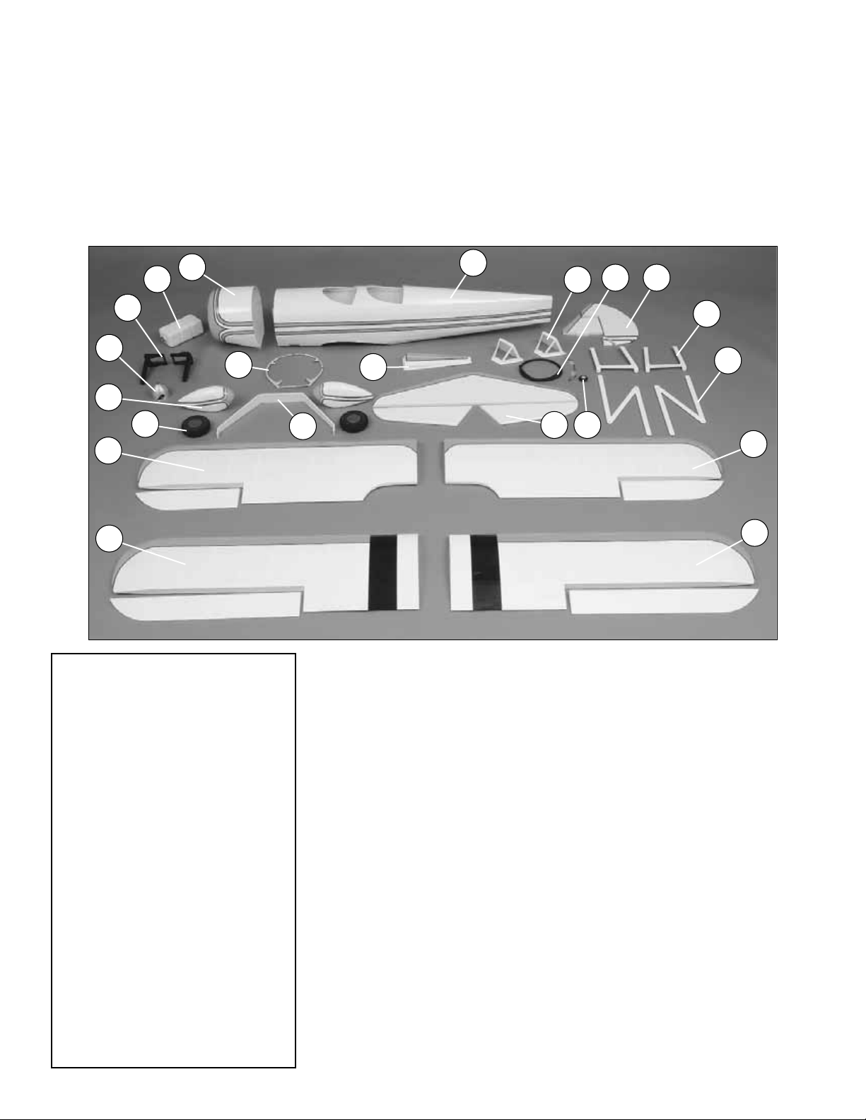
PARTS PHOTOGRAPHED
1. Fuselage
2. Cowl
3. Fin & Rudder
4. Stab & Elevator
5.Top, Left Wing & Aileron
6.Top, Right Wing & Aileron
7. Bottom, Left Wing & Aileron
8. Bottom, Right Wing & Aileron
9. Fuel T ank
10. Engine Mount
11. Spinner
12.Wheel Pants
13. Landing Gear
14. Cowl Ring
15.Wheels
16.Turtle Deck
17.Windshields
18. Cockpit Coaming
19.Tail Wheel Assembly
20. Cabanes
21. Struts
Qty
4-40 Threaded Metal Clevis . . . . . 4
3/16 x 2”Axle . . . . . . . . . . . . . . . . .2
BrassEZConnector . . . . . . . . . . . .1
4-40 Blind Nuts . . . . . . . . . . . . . .20
4-40 Nuts . . . . . . . . . . . . . . . . . . .4
8-32 Blind Nuts . . . . . . . . . . . . . . .9
5/16-24 Axle Nut . . . . . . . . . . . . . .2
1/4-20 Blind Nut . . . . . . . . . . . . . .2
4-40 Nylon Lock Nuts . . . . . . . . . .8
Large Nylon Control Horn . . . . . . .7
Small Nylon Control Horn . . . . . . .4
1/4-20 Nylon Bolt . . . . . . . . . . . . . .2
Nylon Clevis . . . . . . . . . . . . . . . . .7
Nylon Retainer . . . . . . . . . . . . . . .1
2” x 9” Hinge material . . . . . . . . . .1
Faslink . . . . . . . . . . . . . . . . . . . . .7
Clevis Retainer . . . . . . . . . . . . . .11
#4 x 1/2” SMS . . . . . . . . . . . . . . . .4
6-32 x1/4” SHCS . . . . . . . . . . . . . .6
4-40 x 1/8” Set Screw . . . . . . . . . .1
4-40x 1/4”SHCS . . . . . . . . . . . . . .1
#2 x 3/8” SMS . . . . . . . . . . . . . . .28
Qty
8-32 x 3/4” SHCS . . . . . . . . . . . . .5
4-40 x 1/2” SHCS . . . . . . . . . . . .16
4-40 x 1/2” Phillips Head M/S . . . .8
#2 x 3/8” WoodScrew . . . . . . . . . . .8
8-32 x 1-1/4” SHCS . . . . . . . . . . . .4
8-32 x 1”SHCS . . . . . . . . . . . . . . .4
#2 x 1/2” SMS . . . . . . . . . . . . . . . .4
#4 x 1” MS . . . . . . . . . . . . . . . . . .4
3/32” Wheel Collar . . . . . . . . . . . . .1
5/32” Wheel Collar . . . . . . . . . . . . .2
3/16” Wheel Collar . . . . . . . . . . . . .4
1-1/4” Tail Wheel . . . . . . . . . . . . . .1
.074 x 17-1/2”” Pushrod Wire . . . . .1
.074 x 36” Pushrod Wire . . . . . . . .3
.074 x 6” Pushrod Wire . . . . . . . . .4
#4 Lock Washers . . . . . . . . . . . . .16
#4 Flat Washer . . . . . . . . . . . . . .24
#2 FlatWasher . . . . . . . . . . . . . . .10
#8 Lock Washers . . . . . . . . . . . . . .8
#8 FlatWasher . . . . . . . . . . . . . . . .8
4-40 x 3/4” SHCS . . . . . . . . . . . . .4
Parts Layout
Before starting to build, take an inv entory of this kit to make
sure it is complete, and inspect the parts to make sure they
are of acceptable quality. If any parts are missing or are not
of acceptable quality, or if you need assistance with
assembly, contact Product Support. When reporting
defective or missing parts, use the part names exactly as
they are written in the Kit Contents list on this page.
Great Planes Product Support
3002 N Apollo Drive, Suite 1
Champaign, IL 61822
Telephone: (217) 398-8970, ext. 5
Fax: (217) 398-7721
E-mail: airsupport@greatplanes.com
13
15
19
17
9
10
6
20
21
4
5
11
12
1
3
18
2
8
7
14
16
PARTS NOT PHOTOGRAPHED
KIT INSPECTION
Page 6
Replacement parts for the Great Planes Super Stearman ARF
are available using the order numbers in the Replacement
Parts List that follows. The fastest, most economical service
can be provided by your hobby dealer or mail-order company.
Parts may also be ordered directly from Hobby Services, but
full retail prices and shipping and handling charges will apply.
Illinois and Nevada residents will also be charged sales tax.
To locate a hobby dealer, visit the Hobbico web site at
www.hob bico .com.Choose "Where to Buy" at the bottom of the
menu on the left side of the page. Follow the instructions
provided on the page to locate a U.S ., Canadian or International
dealer.If a hobby shop is not available, replacement parts may
also be ordered from Tower Hobbies at www .to werhobbies.com,
or by calling toll free (800) 637-6050, or from Hobby Services by
calling (217) 398-0007, or via facsimile at (217) 398-7721. If
ordering via fax, include a Visa or MasterCard number and
expiration date for payment.
Mail parts orders and payments by personal check to:
Hobby Services
3002 N Apollo Drive, Suite 1
Champaign IL 61822
Be certain to specify the order number exactly as listed in the
Replacement Parts List. Payment by credit card or personal
check only;no C.O.D .
If additional assistance is required for any reason, contact
the appropriate Product Support by e-mail or by telephone
at (217) 398-8970.
productsupport@greatplanes.com
REPLACEMENT PARTS LIST
Order Number Description How to purchase
GPMA2460 . . . . . Bottom Wing Set. . . . . Hobby Supplier
GPMA2461 . . . . . Top Wing Set . . . . . . . Hobby Supplier
GPMA2462 . . . . . Fuselage Kit . . . . . . . . Hobby Supplier
GPMA2463 . . . . . Tail Surface Set . . . . . . Hobby Supplier
GPMA2464 . . . . . Landing Gear . . . . . . . Hobby Supplier
GPMA2465 . . . . . Cowl Set. . . . . . . . . . . Hobby Supplier
GPMA2466 . . . . . Wheel Pant Set. . . . . . Hobby Supplier
GPMA2467 . . . . . Cabane Set. . . . . . . . . Hobby Supplier
GPMA2468 . . . . . Strut Set . . . . . . . . . . . Hobby Supplier
GPMA2469 . . . . . Spinner. . . . . . . . . . . . Hobby Supplier
GPMA2470 . . . . . "Dummy" Radial Eng. . Hobby Supplier
GPMA2471 . . . . . Decal Sheet . . . . . . . . Hobby Supplier
GPMA2472 . . . . . Windscreen Set . . . . . Hobby Supplier
GPMA2473 . . . . . Metal Brackets . . . . . . Hobby Supplier
GPMZ0293 . . . . . Instruction Manual. . . . Hobby Supplier
Missing pieces. . . . . . Product Support
Instruction manual. . . Product Support
Full-size plans. . . . . . . . . Not available
If you have never worked with fiberglass there are a few
basic things you should be aware of.
1. When you are cutting into fiberglass, be sure you are
cutting the correct place.Unlike w ood, you are not ab le to go
back and easily fix a mistake.
2.Whenever you are gluing a part to the inside of fiberglass it
is important to roughen the inside surface of the fiberglass with
220-grit sandpaper, then wipe the area with alcohol. The
molding process leaves a waxy residue that can prevent a
good bond between the glue and the parts being glued.
3. If you do not have a high-speed motor tool such as a
Dremel™tool you should consider purchasing one or
borrowing one from a fellow modeler. This combined with a
fiberglass cut-off wheel is going to be extremely helpful in
the assembly process.
WARNING: The cowl, wheel pants and fuselage included in
this kit are made of fiberglass, the fibers of which may cause
eye, skin and respiratory tract irritation. Never blow into a part
to remove fiberglass dust, as the dust will blow back into your
eyes.Always wear safety goggles, a particle mask and rubber
gloves when grinding, drilling and sanding fiberglass parts.
Vacuum the parts and the work area thoroughly after working
with fiberglass parts.
❏ 1. If you have not done so already, remove the major
parts of the kit from the box and inspect for damage. If any
parts are damaged or missing, contact Product Suppor t at
the address or telephone number listed in the “Kit
Inspection” section on page 5.
❏ 2. Carefully remove the tape and separate the ailerons
from the wing and the elevators from the stab. If necessary,
use a covering iron with a covering sock on high heat to
tighten the covering. Apply pressure over sheeted areas to
thoroughly bond the covering to the wood.
PREPARATIONS
Important Information about
Working with Fiberglass
Ordering Replacement Parts
6
Page 7
Do the right wing first so your work matches the
photos the first time through.You can do one wing at a
time, or work on them together.
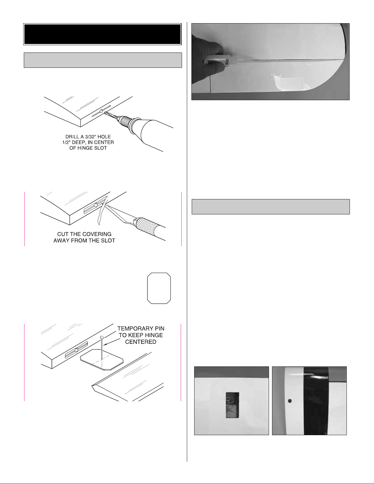
❏❏1. Dr ill a 3/32" [2.4mm] hole, 1/2" [13mm] deep in the
center of each hinge slot to allow the CA to “wick”in. Followup with a #11 blade to clean out the slots.
Hint: If you have one, use a high-speed rotary tool to drill
the holes.
❏❏2.Use a sharp #11 blade to cut a strip of covering from
the hinge slots in the wing and aileron.
❏❏3.Cut fourteen 3/4" x 1" [19 x 25mm]
hinges from the CA hinge strip. Snip off
the corners so they go in easier.
❏❏4. Test fit the ailerons to the wing with the hinges. If
the hinges don’t remain centered, stick a pin through the
middle of the hinge to hold it in position.
❏❏5. Remove any pins you may have inserted into the
hinges. Adjust the aileron so there is a small gap between the
LE of the aileron and the wing. The gap should be small, just
enough to see light through or to slip a piece of paper through.
❏❏6. Apply six drops of thin CA to the top and bottom of
each hinge. Do not use CA accelerator. After the CA has
fully cured, test the hinges by pulling on the aileron.
❏ 7. Repeat steps 1- 6 for the left wing panel.
❏ 8. Follow the same procedure for installing the ailerons
on the top wing panels. Install the ailerons to the top wing
panel with three hinges in each aileron.
Before installing the aileron servos you must make a
decision on whether you will use two or four servos to drive
the four ailerons. A separate servo bay is located in each
wing panel for a four-servo installation. Should you choose
to use the two-servo installation an aileron connecting rod
goes between the top and bottom ailerons. The use of a
connecting rod between the top and bottom wing is “scale”
for a Stearman.If you choose to use the four servos y ou will
not be able to use the aileron connecting rod due to the
differential that is created between the top and bottom
aileron. You will not have any noticeable performance
difference with either option. If you do use two servos you
will need to make sure they are at least 54 oz-in servos.
Using four servos allows you to use less powerful servos
(and most likely less expensiv e servos) b ut the y will need to
be at least 30 oz-in servos.
The following steps are required whether you install two or
four servos.
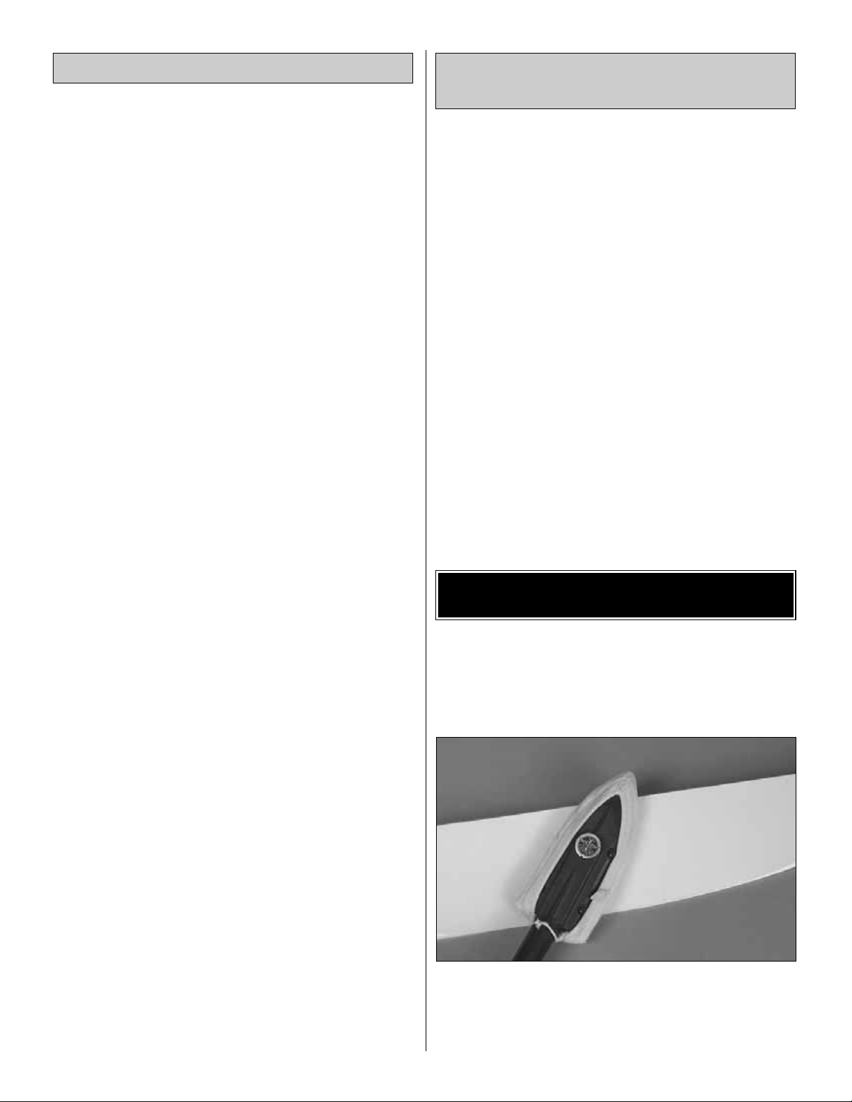
❏❏1.Cut awa y the co vering from the servo bay in the bottom
of the right bottom wing panel.Turn the wing over and cut the
covering from the hole in the top of the wing at the wing root.
Join the Wing
Install the Ailerons
BUILD THE WING
7
Page 8
❏❏2. A string is taped inside the servo bay. Carefully
remove the string from the servo bay and tape it to the
outside of the wing to prevent it from dropping back into the
wing. The other end of the string is taped to the root rib.
Remove the tape, thread the string through the small holes
you cut the covering from on the bottom of the wing and
tape the string to the wing.
❏ 3. Repeat steps 1 and 2 for the left bottom wing.
If you are installing servos in the top wing, proceed with
steps 4 and 5. If not, skip ahead to step 6.
❏❏4. Star ting with the right wing panel for the top wing,
cut away the co v ering from the servo opening on the bottom
of the wing and the covering from the hole at the root of the
wing. Remove the tape from the root rib, thread the string
through the hole and tape the string to the wing. Tape the
string in the servo bay to the wing, too.
❏ 5. Repeat step 4 for the left wing.
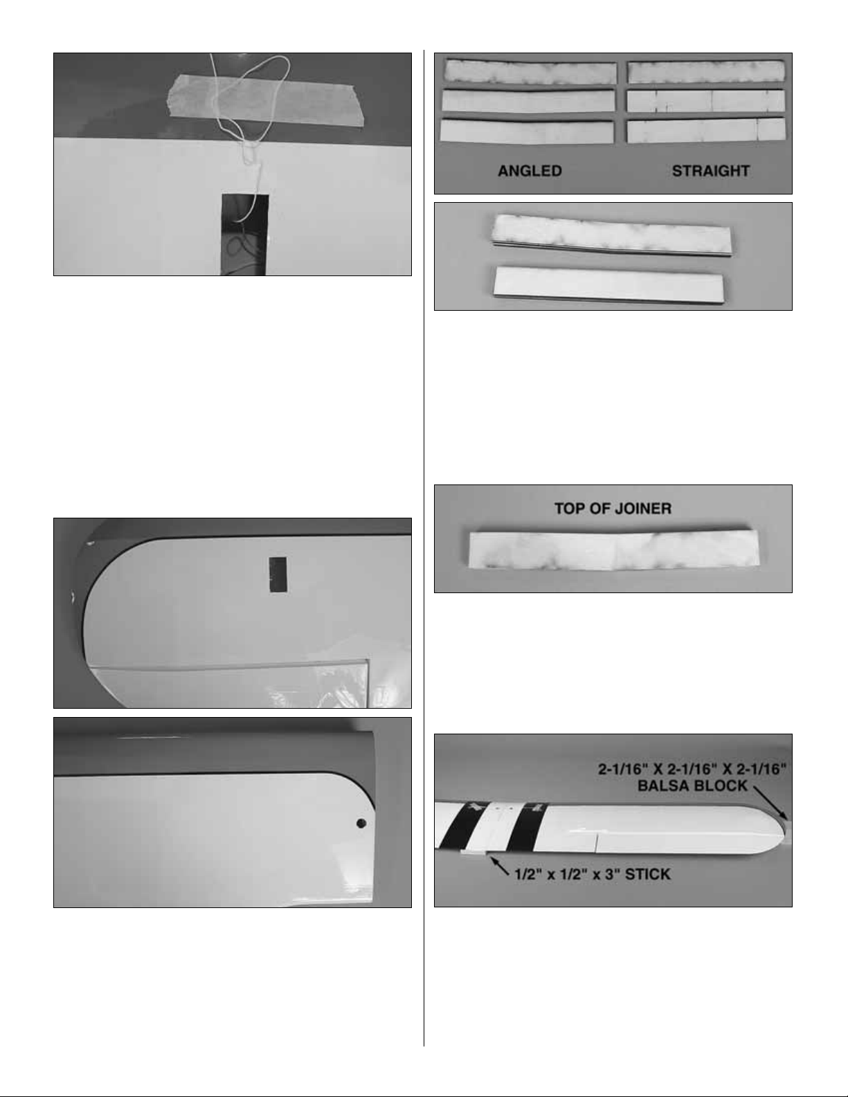
❏ 6. Locate three 1/8" [3mm] straight plywood wing joiners
and three 1/8" [3mm] plywood wing joiners that are angled.
Using 6-minute epoxy, glue the straight ones together to form
one 3/8" [10mm] joiner and glue the three angled ones
together forming the 3/8" [10mm] angled wing joiner.
❏ 7. After the glue has cured, test fit the angled joiner into
the bottom wing panels and the straight joiner into the top
wing panels. Sand the joiners as needed to get a good fit.
❏ 8. When you are satisfied with the fit of the joiners, glue
the angled joiner into the bottom wing panels with
30-minute epoxy. Be sure that the top of the joiner is
towards the top of the wing. When gluing the wing panels
together be sure to get glue into the joiner pockets in the
wing.This can be done by applying the glue into the pocket
with a small stick. Apply glue to the pocket, the joiner and
the root rib of the wing.
Before the glue cures, set one wing half flat on your bench.
Insert the 1/2" x1/2" x 3" [13 x 13 x 75mm] balsa block under
the trailing edge of the wing that sits flat on the workbench.
Block up the wing tip of the other wing half with the 2-1/16" x
2-1/16" x 2-1/16" [52 x 52 x 52mm] balsa block included in the
kit. Put small weights on the wing half that is flat on the bench
to keep it lying flat and leave the b loc k under the wing tip of the
other wing half while the glue cures.
8
Page 9
❏ 9. Hold the wing together with masking tape while the
glue is curing. Excess epoxy can be cleaned away with
denatured alcohol and a paper towel.
❏ 10. Glue the top wing together using the straight wing
joiner and following the same gluing procedure used on the
bottom wing. Note: There is no dihedral on the top wing.
After gluing the wing together be sure it remains flat on the
workbench while the glue cures.
❏❏1.On the lower wing, install a 12" [305mm] servo extension
onto the servo lead.Secure the extension to the lead with tape, a
piece of shrink tube or some other method to keep them from
coming unplugged.
❏❏2. Tie the string to the servo extension. At the root of
the wing the other end of the string is taped. Pull the str ing
and the servo lead through the wing. Untie the string from
the lead and insert the lead through the small hole you cut
the covering from. Tape the lead to the wing to prevent it
from falling back into the wing.
❏❏3. Install the servo into the servo opening.Drill through
the servo mounting holes with a 1/16" [1.6mm] drill bit.
Remove the servo from the servo opening. Install and then
remove a servo mounting screw into each of the holes you
have drilled.Apply a drop of thin CA into the holes to harden
the threads. Once the glue has cured install the ser vo into
the servo opening using the hardware included with your
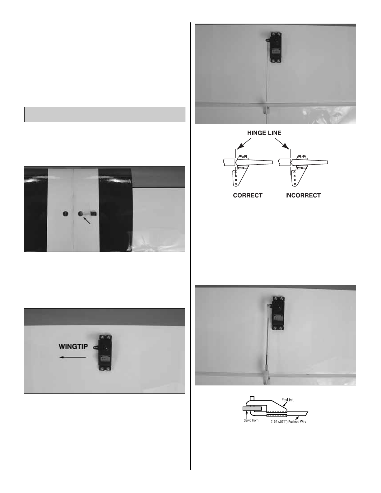
servo.Center the servo, then install a servo arm as shown.
The arm should be pointing towards the wingtip.
❏❏4. Place a nylon clevis in line with the last hole in the
servo arm. When positioned properly the control horn will
rest on a hardwood plate in the aileron.Mark the location of
the mounting holes onto the aileron. Drill a 1/16" [1.6mm]
hole on the marks, drilling through the plywood plate
b
ut not
through the top of the aileron. Insert and remove a #2 x3/8"
[10mm] screw into each of the holes. Apply a couple drops
of thin CA into the holes to harden the threads. Once the
glue has cured attach the horn to the aileron with two #2 x
3/8" [10mm] screws.
❏❏5. Thread a nylon clevis onto a .074 x 6" [152mm]
threaded wire 20 turns. Slide a silicone clevis retainer onto
the clevis. Install the clevis into the second hole from the
end of the control horn, then slide the silicone retainer over
Install the Aileron Servos & Pushrods
9
Page 10
the clevis. Drill a 5/64" [2mm] hole in the outer hole of the
servo arm. Center the servo and the aileron.With a fine-tip
marker, mark the wire where it aligns with the outer hole of
the servo arm. Make a 90 degree bend on the mark.Cut the
wire so the wire is 3/8" [10mm] in length after the bend.
Insert the wire into the ser vo arm and lock it in place with a
nylon Faslink.
❏6. Repeat steps 1-5 for the left wing panel.
If you are installing servos in the top wing, repeat steps
1-6 for the top wing. If not, skip ahead to Step 12. St
eps
7- 11 are only if you are installing servos in the top wing.
❏7. A “Y” harness is required to connect the servos in the
upper wing to the receiver. Plug the two servo leads in the
top wing into a “Y” harness compatible with your radio
system.To provide a plug into the receiver we have used a
slightly modified Ernst Charge Receptacle (ERN3124 for
Futaba) and a 12" [305mm] servo extension.
❏ 8. Cut the charge receptacle in half just above the
locking fingers.
❏9. Put a couple of small drops of medium CA on the sides
of the female end of the servo extension. Then slide the
servo extension into the charge receptacle.
❏ 10. Near one of the cabanes, cut a hole in the top of the
fuselage just large enough for the servo extension and the
charge receptacle to fit into. Drill a 1/16" [16mm] hole into the
fuselage through each of the mounting holes in the charge
receptacle. Thread and remove the screws from the charge
receptacle into the holes you drilled. Apply thin CA into the
holes to harden the threads.Glue the charge receptacle to the
fuselage with R/C 56 canopy glue.Install the mounting screws
in the charge receptacle, into the holes you have drilled.
Later, when you are installing the radio system, this servo
extension will be plugged into the proper channel of your
receiver.When preparing the airplane to fly you will be able to
plug the upper wing servos into the receptacle, completing the
the connection from the upper wing to the receiver.
❏ 11. On the bottom wing, cut the covering away from the
holes in the leading edge of the wing for the nylon wing
dowels. Glue them in place with 6-minute epoxy. Wipe any
excess epoxy away with denatured alcohol. When properly
positioned the wing dowels should extend approximately
3/8" [10mm] beyond the leading edge of the wing.
❏ 12. Cut the covering from the holes on the plywood wing
bolt plate.
❏ 13. Cut the covering from the holes at the wing trailing
edge on both the top and bottom of the wing.
10
Page 11
❏14. Place the wing bolt plate in position over the holes in the
bottom wing. Use the nylon wing bolts to help you align the
holes in the plate with the holes in the wing.T race the outline of
the plate onto the covering with a felt-tip pen. Use a sharp #11
blade or the expert tip that follows to cut the co vering inside the
lines you have drawn. Use caution not to cut through the
surface of the wing skin.Remove the covering.
❏ 15.Glue the wing bolt plate to the wing using epoxy. Use
small clamps to hold the wing bolt plate in position while the
glue cures.
❏ 1. Remove the belly pan from the bottom of the fuselage.
Install the landing gear to the fuselage with five 8-32 x 3/4"
[19mm] socket head cap screws. Apply a drop of thread
locker to each bolt before installing them.
❏ 2. Glue the belly pan back in place with a few dabs of
silicone glue. Using silicone will allow you to remove the
belly pan easily should you ever have to get access to the
landing gear bolts.
We will come back and do the installation of the wheels and
wheel pants later.Having the landing gear installed at this time
will make it easier to handle the fuselage on the workbench.
❏ 3. Cut the covering from the fuselage where the
horizontal stabilizer fits into the fuselage.
❏ 4. Cut the covering and the wood block from the back of
the horizontal stabilizer saddle.
Preparations
BUILD THE FUSELAGE
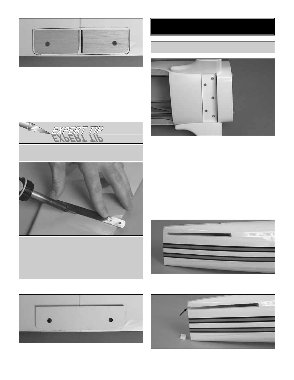
Use a soldering iron to cut the covering. The tip of the
soldering iron doesn't have to be sharp, but a fine tip does
work best. Allow the iron to heat fully. Use a straightedge
to guide the soldering iron at a rate that will just melt the
covering and not burn into the wood. The hotter the
soldering iron, the faster it must travel to melt a fine cut.
Peel off the cover ing.
HOW TO CUT COVERING FROM BALSA.
11
Page 12
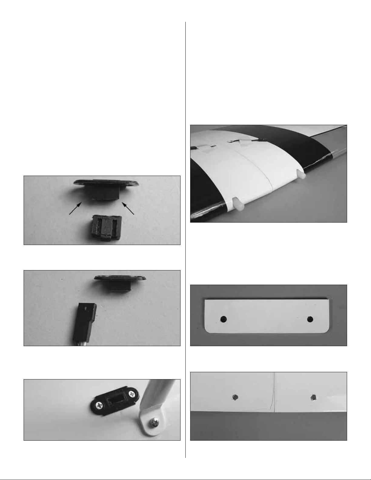
❏1.Temporarily attach the lower wing to the fuselage with the
1/4-20 nylon bolts. Slide the horizontal stabilizer into the slot
in the fuselage. Stand back and look at the stab in relation to
the wing.The stab should be parallel with the wing. If not, sand
the stab saddle until the stab and wing are aligned.
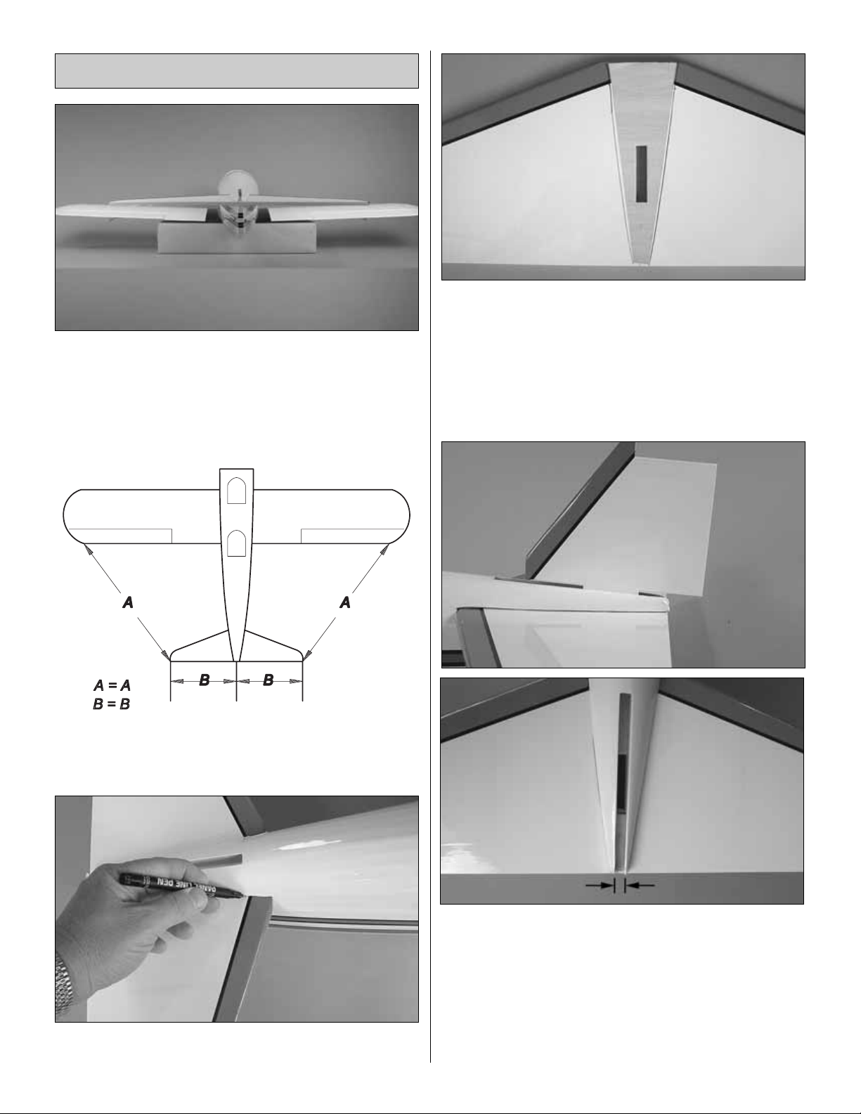
❏2. Measure the distance from the tip of the stab to the tip of
each wing. Adjust the position of the stab until they are equal.
❏3. Using a felt-tip pen, mark the outline of the fuselage on
the top and the bottom of the stab.
❏ 4. Cut the covering on the top and bottom of the stab
inside the line you have drawn. Use the same technique for
removing the covering from the wing.
❏5.Glue the stab in place with 30-minute epoxy .Excess epoxy
can be cleaned away with a paper towel and denatured
alcohol. After the stab is positioned and all excess epoxy has
been cleaned away, temporarily install the vertical fin par t of
the way into the slot.Just put it into place enough to verify that
you have not pushed the wood fuselage fairings too close
together and that the slot in the stab is aligned with the opening
for the fin. Remove the fin and allow the glue to cure.If any glue
has gotten on the fin, remove it with denatured alcohol.
Install the Stab, Elevator, Fin & Rudder
12
Page 13

❏ 6. Remove the bottom wing from the fuselage.
Temporarily install the fin into the slot in the top of the
fuselage. Using a fine-point felt-tip pen, mark the outline of
the fuselage onto the fin. Cut the covering from the fin using
the same method used earlier.
❏ 7. Test fit the fin into the fuselage. Check to be sure the
fin is perpendicular to the stab. If it is not, sand the side of
the fin to make minor adjustments. Once you are satisfied
with the fit, glue the fin to the fuselage with epoxy.
❏ 8. Using the same installation method used previously,
install three hinges into each elevator half. Then install the
elevators into the stab. Glue the hinges using thin CA.
Did you know?
...Built as a private venture by the
Stearman Aircraft Company of Wichita (bought by Boeing in
1934), this two-seat biplane was of mixed construction.The
wings were of wood with fabric covering while the fuselage
had a tough, welded steel framework, also fabric cov ered.In
1936, the Army tentatively bought 26 airframes from Boeing
(the Model 75), which the Army named the PT-13. With war
on the horizon, this trickle of acquisition soon turned into a
torrent; 3519 were delivered in 1940 alone.
Did you know?
...The Stearman gained a reputation as
a rugged airplane and a good teacher. Officially named the
Boeing Model 75, the plane was (and still is) persistently
known as the “Stearman” by many who flew them. It was
called the “PT”by the Army, “N2S” by the Navy and “Kaydet”
by Canadian forces. By whatever name, more than 10,000
were built by the end of 1945 and at least 1,000 are still
flying today worldwide.
❏9.Locate the tail wheel wire.Test fit it into the two slots in the
back of the fuselage.Use your hobby knife to clean out the slots
if it is too tight. Once satisfied with the fit, remove the wire from
the slots. Apply a couple of drops of oil to the wire where it
passes through the nylon bearings.This will prevent glue from
getting onto the wire. Apply epoxy to the nylon tabs and then
install the tail wheel wire into the fuselage.
13
Page 14

❏10. Cut the covering from the front of the balsa triangle tail
block.Cut the covering from the back of the fuselage where the
block will be glued to the fuselage.Test fit the block over the
landing gear wire.Make adjustments to the slot in the block as
needed. Glue the block to the fuselage. Be careful not to get
glue on the wire.
❏ 11. Cut the covering from the hole on the leading edge,
bottom of the rudder.Test fit the hinges into the rudder and
then fit the rudder to the fin and fuselage. Make any
adjustments that may be needed to the slot in the rudder.
When you are satisfied everything fits well, put a small
amount of epoxy into the hole in the rudder, install the
hinges in the rudder and install the rudder to the fin.
❏ 12. Glue the hinges to the fin and rudder with thin CA.
Did you know?
...After World War II, many Stear mans
were fitted with Pratt & Whitne y 450 h.p .engines and utilized
as crop dusters. These more powerful Stearmans are also
commonly known as the “Super Stearman” and used for
wing-walking or aerobatic routines at air shows.
❏ 1. Attach the lower wing to the fuselage with the 1/4-20
nylon bolts.
❏❏2. Locate eight metal cabane mounting brackets. The
photograph identifies the correct brack et f or the top and bottom
wing. Set the four brackets for the top wing to the side. We will
be installing the brackets on the bottom wing first.
Do the right wing first so your work matc hes the photos
the first time through.
Attach the Wing and Cabanes
14
Page 15

❏❏3. Look closely on the top of the bottom wing and you
will find a small pin hole locating the blind nuts for the
cabane mounting bolts. Cut the covering from each of the
holes.
Note: 4-40 blind nuts have been installed in the wing
for all of the cabane mounting bolts.All of the blind nuts are
glued into the wing and have a small wood plate backing
them up.It is possible that a blind nut could have a bit of glue
in the threads. In most cases the installation of the bolt
should free the glue. If not, run a 4-40 tap through the
threads to clear the glue.
❏❏4. Mount the bottom wing cabane brackets in each of
the holes in the right wing panel with a 4-40 x 1/2" [13mm]
socket head cap screw and a #4 lock washer. Do not fully
tighten the bracket to the wing yet.
❏❏5. Position the “N” strut to the bracket. Located on the
strut is a piece of masking tape with an arrow that indicates
the top, front of the strut.
❏❏6. Attach the strut to the bracket as shown with a 4-40
x 1/2" [13mm] phillips head screw, a #4 washer and a 4-40
nylon lock nut.
❏ 7. If you have not been doing the bracket installation on
both the right and left wing, go back and repeat steps 3-6 for
the left wing panel.
15
Page 16

❏ 8. Locate the pin holes and cut the covering from the blind
nuts in the bottom of the top wing.Four are located in the center
of the wing and two are located at each end of the wing.
❏ 9. Install the center cabanes with 4-40 x 1/2" [13mm]
socket head cap screws and #4 lock washers. Be sure you
mount the cabanes as shown.
❏ 10. Install the four remaining brackets in the blind nuts at
the ends of the wing.
❏ 11. Place the top wing onto the “N” struts. Attach the top
wing to the “N” str uts with 4-40 x 1/2" [13mm] phillips head
screws, #4 washers and 4-40 nylon lock nuts the same way
you installed the strut to the lower brackets.
❏12. Set the fuselage on the firewall.Look at the relation of
the top wing to the bottom wing. Be sure the top wing is
parallel with bottom wing. Adjust the top wing as needed.
Then carefully set the fuselage back on the landing gear.
❏ 13. Without disturbing the top wing, push a T-pin into the
fuselage through each of the cabane mounting holes.Push the
pin hard to verify that the mounting holes are positioned over
the hardwood rails. If you do not find hardwood and only hit
balsa wood, check to see if you have mounted the center
cabanes properly. If you have the center cabanes backwards
they will not align over the hardwood rails.
❏ 14. Drill a 5/64" [2mm] hole through each of the four
mounting holes in the center cabanes.When you drill these
holes you must be drilling into the hardwood rails located in
the fuselage.
❏15. Install and then remove a #4 x 1/2" sheet metal screw
into each of the four holes.Apply a couple drops of thin CA
into each of the holes to harden the threads. After the glue
has cured permanently install the screws into the fuselage.
16
Page 17

If you have decided to install four servos in the wings
instead of two, skip the 12 steps in this section and proceed
to, “Build the Carry Handle”.
❏❏1. Locate two small nylon control horns. Cut them
as shown.
❏❏2. On the bottom wing, on top of the aileron is a large
plywood plate. Outline this plate with a felt-tip marker (this
can be wiped away later with denatured alcohol) or outline it
with masking tape.
❏❏3. On the top wing, on the bottom of the aileron is a
large plywood plate. Outline this plate with a felt-tip marker
(this can be wiped away later with denatured alcohol) or
outline it with masking tape.
❏❏4.Measure from the inside edge of the plate out 1-1/2"
[38mm] and draw a line. Measure from the trailing edge of
the aileron in 1-3/8" [35mm] and draw another line.
❏❏5.Position one of the cut control horns so the holes in the
control horn are positioned over the intersection of the two lines
you have dr awn.Note that the holes face the trailing edge of the
aileron. Mar k the hole locations and drill a 1/16" [1.6mm] hole
through each of the marks. Be sure to drill only through the
plywood plate. Insert and remove a #2 x 3/8" [10mm] sheet
metal screw into each of the holes.Apply a couple of drops of
thin CA into the holes to harden the threads. After the glue
cures, mount the control horn with the screws.
Install the Aileron Connecting Rod
17
Page 18

❏❏6. Locate the aileron connecting rod. Cut the excess
rubber coating to expose all of the threads.
❏❏7. Install a 4-40 nut, 4-40 metal clevis and a silicone
clevis keeper on both ends of the connecting rod.
❏❏8. Install one end of the connecting rod to the outer
hole of the control horn on the aileron of the top wing.
❏❏9.Attach the remaining control horn to the other end of
the connecting rod. Adjust the clevises so that the length of
the connecting rod allows the top aileron and bottom
ailerons to be neutral.
Place the control horn on the aileron of the bottom wing.
position it as needed until the connecting rod is aligned with the
back of the “N”strut and parallel to the “N” strut as viewed from
the side. Once properly positioned, mark the location of the
clevis holes. This will make the center of the clevis holes
approximately 1" [25mm] from the trailing edge of the aileron.
❏❏10. Drill a 1/16" [1.6mm] hole through each of the
marks.Be sure to drill only through the plywood plate.Insert
and remove a #2 x 3/8" [10mm] sheet metal screw into each
of the holes. Apply a couple of drops of thin CA into the
holes to harden the threads. After the glue cures mount the
control horn with the screws.
❏❏11.Make any additional adjustments to the clevises on
the ends of the connecting rod as needed until both the top
and bottom aileron are neutral. Tighten the 4-40 nuts
against the clevises on the connecting rod to prevent the
connecting rod from rotating.
❏ 12. Repeat steps 1-11 for the left wing.
18
Page 19

This kit comes with a convenient carrying handle for the
fuselage and the struts.It is also useful during the remainder
of the construction process because, when installed, it will
allow you to turn the plane upside-down on the workbench
without flexing or bending the center cabanes.
❏1. Locate all of the 1/8" [3mm] plywood parts of the handle.
❏ 2. Glue the three par ts of each set together as shown to
make a pair 3/8" [9mm] thick.
❏ 3. Do the same with the remaining six par ts, making two
pairs of each.
❏ 4. Glue the two parts shown onto one of the plywood
handle parts.
❏ 5. Place the “N” struts onto the handle leaving space
between the struts in the center of the handle as shown. The
remaining parts you glued together should be fit between the
“N” struts. Once you are sure the struts and the remaining
pieces fit properly, glue the plywood parts to the handle.
❏ 6. On the remaining handle part, install a 4-40 blind nut
into each of the corner holes.
Build the Carry Handle
19
Page 20

❏ 7. Place the two “N” str uts into the handle and the two
aileron connecting rods between the struts. Put the handle
top onto the part of the handle holding the struts and place
the completed handle on top of the cabanes. Secure the
handle to the cabanes with four 4-40 x 3/4" [19mm] socket
head cap screws and #4 flat washers. This is how the
completed handle looks when you are storing the parts or
taking the plane to the field.
❏ 8. For the following building steps it will be better to
remove everything from the handle. Do this now and secure
the empty handle to the cabanes.
Did you know?
...The primary differences between the
“Super Stearman” and the original war time Stearmans are
the larger 450 horsepower Pratt and Whitney engine,
additional flying and landing wires, the installation of two
additional ailerons on the top wing, cowl and wheel pants!
❏ 1. Cut the tabs from the engine mount. Install the engine
mount (inverted) to the firewall with four 8-32 x 1-1/4" [32mm]
socket head cap screws, #8 flat washers and #8 lock washers.
❏ 2. Position the engine on the mount so the distance from
the firewall to the front of the thrust washer measures 6-1/4"
[159mm]. Mark the location of the engine on the mount.The
Great Planes®Dead Center™Hole Locator (GPMR8130)
works well for this. Drill through the mar ks you have made
on the engine mount with a #29 or 9/64" [3.6mm] drill bit.Tap
each of the holes with an 8-32 tap.
❏ 3. Install the engine onto the mount with four each, 8-32
x 1" [25mm] socket head cap screws, #8 flat washers and
# 8 lock washers.
Install the Engine & Throttle Servo
20
Page 21

❏ 4. Drill a 3/16" [4.8mm] hole through the firewall in line
with the throttle arm on the carburetor.
❏ 5.Locate the 24" [610mm] gray plastic pushrod tube and
cut it 12-3/4" [324mm] in length. Sand one end of the tube
with 220-grit sandpaper. Insert the tube into the firewall.
Glue the roughened end of the tube flush to the firewall.
❏ 6. Place your throttle servo into the servo tray as shown.
Drill a 1/16" [1.6mm] hole through each of the mounting
holes. Remove the servo. Then install and remove a servo
mounting screw into each hole.Apply a couple drops of thin
CA into the holes to harden the threads.When the glue has
cured permanently, mount the servo to the servo tray.
❏ 7. Cut the 1" [25mm] threaded end from the .074" x
17-1/2" [445mm] throttle pushrod wire. Install the wire into
the tube and attach it to the servo horn arm with a Faslink.
Use the same technique used for the ailerons.
❏8. Attach the pushrod wire to the throttle arm with a brass
screw-lock connector, nylon retainer ring and a 4-40 x 1/4"
[6mm] socket head cap screw.
21
Page 22

❏ 1. Locate the plywood cowl ring and the four cowl ring
mounting tabs. Note that the cowl ring has blind nuts pre-
installed in one side.
❏2. Screw the cowl mounting tabs to the cowl ring with four
4-40 x 1/2" [13mm] socket head cap screw and flat w ashers.
Position the tabs as shown.
❏3.Position the co wl ring and the tabs on the ref erence marks
on the front of the firewall.When properly positioned the top of
the cowl ring should be flush with the top of the fuselage and the
sides should be positioned equally from the sides of the
fuselage.When positioning the cowl ring be sure that the blind
nuts on the cowl ring face forward and the heads of the screws
face rearward.Apply CA to the back of the tabs, place the cowl
ring and tabs in position on the firewall and hold it in position on
the firewall until the glue has cured.
❏ 4. Using a 1/16" [1.6mm] drill bit, drill through each of the
four mounting tabs and the firewall. Thread a #2 x 3/8"
[9mm] wood screw into each of the holes.
❏ 5. Slide the cowl onto the front of the fuselage.You will
probably not be able to slide the cowl into position
completely due to the engine making contact with the
bottom of the cowl. Slide the cowl on as far as you can,
Install the Cowl & Dummy Engine
22
Page 23

centering it as much as possible. At the point where the
engine begins to make contact with the cowl, mark the
inside of the cowl with a felt-tip marker. Make small cut outs
in the cowl where the engine contacts the fuselage until you
can completely slide the cowl into position. Install the back
plate of the spinner and the propeller onto the engine
crankshaft. This will help you position the cowl. When
centering the cowl, be sure to match the stripes on the side
of the cowl with the stripes on the side of the fuselage.
❏ 6. Once you are satisfied with the position of the cowl,
tack glue the cowl ring to the cowl with medium CA using a
CA applicator tip.Apply the glue on the back of the co wl ring
and apply some CA accelerator to the glue to enable it to
cure quickly. Do this on both sides of the cowl.
❏ 7. Remove the four screws from the cowl ring, and then
remove the cowl from the fuselage.
❏ 8. Sand the inside of the cowl, in front of the cowl ring with
220-grit sandpaper.Wipe the area clean with denatured alcohol
and allow the area to dry .Mix one ounce of 6-minute epoxy and
micro balloons.Apply a fillet of the glue to the cowl and the cowl
ring. Set the cowl aside until the glue has cured.
❏ 9. Cut out any areas in the cowl that will be required for
the engine cylinder head, muffler, needle v alv e , remote glow
driver, etc.for your particular engine installation.
Note
: When positioning your muffler, angle it away from the
fiberglass landing gear or plan on using an exhaust diverter.
The heat from the muffler will discolor and possibly burn the
surface of the gear.
After all areas have been removed, reinstall the cowl one final time to be sure you are happy with
the installation.
❏ 10. Mix 1/4 ounce of 6-minute epoxy with a few drops of
denatured alcohol to thin the epoxy. Brush a coat of the
mixture on the tabs and the cowl ring to fuelproof the bare
wood.Allow the epo xy to fully cure bef ore attaching the cowl
to the fuselage. You may wish to rub some talcum powder
onto the tabs where they contact the cowl ring to prev ent the
glue from sticking.
❏11. Cut out the center of the dummy engine.Slide it over
the engine crankshaft. Mark the area where the dummy
engine covers the cylinder head of your engine .Remove the
dummy engine and cut out the area you marked.
Note:When installing the dummy engine, one cylinder head
should be at the top of the cowl.Trim the dummy engine as
needed to get it to fit completely forward into the cowl.
❏12.Drill 1/8" [3mm] holes in each of the rocker covers and
the center of the engine for the aluminum pushrod tubes. If
you would like to add some additional detail you may wish
to use wire (not included) as a spark plug lead. We used a
20-gauge red wire, then drilled 1/16" [1.6mm] holes in each
cylinder for the wire.
23
Page 24

24
❏13. Paint the engine flat black. After the paint dries install
the aluminum tubes and wire into the holes you drilled. On
the back of the engine apply a small amount of glue to each
wire and aluminum tube to hold them in place.
❏ 14. Place the dummy engine over the engine, and then
place the cowl over the dummy engine. Attach the cowl to
the fuselage with the four socket head cap screws and
washers.To position the dummy engine you will need two 9"
[229mm] balsa sticks and two small rubber bands (not
included). Loop a rubber band through a couple of the
aluminum tubes on one side of engine crankshaft.Insert the
stick through the rubber bands and place the stick onto the
front of the cowl. This will pull the dummy engine into the
front of the cowl. Repeat this with the second stick and
rubber band on the other side of the engine crankshaft.
❏15.P osition the dummy engine so that the cut out is o ver the
engine cylinder and the hole you cut in the center of the dummy
engine is centered on the engine thrust washer. Be sure the
center cylinder on the dummy engine is centered at the top of
the fuselage.When you are satisfied with the positioning of the
dummy engine, carefully remove the cowl from the fuselage,
being careful not to disturb the dummy engine.
❏ 16. Using medium CA, tack-glue the dummy engine to the
cowl from inside the cowl.Re-install the cowl to the fuselage to
verify that the dummy engine is placed properly. When you are
satisfied with the way it fits, remove the cowl from the fuselage.
Permanently glue the dummy engine to the cowl from inside the
cowl with 6-minute epoxy mixed with microballoons.
❏1. Assemble the fuel tank as shown in the sketch.When
tightening the center screw be sure not to over tighten it.You
just want it snug enough to pull the rubber stopper tight
against the tank.
❏ 2. Install the tank into the fuselage with the neck of the
tank through the firewall.The tank should fit snug enough to
stay in place during the construction process. The tank will
be permanently held in place when the battery/receiver tray
is installed later.
❏ 3. Install silicone fuel tubing onto the aluminum tubes
from the fuel tank.The line with the fuel clunk will feed to the
fuel inlet at the needle valve and the other will attach to the
pressure tap on the muffler.If you choose to use some kind
of an external fuel valve, follow the instructions with your
particular brand of fuel valve.You can also install a third line
to the tank and use it for filling the tank.The method you use
is your choice.
Install the Fuel Tank
Page 25

Our prototype model required the addition of nose weight.
This is not uncommon for short-coupled airplanes such as
the Stearman. We have included a location for you to easily
add the weight that most likely will be needed.
❏1. Locate the plywood parts that make up the box.Glue the
box together as shown. The box will be exposed to engine
vibration so be sure you have good glue joints.
❏2. Glue the two 1/8" x 1/4" x 3-1/4" [3 x 6 x 83mm] plywood
sticks together.Then glue them to the front of the box.
❏ 3. Fit the box cover to the box. Drill a 1/16" [1.6mm] hole
at the locations shown. Install and then remove a #2 x 3/8"
[10mm] sheet metal screw into each hole. Remove the
cover, and then apply a couple of drops of thin CA into the
holes in the box to harden the threads.
❏4.Refering to the photo on the following page, locate two 1/2"
x 11/16" x 2-1/2" [13 x 18 x 64mm] hardwood blocks. Position
one of the blocks on the bottom of the engine mount.The block
should be resting against the engine mount rail and the socket
head cap screw that holds the engine mount to the firewall.You
will see that the block cannot sit on the rail because one of the
engine mount bolts is extending through the rail. Mark the
location of this screw on the block.Where you have marked the
block, cut aw a y enough of the wood to provide clear ance for the
screw, allowing the block to rest against the rail. Repeat this for
the remaining block.
Assemble Nose Weight Box
25
Page 26

❏5.Glue the blocks to the engine mount rails with CA.Drill two
3/32" [2.5mm] holes through each of the blocks and the engine
mount. Drill a 1/8" [3mm] clearance hole through the block
only! Do not drill into the engine mount with the 1/8" [3mm] bit!
Countersink the top of each of the holes you have drilled so that
the screw heads will sit flush with the top of the hardwood
blocks.Install a #4 x 1" [25mm] screw into each of the four holes
making sure that the head of the screw is flush or slightly below
the top of the wood block.
6. Place the box on top of the rails and between the triangle
stock located on the firewall. Drill four 1/16" [1.6mm] holes
through the inside of the box and into the hardwood rails.
Install and then remove a #2 x 3/8" [9mm] wood screw into
each of the holes.Remove the box.Apply a couple of drops
of thin CA into each of the holes to harden the threads.Allow
the glue to cure.
❏ 7. Attach the box to the hardwood blocks. Secure the top
of the box with two #2 x 3/8" [10mm] screws and a two
#2 washers. Fuelproof the box and rails.
That’s it f or no w for our box for lead.When y ou get the plane
ready for flight you will install the appropriate amount of
ballast to balance the plane.
Did you know?
Over the years the Stearman has seen
duty as a primary trainer, a reconnaissance plane, a crop
duster, and an air show perf ormer . In 1934 Argentina, Brazil
and the Philippines used Stearmans featuring wingmounted .30 caliber machine guns, a bomb rack between
the landing struts and a single machine gun for the rear!
❏ 1. Install the tail wheel onto the tail wheel wire, securing it
with a 3/32" [2.4mm] wheel collar and a 4-40 set screw.
❏❏2.You are going to be doing a left and right wheel pant.
Be sure you do not make two wheel pants for the same side.
Do the right side wheel pant first so that your pant matches the
pictures. Place a piece of masking tape on the left side of the
wheel pant. Make a mark at the center of the wheel opening.
Measure up 1/2" [13mm], then make a crossing mark. On this
mark make a 1/2" [13mm] diameter hole, using progressively
larger drill bits or a rotary tool with a cutting burr.
❏❏3. Sand the inside of the wheel pant on the side with
the hole.Wipe the area clean with denatured alcohol. Mix a
Install the Wheels & Wheel Pants
26
Page 27

1/4 ounce [2cc] of 6-minute epoxy and a small amount of
microballoon filler. Locate one of the plywood wheel pant
plates and glue it inside the pant, aligning the hole in the
plate with the hole you made in the side of the pant. Clamp
the plate to the pant and allow the glue to fully cure.
❏❏4. Install the axle and axle nut onto both sides of the
landing gear.Slide onto the right axle: the wheel pant, 3/16"
[5mm] wheel collar and 6-32 x 1/4" [6mm] socket head cap
screw followed by the wheel and another wheel collar and
socket head cap screw. Slide the other wheel onto the left
axle. Both wheels must be on the axles to assure accuracy
of the measurement of the wheel pant in the next step.
❏❏5. Adjust the wheel pant until the center of the trailing
edge of the wheel pant measures 2-1/8" [54mm] from
the workbench.
❏❏6. Holding the wheel pant in that position, drill a 1/16"
[1.6mm] hole through each of the mounting holes in the landing
gear and into the wheel pant. Secure the pant to the landing
gear with two #2 x 1/2" [13mm] screws and #2 washers.
❏❏7. Center the wheel in the wheel pant with the two
wheel collars.Hold the collars in place with the screws .Mark
the location where the screw contacts the axle.Remove the
wheel pants, wheel and wheel collars from the axle.Apply a
couple of drops of thin CA into the two holes you drilled in
the wheel pant.
❏❏8. File a flat spot on the axle on the mark you made.
Re-install the wheel pant, wheel and wheel collars onto the
axle.Center the wheel and tighten the screws against the axle.
❏9. Repeat steps 1-8 for the left wheel pant.
27
Page 28

❏1.Cut the covering from the pushrod tube openings at the
rear of the fuselage.There are two located on the right side
and one located on the left. If you have trouble finding the
openings, slide a .074" x 36" [1.9 x 915mm] pushrod wire
into the tubes from inside of the fuselage, sliding it into the
tube until it pushes the covering away from the fuselage
slightly.This is where you should cut the cov ering aw a y from
the tubes.
❏2. Locate three .074" x 36" [1.9 x 915mm] pushrod wires
threaded on one end. Thread a nylon clevis onto the
threaded end of each wire 20 full turns. Install a silicone
clevis keeper onto the clevis.
❏3. On the right side of the fuselage, slide one wire into the
opening closest to the back of the fuselage. Install a nylon
control horn onto the clevis.Position the control horn on the
rudder, positioning it the same wa y y ou did with the ailerons.
Mark the location for the screw holes. Drill through the
marks you made with a 1/16" [1.6mm] drill bit, drilling only
into the plywood plate. Do not drill through the rudder!
Install and then remove two 2-56 x 5/8" [16mm] machine
screws.Apply a couple drops of thin CA into the holes. Once
the glue has cured, mount the horn and the nylon mounting
plate to the rudder with the screws.
❏ 4. Install the two elevator pushrods using the same
procedure used for the rudder. Be sure when installing the
control horn on the right elevator that you install it so it does
not conflict with the rudder control horn.
❏ 5. Place your rudder ser vo into the servo tray as shown,
positioning the last hole of the servo arm over the pushrod
wire. Drill a 1/16" [1.6mm] hole through each of the
mounting holes. Remove the servo, then install and remove
a servo mounting screw into each hole. Apply a couple
drops of thin CA into the holes to harden the threads.When
the glue has cured, permanently mount the servo to the
servo tray.
❏6. Center the rudder and the rudder servo , then install the
servo arm. At the point the pushrod wire intersects the last
hole in the servo arm make a mark. Bend the wire 90
degrees on that mark. Install a nylon Faslink and cut off the
excess wire the same as was done with the throttle servo.
❏ 7. Place your elevator servo into the servo tray as shown,
positioning the last hole of the servo arm over the inside
pushrod wire. Drill a 1/16" [1.6mm] hole through each of the
mounting holes. Remove the servo, then install and remove a
servo mounting screw into each hole. Apply a couple drops of
thin CA into the holes to harden the threads.When the glue has
cured permanently, mount the servo to the servo tray.
Install the Radio System
28
Page 29

❏ 8. Bend the outer elevator pushrod as shown.Cut off the
excess wire. Center both of the elevators, then center the
elevator servo. Secure the two pushrod wires with two 5/32"
[4mm] wheel collars and 6-32 x 1/4" [6mm] socket head cap
screws.Attach the elevator pushrod to the servo arm with a
nylon Faslink using the same technique used on the rudder
and throttle.
❏ 9. Measure down 2-1/4" [57mm] from the top of the
fuselage former and make a line on the former. Do this on
both sides of the fuselage.Locate two 1/4" x 1/4" x 6" [6 x 6
x 154mm] hardwood sticks. Securely glue them to the
former aligning the top of the stick with the lines you marked
on the formers.
❏10.Locate the 1/8" [3mm] plywood receiver/battery tray.
Place it on top of the hardwood sticks you glued in and place
the tray against the fuel tank to keep the fuel tank in
position. Drill a 1/16" [1.6mm] hole through the mounting
holes in the tray and into the hardwood sticks. Inser t and
then remove a #2 x 3/8" [9mm] screw into each of the holes .
Then apply a couple of drops of thin CA into the holes to
harden the threads.Once the glue has cured the tra y can be
mounted with four #2 x 3/8" [9mm] sheet metal screws and
#2 washers. Do not install the tray at this time.
❏ 11. On one side of the tray, place 1/4" [6mm] foam
between the receiver and the tray. On the other side place
1/4" [6mm] foam between the tra y and the battery pack.Use
#64 rubber bands to hold the receiver and battery to the tray.
29
Page 30

❏ 12. We installed the radio switch and the battery charge
jack inside the front cockpit. Place a pilot in the cockpit as
your guide for positioning the switch and charge jack.
❏13.Connect the battery to the switch and secure the ends
of the leads with heat shrink tubing, tape or some other
method for securing the leads.
❏14. Install the tray as shown and secure it to the rails with
the #2 x 3/8" [9mm] sheet metal screws and #2 washers.
Plug your servos and battery into the receiver. Route the
receiver antenna into the antenna tube located under the
servo tray. Slide the antenna completely into the tube. The
fuselage and antenna tube are long enough that the
antenna will not exit the fuselage.
❏ 1. Paint the cockpits flat black.
❏ 2. Locate two pieces of black cockpit coaming. Look
closely and you will see that there is a slit in it. Slide the
coaming onto the edge of the cockpits. Glue it in place with
R/C 56 canopy glue. This glue sticks well to MonoKote
eliminating the need to cut any covering, exposing wood in
order to get a good bond.
❏ 3. Cut the windscreens on the cut lines. Glue them in
place with R/C 56 canopy glue.
❏ 4. Glue the turtle deck in place with R/C 56 canopy glue.
❏ 5. Your kit includes two pilots. Glue one in each cockpit
with 6-minute epoxy.
Finishing T ouches
30
Page 31

❏ 6. Install the spinner with the prop appropriate to your
engine. The spinner includes a spinner nut that will fit the
O.S.®.91 two-stroke and the 1.20 four-stroke engines. The
spinner bolt may be too long for some installations. Cut the
bolt as needed to fit your particular application. Spinner nuts
for other engines are available from Great Planes, CB
Associates and T rue Turn.
The photos on the box show optional flying wires installed
on the plane. The materials we used for this are not
included in the kit but are readily availab le at an y fabric store
for less than $10.00. The wires are made from an elastic
cord typically used for sewing an elastic cuff in a slee v e .The
material is commonly called, “Beading Cord Elastic”.
You will need approximately seven yards, two small
packages. The method described here will provide a
reasonably scale appearance without the hassles typically
associated with flying wires. Because they are made from
elastic there is no need to tension them each time you put
the plane together.These wires will add approximately two
minutes to the overall assembly time of the plane at the
flying field.
❏❏1.Measure from the fillet at the trailing edge of the stab
out toward the tip of the stab 6-1/2" [165mm] and make a
mark with a felt-tip pen.Measure in from the trailing edge of
the stab 1/4" [6mm] and make a crossing mark. Do the
same on the leading edge of the stab.Do this on both sides
of the stab.
❏❏2. At the rear corner of the fin, measure down and in
1/8" [3mm]. From the intersection of those lines make a
mark on the front of the fin 3-1/8" [79mm]. On the marks,
drill a hole through the fin with a 5/64" [2mm] drill.
❏❏3.Drill a 5/64" [2mm] hole through the block at the bac k
of the fuselage.
Optional Flying Wire Installation
31
Page 32

❏❏4. Cut a piece of the elastic cord 50" [1270mm] long.
This length should be relaxed, not stretched.In order to f eed
the elastic cord through the holes you have drilled, apply a
few drops of thin CA to one end of the elastic cord, covering
approximately 1" [25mm] of the cord.On the opposite end of
the cord put a small drop of CA, just enough to make the
end of the cord hard. On this end of the cord, apply a small
drop of CA to the end and insert it into the hole in the block.
Hold the cord in place until the glue cures. Thread the
opposite end of the cord through the hole in the leading
edge of the stab as shown.
❏❏5.Thread the cord through the hole in the leading edge
of the fin.
❏❏6. Continue threading the cord through the hole in the
leading edge of the stab on the opposite side of the fuselage.
❏❏7. At this point you will have to start stretching the
elastic to complete the positioning of the elastic cord. Pull
the cord around the tail wheel wire, then thread the cord
through the trailing edge of the stab and fin back to the hole
you drilled through in the block at the back of the fuselage.
❏❏8. Make two marks 1/2" [13mm] apart 1/4" [6mm]
above the landing gear. Drill par tially into the fuselage on
each of the four marks 5/64" [2mm].
32
Page 33

❏❏9.Put a small drop of CA on the cord, then insert it into
the hole shown.
❏❏10. Bring the elastic cord around the top of the forward
strut and pull it back toward the fuselage.Glue the cord into
the hole next to the hole you started with
❏ 11. Repeat this process for the rear strut.
❏❏12. Cut two elastic cords 25" [635mm] long. Use CA to
glue the ends together forming a loop.When gluing the ends
together, over lap the cord approximately 1/2" [13mm].
❏❏13. Remove the screws from the top cabanes, install
the cord around the cabane and then re-install the screws.
Do this on the bottom of the wing struts as well.
33
Page 34

❏ 14. This completes the wires for the right side. Repeat
steps 1-13 for the opposite side.
❏ 15. Make a mark identifying the top center of the
fuselage. Mark four holes as shown. Drill par tially into the
fuselage with a 5/64" [2mm] drill on each of the four marks.
❏ 16. Cut four pieces of elastic cord 4" [100mm] long. Glue
a cord into each of the four holes.Stretch the cord to the top
of the cabane and glue the cord to the cabane with a small
drop of CA.
The Stearman was primarily a fabric-covered aircraft, but
there were some panel lines along the top of the fuselage.
In addition to the photographs on the box the following
pictures should help you in the placement of the decals.
❏ 1. Use scissors or a shar p hobby knife to cut the decals
from the sheet.
❏ 2. Be certain the model is clean and free from oily
fingerprints and dust. Prepare a dishpan or small bucket with a
mixture of liquid dish soap and warm water—about one
teaspoon of soap per gallon of water. Submerse the decal in
the soap and water and peel off the paper backing.
Note: Even though the decals have a “sticky-back”and are not
the water transfer type , submersing them in soap & water allows
accurate positioning and reduces air bubbles underneath.
❏ 3. Position decals on the model as shown on the box
cover. Holding the decal down, use a paper towel to wipe
most of the water away.
❏ 4. Use a piece of soft balsa or something similar to
squeegee remaining water from under the decal. Apply the
rest of the decals the same way.
Apply the Decals
34
Page 35

❏ 1. Tur n on the transmitter and receiver and center the
trims. If necessar y, remove the servo arms from the servos
and reposition them so they are centered. Reinstall the
screws that hold on the servo arms.
❏ 2. With the transmitter and receiver still on, check all the
control surfaces to see if they are centered.If necessary, adjust
the clevises on the pushrods to center the control surfaces.
❏3. Make certain that the control surfaces and the carburetor
respond in the correct direction as shown in the diagram.If any
of the controls respond in the wrong direction, use the servo
reversing in the transmitter to reverse the servos connected to
those controls. Be cer tain the control surfaces have remained
centered. Adjust if necessary.
Use a Great Planes AccuThrow (or a ruler) to accurately
measure and set the control throw of each control surface
as indicated in the chart that follows. If your radio does not
have dual rates, we recommend setting the throws at the
low rate setting.
NOTE:The throws are measured at the widest part of the
elevators, rudder and ailerons.
IMPORTANT: The Stearman has been extensively flown
and tested to arrive at the throws at which it flies best.
Flying your model at these throws will provide you with
the greatest chance for successful first flights.If, after you
have become accustomed to the way the Stear man flies,
you would like to change the throws to suit y our taste , that
is fine. However, too much control throw could make the
model difficult to control, so remember, “more is not
always better.”
These are the recommended control surface throws:
High Rate Low Rate
ELEVATOR 1" [25mm] up 7/8" [22mm] up
1" [25mm] down 7/8" [22mm] down
RUDDER 1-1/2" [38mm] right 1" [25mm] right
1-1/2" [38mm] left 1" [25mm] left
AILERONS
Bottom Wing 1" [25mm] up 9/16" [14mm] up
1" [25mm] down 9/16" [14mm] down
T op Wing 1-1/4" [32mm] up 3/4" [19mm] up
1-1/2" [38mm] down 7/8" [22mm] down
NOTE: The aileron throws shown for the top wing
represents the differential created by using the aileron
connecting rod. If you are using four servos instead of two
you do not necessarily need to create the differential in
movement shown here. The control throws up and down
can be the same. Use the greater of the two throws when
setting up the servos on the top wing.
Set the Control Throws
Check the Control Directions
GET THE MODEL READY TO FLY
35
4-CHANNEL
TRANSMITTER
4-CHANNEL
TRANSMITTER
4-CHANNEL
TRANSMITTER
4-CHANNEL
TRANSMITTER
Page 36

At this stage the model should be in ready-to-fly condition
with all of the systems in place including the engine, landing
gear, covering, and the radio system. The Stearman is a
short-coupled airplane making it nearly impossible to
balance without the addition of some nose weight. Earlier
you installed a box to hold lead. Remove the spinner and
cowl.Remove the cover from the box and install lead.Great
Planes (GPMQ4485) “stick-on” lead works well. All of our
prototypes had an O.S.120 four-stroke engine and required
approximately 18 oz.of lead.This should be a good starting
point for balancing your plane too. After putting the lead in
the box be sure to re-install the cowl, spinner and propeller.
After you install nose weight, pack the inside of the box tight
with foam rubber to prev ent an y lead from coming loose and
rattling around inside the box
❏1. Use a felt-tip pen or 1/8" [2mm] wide tape to accurately
mark the C.G. on the bottom of the top wing (on both sides
of the fuselage.) The C.G. is located 5-1/2" [140mm] back
from the leading edge of the top wing.
❏ 2. With the wing attached to the fuselage, all parts of the
model installed (ready to fly) and an empty fuel tank, lift it at
the balance point you marked.
❏ 3. If the tail drops, the model is “tail heavy” and the
battery pack and/or receiver must be shifted forward or
weight must be added to the nose to balance. If the nose
drops, the model is “nose heavy” and the battery pack
and/or receiver must be shifted aft or weight must be added
to the tail (or removed from the weight box) to balance.
❏ 4. IMPORTANT: If you found it necessary to add any
weight, recheck the C.G.after the weight has been installed.
❏1. With the wings lev el, have an assistant help you lift the
model by the engine propeller shaft and the bottom of the
fuse under the TE of the fin.Do this several times.
❏2. If one wing always drops when you lift the model, it means
that side is heavy. Balance the airplane by adding weight to the
other wing tip. An airplane that has been laterally balanced
will track better in loops and other maneuvers.
No matter if you fly at an AMA sanctioned R/C club site or if you
fly somewhere on your own, you should always have your
name, address, telephone number and AMA number on or
inside your model.It is required at all AMA R/C club flying sites
and AMA sanctioned flying events .Fill out the identification tag
on the decal sheet and place it on or inside your model.
Follow the battery charging instructions that came with your
radio control system to charge the batteries. You should
always charge your transmitter and receiver batteries the
night before you go flying, and at other times as
recommended by the radio manufacturer.
NOTE: Checking the condition of your receiver battery pack
is highly recommended. All battery packs, whether it’s a
trusty pack you’ve just taken out of another model, or a new
battery pack you just purchased, should be cycled, noting
the discharge capacity. Oftentimes, a weak battery pack can
be identified (and a valuable model saved!) by comparing its
actual capacity to its rated capacity. Refer to the instructions
and recommendations that come with your cycler. If you
don’t own a battery cycler, perhaps you can have a friend
cycle your pack and note the capacity for you.
Charge the Batteries
Identify Y our Model
PREFLIGHT
Balance the Model Laterally
This is where your model should balance for the first
flights. Later, you may wish to experiment by shifting the
C.G. up to 3/8" [9mm] forward or 3/8" [9mm] back to
change the flying characteristics.Moving the C.G.forward
may improve the smoothness and stability, but the model
may then require more speed for take off and make it
more difficult to slow for landing. Moving the C.G. aft
makes the model more maneuverable, but could also
cause it to become too difficult to control. In any case,
start at the recommended balance point and do not at
any time balance the model outside the specified range.
More than any other factor, the C.G. (balance point) can
have the greatest effect on how a model flies, and may
determine whether or not your first flight will be
successful. If you value this model and wish to enjoy it for
many flights, DO NOT OVERLOOK THIS IMPORTANT
PROCEDURE. A model that is not properly balanced will
be unstable and possibly unflyable.
Balance the Model (C.G.)
36
Page 37

Carefully balance your propeller and spare propellers before
you fly. An unbalanced prop can be the single most
significant cause of vibration that can damage your model.
Not only will engine mounting screws and bolts loosen,
possibly with disastrous effect, but vibration may also
damage your radio receiver and battery. Vibration can also
cause your fuel to foam, which will, in turn, cause your
engine to run hot or quit.
We use a Top Flite Precision Magnetic Prop Balancer
™
(TOPQ5700) in the workshop and keep a Great Planes
Fingertip Prop Balancer (GPMQ5000) in our flight box.
If the engine is new, follow the engine manufacturer’s
instructions to break-in the engine. After break-in,
confirm that the engine idles reliably, transitions smoothly
and rapidly to full power and maintains full power—
indefinitely. After you run the engine on the model, inspect
the model closely to make sure all screws remained tight,
the hinges are secure, the prop is secure and all pushrods
and connectors are secure.
Ground check the operational range of your r adio before the
first flight of the day. With the transmitter antenna collapsed
and the receiver and transmitter on, you should be able to
walk at least 100 feet away from the model and still have
control. Have an assistant stand by your model and, while
you work the controls, tell you what the control surfaces are
doing. Repeat this test with the engine running at various
speeds with an assistant holding the model, using hand
signals to show you what is happening. If the control
surfaces do not respond correctly, do not fly! Find and
correct the problem first. Look for loose servo connections
or broken wires, corroded wires on old servo connectors,
poor solder joints in your battery pack or a defective cell, or
a damaged receiver crystal from a previous crash.
Keep all engine fuel in a safe place, away from high heat,
sparks or flames, as fuel is very flammable. Do not smoke
near the engine or fuel; and remember that engine exhaust
gives off a great deal of deadly carbon monoxide. Therefore
do not run the engine in a closed room or garage.
Get help from an experienced pilot when learning to
operate engines.
Use safety glasses when starting or running engines.
Do not run the engine in an area of loose gravel or sand;the
propeller may throw such material in your face or eyes.
Keep your f ace and body as well as all spectators aw ay from the
plane of rotation of the propeller as you start and run the engine.
Keep these items away from the prop: loose clothing, shirt
sleeves, ties, scarfs, long hair or loose objects such as
pencils or screwdrivers that may fall out of shir t or jacket
pockets into the prop.
Use a “chicken stick” or electric starter to star t the engine.
Do not use your fingers to flip the propeller .Make certain the
glow plug clip or connector is secure so that it will not pop
off or otherwise get into the running propeller.
Make all engine adjustments from behind the rotating propeller .
The engine gets hot! Do not touch it during or right after
operation.Make sure fuel lines are in good condition so fuel
will not leak onto a hot engine, causing a fire.
To stop a glow engine, cut off the fuel supply by closing off
the fuel line or following the engine manufacturer’s
recommendations. Do not use hands, fingers or any other
body part to try to stop the engine. To stop a gasoline
powered engine an on/off switch should be connected to the
engine coil. Do not throw anything into the propeller of a
running engine.
Failure to follow these safety precautions may result
in severe injury to yourself and others.
ENGINE SAFETY PRECAUTIONS
Range Check
Ground Check
Balance the Propellers
37
Page 38

Read and abide by the following Academy of Model
Aeronautics Official Safety Code:
GENERAL
1. I will not fly my model aircraft in sanctioned events, air
shows, or model flying demonstrations until it has been
proven to be airworthy by having been previously
successfully flight tested.
2. I will not fly my model aircraft higher than approximately
400 feet within 3 miles of an airport without notifying the
airpor t operator. I will give right of way to, and avoid flying
in the proximity of full scale aircraft. Where necessary an
observer shall be used to supervise flying to avoid having
models fly in the proximity of full scale aircraft.
3. Where established, I will abide by the safety rules for the
flying site I use, and I will not willfully and deliberately fly my
models in a careless, reckless and/or dangerous manner.
7. I will not fly my model unless it is identified with my
name and address or AMA number, on or in the model.
9. I will not operate models with pyrotechnics (any device
that explodes, burns, or propels a projectile of any kind).
RADIO CONTROL
1. I will have completed a successful radio equipment
ground check before the first flight of a new or repaired
model.
2. I will not fly my model aircraft in the presence of
spectators until I become a qualified flier, unless assisted b y
an experienced helper.
3. I will perform my initial tur n after takeoff away from the
pit or spectator areas, and I will not thereafter fly over pit or
spectator areas, unless beyond my control.
4. I will operate my model using only radio control
frequencies currently allowed by the Federal
Communications Commission...
Since the Stearman qualifies as a “giant scale” model
and is therefore eligible to fly in IMAA events, we’ve
included excerpts from the IMAA Safety Code.
Definition: For the purpose of the following IMAA Safety
Code, the term Giant Scale shall refer to radio controlled
model aircraft, either scale or non-scale, which have a
wingspan of 80 inches or more for monoplanes and 60
inches or more for multi-winged model aircraft and have a
ramp weight (fueled and ready to fly) of 55 lbs.or less.
Section 1.0: SAFETY STANDARD
1.1 Adherence to Code:This safety code is to be strictly followed
1.2 The most current AMA Safety Code in effect is to be
observed. However, the competition sections of the code
may be disregarded.
Section 3.0: Safety Check
3.4 Flight Testing: All Giant Scale R/C aircraft are to have
been flight tested and flight trimmed with a minimum of six
flights before the model is allowed to fly at an IMAA
Sanctioned event.
3.5 Proof of Flight: The completing and signing of the
Declaration section of the Safety Inspection f orm by the pilot
(or owner) shall document as fact that each aircraft has
been successfully flight-tested and proven airworthy prior to
an IMAA event.
Section 5.0: EMERGENCY ENGINE SHUT OFF (kill switch)
5.1 All magneto spark ignition engines must have a coil
grounding switch on the aircraft to stop the engine.This will also
prevent accidental starting of the engine. This switch shall be
readily available to both pilot and helper. This switch is to be
operated manually and without the use of the radio system.
5.2 Engines with battery power ignition systems must have a
switch to turn off the power from the battery pack to disable the
engine from firing.This will also prevent accidental starting of the
engine. This switch shall be readily available to both pilot and
helper.This switch shall be operated manually and without the
use of the Radio System.
5.3 There must also be a means to stop the engine from the
transmitter. The most common method is to close the
carburetor throat completely using throttle trim, however,
other methods are acceptable. This requirement applies to
all glow/gas ignition engines regardless of size.
Section 6.0: RADIO REQUIREMENTS
6.1 All transmitters must be FCC type certified.
6.2 FCC Technician or higher-class license required for 6
meter band operation only.
IMAA SAFETY CODE (
excerpts
)AMA SAFETY CODE (
excerpts
)
38
Page 39

❏ 1. Fuelproof all areas exposed to fuel or exhaust
residue such as the cowl ring, cowl mounting blocks,
wing saddle area, etc.
❏ 2. Check the C.G. according to the measurements
provided in the manual.
❏ 3. Be certain the battery and receiver are securely
mounted in the fuse. Simply stuffing them into place
with foam rubber is not sufficient.
❏ 4. Extend your receiver antenna and make sure is in
the antenna tube..
❏ 5. Balance your model
laterally
.
❏ 6. Use threadlocking compound to secure critical
fasteners such as the set screws that hold the wheel
axles to the struts, screws that hold the carburetor arm
(if applicable), screw-lock pushrod connectors, etc.
❏ 7. Add a drop of oil to the wheel axles.
❏ 8. Make sure all hinges are securely glued in place.
❏ 9. Reinforce holes for wood screws with thin CA where
appropriate (servo mounting screws, cowl mounting
screws, etc.).
❏ 10. Confirm that all controls operate in the correct direction
and the throws are set up according to the manual.
❏ 11. Make sure there are silicone retainers on all the
clevises and that all servo arms are secured to the
servos with the screws included with your radio.
❏ 12. Secure connections between ser vo wires and
Y-connectors or servo extensions, and the
connection between your battery pack and the
on/off switch with vinyl tape, heat shrink tubing or
special clips suitable for that purpose.
❏ 13. Make sure any servo extension cords you may have
used do not interfere with other systems (servo
arms, pushrods, etc.).
❏ 14. Secure the pressure tap (if used) to the muffler with
high temp RTV silicone, thread locking compound or
J.B.Weld.
❏ 15. Make sure the fuel lines are connected and not kinked.
❏ 16. Balance your propeller (and spare propellers).
❏ 17. Tighten the propeller nut and spinner.
❏ 18. Place your name, address, AMA number and
telephone number on or inside your model.
❏ 19. Cycle your receiver battery pack (if necessary) and
make sure it is fully charged.
❏ 20. If you wish to photograph your model, do so before
your first flight.
❏ 21. Range check your radio when you get to the flying field.
❏ 22. Make sure all wing attachment bolts and screws are
securely tightened.
A fully cowled engine may run at a higher temperature than
an un-cowled engine. For this reason, the fuel mixture
should be richened so the engine runs at about 200 rpm
below peak speed. By running the engine slightly rich, you
will help prevent dead-stic k landings caused b y ov erheating.
Before you get ready to tak e off , see ho w the model handles
on the ground by doing a few practice r uns at low speeds
on the runway. Hold “up” elevator to keep the tail wheel on
the ground. If necessar y, adjust the tail wheel so the model
will roll straight down the runway. If you need to calm your
nerves before the maiden flight, shut the engine down and
bring the model back into the pits. Top off the fuel, then
check all fasteners and control linkages for peace of mind.
Remember to take off into the wind. When you’re ready,
point the model straight down the runway, hold a bit of up
elevator to keep the tail on the ground to maintain tail wheel
steering, and then gradually advance the throttle. As the
Take Off
CAUTION (THIS APPLIES TO ALL
R/C AIRPLANES): If,
while flying, you notice an alarming or unusual sound
such as a low-pitched “buzz,” this may indicate control
surface
flutter.
Flutter occurs when a control surface
(such as an aileron or elevator) or a flying surface (such
as a wing or stab) rapidly vibrates up and down (thus
causing the noise). In extreme cases, if not detected
immediately, flutter can actually cause the control surface
to detach or the flying surface to fail, thus causing loss of
control followed by an impending crash.The best thing to
do when flutter is detected is to slow the model
immediately by reducing power, then land as soon as
safely possible. Identify which surface fluttered (so the
problem may be resolved) by checking all the servo
grommets for deterioration or signs of vibration. Make
certain all pushrod linkages are secure and free of play. If
it fluttered once, under similar circumstances it will
probably flutter again unless the problem is fixed. Some
things which can cause flutter are; Excessive hinge gap;
Not mounting control horns solidly; Poor fit of clevis pin in
horn; Side-play of wire pushrods caused by large bends;
Excessive free play in servo gears; Insecure servo
mounting;and one of the most prevalent causes of flutter;
Flying an over-powered model at excessive speeds.
Fuel Mixture Adjustments
FLYING
CHECK LIST
During the last few moments of preparation your mind may
be elsewhere anticipating the excitement of the first flight.
Because of this, you may be more likely to overlook cer tain
checks and procedures that should be performed before the
model is flown.To help avoid this, a checklist is provided to
make sure these important areas are not overlooked. Many
are covered in the instruction manual, so where appropriate,
refer to the manual for complete instructions. Be sure to
check the items off as they are completed.
39
Page 40

model gains speed, decrease up elevator allo wing the tail to
come off the ground. One of the most impor tant things to
remember with a tail dragger is to always be ready to apply
right rudder to counteract engine torque. Gain as much
speed as your runway and flying site will practically allow
before gently applying up elevator, lifting the model into the
air.At this moment it is likely that you will need to apply more
right rudder to counteract engine torque. Be smooth on the
elevator stic k, allowing the model to estab lish a gentle climb
to a safe altitude before turning into the traffic pattern.
For reassurance and to keep an eye on other traffic, it is a
good idea to have an assistant on the flight line with you.Tell
him to remind you to throttle back once the plane gets to a
comfortable altitude.While full throttle is usually desirable for
take off, most models fly more smoothly at reduced speeds.
Take it easy with the Super Stearman for the first few flights,
gradually getting acquainted with it as you gain confidence.
Adjust the trims to maintain straight and level flight. After
flying around for a while, and while still at a saf e altitude with
plenty of fuel, practice slow flight and execute practice
landing approaches by reducing the throttle to see how the
model handles at slower speeds.Add pow er to see ho w she
climbs as well. Continue to fly around, executing various
maneuvers and making mental notes (or having your
assistant write them down) of what trim or C.G. changes
may be required to fine tune the model so it flies the wa y you
like. Mind your fuel level, but use this first flight to become
familiar with your model before landing.
To initiate a landing approach, lower the throttle while on the
downwind leg. Allow the nose of the model to pitch
downward to gradually bleed off altitude. Continue to lose
altitude, but maintain airspeed by k eeping the nose do wn as
you turn onto the crosswind leg.Make your final turn toward
the runway (into the wind) keeping the nose down to
maintain airspeed and control. Level the attitude when the
model reaches the runway threshold, modulating the throttle
as necessary to maintain your glide path and airspeed. If
you are going to overshoot, smoothly advance the throttle
(always ready on the right rudder to counteract torque) and
climb out to make another attempt. When you’re ready to
make your landing flare and the model is a foot or so off the
deck, smoothly increase up elevator until it gently touches
down. Once the model is on the runway and has lost flying
speed, hold up elevator to place the tail on the ground,
regaining tail wheel control.
One final note about flying your model. Have a goal or flight
plan in mind for every flight. This can be learning a new
maneuver(s), improving a maneuver(s) y ou already know, or
learning how the model behaves in certain conditions (such
as on high or low rates). This is not necessarily to improve
your skills (
though it is never a bad idea!)
, but more
importantly so you do not surprise yourself by impulsively
attempting a maneuver and suddenly finding that you’ve run
out of time, altitude or airspeed. Every maneuver should be
deliberate, not impulsive.For example, if you’re going to do
a loop, check your altitude, mind the wind direction
(anticipating rudder corrections that will be required to
maintain heading), remember to throttle back at the top, and
make certain you are on the desired rates (high/low rates).
A flight plan greatly reduces the chances of crashing your
model just because of poor planning and impulsive moves.
Remember to think.
Have a ball! But always stay in control and fly in a
safe manner.
GOOD LUCK AND GREAT FLYING!
Landing
Flight
40
 Loading...