

Great Planes GPMA1349 User Manual
WARRANTY
Great Planes®Model Manufacturing Co. guarantees this kit to be free from defects in both material and workmanship at the date of purchase.This
warranty does not cover any component parts damaged by use or modification.In no case shall Great Planes’ liability exceed the original cost of
the purchased kit. Further, Great Planes reserves the right to change or modify this warranty without notice.
In that Great Planes has no control over the final assembly or material used for final assembly, no liability shall be assumed nor accepted for any
damage resulting from the use by the user of the final user-assembled product. By the act of using the user-assembled product, the user accepts all
resulting liability.
If the buyer is not prepared to accept the liability associated with the use of this product, the buyer is advised to return this kit immediately
in new and unused condition to the place of purchase.
To make a warranty claim, send the defective part or item to Hobby Services at this address.
Hobby Services
3002 N. Apollo Dr., Suite 1
Champaign, IL 61822
USA
Include a letter stating your name, return shipping address, as much contact information as possible (daytime telephone number, fax number, e-mail
address), a detailed description of the problem and a photocopy of the purchase receipt.Upon receipt of the package the problem will be evaluated as
quickly as possible.
READ THIS MANUAL BEFORE STARTING
CONSTRUCTION. IT CONTAINS IMPORTANT
INSTRUCTIONS AND WARNINGS CONCERNING
THE ASSEMBLY AND USE OF THIS MODEL.
GPMZ0198 for GPMA1349 V1.0 Entire Contents © Copyright 2005
Champaign, IL
(217) 398-8970, Ext. 5
airsupport@greatplanes.com
INSTRUCTION MANUAL
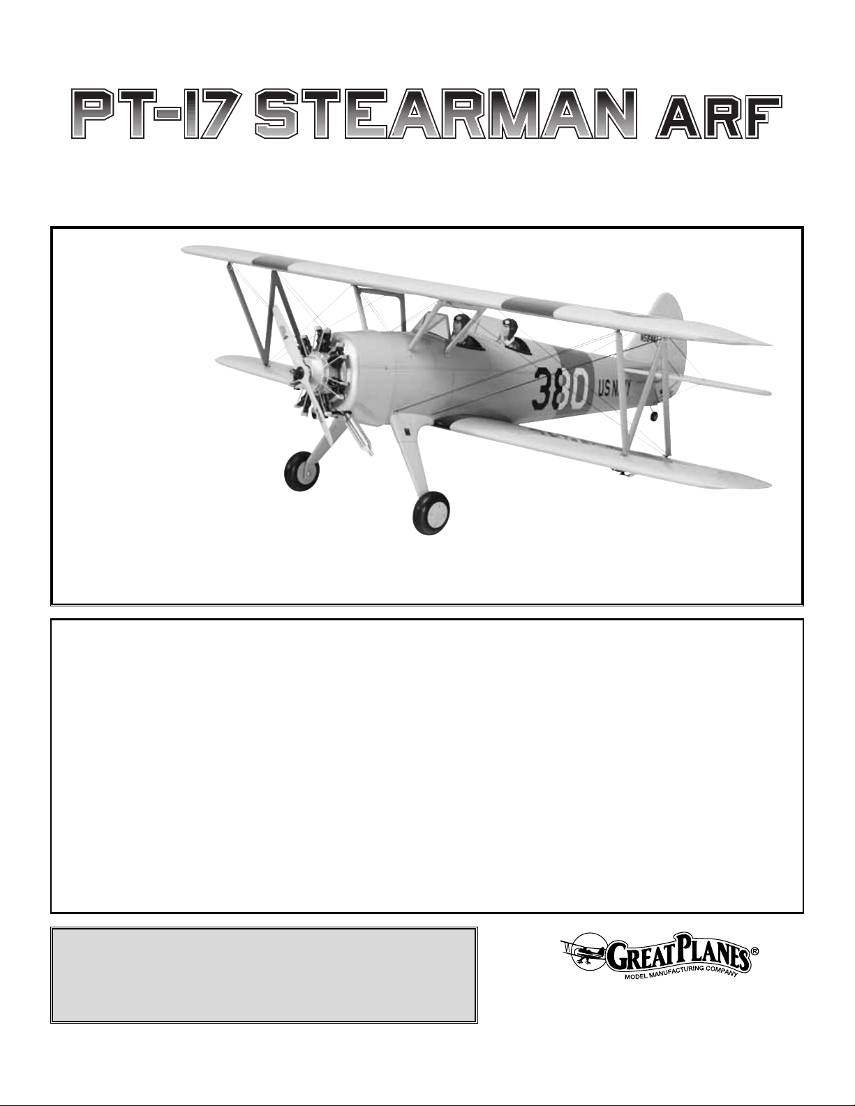
Wingspan: Top Wing:71.5 in [1815mm]
Bottom Wing: 69 in [1755mm]
Wing Area: Top WIng:762 sq in [49.1 dm2]
Bottom Wing: 704 sq in [45.4 dm2]
Weight: 14.5 – 15.5 lb [6580 – 7030 g]
Wing Loading: 23 – 24 oz/sq ft [69-74 g/dm2]
Length: 57 in [1450mm]
Radio: 4-channel with 5 servos
Engine: .91-1.08 cu in [15-17.5cc] two-stroke,
.91-1.20 cu in [19.5-23cc] four-stroke

INTRODUCTION................................................................2
IMAA ..................................................................................2
SAFETY PRECAUTIONS..................................................2
ADDITIONAL ITEMS REQUIRED.....................................3
Hardware & Accessories .............................................3
Adhesives & Building Supplies....................................3
Optional Supplies & Tools............................................4
IMPORTANT BUILDING NOTES.......................................4
KIT INSPECTION...............................................................5
METRIC CONVERSIONS..................................................6
ORDERING REPLACEMENT PARTS...............................6
IMPORTANT INFORMATION ABOUT WORKING
WITH FIBERGLASS..........................................................6
PREPARATIONS................................................................7
BUILD THE WING..............................................................7
Installing the Ailerons...................................................7
Join the Wing...............................................................7
Install the Aileron Servos & Pushrods.........................8
BUILD THE FUSELA GE..................................................11
Preparations...............................................................11
Install the Stab, Elevator, Fin & Rudder.....................11
Attach the Wing & Cabanes ......................................13
Build the Carry Handle ..............................................15
Install the Engine & Throttle Servo............................17
Install the Cowl & Dummy Radial Engine ..................18
Install the Fuel Tank...................................................21
Assemble the Nose Weight Box................................21
Install the Wheels.......................................................22
Install the Radio System............................................23
Finishing Touches ......................................................26
Optional Flying Wire Installation................................26
Apply the Decals ........................................................29
GET THE MODEL READY TO FLY..................................30
Check the Control Directions.....................................30
Set the Control Throws..............................................30
Balance the Model (C.G.)..........................................31
Balance the Model Laterally......................................31
PREFLIGHT.....................................................................31
Identify Your Model.....................................................31
Charge the Batteries ..................................................31
Balance the Propellers...............................................32
Ground Check............................................................32
Range Check.............................................................32
ENGINE SAFETY PRECAUTIONS.................................32
AMA SAFETY CODE (excerpts)....................................32
IMAA SAFETY CODE (excerpts)...................................33
CHECK LIST ....................................................................33
FLYING.............................................................................34
Fuel Mixture Adjustments..........................................34
Take Off......................................................................34
Flight..........................................................................34
Landing......................................................................35
The PT-17 Military Stear man ARF has a long and colorful
history in both military and civilian use. You will thoroughly
enjoy the wide range of capabilities of this plane as well as
its good looks. We think you will be pleased with the
attention to detail and its flight characteristics.For the latest
technical updates or manual corrections to the PT-17
Military Stearman ARF, visit the Great Planes web site at
www.greatplanes.com
. Open the “Airplanes” link, then
select the PT-17 Military Stearman ARF. If there is new
technical information or changes to this model a “tech
notice” box will appear in the upper left corner of the page.
The PT-17 Military Stearman ARF is an excellent sportscale model and is eligible to fly in IMAA events.The IMAA
(International Miniature Aircraft Association) is an
organization that promotes non-competitive flying of giantscale models. If you plan to attend an IMAA event, obtain a
copy of the IMAA Safety Code by contacting the IMAA at
the address or telephone number below, or by logging on to
their web site at
www.fly-imaa.org/imaa/sanction.html
.
IMAA
205 S. Hilldale Road
Salina, KS 67401
(913) 823-5569
1. Your PT-17 Military Stearman ARF should not be
considered a toy, but rather a sophisticated, working model
that functions very much like a full-size airplane.Because of
its performance capabilities, the PT-17 Military Stearman
ARF, if not assembled and operated correctly, could
possibly cause injury to yourself or spectators and damage
to property.
2. You must assemble the model according to the
instructions. Do not alter or modify the model, as doing so
may result in an unsafe or unflyable model. In a few cases
the instructions may differ slightly from the photos.In those
instances the written instructions should be considered
as correct.
3.You must take time to build straight, true and strong.
4. You must use an R/C radio system that is in first-class
condition, and a correctly sized engine and components
(fuel tank, wheels, etc.) throughout the building process.
PRO TECT YOUR MODEL,YOURSELF
& OTHERS...FOLLOW THESE
IMPORTANT SAFETY PRECAUTIONS
IMAA
INTRODUCTIONTABLE OF CONTENTS
2
5.You must correctly install all R/C and other components
so that the model operates correctly on the ground and in
the air.
6.You must check the operation of the model before every
flight to insure that all equipment is operating and that the
model has remained structurally sound. Be sure to check
clevises or other connectors often and replace them if they
show any signs of wear or fatigue.
7. If you are not already an experienced R/C pilot, you
should fly the model only with the help of a competent,
experienced R/C pilot.
8.While this kit has been flight tested to exceed normal use,
if the plane will be used for extremely high stress flying,
such as racing, the modeler is responsible for taking steps
to reinforce the high stress points.
9. WARNING: The cowl and wing struts included in this kit
are made of fiberglass, the fibers of which may cause eye,
skin and respiratory tract irritation. Never blow into a part to
remove fiberglass dust, as the dust will blow back into your
eyes. Always wear safety goggles, a particle mask and
rubber gloves when grinding, drilling and sanding fiberglass
parts.Vacuum the parts and the work area thoroughly after
working with fiberglass parts.
Remember:Take your time and follow the instructions to
end up with a well-built model that is straight and true.
If you have not flown this type of model before, we
recommend that you get the assistance of an experienced
pilot in your R/C club for your first flights. If you’re not a
member of a club, your local hobby shop has information
about clubs in your area whose membership includes
experienced pilots.
In addition to joining an R/C club, we strongly recommend y ou
join the AMA (Academy of Model Aeronautics). AMA
membership is required to fly at AMA sanctioned clubs.There
are over 2,500 AMA chartered clubs across the country.
Among other benefits, the AMA provides insurance to its
members who fly at sanctioned sites and events. Additionally,
training programs and instructors are available at AMA club
sites to help you get started the right way. Contact the AMA at
the address or toll-free phone number that follows.
This is the list of hardware and accessories required to
finish the PT-17 Military Stear man ARF. Order numbers are
provided in parentheses.
Engine (refer to the engine size requirements on the
cover of the manual)
4-Channel radio
(1) standard servo (throttle)
(4) servos with minimum of 54 oz/in torque (2-ailerons,
1-elevator, 1-r udder)
(2) 12" [300mm] servo extensions (for aileron servos,
HCAM2711 for Futaba
®
)
(1) Y-harness (for aileron servos, HCAM2751
or Futaba)
(1) minimum 1,000mAh receiver battery
Propeller and spare propellers (refer to your engine
manufacturer’s recommendations)
2' [600mm] large, silicone fuel tubing (GPMQ4133)
In addition to common household tools and hobby tools, this
is the “short list” of the most important items required to
build the PT-17 Military Stearman ARF.
Great Planes Pro
™
CA and Epoxy glue are recommended.
❏ R/C foam rubber (1/4" [6mm] – HCAQ1000, or 1/2"
[13mm] – HCAQ1050)
❏ 1 oz. [30g] Thin Pro CA (GPMR6002)
❏ 1 oz. [30g] Medium Pro CA+ (GPMR6008)
❏ Pro 30-minute epoxy (GPMR6047)
❏ Pro 6-minute epoxy (GPMR6045)
❏ Drill bits: 1/16" [1.6mm], 5/64" [2mm], 3/32" [2.4mm],
1/8" [3mm], #29 or 9/64" [3.6mm], 3/16" [4.8mm],
❏ 3 pkgs Stick-on segmented lead weights (GPMQ4485)
❏ #1 Hobby knife (HCAR0105)
❏ #11 Blades (5-pack, HCAR0211)
❏ Small T-pins (100, HCAR5100)
❏ R/C-56 canopy glue (JOZR5007)
❏ CA applicator tips (HCAR3780)
❏ Denatured alcohol (for epoxy cleanup)
Adhesives & Building Supplies
Hardware & Accessories
ADDITIONAL ITEMS REQUIRED
Academy of Model Aeronautics
5151 East Memorial Drive
Muncie, IN 47302
Tele: (800) 435-9262
Fax (765) 741-0057
Or via the Internet at:
http://www.modelaircraft.org
Note: We, as the kit man ufacturer , provide you with a top
quality kit and great instructions, but ultimately the quality
of your finished model depends on how you build it;
therefore, we cannot in any way guarantee the
performance of your completed model, and no
representations are expressed or implied as to the
performance or safety of your completed model.
3
❏ Flat black fuelproof paint (for cockpit)
❏ 8-32 Tap (GPMR8103)
❏ 8-32 Tap Handle (GPMR8120)
Here is a list of optional tools mentioned in the manual that
will help you build the PT-17 Military Stearman ARF.
❏ 2 oz. [57g] spray CA activator (GPMR6035)
- or -
❏ 4 oz. [113g] aerosol CA activator (GPMR634)
❏ Epoxy brushes (6, GPMR8060)
❏ Mixing sticks (50, GPMR8055)
❏ Mixing cups (GPMR8056)
❏ Builder’s Triangle Set (HCAR0480)
❏ Curved-tip canopy scissors for trimming plastic
parts (HCAR0667)
❏ Pliers with wire cutter (HCAR0630)
❏ Robart Super Stand II (ROBP1402)
❏ Hobbico
®
Duster™can of compressed air (HCAR5500)
❏ Masking tape (TOPR8018)
❏ Microballoons (TOPR1090)
❏ Threadlocker
™
thread-locking cement (GPMR6060)
❏ Denatured alcohol (for epoxy clean up)
❏ Rotary tool such as Dremel
®
❏ Rotary tool reinforced cut-off wheel (GPMR8200)
❏ Servo horn drill (HCAR0698)
❏ Dead Center
™
Engine Mount Hole Locator (GPMR8130)
❏ AccuThrow
™
Deflection Gauge (GPMR2405)
❏ CG Machine
™
(GPMR2400)
❏ Precision Magnetic Prop Balancer
™
(TOPQ5700)
❏ Fuel filler valve for glow fuel (GPMQ4160)
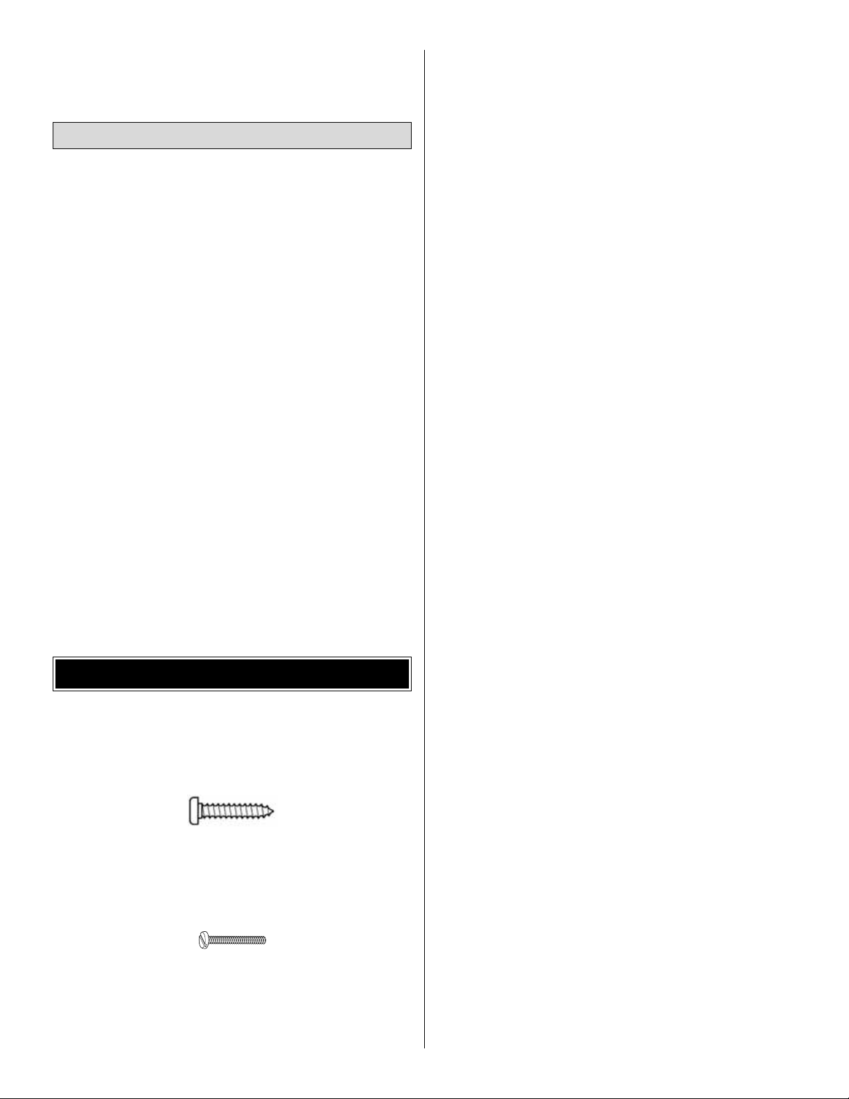
There are two types of screws used in this kit:
Sheet metal screws are designated by a n umber and a length.
This is a number six screw that is 3/4" long.
Machine screws are designated by a number, threads per
inch, and a length – for example, 4-40 x 3/4".
This is a number four screw that is 3/4" long with forty
threads per inch.
• When you see the term
test fit
in the instructions, it
means that you should first position the part on the
assembly without using any glue, then slightly modify
or
custom fit
the part as necessar y for the best fit.
• Whenever the term
glue
is written you should rely upon
your experience to decide what type of glue to use.
When a specific type of adhesive works best for that
step, the instructions will make a recommendation.
• Whenever just
epoxy
is specified you may use either
30-minute (or 45-minute) epoxy or 6-minute epo xy.When
30-minute epoxy is specified it is highly recommended
that you use only 30-minute (or 45-minute) epoxy,
because you will need the working time and/or the
additional strength.
•
Photos
and
sketches
are placed before the step they
refer to. Frequently you can study photos in following
steps to get another view of the same parts.
• The PT-17 Military Stearman ARF is factory-covered
with Top Flite®MonoKote®film. Should repairs ever be
required, MonoKote can be patched with additional
MonoKote purchased separately. MonoKote is packaged
in six-foot rolls, but some hobby shops also sell it by the
foot. If only a small piece of MonoKote is needed for a
minor patch, perhaps a fellow modeler would give you
some. MonoKote is applied with a model airplane
covering iron, but in an emergency a regular iron could
be used. A roll of MonoKote includes full instructions for
application. Following are the colors used on this model
and order numbers for six foot rolls.
Cub Yellow – TOPQ0220
Dove Gray – TOPQ0211
Sky Blue – TOPQ0206
True Red – TOPQ0227
• The stabilizer and wing incidences and engine thrust
angles have been factory-built into this model. However,
some technically minded modelers may wish to check
these measurements anyway. To view this information
visit the web site at
www.greatplanes.com
and click on
“Technical Data.”Due to manufacturing tolerances which
will have little or no effect on the way your model will fly,
please expect slight deviations between your model and
the published values.
IMPORTANT BUILDING NOTES
Optional Supplies & Tools
4
5
KIT INSPECTION
Before starting to build, take an inventory of this kit to make sure it is complete, and inspect the parts to make sure they are of
acceptable quality. If any parts are missing or are not of acceptable quality, or if you need assistance with assembly, contact
Great Planes Product Support. When reporting defective or missing parts, use the part names exactly as they are written in
the Kit Contents list on this page.
Great Planes Product Support:
Telephone: (217) 398-8970, ext. 5
Fax: (217) 398-7721
E-mail: airsupport@greatplanes.com
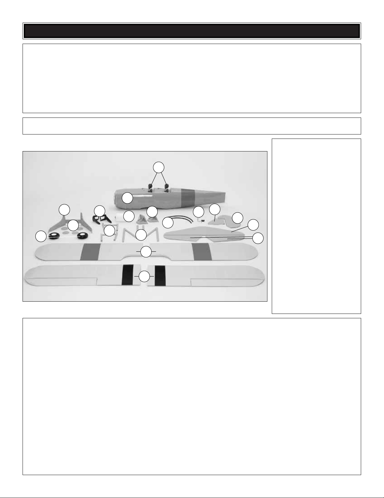
Parts Layout
Kit Contents
1. Fuselage
2. Pilots (2)
3. Main Landing Gear
4. Wheels (2)
5. Wheel Covers (4)
6. Engine Mount
7. Center Cabanes (2)
8. Fuel Tank
9. “N” Struts (2)
10. Windscreens (2)
11. Cockpit Coaming (2 pcs)
12. T ail Wheel Assembly
13. Vertical Fin
14. Rudder
15. Hor izontal Stab
16. Elevator
17. Top Wing Panels (L&R)
18. Bottom Wing Panels
(L&R w/Ailerons)
Qty
4-40 Threaded Metal Clevis ............4
3/16" x 2" Axle ................................2
Screw-Lock Pushrod Connector......1
4-40 Blind Nuts..............................20
4-40 Nuts ........................................4
8-32 Blind Nuts................................9
5/16-24 Axle Nut..............................2
1/4-20 Blind Nut ..............................2
4-40 Nylon Lock Nuts......................8
Large Nylon Control Horn ..............7
Small Nylon Control Horn ................4
1/4-20 Nylon Bolt ............................2
Nylon Clevis ....................................7
Nylon Retainer ................................1
2" x 9" Hinge Material......................1
FasLink............................................7
Clevis Retainer..............................11
Qty
#4 x 1/2" SMS ................................4
6-32 x 1/4" SHCS............................6
4-40 x 1/8" Set Screw......................1
4-40 x 1/4" SHCS............................1
#2 x 3/8" SMS ..............................28
8-32 x 3/4" SHCS............................5
4-40 x 1/2" SHCS..........................16
4-40 x 1/2" Phillips Head M/S ........8
#2 x 3/8" Wood Screw ....................8
8-32 x 1-1/4" SHCS ........................4
8-32 x 1" SHCS ..............................4
#2 x 1/2" SMS ................................4
#4 x 1" MS ......................................4
3/32" Wheel Collar ..........................1
5/32" Wheel Collar ..........................2
3/16" Wheel Collar ..........................4
1-1/4" Tail Wheel..............................1
Qty
.074 x 17-1/2" Pushrod Wire ..........1
.074 x 36" Pushrod Wire..................3
.074 x 6" Pushrod Wire....................4
#4 Lock Washers ..........................16
#4 Flat Washer ..............................24
#2 Flat Washer ..............................10
#8 Lock Washers ............................8
#8 Flat Washer ................................8
4-40 x 3/4" SHCS............................4
Dummy Radial Engine ....................1
Parts Not Photographed
1
6
3
5
10
11
12
14
9
7
8
2
16
17
18
13
15
4

1" = 25.4mm (conversion factor)
Replacement parts for the PT-17 Military Stearman ARF are
available using the order n umbers in the Replacement P arts
List that follows.The fastest, most economical service can
be provided by your hobby dealer or mail-order company.
Parts may also be ordered directly from Hobby Services,
but full retail prices and shipping and handling charges will
apply. Illinois and Nevada residents will also be charged
sales tax.
To locate a hobby dealer, visit the Great Planes web site at
www.g reatplanes.com
.Choose “Where to Buy” at the bottom of
the menu on the left side of the page. Follow the instructions
provided on the page to locate a U.S ., Canadian or International
dealer.If a hobby shop is not available, replacement parts may
also be ordered from Tower Hobbies at
www.to werhob bies.com
, or by calling toll free (800) 637-6050,
or from Hobby Services by calling (217) 398-0007, or via
facsimile at (217) 398-7721. If ordering via fax, include a Visa
®
or MasterCard®number and expiration date for payment.
Mail parts orders and payments by personal check to:
Hobby Services
3002 N Apollo Drive, Suite 1
Champaign IL 61822
Be certain to specify the order number exactly as listed in
the
Replacement Parts List
. Payment by credit card or
personal check only; no C.O.D.
If additional assistance is required for any reason, contact
the appropriate Product Support by e-mail or by telephone
at (217) 398-8970.
productsupport@greatplanes.com
REPLACEMENT PARTS LIST
Order Number Description How to Purchase
GPMA2800..........Top Wing Set..................Hobby Supplier
GPMA2801..........Bottom Wing Set............Hobby Supplier
GPMA2802..........Fuselage Kit ..................Hobby Supplier
GPMA2803..........Tail Surface Set..............Hobby Supplier
GPMA2804..........Landing Gear ................Hobby Supplier
GPMA2805..........Cowl ..............................Hobby Supplier
GPMA2806..........Dummy Radial Eng. ......Hobby Supplier
GPMA2807..........Pilot ................................Hobby Supplier
GPMA2808..........Wheel Covers ................Hobby Supplier
GPMA2809..........Windscreens ..................Hobby Supplier
GPMA2810..........Cabane Set ....................Hobby Supplier
GPMA2811..........Interplane Strut Set........Hobby Supplier
GPMA2812..........Decal Sheets..................Hobby Supplier
GPMA2473..........Metal Brackets................Hobby Supplier
GPMZ0198..........Instruction Manual........Product Support
Missing pieces..............Product Support
Full-size plans ....................Not Available
If you have never worked with fiberglass there are a few
basic things you should be aware of.
1. When you are cutting into fiberglass, be sure you are
cutting the correct place. Unlike wood, you are not able to
go back and easily fix a mistake.
2.Whenever y ou are gluing a part to the inside of fiberglass it is
important to roughen the inside surface of the fiberglass with
220-grit sandpaper, then wipe the area with alcohol. The
molding process leaves a waxy residue that can pre vent a good
bond between the glue and the parts being glued.
3. If you do not have a high-speed rotary tool such as a
Dremel tool, you should consider purchasing one or
borrowing one from a fellow modeler. This combined with a
fiberglass cut-off wheel is going to be extremely helpful in
the assembly process.
WARNING: The cowl included in this kit is made of
fiberglass, the fibers of which may cause eye, skin and
respiratory tract irritation. Never blow into a part to remove
fiberglass dust, as the dust will blow back into your eyes.
Always wear safety goggles, a particle mask and rubber
gloves when grinding, drilling and sanding fiberglass parts.
Vacuum the parts and the work area thoroughly after
working with fiberglass parts.
IMPORTANT INFORMATION ABOUT
WORKING WITH FIBERGLASS
ORDERING REPLACEMENT PARTS
METRIC CONVERSIONS
6
1/64" = .4 mm
1/32" = .8 mm
1/16" = 1.6 mm
3/32" = 2.4 mm
1/8" = 3.2 mm
5/32" = 4.0 mm
3/16" = 4.8 mm
1/4" = 6.4 mm
3/8" = 9.5 mm
1/2" = 12.7 mm
5/8" = 15.9 mm
3/4" = 19.0 mm
1" = 25.4 mm
2" = 50.8 mm
3" = 76.2 mm
6" = 152.4 mm
12" = 304.8 mm
18" = 457.2 mm
21" = 533.4 mm
24" = 609.6 mm
30" = 762.0 mm
36" = 914.4 mm
❏ 1. If you have not done so already, remove the major
parts of the kit from the box and inspect for damage. If any
parts are damaged or missing, contact Product Suppor t at
the address or telephone number listed in the
“Kit
Inspection”
section on page 5.
❏ 2. Remove the tape and separate the ailerons and flaps
from the wing and the elevators from the stab. Use a
covering iron with a covering sock on high heat to tighten
the covering if necessary. Apply pressure over sheeted
areas to thoroughly bond the covering to the wood.
Do the right bottom wing first so your work matc hes the
photos the first time through.You can do one wing at a
time, or work on them together.
❏ ❏ 1. On the right bottom wing panel, drill a 3/32"
[2.4mm] hole, 1/2" [13mm] deep in the center of each hinge
slot to allow the CA to “wick” in. Follow-up with a #11 blade
to clean out the slots. Hint: If you have one, use a highspeed rotary tool to drill the holes.
❏ ❏ 2. Use a sharp #11 blade to cut a strip of covering
from the hinge slots in the wing and aileron.
❏ ❏ 3.Cut seventeen 3/4" x 1" [19 x 25mm] hingesfrom the
CA hinge strip. Snip off the corners so they go in easier.
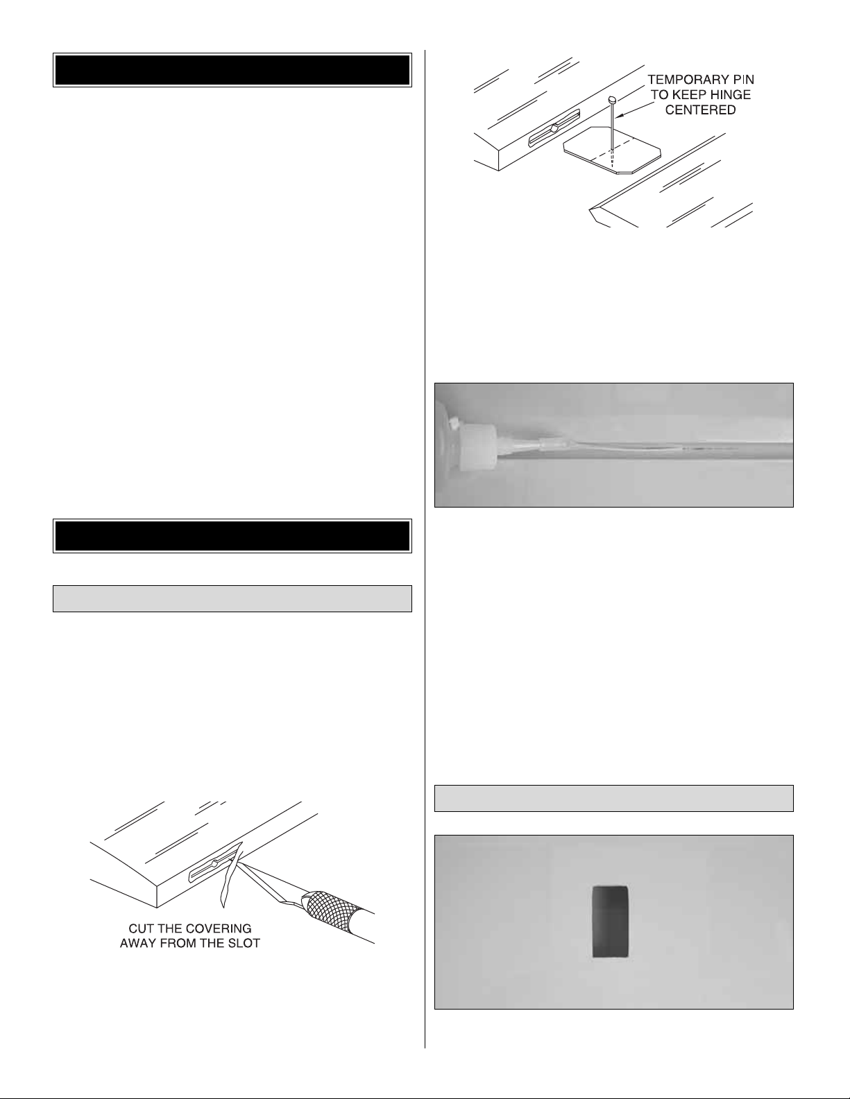
❏ ❏ 4. Test fit the ailerons to the wing with the hinges. If
the hinges don’t remain centered, stick a pin through the
middle of the hinge to hold it in position.
❏ ❏ 5. Remove any pins you may have inserted into the
hinges. Adjust the aileron so there is a small gap between the
LE of the aileron and the wing. The gap should be small, just
enough to see light through or to slip a piece of paper through.
❏ ❏ 6. Apply six drops of thin CA to the top and bottom of
each hinge. Do not use CA accelerator. After the CA has
fully cured, test the hinges by pulling on the aileron.
❏ 7. Repeat steps 1- 6 for the left bottom wing panel.
❏ ❏ 1. Cut away the covering from the servo bay in the
bottom of the right bottom wing panel.
Join the Wing
Installing the Ailerons
BUILD THE WING
PREPARATIONS
7
❏ ❏ 2. A string is taped inside the servo bay. Carefully
remove the string from the servo bay and tape it to the
outside of the wing to prevent it from dropping back into the
wing. The other end of the string is taped to the root rib.
Remove the tape, thread the string through the small hole in
the top of the wing and tape it to the wing.
❏ 3. Repeat steps 1 and 2 for the left bottom wing panel.
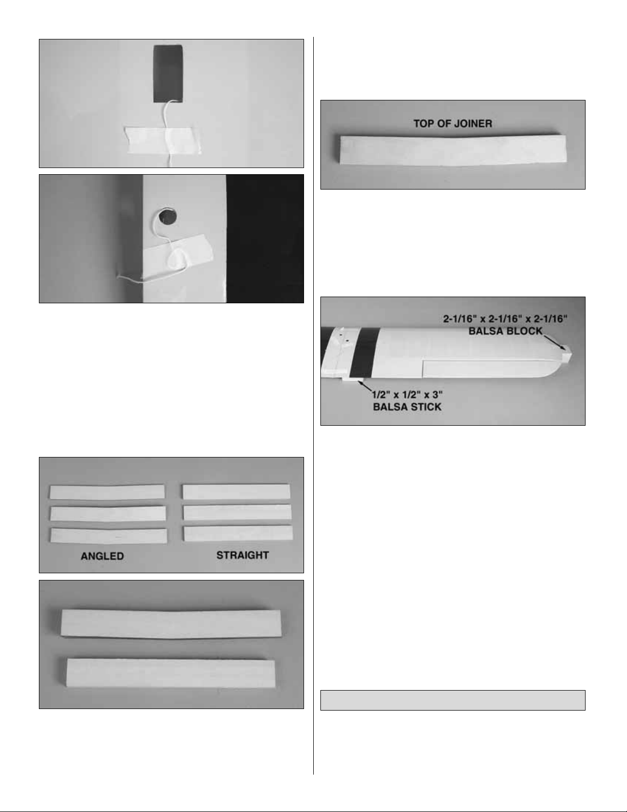
❏ 4.Locate three 1/8" [3mm] straight plywood wing joiners
and three 1/8" [3mm] angled plywood wing joiners. Using
6-minute epoxy, glue the straight ones together to form one
3/8" [9.5mm] straight wing joiner and glue the three angled
ones together forming the 3/8" [9.5mm] angled wing joiner.
❏ 5.After the glue has cured, test fit the angled wing joiner
into the bottom wing panels and the straight wing joiner into
the top wing panels. Sand the joiners as needed to get a
good fit.
❏ 6. When you are satisfied with the fit of the joiners, glue
the angled joiner into the bottom wing panels with 30-minute
epoxy. Be sure that the top of the joiner is towards the top of
the wing. When gluing the wing panels together be sure to
get glue into the joiner pockets in the wing.This can be done
by applying the glue into the pocket with a small stick.Apply
glue to the pocket, the joiner and the root rib of the wing.
Before the glue cures, set one wing half flat on your bench.
Insert the 1/2" x1/2" x 3" [13 x 13 x 76mm] balsa block under
the trailing edge of the wing that sits flat on the workbench.
Block up the wing tip of the other wing half with the 2-1/16" x
2-1/16" x 2-1/16" [52 x 52 x 52mm] balsa block included in the
kit. Put small weights on the wing half that is flat on the bench
to keep it lying flat and leave the b lock under the wing tip of the
other wing half while the glue cures.
❏ 7. Hold the wing together with masking tape while the
glue is curing. Excess epoxy can be cleaned away with
denatured alcohol and a paper towel.
❏ 8. Glue the top wing together using the straight wing
joiner and following the same gluing procedure used on the
bottom wing. Note: There is no dihedral on the top wing.
After gluing the wing together be sure it remains flat on the
workbench while the glue cures.
❏ ❏ 1. On the right lower wing, install a 12" [305mm]
servo extension onto the servo lead. Secure the extension
to the lead with tape, a piece of heat-shrink tube or some
other method to keep them from coming unplugged.
Install the Aileron Servos & Pushrods
8
❏ ❏ 2.Tie the string to the servo extension.At the root of
the wing the other end of the string is taped. Pull the string
and the servo lead through the wing. Untie the str ing from
the lead and insert the lead through the small hole you cut
the covering from. Tape the lead to the wing to prevent it
from falling back into the wing.
❏ ❏ 3. Install the servo into the servo opening. Drill
through the servo mounting holes with a 1/16" [1.6mm] drill
bit. Remove the servo from the servo opening. Install and
then remove a servo mounting screw into each of the holes
you have drilled. Apply a drop of thin CA into the holes to
harden the threads. Once the glue has cured, install the
servo into the servo opening using the hardware included
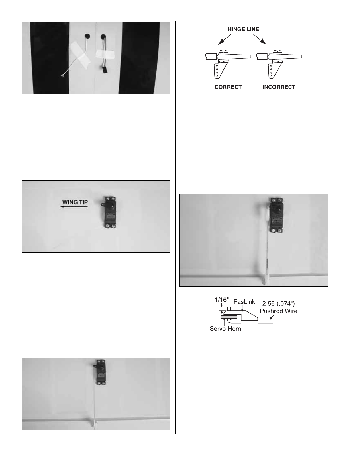
with your servo. Center the servo, then install a servo arm
as shown.The arm should be pointing towards the wing tip.
❏ ❏ 4. Place a nylon clevis in line with the last hole in the
servo arm. When positioned properly the control horn will
rest on a plywood plate in the aileron. Mark the location of
the mounting holes onto the aileron. Drill a 1/16" [1.6mm]
hole on the marks, drilling through the plywood plate but not
through the top of the aileron. Insert and remove a #2 x 3/8"
[9.5mm] screw into each of the holes.Apply a couple drops
of thin CA into the holes to harden the threads. Once the
glue has cured attach the horn to the aileron with two #2 x
3/8" [9.5mm] screws.
❏ ❏ 5. Thread a nylon clevis onto a .074 x 6" [152mm]
threaded wire 20 turns. Slide a silicone clevis retainer onto
the clevis.Install the clevis into the second hole from the end
of the control horn, then slide the silicone retainer over the
clevis. Drill a 5/64" [2mm] hole in the outer hole of the servo
arm. Center the servo and the aileron.With a fine-tip marker,
mark the wire where it aligns with the outer hole of the servo
arm. Make a 90° bend on the mark. Cut the wire so the wire
is 3/8" [9.5mm] in length after the bend.Insert the wire into the
servo arm and lock it in place with a nylon FasLink.
❏ 6. Repeat steps 1-5 for the left wing panel.
9
❏ 7. On the bottom wing, cut the covering away from the
holes in the leading edge of the wing for the nylon wing
dowels. Glue them in place with 6-minute epoxy. Wipe any
excess epoxy away with denatured alcohol.When proper ly
positioned the wing dowels should extend approximately
3/8" [9.5mm] beyond the leading edge of the wing.
❏ 8. Cut the covering from the holes on the plywood wing
bolt plate.
❏ 9. Cut the covering from the holes at the wing trailing
edge on both the top and bottom of the wing.
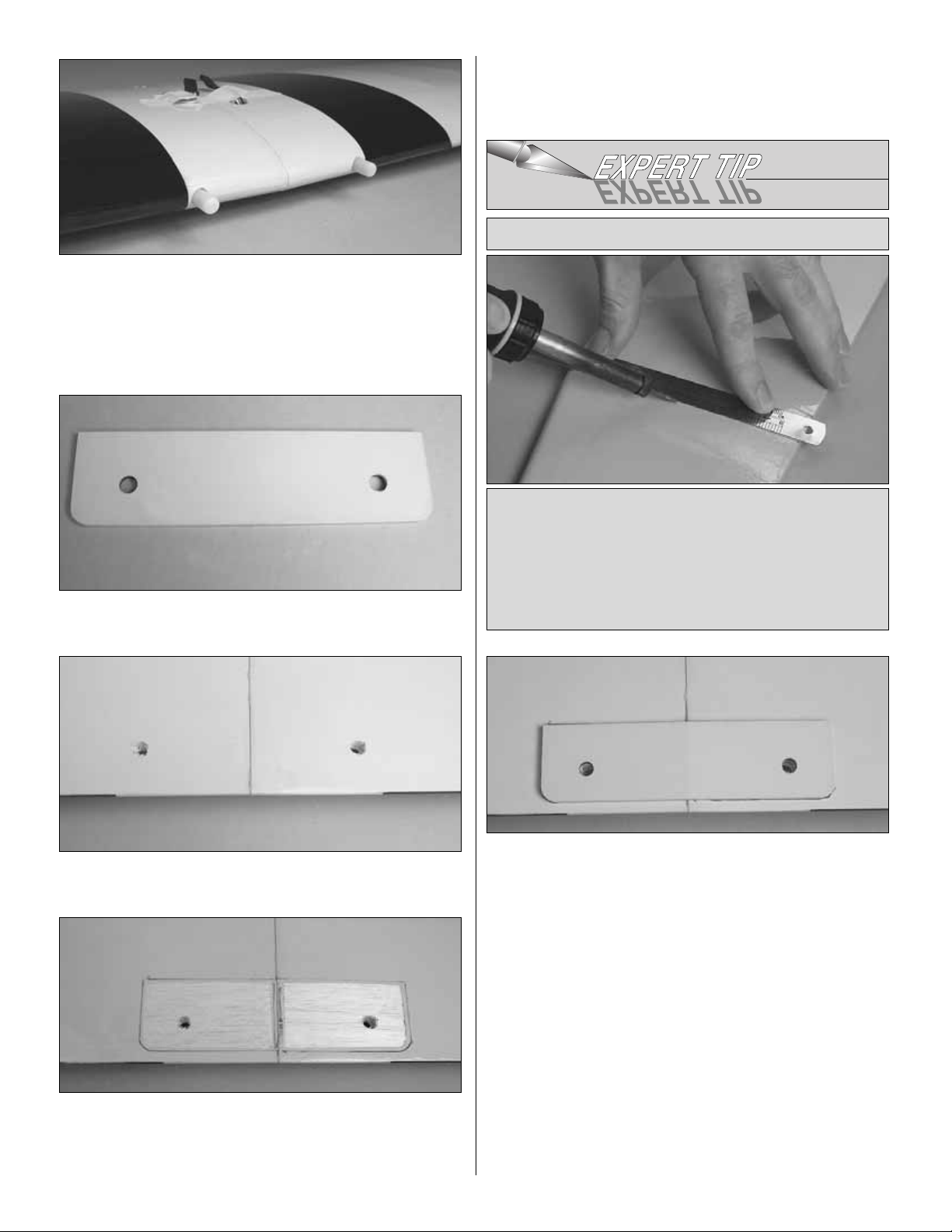
❏ 10. Place the wing bolt plate in position over the holes in the
bottom wing. Use the nylon wing bolts to help you align the
holes in the plate with the holes in the wing.Trace the outline of
the plate onto the covering with a felt-tip pen.Use a shar p #11
blade and refer the “
Expert Tip”
that follows to cut the covering
inside the lines you have drawn.Use caution not to cut through
the surface of the wing skin.Remove the covering.
❏ 11.Glue the wing bolt plate to the wing using epoxy .Use
small clamps to hold the wing bolt plate in position while the
glue cures.
Use a soldering iron to cut the covering from the stab.The
tip of the soldering iron doesn’t have to be sharp, but a
fine-tip does work best. Allow the iron to heat fully. Use a
straightedge to guide the soldering iron at a rate that will
just melt the covering and not burn into the wood. The
hotter the soldering iron, the faster it must travel to melt a
fine cut. Peel off the covering.
HOW TO CUT COVERING FROM BALSA
10
❏ 1. Remove the belly pan from the bottom of the fuselage.
Install the landing gear to the fuselage with five 8-32 x 3/4"
[19mm] socket head cap screws .Apply a drop of Threadlock er
to each bolt before installing them.
❏ 2. Glue the belly pan back in place with a few dabs of
silicone glue. Using silicone will allow you to remove the
belly pan easily should you ever have to get access to the
landing gear bolts.
We will come back and do the installation of the wheels later.
Having the landing gear installed at this time will make it easier
to handle the fuselage on the workbench.
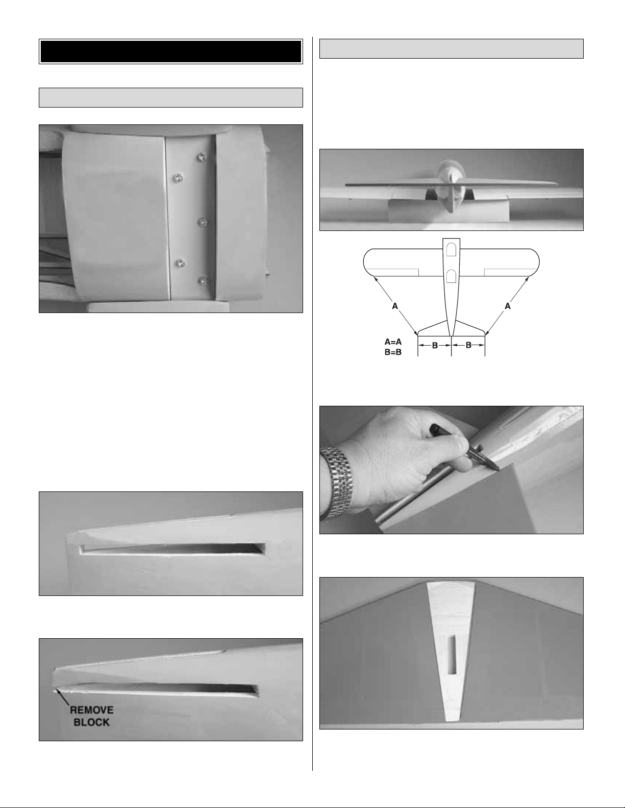
❏ 3. Cut the covering from the fuselage where the horizontal
stabilizer fits into the fuselage.
❏ 4. Cut the covering and the wood block from the back
of the horizontal stabilizer saddle.
❏ 1.Temporarily attach the lower wing to the fuselage with the
1/4-20 nylon bolts. Slide the horizontal stabilizer into the slot in
the fuselage. Stand back and look at the stab in relation to the
wing.The stab should be parallel with the wing. If not, sand the
stab saddle until the stab and wing are aligned.
❏ 2. Measure the distance from the tip of the stab to the tip of
each wing. Adjust the position of the stab until they are equal.
❏ 3. Using a felt-tip pen, mark the outline of the fuselage
on the top and the bottom of the stab.
❏ 4. Cut the covering on the top and bottom of the stab
inside the lines you have dr a wn.Use the same technique for
removing the covering from the wing.
Install the Stab, Elevator, Fin & Rudder
Preparations
BUILD THE FUSELAGE
11
 Loading...