

Page 1
WARRANTY
Great Planes
®
Model Manufacturing Co. guarantees this kit to be free from defects in both material and workmanship at the date of
purchase.This warranty does not cover an y component parts damaged by use or modification.In no case shall Great Planes’ liability
exceed the original cost of the purchased kit. Further, Great Planes reserves the right to change or modify this warranty without
notice.
In that Great Planes has no control over the final assembly or material used for final assembly, no liability shall be assumed nor
accepted for any damage resulting from the use by the user of the final user-assemb led product.By the act of using the user-assembled
product, the user accepts all resulting liability.
If the buyer is not prepared to accept the liability associated with the use of this product, the buyer is advised to return this
kit immediately in new and unused condition to the place of purchase.
READ THROUGH THIS MANUAL BEFORE STARTING
CONSTRUCTION. IT CONTAINS IMPORTANT
INSTRUCTIONS AND WARNINGS CONCERNING
THE ASSEMBLY AND USE OF THIS MODEL.
GPMZ0243 for GPMA1347 V1.0 Entire Contents © Copyright 2002
1610 Interstate Drive Champaign, IL 61822
(217) 398-8970, Ext. 2
airsupport@greatplanes.com
INSTRUCTION MANUAL
Wingspan: 79-3/4 in [2030mm]
Wing Area: 690 sq in [44.5 dm
2
]
Weight: 8.5 – 9 lb [3850 – 4080g]
Wing Loading: 28 – 30 oz/sq ft [85 – 92g/dm
2
]
Length: 52 in [1320mm]
Radio: 5-channel with 7 servos
Engine: .61 – .75 cu in [10 – 12cc] 2-stroke,
.91 cu in [15cc] 4-stroke
Page 2

INTRODUCTION................................................................2
IMAA ..................................................................................2
SAFETY PRECAUTIONS..................................................3
DECISIONS YOU MUST MAKE ........................................3
Radio Equipment.........................................................3
Engine Recommendations...........................................4
ADDITIONAL ITEMS REQUIRED.....................................4
Hardware & Accessories .............................................4
Adhesives & Building Supplies....................................4
Optional Supplies & Tools............................................4
IMPORTANT BUILDING NOTES.......................................4
COMMON ABBREVIATIONS............................................5
METRIC/INCH RULER ......................................................5
ORDERING REPLACEMENT PARTS...............................5
KIT CONTENTS .................................................................6
IMPORTANT INSTRUCTIONS ABOUT
WORKING WITH FIBERGLASS .......................................7
PREPARATIONS................................................................7
BUILD THE WING..............................................................7
Install the Flaps & Ailerons..........................................7
Install the Flap & Aileron Servo...................................8
Install the Flap & Aileron Hardware & Pushrods.......11
Join the Wings...........................................................12
ASSEMBLE THE FUSELAGE.........................................13
Install the Pushrod Tubes & Fuselage Formers.........13
Install the Horizontal Stab, Elevators,
Rudder & Pushrods ...................................................15
INSTALL THE ENGINE & MUFFLER..............................17
Install the Engine.......................................................17
Join the Muffler..........................................................18
Install the Nose Wheel...............................................19
Install the Main Landing Gear....................................23
Install the Fuel Tank...................................................25
INSTALL THE RADIO SYSTEM......................................25
Install the Receiver & Battery....................................28
Receiver Antenna Routing .........................................28
INST ALL THE CO WL.......................................................29
GET THE MODEL READY TO FLY..................................30
Check the Control Directions.....................................30
Set the Control Throws..............................................30
Balance the Model (C.G.)..........................................31
Balance the Model Laterally......................................32
PREFLIGHT.....................................................................32
Identify Your Model.....................................................32
Charge the Batteries ..................................................32
Balance the Propellers...............................................32
Ground Check............................................................32
Range Check.............................................................32
ENGINE SAFETY PRECAUTIONS.................................33
AMA SAFETY CODE (excerpt)......................................33
IMAA SAFETY CODE (excerpt).....................................33
CHECK LIST ....................................................................35
FLYING.............................................................................35
Fuel Mixture Adjustments..........................................35
Takeoff .......................................................................36
Flight..........................................................................36
Landing......................................................................36
ENGINE MOUNT TEMPLATE..........................................39
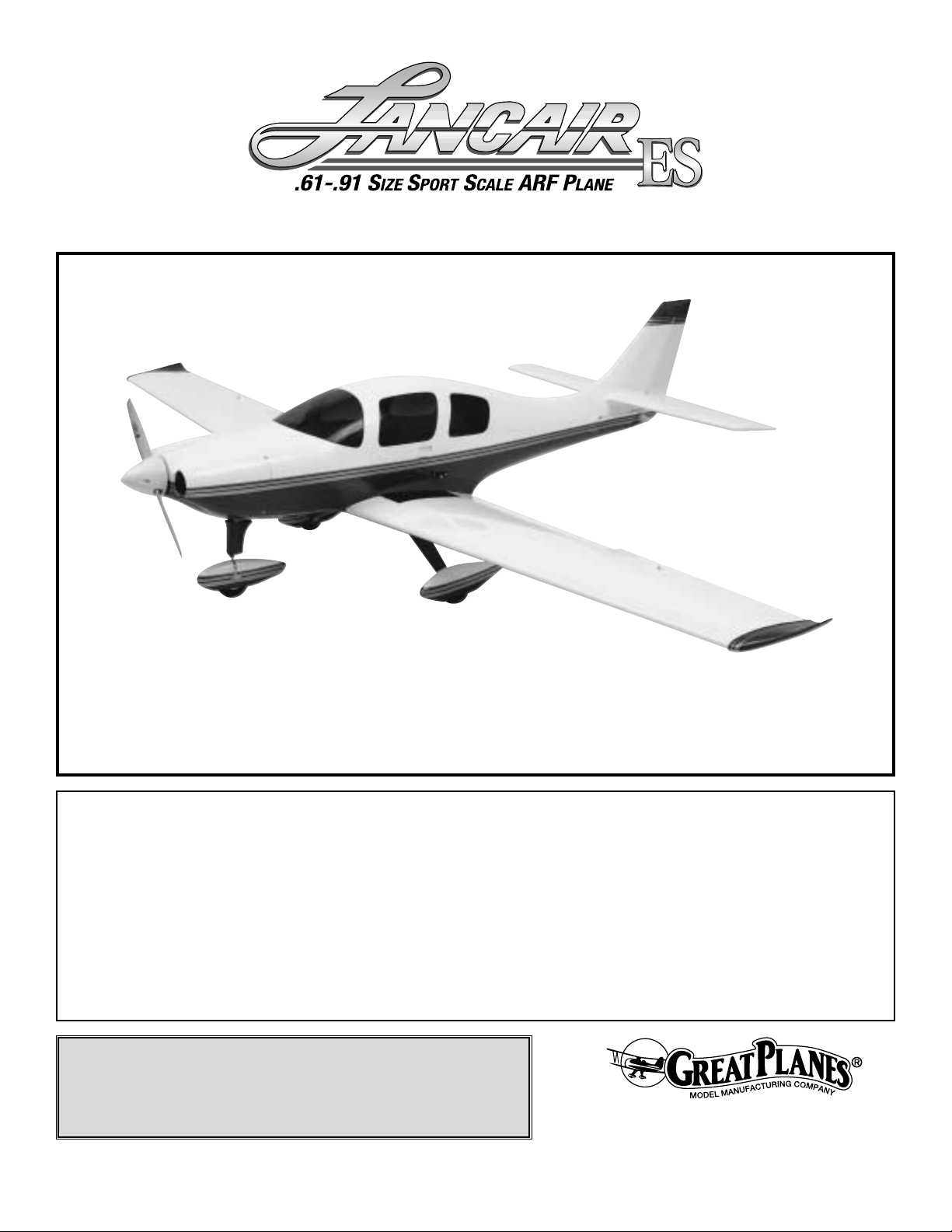
Of the many airplanes flying today, the Lancair (Lance-air)
is considered by many to be a “Modern Classic.” With its
sleek, clean lines, it has a very graceful appearance both on
the ground and in the air.Great Planes is proud to bring you
this wonderful classic in an easy to fly model that will
impress you by the way it flies and its good looks in the air.
We are sure you will get years of enjoyment from your
Lancair.
For the latest technical updates or manual corrections to the
Lancair, visit the web site listed below and select the Great
Planes Lancair ARF. If there is new technical information or
changes to this model, a “tech notice”box will appear in the
upper left corner of the page.
http://www.greatplanes.com/airplanes/index.html
For information on the full-size Lancair visit this web site:
http://www.lancair.com
The Great Planes Lancair is an excellent sport-scale model
and is eligible to fly in IMAA ev ents.The IMAA (International
Miniature Aircraft Association) is an organization that
promotes non-competitive flying of giant-scale models. If
you plan to attend an IMAA event, contact the IMAA for a
copy of the IMAA Safety Code at the address or telephone
number below.
IMAA
205 S. Hilldale Road
Salina, KS 67401
(913) 823-5569
www.fly-imaa.org/imaa/sanction.html
Scale Competition
Though the Great Planes Lancair is an ARF and may not
have the same level of detail as an “all-out” scratch-built
competition model, it is a scale model nonetheless and is
therefore eligible to compete in the
Fun Scale
class in AMA
competition (we receive many favorable reports of Great
Planes ARFs in scale competition!) In Fun Scale, the
“builder of the model”rule does not apply .To receive the five
points for scale documentation, the only proof required that
a full-size aircraft of this type in this paint/markings scheme
did exist is a single sheet such as a kit box cover from a
plastic model, a photo, or a profile painting, etc.If the photo
is in black and white, other written documentation of color
must be provided.Contact the AMA for a rule book with full
details.
IMAA
INTRODUCTIONTABLE OF CONTENTS
2
Page 3
If you would like photos of the full-size Lancair for scale
documentation, or if you would like to study the photos to
add more scale details, photo packs are available from:
Bob’s Aircraft Documentation
3114 Y uk on A ve
Costa Mesa, CA 92626
Telephone: (714) 979-8058
Fax:(714) 979-7279
e-mail: www.bobsairdoc.com
1.Your Lancair should not be considered a toy, but rather a
sophisticated, working model that functions very much like
a full-size airplane. Because of its performance capabilities,
the Lancair, if not assembled and operated correctly, could
possibly cause injury to yourself or spectators and damage
to property.
2. You must assemble the model according to the
instructions. Do not alter or modify the model, as doing so
may result in an unsafe or unflyable model. In a few cases
the instructions may differ slightly from the photos.In those
instances the written instructions should be considered as
correct.
3.You must take time to build straight, true and strong.
4. You must use an R/C radio system that is in first-class
condition, and a correctly sized engine and components
(fuel tank, wheels, etc.) throughout the building process.
5.You must correctly install all R/C and other components
so that the model operates correctly on the ground and in
the air.
6.You must check the operation of the model before every
flight to insure that all equipment is operating and that the
model has remained structurally sound. Be sure to check
clevises or other connectors often and replace them if they
show any signs of wear or fatigue.
7. If you are not already an experienced R/C pilot, you
should fly the model only with the help of a competent,
experienced R/C pilot.
8.While this kit has been flight tested to exceed normal use,
if the plane will be used for extremely high stress flying,
such as racing, the modeler is responsible for taking steps
to reinforce the high stress points.
Remember: Take your time and follow the instructions
to end up with a well-built model that is straight
and true.
If you have not flown this type of model before, we
recommend that you get the assistance of an experienced
pilot in your R/C club for your first flights. If you’re not a
member of a club, your local hobby shop has information
about clubs in your area whose membership includes
experienced pilots.
In addition to joining an R/C club, we strongly recommend
you join the AMA (Academy of Model Aeronautics). AMA
membership is required to fly at AMA sanctioned clubs.
There are over 2,500 AMA chartered clubs across the
country .Among other benefits, the AMA provides insurance
to its members who fly at sanctioned sites and events.
Additionally, training programs and instructors are available
at AMA club sites to help you get started the right way.
Contact
the AMA at the address or toll-free phone number below:
This is a partial list of items required to finish the Lancair
that may require planning or decision making before
starting to build. Order numbers are provided in
parentheses.
The Lancair requires a minimum of a 5-channel radio and
receiver, plus: seven servos producing a minimum of 41oz.in of torque, two Y-harness connectors, two 24" [610mm]
and two 12" [305mm] servo extensions.
Radio Equipment
DECISIONS YOU MUST MAKE
Academy of Model Aeronautics
5151 East Memorial Drive
Muncie, IN 47302
Tele: (800) 435-9262
Fax (765) 741-0057
Or via the Internet at:
http://www.modelaircraft.org
We, as the kit manufacturer, provide you with a top
quality kit and instructions, but ultimately the quality and
flyability of your finished model depends on how y ou build
it; therefore, we cannot in any way guarantee the
performance of your completed model, and no
representations are expressed or implied as to the
performance or safety of your completed model.
PRO TECT YOUR MODEL,Y OURSELF
& OTHERS...FOLLOW THESE
IMPORTANT SAFETY PRECAUTIONS
3
Page 4
The recommended engine size range for the Lancair is
.61 – .75 cu in [10 – 12cc] two-stroke, .91 cu in [15cc] fourstroke. We flew our prototype with the O.S.®.61 FX
(OSMG0561). We found this to be more than adequate
power. This coupled with the Top Flite®In-Cowl muffler
(TOPQ7917), exhaust header (TOPQ7920), and exhaust
deflector (HCAP2180) not only provided the correct power
combination but also makes for a very nice scale engine
installation. If an engine in the upper end of the size range
is used, remember that this is a scale model that is intended
to fly at scale-like speeds, so throttle management should
be practiced.
In addition to the items listed in the
“Decisions Y ou Must
Make”
section, the following is a list of hardware and
accessories required to finish the Lancair. Order numbers
are provided in parentheses.
❏ Engine and suitable propellers
❏ Exhaust deflector (HCAP2180)
❏
(2) 12" [300mm] Servo extension (HCAM2711 for Futaba®)
❏ (2) 24" [610mm] Serv o e xtension (HCAM2721 f or
Futaba)
❏ (2) Y-harness (HCAM2751 for Futaba)
❏ R/C foam rubber (1/4" [6mm] – HCAQ1000, or 1/2"
[13mm] – HCAQ1050)
❏ #64 Rubber bands (1/4 lb [113g] box, HCAQ2020)
In addition to common household tools and hobby tools, this
is the “short list” of the most important items required to
build the Lancair.
Great Planes Pro™CA and Epoxy glue
are recommended.
❏ 1/2 oz. [15g] Thin Pro CA (GPMR6001)
❏ 1 oz. [30g] Medium Pro CA+ (GPMR6008)
❏ Pro 30-minute epoxy (GPMR6047)
❏ Pro 6-minute epoxy (GPMR6045)
❏ Microballoon filler (TOPR1090)
Here is a list of optional tools mentioned in the manual that
will help you build the Lancair.
❏ Drill bits:1/16" [1.6mm], 5/64" [2mm], 3/32" [2.4mm],
1/8" [3.2mm], 5/32" [4mm], 3/16" [4.8mm],
7/32" [5.6mm], 1/4" [6.4mm]
❏ #11 Blades (5-pack, HCAR0211)
❏ 3 Standard silicone tubing (GPMQ4131)
❏ 2 oz. [57g] Spray CA activator (GPMR6035)
❏ CA applicator tips (HCAR3780)
❏ CA debonder (GPMR6039)
❏ Epoxy brushes (6, GPMR8060)
❏ Mixing sticks (50, GPMR8055)
❏ Mixing cups (GPMR8056)
❏ 36" metal ruler (HCAR0475)
❏ Robar t Super Stand II (ROBP1402)
❏ Hobbico
®
Duster™can of compressed air (HCAR5500)
❏ Masking tape (TOPR8018)
❏ Threadlocker thread locking cement (GPMR6060)
❏ Rubbing alcohol (for epoxy clean up)
❏ Switch & Charge Jack Mounting Set (GPMM1000)
❏ Rotar y tool such as Dremel
®
Moto-Tool
®
❏ Rotar y tool reinforced cut-off wheel (GPMR8200)
❏ Ser vo horn drill (HCAR0698)
❏ Dead Center
™
Engine Mount Hole Locator (GPMR8130)
❏ Accu-Throw
™
Deflection Gauge (GPMR2405)
❏ CG Machine
™
(GPMR2400)
❏ Precision Magnetic Prop Balancer
™
(TOPQ5700)
❏ Sealing Iron (TOPR2100)
❏ Sandpaper–100, and 220-grit
❏ 6-32 T ap
• There are two types of screws used in this kit:
Sheet metal screws are designated by a number and a
length. For example #6 x 3/4".
This is a number six screw that is 3/4" long.
Machine screws are designated by a number, threads per
inch, and a length.SHCS is just an abbreviation for “socket
head cap screw” and that is a machine screw with a socket
head. For example 4-40 x 3/4".
This is a number four screw that is 3/4" long with forty
threads per inch.
• When you see the term
test fit
in the instructions, it
means that you should first position the part on the
assembly without using any glue, then slightly modify or
custom fit
the part as necessar y for the best fit.
IMPORTANT BUILDING NOTES
Optional Supplies & Tools
Adhesives & Building Supplies
Hardware & Accessories
ADDITIONAL ITEMS REQUIRED
Engine Recommendations
4
Page 5
• Whenever the term
glue
is written you should rely
upon your experience to decide what type of glue to use.
When a specific type of adhesive works best for that step,
the instructions will make a recommendation.
• Whenever just
epoxy
is specified you may use
either
30-minute (or 45-minute) epoxy or6-minute epoxy. When
30-minute epoxy is specified it is highly recommended that
you use only 30-minute (or 45-minute) epoxy, because you
will need the working time and/or the additional strength.
• Photos and sketches are placed before the step they
refer to. Frequently you can study photos in following steps
to get another view of the same parts.
• The Lancair is factory-covered with Top Flite
MonoKote®film.Should repairs ever be required, MonoK ote
can be patched with additional MonoKote purchased
separately.MonoKote is packaged in six-foot rolls, b ut some
hobby shops also sell it by the foot. If only a small piece of
MonoKote is needed for a minor patch, perhaps a fellow
modeler would give you some. MonoKote is applied with a
model airplane covering iron, but in an emergency a regular
iron could be used. A roll of MonoKote includes full
instructions for application.Following are the colors used on
this model and order numbers for six foot rolls.
White–TOPQ0204, Black–TOPQ0208
Sapphire Blue–TOPQ0226, Metallic Gold–TOPQ0404
Fuse = Fuselage
Stab = Horizontal Stabilizer
Fin = Ver tical Fin
LE = Leading Edge
TE = Trailing Edge
LG = Landing Gear
Ply = Plywood
" = Inches
COMMON ABBREVIATIONS
5
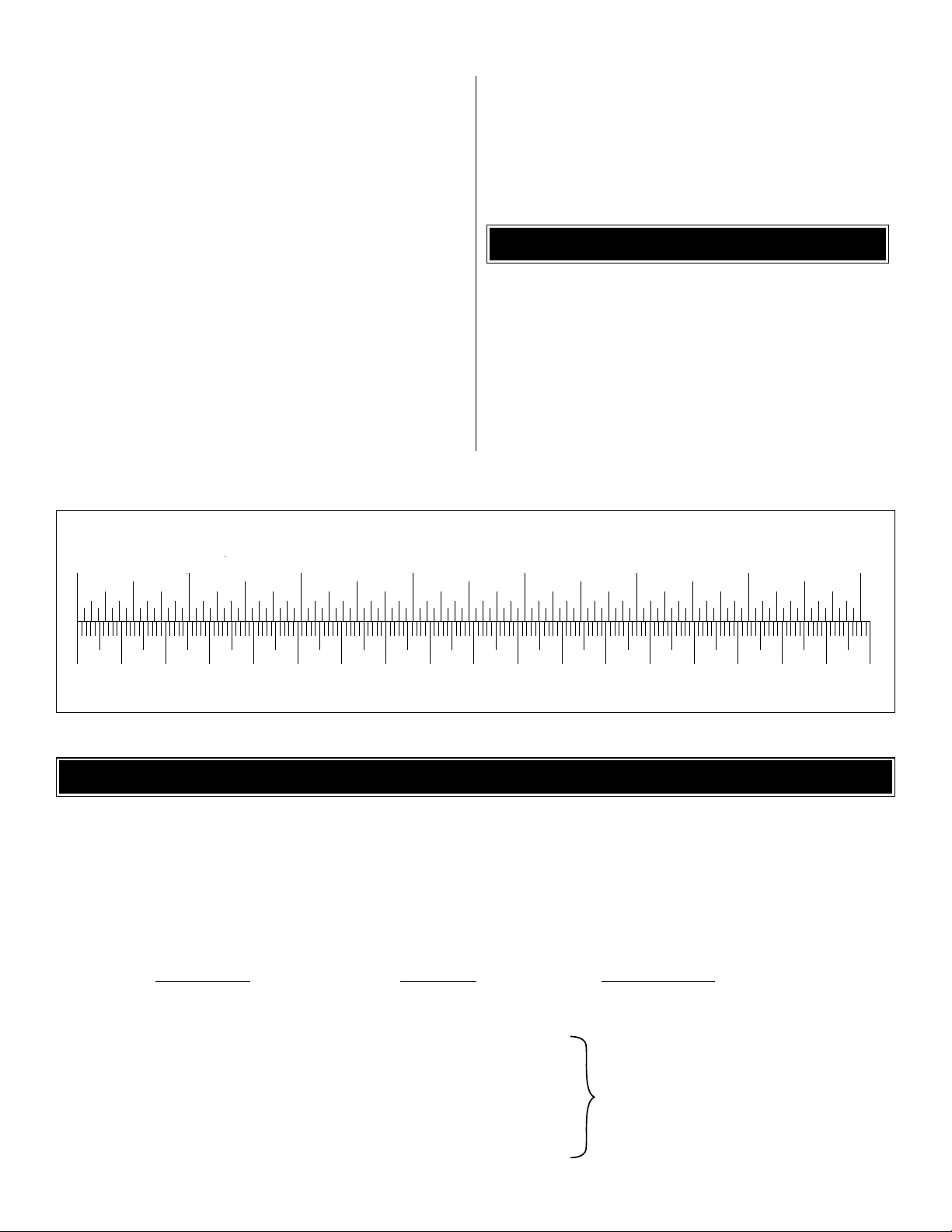
0" 1" 2" 3" 4" 5" 6" 7"
0 10 20 30 40 50 60 70 80 90 100 110 120 130 140 150 160 170 180
Inch Scale
Metric Scale
To convert inches to millimeters, multiply inches by 25.4
To order replacement parts for the Great Planes Lancair ARF, use the order numbers in the Replacement Parts List that
follows. Replacement parts are available only as listed. Not all parts are available separately (an aileron cannot be
purchased separately, but is only available with the wing kit). Replacement par ts are not available from Product Support,
but can be purchased from hobby shops or mail order/Internet order firms. Hardware items (screws, nuts, bolts) are also
available from these outlets. If you need assistance locating a dealer to purchase parts, visit www.greatplanes.com and
click on “Where to Buy.” If this kit is missing parts, contact Great Planes Product Support.
Replacement Parts List
Or
der Number Description How to Purchase
Missing pieces............................Contact Product Suppor t
Instruction manual ......................Contact Product Support
Full-size plans............................Not available
GPMA2320............................................Wing Kit
GPMA2321............................................Fuse Kit
GPMA2322............................................Tail Set
GPMA2323............................................Cowl
GPMA2327............................................Canopy
GPMA2324............................................Landing Gear
GPMA2325............................................Wheel Pants
GPMA2326............................................Tail Joiner Tube End Rod
ORDERING REPLACEMENT PARTS
.............
Contact Your Hobby
Supplier to Purchase
These Items
Page 6
6
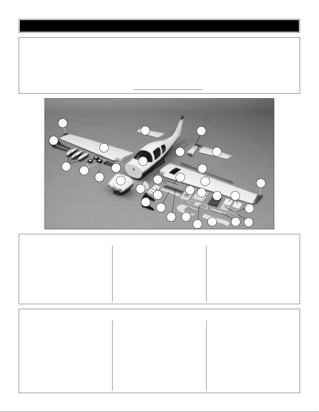
1. Fiberglass Fuselage
2 Left Wing/Aileron and Flap
3. Right Wing/Aileron and Flap
4. Left Stabilizer
5. Right Stabilizer
6. Rudder
7. Cowl
8. Fiberglass Wing Tips
9. Fiberglass Wheel Pants
10. Main Landing Gear
11. Wheels
12. Nose Gear Wire
13. Fiberglass Exhaust Air Panel
14. Spinner
15. Pushrod Wires
16. Engine Mount
17. Carbon Fiber Anti-Rotation Pin
18. Aluminum Tube
19. Wing Bolt Plate
20. Flap Covers
21. Forward Former
22. Rear Former
23. Serv o Tray (2)
24. Receiver/Battery Tra y (2)
25. Engine Baffle
26. CA Hinge Strip Mater ial
27. Wing Joiner (2)
28. Nose Wire Fairing
29. Aileron Covers
30. Nylon Hardware Bag
31. Metal Hardware Bag
32. Outer Pushrod Tubes
(4) 5/16" x 3/4" 7/8" Ser vo Mount Blocks
(2) 5/32" x 2" Axle
(1) Brass Screw-Lock Pushrod Connector
(2) 4-40 Blind Nuts
(4) 8-32 Blind Nuts
(2) 5/16-24 Lock Nut
(2) 1/4-20 Blind Nuts
(3) Large Nylon Control Hor n
(4) Small Nylon Control Hor n
(1) Nose Gear Bearing
(2) 1/4-20 Nylon Wing Bolt
(1) Nylon Steering Control Ar m
(8) Nylon Clevis
(1) Nylon Landing Gear Strap
(1) Nylon Retainer For Screw-Lock Pushrod
Connector
(1) 2" x 9" CA Hinge Material
(8) Nylon FasLinks
(8) Silicone Clevis Retainer
(1) 4-40 x 1/8" Socket Head Cap Screws
(4) 2-56 x 5/8" Machine Screw
(8) #4 x 1/2" Sheet Metal Screw
(5) 6-32 X 1/8" Set Screw
(3) 6-32 x 1/4" Socket Head Cap Screws
(2) #4 x 5/8" Sheet Metal Screw
(2) 4-40 x 5/8" Phillips Pan Head Screws
(40) #2 x 3/8" Sheet Metal Screw
(4) 2-56 x 3/4" Socket Head Cap Screws
(4) 6-32 x 1" Socket Head Cap Screws
(4) 8-32 x 1" Socket Head Cap Screws
(4) #2 x 1/2" Sheet Metal Screw
(8) 5/32" Wheel Collar
(4) .074 x 36" Wire Threaded One End
(4) .074 x 6" Pushrod Wire
(5) #6 Flat Washers
(22) #2 Flat Washers
(4) #8 Lock Washers
(4) #8 Flat Washers
(4) #6 Lock Washers
Kit Contents (Photographed)
Kit Contents (Not Photographed)
Before starting to build, use the Kit Contents list to take an inventory of this kit to make sure it is complete, and inspect the
parts to make sure they are of acceptable quality. If any parts are missing or are not of acceptable quality, or if you need
assistance with assembly, contact Great Planes Product Support. When reporting defective or missing parts, use the part
names exactly as they are written in the Kit Contents list on this page.
Great Planes Product Support:
Telephone: (217) 398-8970
Fax: (217) 398-7721
E-mail: air
support@greatplanes.com
KIT CONTENTS
1
2
3
4
5
7
9
24
23
32
25
26
27
29
28
31
30
22
19
21
20
16
12
11
13
10
14
17
18
15
6
8
8
Page 7
If you have never worked with fiberglass there are a few
basic things you should be aware of:
• When you are cutting into fiberglass, be sure you are
cutting the correct place. Unlike wood, you are not able to
go back and easily fix a mistake.
• Whenever you are gluing a part to the inside of fiberglass
it is important to roughen the inside surface of the
fiberglass with 220-grit sandpaper and then wipe the area
with alcohol. The molding process leaves a waxy residue
that can prevent a good bond between the glue and the
parts being glued.
• If you do not have a high-speed rotary tool such as a
Dremel®tool you should consider purchasing one or
borrowing one from a fellow modeler.This combined with
a fiberglass cut-off wheel is going to be extremely helpful
in the assembly process.
WARNING:The cowl, wheel pants and fuselage included in
this kit are made of fiberglass, the fibers of which may cause
eye, skin and respiratory tract irritation. Never blow into a
part to remove fiberglass dust, as the dust will blow back
into your eyes. Always wear safety goggles, a particle mask
and rubber gloves when grinding, drilling and sanding
fiberglass parts. Vacuum the parts and the work area
thoroughly after working with fiberglass parts.
❏ 1. If you have not done so already, remove the major
parts of the kit from the box and inspect for damage. If any
parts are damaged or missing, contact Product Suppor t at
the address or telephone number listed in the“Kit
Contents”
section on page 6.
❏ 2. Remove the tape and separate the ailerons and flaps
from the wing and the elevators from the stab. Use a
covering iron with a covering sock on high heat to tighten
the covering if necessary. Apply pressure over sheeted
areas to thoroughly bond the covering to the wood.
Do the right wing first so your work matc hes the photos
the first time through.You can do one wing at a time , or
work on them together.
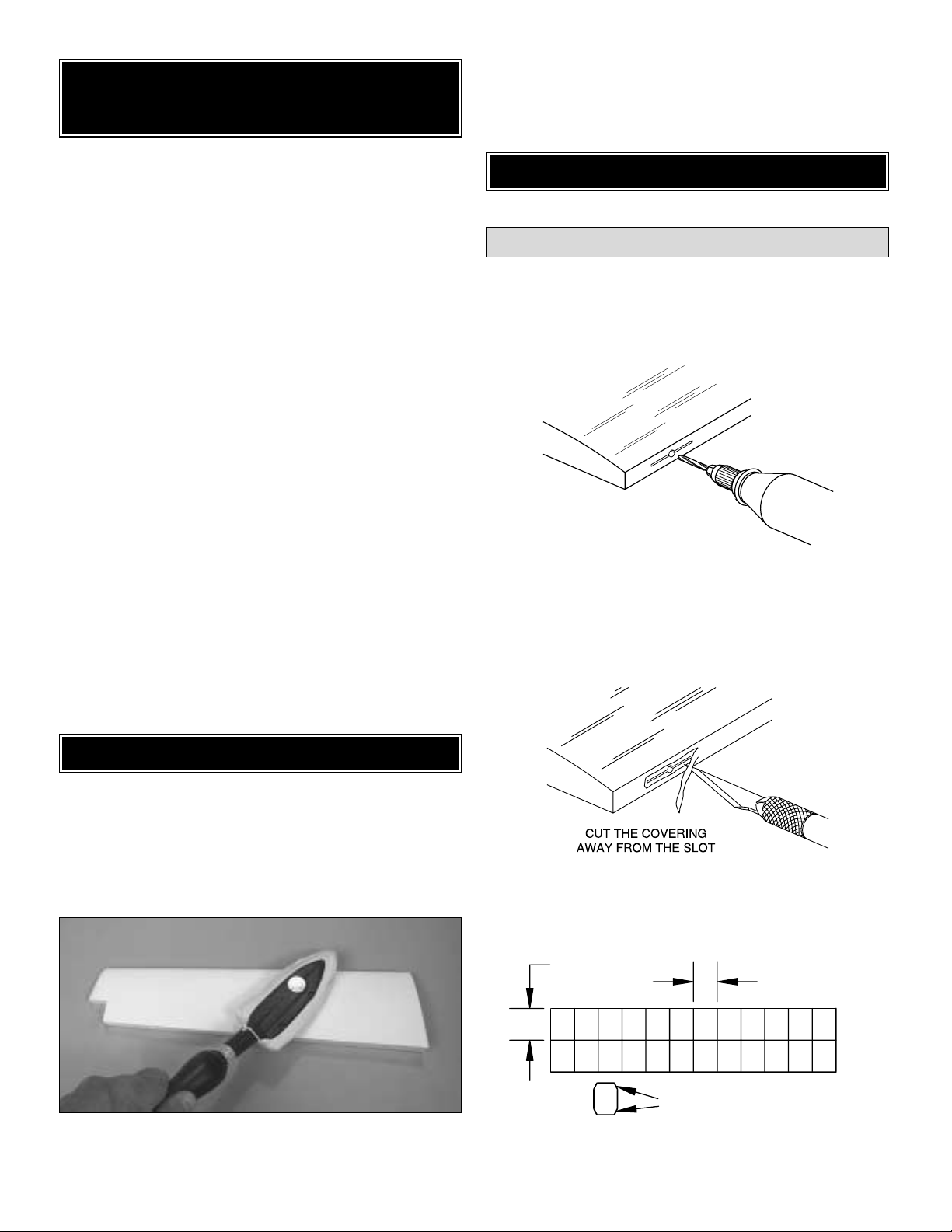
❏❏1.Drill a 3/32" [2.4mm] hole, 1/2" [12.7mm] deep in the
center of each hinge slot to allow the CA to “wick”in. Followup with a #11 blade to clean out the slots.Hint: If you have
one, use a high-speed rotary tool to drill the holes.
❏❏2.Use a sharp #11 blade to cut a strip of covering from
the hinge slots in the wing and aileron.
❏❏3. Cut seven 3/4" x 1" [19 x 25mm] hinges from the
CA hinge strip. Snip off the corners so they go in easier.
DRILL A 3/32" HOLE
1/2" DEEP, IN CENTER
OF HINGE SLOT
Install the Flaps & Ailerons
BUILD THE WING
PREPARATIONS
IMPORTANT INFORMATION ABOUT
WORKING WITH FIBERGLASS
7
1" [25mm]
3/4" [19mm]
Trim the Corners
Page 8
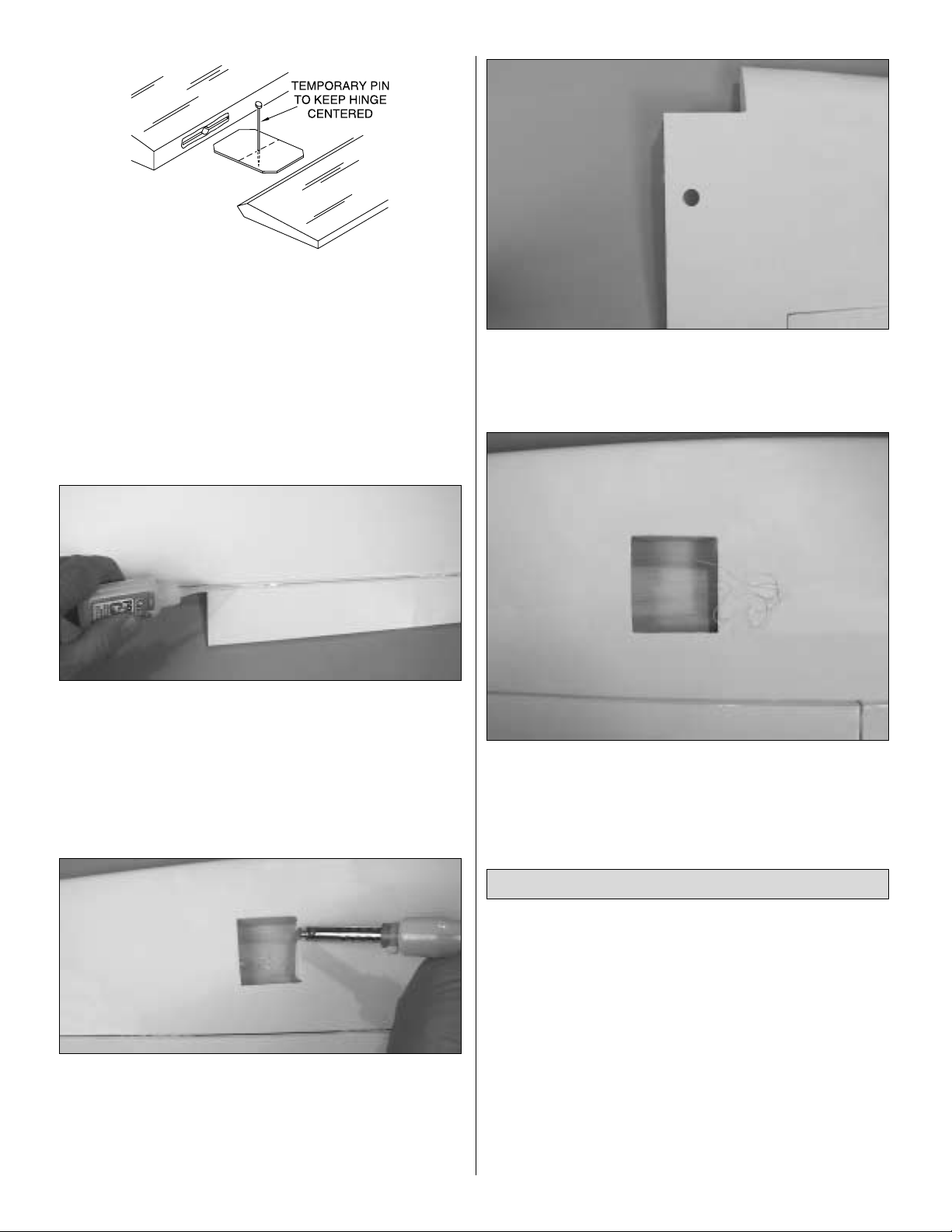
❏❏4.T est fit the ailerons to the wing with the hinges .If the
hinges don’t remain centered, stick a pin through the middle
of the hinge to hold it in position.
❏❏5. Remove any pins you may have inserted into the
hinges. Adjust the aileron so there is a small gap between
the LE of the aileron and the wing.The gap should be small,
just enough to see light through or to slip a piece of paper
through.
❏❏6. Apply six drops of thin CA to the top and bottom of
each hinge. Do not use CA accelerator. After the CA has
fully hardened, test the hinges by pulling on the aileron.
❏❏7. Repeat this procedure for installing the flap using
four CA hinges.Note that the hinge slots on the flap are not
centered as the ailerons are.
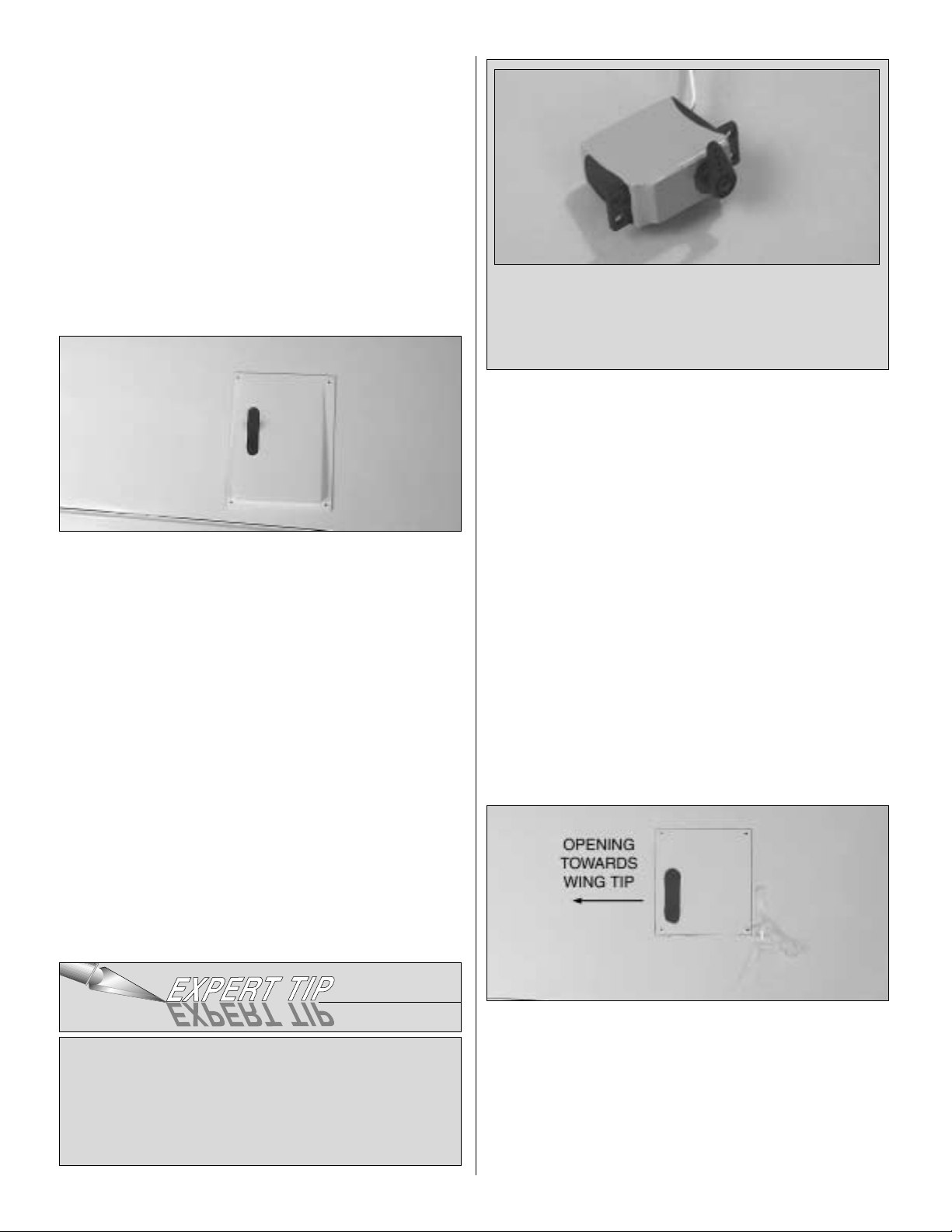
❏❏8. Find the hole for the aileron servo by feeling the
covering on the bottom of the wing. Cut the covering 1/8"
[3mm] inside the opening in the wing for the aileron servo.
Use a trim iron to seal the covering to the inner edges of the
opening. Repeat this same procedure in the opening for the
flap servo.
❏❏9. On the top of the wing, cut the covering away from
the hole at the wing center-section. This hole is for the
aileron and flap servo wires to come through, into the
fuselage.
❏❏10. Locate the string from inside of the aileron ser vo
bay and tape it to the wing. Do not pull the string out of the
wing! Do the same with the string in the flap servo bay.
❏ 11. Repeat steps 1-10 for the left wing panel.
The following steps for installing the servos may be
somewhat different from other servo installations you are
familiar with. You may find it helpful to read through the
servo installation instructions to familiarize yourself with the
process before beginning the installation. Important!
Following these instructions will assure a safe and solid
servo installation.
❏❏1. Installing the ser vos in the wing will require the use
of one 24" [610mm] servo extension for the aileron.
Depending on your brand of servos you may find it
necessary to use one 6" [152mm] servo extension for each
of the flaps.Two Y-harness connectors are required and are
used to allow the aileron servos to plug into one slot in your
Install the Flaps & Aileron Servo
8
Page 9
receiver and for the flaps to be plugged into another slot in
your receiver. You may have a computer radio that allows
you to plug the servos into separate slots and then mix them
together through the radio transmitter. If you choose to mix
them with the radio rather than Y-harnesses, refer to the
instructions for your particular brand of radio.
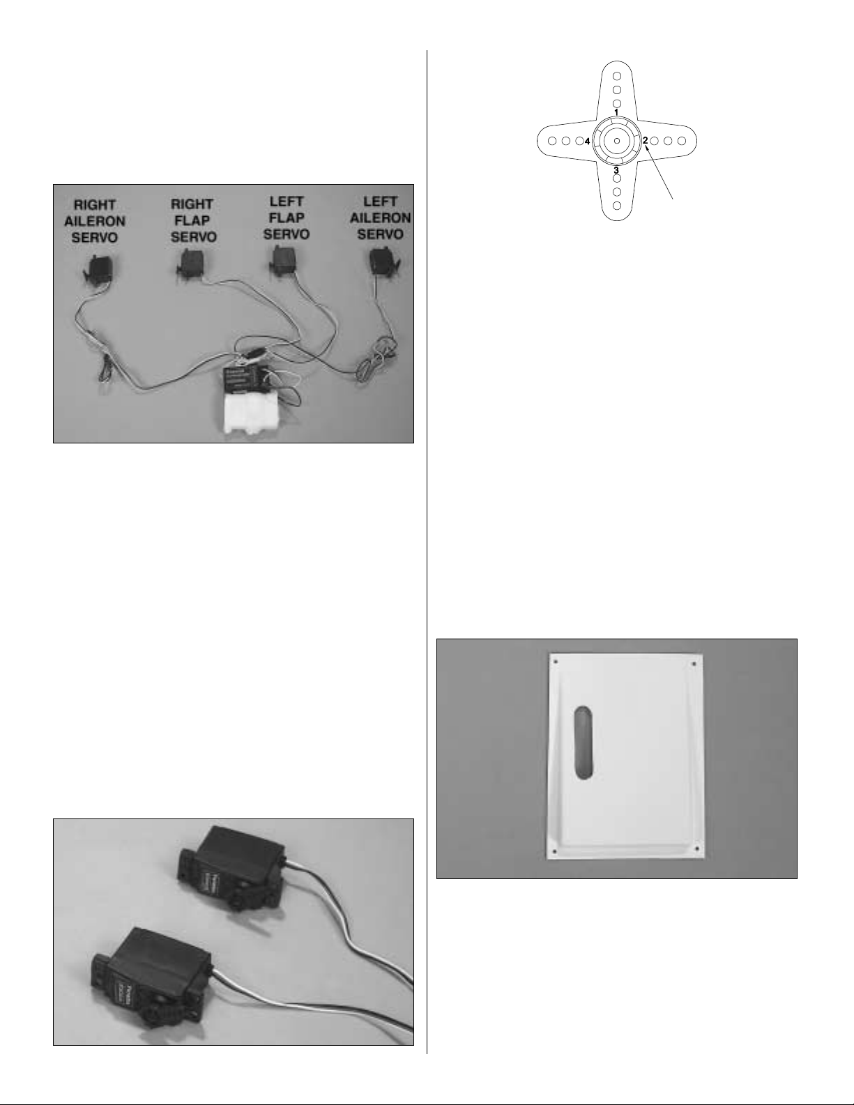
❏❏2. Attach the servo extensions to the aileron and flap
servos. Secure the connectors together using a large piece
of heat shrink tubing, tape or other suitable method. Lay the
servos, receiver and battery on your work bench, placing
the servos just as they will be when installed in the wing.
Remember that you are laying the servos on your bench just
as they will be placed into the bottom of the wing.(Note: You
will not need to install the rubber grommets and eyelets on
the servos for the aileron and flap installation). The servo
arms on the flap servos need to move the same direction.
The aileron servo arms must move opposite one another.
(Note the orientation in the above photograph; remember
you are looking at the bottom of the wing).
❏❏3. Turn your radio system on, allowing the servos to
center.Be sure that all of the radio trims are centered on the
transmitter.
❏❏4. Using the switch or rotary knob that you will be
using to activate the flaps, set the switch to the position that
will bring the flaps into the “up” position (normal flying
mode). Install the ser vo arms onto the servo with the arm
forward. This will allow the servo to push against the flap
control horn to keep the flap retracted.When the flap switch
is in the “flaps down” position (landing mode) the ar m will
rotate in the opposite direction, pulling the flaps down.
Operate the servo using the flap switch to be sure they are
moving the correct way.
Hint: On many brands of servo
arms you will find that each arm has a small number on it.
Each arm has a slightly different position on the servo spline
once it is installed. You will find it helpful for setting up the
flaps if you use two arms with the same number on it (see
above sketch).
❏❏5.Install the servo arms on the aileron servos , making
sure the arms are positioned as shown in the photograph in
step 2. Using your transmitter, operate the aileron servos
making sure that the arms are moving in directions opposite
of one another.When you are satisfied e verything is working
properly, turn off the radio system. Unplug the aileron and
flap servos from the receiver.
❏❏6. Locate the ABS aileron servo cover for the right
wing. Cut out the opening in the cover for the aileron servo
arm. The cut lines for the opening are on the inside of the
cover. Drill a 1/16" hole [1.6mm] in each corner of the
aileron cover.
❏❏7. The side of the aileron servo case that will rest
against the top of the wing inside of the servo bays needs to
be cleaned with rubbing alcohol. Do Not Omit This Step!
This surface must be free of any fuel or oil residue in order
9
Page 10
to assure a good bond between the servo and the servo
tape that will be used for holding the servo to the wing.
❏❏8. Tie the string inside the aileron servo bay to the
aileron servo wire. Pull the ser vo wire out towards the wing
root with the string. Feed the end of the wire through the
hole in the top of the wing center-section.Remove the string
from the servo lead and tape the servo lead to the top of the
wing to prevent it from falling back into the wing.
❏❏9.Place the aileron servo into the servo bay.
Temporarily
place the aileron cover ov er the servo to help locate the final
position for the servo.Remove the cover and mak e a couple
of reference marks inside the servo bay for the servo
location. This will help you relocate the servo when it is
installed in the next step.
❏❏10. Using 6-minute epoxy, permanently glue the servo
in place inside the servo bay, gluing it to the wing skin.
Note:
We understand that some modelers may resist gluing a
servo permanently to the wing. Because of the very thin
airfoil it becomes difficult to make a removable servo
mounting assembly. Fortunately the ser vo required for the
aileron are the standard, inexpensive type and permanently
installing them should not be cost prohibitive.
The Expert
Tip
that follows presents an alternative method of gluing in
the servos.
❏❏11. Place the aileron servo cover over the servo,
making
sure the servo arm is centered in the cut out. Using the
cover as a guide, drill a 1/16" [1.6mm] hole into the wing
skin
through each of the holes in the cover. Remove the
cover.
❏❏12.Thread a #2 x 3/8" [9.5mm] sheet metal screw into
each of the four holes.Remove the screw, then saturate the
holes with thin CA. Enlarge the holes in the cover only with
a 3/32" [2.4mm] drill. Allow the CA to cure and then install
the cover into place over the servo.
❏❏13.Locate the wood flap servo cover f or the right wing.
Cut the covering from the opening for the servo in the cover.
Temporarily place the cover into position with the slot
towards the wing tip. Note: On the left wing, the slot in the
cover is towards the wing root. Drill a 1/16" hole [1.6mm]
through each corner of the aileron cover and through the
hardwood tabs
in the wing. Remove the cover. Drill a 3/32"
[2.4mm]
clearance hole through each of the holes in the
servo cover only!
Should you ever need to remove the servo simply cut the
heat shrink tubing and remove the servo. If you do not
have heat shrink tubing readily av ailab le , y ou can achie v e
similar results by wrapping the servo with electrical tape
and then gluing it in position.
One method for gluing the servo in place while still having
the option to remove it is to wrap 2-1/2" [64mm] heat
shrink tubing around the servo (PARC1625). This heat
shrink is commonly used for making battery packs. After
the servo is tightly encapsulated with the heat shrink
tubing, glue the servo in place in the wing.
10
Page 11
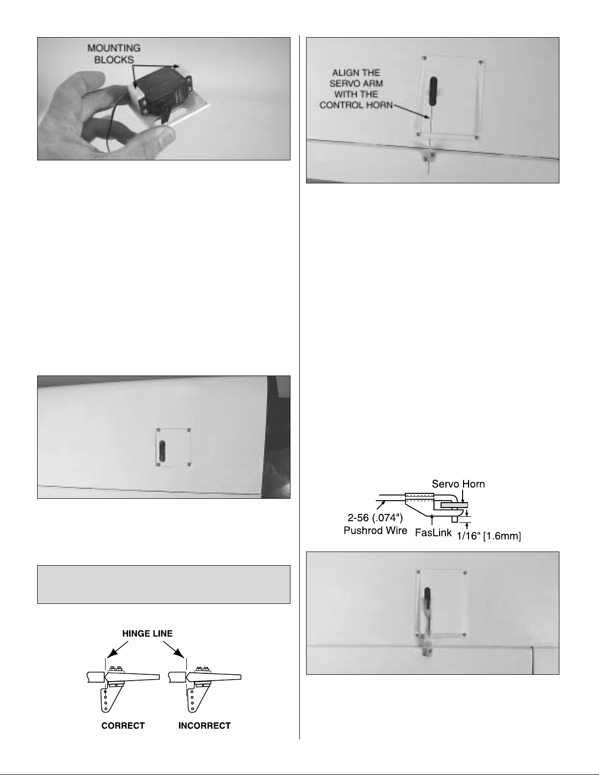
❏❏14. Dr ill 1/16" [1.6mm] holes in two 5/16" x 3/4" x 7/8"
[7.9 x 19.1 x 22.2mm] servo mount blocks and mount the
aileron servo to the blocks using the screws that came with
the servo. Glue the ser vo mount blocks to the inside of the
flap servo cover with 6-minute epoxy.
❏❏15. After the epoxy has hardened, remove the screws
that mount the servos to the blocks. Apply a few drops of
thin CA to the holes and allow to harden.Remount the servo
to the blocks.
❏❏16. Tie the string inside the flap ser vo bay to the flap
servo wire. Pull the servo wire out the root of the wing with
the string. Feed the end of the wire through the hole in the
top of the wing center-section. Remove the string from the
servo wire and tape it to the top of the wing to prevent the
servo wire from falling back into the wing.
❏❏17.Use four #2 x 3/8" [9.5mm] sheet metal screws and
four #2 flat washers to attach the cover to the wing.
❏ 18. Repeat steps 1-17 for the left wing panel.
❏❏1. Position a small nylon control horn on the aileron,
positioning it as shown in the sketch and aligning it with the
servo.Mark the location for the screw holes.Drill through the
marks you made with a 3/32" [2.4mm] drill bit. Mount the
nylon control horn to the aileron by inserting two 2-56 x 5/8"
[2-56 x 16mm] machine screws through the control horn
and into the nylon mounting plate on the top of the aileron.
❏❏2. Locate a .074" x 6" [1.9 x 152mm] pushrod wire
threaded on one end. Thread a nylon clevis onto the
threaded end of the wire 20 turns. Install a silicone clevis
retainer onto the clevis.Then, install the clevis on the aileron
control horn.
❏❏3.Be sure the aileron servo is centered (plug the servo
into the receiver and turn the radio on to re-center it properly
if you are unsure). Enlarge the hole in the ser vo arm with a
Hobbico Servo Horn Drill (or a #48 or 5/64" [2mm] drill bit).
Center the aileron and align the wire pushrod with the hole
in the end of the servo arm. Using a marker, mark the
location
where the wire aligns with the hole in the servo arm. On that
mark make a 90° bend.From the bend measure an
additional
3/8" [9.5mm] and then cut off the excess pushrod wire.
❏❏4. Install the wire into the hole in the servo arm using
a nylon FasLink as shown in the sketch.
❏❏5. Position a small nylon control horn on the flap,
positioning it in the same manner as you did the aileron.
Mark
Install the Flap & Aileron Hardware
& Pushrods
11
Page 12
the location for the screw holes.Dr ill through the mar ks you
made with a 1/16" [1.6mm] drill bit, drilling through the
plywood plate in the bottom of the flap. Do not drill all the
way through the flap. Install the screw, then remove it.
Harden the holes with thin CA.Mount the nylon control horn
to the flap with two #2 x 3/8" [#2 x 9.5mm] sheet metal
screws.
❏❏6. Locate a .074" x 6" [1.9 x 152mm] pushrod wire
threaded on one end. Thread a nylon clevis onto the
threaded end of the wire 20 turns. Install a silicone clevis
retainer onto the clevis. Then, install the clevis to the flap
control horn.
❏❏7.Be sure the flap servo arm is forward, in the position
that will pull the flap into the retracted position. (Plug the
servo into the receiver and turn the radio on to re-position it
properly if you are unsure). Enlarge the hole in the servo
arm with a Hobbico Servo Horn Drill (or a #48 or 5/64"
[2mm] drill bit). Position the flap to the retracted (neutral)
position and align the wire pushrod with the hole in the end
of the servo arm. Using a mar ker, mark the location where
the wire aligns with the hole in the servo arm. On that mark
make a 90° bend.From the bend measure an additional 3/8"
[9.5mm] and then cut off the excess pushrod wire.
❏❏8. Install the wire into the hole in the servo arm using
a nylon FasLink.
❏ 9. Repeat steps 1-8 for the left wing panel.
❏ 1. Locate the two 1/8" [3mm] plywood wing joiners.
Using 6-minute epoxy, glue them together, forming one 1/4"
[6mm] wing joiner.
❏ 2. Test fit the wing joiner into each wing panel, making
sure that it is not too tight. Sand the joiner as needed to get
a good fit.
❏3.Apply 30-minute epoxy to both sides of the wing joiner,
the joiner pocket in both wing panels and to the root rib of
each wing panel. Push the wing panels together and hold
them in place with masking tape. Before the glue cures, set
the wing flat on your bench and measure the dihedral.The
distance from the top of the bench to the bottom of the wing
should be approximately 4-1/8" [105mm].Block the wing tip
up while the glue cures.
Note: Due to production techniques
there may be some variance in the actual dihedral of each
model. Our prototypes flew well with the dihedral anywhere
between 3-7/8" and 4-1/4" [98mm and 108mm].
Minor
differences will not affect the flight characteristics.
❏ 4. Set the wing aside allowing the glue to cure.
❏ 5. Locate two 3/8" x 1-3/4" [9.5mm x45mm] wood
dowels. Apply 6-minute epoxy to the portion of the dowel
that will be inserted into the holes in the leading edge at the
center-section of the wing. Apply epoxy into the holes in the
center-section of the wing. Then, inser t the dowels into the
holes until they stop. Wipe away excess glue from the
dowels and set the wing aside to dry.
❏ 6. Locate the 1/4" [6mm] holes under the covering at the
trailing edge of the wing center-section. Cut the covering
away on both the top and bottom of the wing.
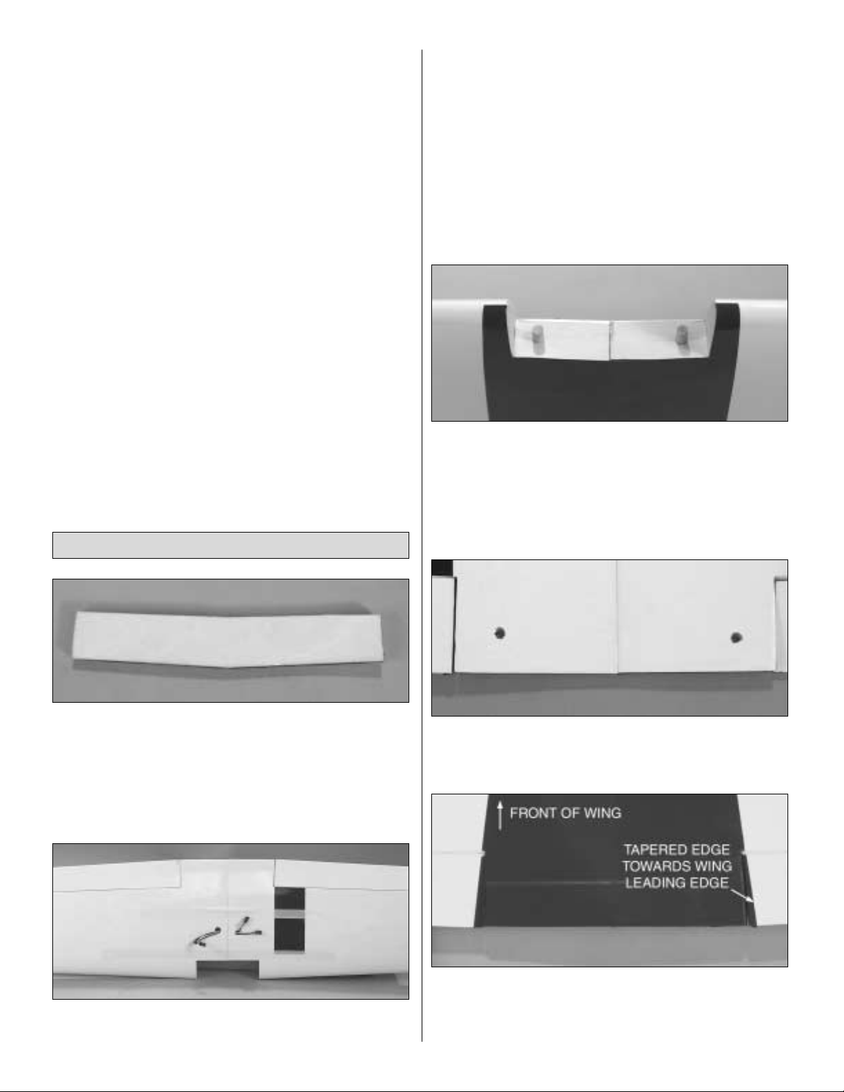
❏7.Lay the wing on your bench with the bottom of the wing
facing you. Locate the hardwood wing hold down plate.
Place the hold down plate in position at the wing trailing
edge with the tapered edge of the plate facing the front of
Join the Wings
12
Page 13

the wing.T r ace the plate onto the wing with a felt-tip pen.Cut
the covering away in the area where the plate will be (see
Expert Tip that follows).
Be careful not to cut into the wood.
This will weaken the structure.
Glue the wing hold down
plate to the wing with 6-minute epoxy.
❏ 8. Once the glue has cured, drill a 1/4" [6mm] hole
through the holes in the top of the wing, drilling through the
wing hold down plate.
❏ 9. On the top and bottom of the wing, cut the covering
away 1/8" [3mm] from the end of the wing tip, being careful
not to cut through the balsa wing skin.
❏ 10. Locate the right wing tip.(When installed on the wing
the curve on the wing tip will be turned up). With 220-grit
sandpaper, roughen the inside of the tip where it will make
contact with the wing and then wipe the area with rubbing
alcohol.
❏❏11. Glue the tip to the wing with 6-minute epoxy.
Repeat this step for the left wing tip.
Set the wing aside and begin the fuselage. You will come
back to the wing and install the landing gear later in the
instructions.
❏ 1. Examine the fiberglass fuselage. At the rear of the
fuselage there are three molded pushrod exits. A 3/16"
[4.8mm] hole needs to be drilled through each of them. You
must follow this pr ocedure! If you try to drill a single 3/16"
[4.8mm] hole the drill
will
tear the fiberglass.Start by drilling
a 1/8" [3mm] hole followed by a 5/32" [4mm] hole and then
a 3/16" [4.8mm] hole. Another method that works very well
is to make the hole with a high-speed rotary tool and a small
grinding bit. This would be the preferred method because
there is almost no likelihood of splitting the fiberglass.
❏ 2. Locate three 24" [610mm] gray outer plastic pushrod
guide tubes. Cut the tubes to a length of 18" [457mm].
Roughen both ends of each tube with 220-grit sandpaper.
Insert the tubes into the holes you drilled, feeding them
through the holes in the rear bulkhead inside of the
fuselage.
❏ 3. Glue each of the tubes into the holes using 6-minute
epoxy. Be sure you have roughened the tubes before gluing
them into position.
Install the Pushrod Tubes &
Fuselage Formers
ASSEMBLE THE FUSELAGE
HOW TO CUT COVERING FROM BALSA
Use a soldering iron to cut the covering. The tip of the
soldering iron doesn’t have to be sharp, but a fine tip does
work best. Allow the iron to heat fully. Use a straightedge
to guide the soldering iron at a rate that will just melt the
covering and not burn into the wood. The hotter the
soldering iron, the faster it must travel to melt a fine cut.
Peel off the covering.
13
Page 14

❏4.Locate the 1/8" [3mm] plywood front and rear
pushrod
support formers. Drill a 3/32" [2.4mm] hole in each cor ner
of the rear former and a 3/32" [2.4mm] hole centered at
each end of the front former.
❏ 5. Place the rear former in position in the rear of the
fuselage opening as shown.The former needs to be placed
flush to the edge of the rear of the wing saddle.
❏ 6.With the former positioned properly, use a felt-tip pen
and mark on the fuselage where the back of the former
rests. Remove the former.
❏ 7. Locate four 1/4" x 3/8" x 3/4" [6mm x 9.5mm x 19mm]
hardwood blocks. These are to be mounted behind the
former.The former will be attached to each of these blocks.
Two blocks need to be glued to the fuselage side.The other
two blocks are glued on top of the wooden block that the
wing bolt blind nuts are mounted to. Sand the inside of the
fiberglass fuselage and clean the area with alcohol where
the blocks are glued to the fuselage. Once the fiberglass
has been prepared, glue the blocks in place with medium
CA glue.
❏8.Put the former back into the fuselage, resting it against
the four hardwood bloc ks .Drill a 1/6" [1.6mm] hole into each
of the blocks drilling through the holes you previously drilled
in the former.Note: You are most likely not going to be able
to use a power drill due to the small area you are working
in. We used a Hobbico®Servo Horn Drill (HCAR0698) but
you can also use a small finger drill, pin vise or in a pinch
you can put a small wheel collar on the end of the drill bit as
a knob to hold and rotate the bit.
❏ 9. Install the pushrod tubes through the former (the two
pushrod tubes that are used for the elevator should be fed
through the two holes that are side-by-side).Do not glue the
tubes to the former.Install the former to the blocks with four
#2 x 3/8" [#2 x 9.5mm] screws and #2 flat washers.
❏ 10. Following the same procedure, install the forward
former. The forward former only requires the use of two
wood blocks, one on each side of the former. Hold the
former in place using two #2 x 3/8" [#2 x 9.5mm] screws and
#2 flat washers.
❏ 11. Once the formers are properly installed, remove the
formers and set them aside. They will be re-installed
permanently when you get to the radio installation.
14
Page 15

IMPORTANT! Steps 1-11 provide instruction for installing a
stab that is removable. Many of you will find this to be a
helpful feature when packing your plane into your car to
head out to the field. You may not have a need for the
removable stab, in which case you can follo w the installation
instructions and never take your stab off. If you choose to,
you can skip steps 2-11 and permanently glue your stab to
the joiners and the fuselage with epoxy. It is suggested you
read through steps 1-11 before making a final decision.
❏❏1.Install the elevators to the stab with three hinges per
elevator, using the same installation method used on the
ailerons on page 7, steps 1-8.
❏❏2. Look closely at the horizontal stab.On one side you
will find a small pin hole.This is the bottom of the stab.Place
a mark on both stab halves indicating the left side/right side.
❏ 3. Locate the 1/4" x 12" [6mm x 305mm] aluminum stab
tube and two 1/4" x 1-1/2" [6mm x 38mm] wood dowels.
Using 6-minute epoxy, glue a dowel into each end of the
stab tube. Set it aside until cured.
❏4.Locate the 5/32" x 6-1/2" [4mm x 165mm] black carbon
fiber anti-rotation pin.Insert it into the front hole in the back
of the fuselage. Center the pin in the fuselage. Then, glue it
in place with a couple of drops of thin CA.
❏ 5. Insert the stab tube into the fuselage, centering the
tube left/right. Once it is centered, mark the tube with a
marker where it meets the fuselage on both sides.
❏ 6. Slide the right side stab onto the tube and the anti-
rotation pin, making sure the root rib of the stab is tight
against the side of the fuselage. Using the reference mark
on the tube on the left side, make sure the tube is still
centered in the fuselage. Dr ill a 1/16" [1.6mm] hole into the
aluminum tube and into the wood dowel inside of the tube.
Do not drill through the opposite side of the tube!
❏7.Remove the stab assembly from the fuselage.Remove
the aluminum tube from the fuse. Thread a #2 x 3/8" [#2 x
9.5mm] sheet metal screw into the hole in the tube.Remove
the screw and apply a drop of thin CA into the hole. Allow
Install the Horizontal Stab, Elevators,
Rudder & Pushrods
15
Page 16

the CA to cure.Then, re-insert the screw and again remove
the screw. Run your finger over the hole. You will probably
notice a small burr or bump on the metal. Remove the burr
using 220-grit sandpaper.
❏ 8. Inser t the tube back into the right side stab, aligning
the hole in the stab with the hole in the stab tube.
Hint: A
T-pin will be helpful in aligning the holes.
Attach the stab to
the tube by installing the #2 x 3/8" [#2 x 9.5mm] sheet metal
screw through the hole in the bottom of the stab and into the
tube.Be sure to tighten the screw until it is firmly resting
against
the plywood that is underneath the balsa skin of the stab.
❏ 9. Insert the tube back into the fuselage with the right
side stab attached to the tube. Slide the left side stab onto
the tube, making sure the root rib of the stab is tight against
the side of the fuselage. When properly installed on the
tube, drill a 1/16" [1.6mm] hole into the aluminum tube and
into the wood dowel inside of the tube.
❏ 10. Remove the left side stab from the tube. Install a #2
x 3/8" [#2 x 9.5mm] sheet metal screw into the hole in the
tube.Remove the screw and apply a drop of thin CA into the
hole. Allow the CA to cure, then re-insert and again remove
the screw. Run your finger over the hole, feeling for a burr.
Remove any burr from the tube.
❏ 11. Re-install the stab to the tube by inser ting the #2 x
3/8" [#2 x 9.5mm] sheet metal screw through the hole in the
bottom of the stab and into the tube. Be sure to tighten the
screw until it is firmly resting against the plywood that is
underneath the balsa skin of the stab.
❏ 12. Locate two 36" [914mm] wire pushrods threaded on
one end and cut them to a length of 27" [685mm], making
sure you cut the wire off at the unthreaded end of the
pushrod wire. Insert them into the pushrod tubes that are
used for the elevator control. (These are the tubes in the
white molded blisters on the
fuselage.) The threaded end of
the pushrod should be
towards the elevator.
❏13.Position a large nylon contr ol horn on the right
elevator,
positioning it as shown in the sketch and aligning it with the
pushrod. Mark the location for the screw holes. Drill through
the marks you made with a 3/32" [2.4mm] drill bit.Mount the
nylon control horn to the elevator by inserting two 2-56 x
3/4" [2-56 x 19mm] socket head cap screws through the
control horn and into the nylon mounting plate on the top of
the elevator.
❏ 14. Thread a nylon clevis onto the threaded end of the
wire 20 turns.Install a silicone clevis retainer onto the clevis.
Then, install the clevis on the elevator control horn.
❏ 15. Repeat the process for installing the control horn on
the left elevator.
❏ 16. Install the rudder with three CA hinge strips following
the same technique used for the other control surfaces.
REMOVING THE STAB FOR TRANSPORTATION AND
STORAGE
When you find the need to remove your stab from the
fuselage, you will find that it is much simpler to re-install
the stab if you only remove the stab from one side of the
tube and leave the remaining stab attached to the tube.
By doing this you will not have any difficulty aligning the
hole in the stab with the hole in the tube when reinstalling
the stab half. If you are consistent in removing the same
side each time, you will minimize wear to the holes in the
tube.If you plan to remove the tube completely from both
stab halves, it is a good idea to mark the right and left
side of the aluminum tube to be sure everything aligns
properly when put back together.
If at any time you find that a screw is getting loose in the
hole, add a small drop of thin CA to the hole to add more
material into the hole. Our prototype did not experience
any loosening of the screw from normal flying but you
should check the screws every few flights to be sure they
are tight.
16
Page 17

❏17. Position a large nylon control horn on the left side of
the rudder, over the plywood plate located under the
covering, aligning it with the pushrod. Use a T-pin to locate
exactly where the plywood plate is on the left side of the
rudder. Mark the location for the screw holes. Drill through
the marks you made with a 1/16" [1.6mm] drill bit, drilling
only through the plywood plate on the left side of the rudder.
Do not drill all the way through the rudder! Thread two
#2 x 3/8" [#2 x 9.5mm] sheet metal screws into the holes
you drilled.Remove the screws and apply a couple of drops
of thin CA into the holes to harden them. Mount the nylon
control horn to the rudder with two #2 x 3/8" [#2 x 9.5mm]
sheet metal screws.
❏ 18. Cut another 36" [914mm] wire pushrod threaded on
one end to a length of 28" [711mm], making sure you cut the
wire off at the un-threaded end of the pushrod wire. Inser t it
into the pushrod tube for the rudder.The threaded end of the
pushrod should be towards the rudder.Thread a nylon cle vis
onto the threaded end of the wire 20 turns. Install a silicone
clevis retainer onto the clevis and then install the clevis on
the rudder control horn.
The following instructions are for installing an O.S.®.61
engine (OSMG05610) with the Top Flite in cowl muffler
(TOPQ7917) and Top Flite muffler header (TOPQ7920).
This combination of engine and muffler allowed us to
completely enclose the engine in the cowl. Because of this
enclosed engine installation, some engine baffling is
necessary and is explained once you proceed to installing
the cowl.The engine mount and installation instructions for
the engine mount will work for most .61-.75 two-stroke and
.91 four-stroke engines.If you choose to install your engine
with a standard muffler system you will need to make
different cut outs in the cowl than we will be showing in this
manual. Now is the time to deter mine the exact engine and
muffler you will be using.
❏ 1. Locate the engine mount template located on page 39
of this manual. Cut the template from the manual.
❏2.Molded into the firewall are lines that are for
referencing
the location of the engine mount template. Using a felt-tip
pen, draw through the lines extending them further out to
each side of the firewall.
❏ 3. Tape the engine mount patter n to the firewall, aligning
the pattern on the lines you have drawn on the firewall. Drill
a 3/32 [2.4mm] pilot hole through each of the marks in the
corners of the pattern. Then drill through the pilot holes with
a 7/32" [5.6mm] drill bit.
❏4. Remove the template and install four 8-32 blind nuts on
the backside of the firewall.This is easily done if you insert
an 8-32 bolt into a #8 washer. Insert the bolt and washer
through the hole.Reach into the fuselage with the blind nut,
inserting it on the bolt. Tighten the bolt against the firewall,
pulling the blind nut into place.You should have little trouble
reaching into the fuselage to insert the blind nut. If you
should have difficulty you ma y find it easier if y ou remov e
the
forward former you installed earlier. Remember to re-
install it
after the blind nuts are in place.
Install the Engine
INSTALL THE ENGINE & MUFFLER
17
Page 18

❏ 5. Locate the left and right halves of the engine mount.
Remove the tabs.
❏ 6. Mount the engine mount to the fuselage. We will be
installing the engine in a side-mounted configuration. Install
the mount with four 8-32 x1" [8-32 x 25mm] sock et head cap
screws, four #8 lock washers and four #8 flat washers.
Leave the bolts slightly loose.
❏ 7. Position your engine onto the engine mount. With the
engine resting on the engine mount rails, center the engine
and engine mount.Then, tighten the engine mounting bolts.
With your engine still resting on the rails, position the engine
so that the distance from the firewall to the front of the
engine thrust washer is 5-7/8" [150mm]. With the engine
properly positioned, resting on the engine mount, slide the
cowl onto the fuselage to be sure the engine is extending
out of the cowl far enough.If you plan to use a spinner other
than the one supplied with the kit, make sure you have
adequate clearance for your spinner.
❏ 8. Using the engine as a guide, mark the four holes for
the engine bolts on the engine mount. This is easily
accomplished with a Great Planes Dead Center™Tool
(GPMR8130).Install the engine onto the engine mount. Drill
four #36 (7/64") [2.8mm] holes in the mount. Then, use a
6-32 tap to thread the holes.
❏ 9. Use four 6-32 x 1" [6-32 x 25mm] socket head cap
screws, four #6 lock washers and four #6 flat washers to
install the engine onto the mount.
As previously stated, the O.S. .61 and the Top Flite in cowl
muffler (TOPQ7917) and Top Flite muffler header
(TOPQ7920) work well to give a completely cowled
installation of the engine and muffler. For everything to fit
you will need to make the following modifications to the
muffler and header.
❏1.Remove 1/4" [6mm] from the end of the muffler header
and the muffler inlet. This can be done with a hacksaw,
rotary cutting wheel or grinder.
❏ 2. Install the washer and pressure tap into the muffler.
Use thread locking compound on the pressure tap before
threading it into the muffler.
Join the Muffler
18
Page 19

❏ 3. Install the header onto the engine. Align the muffler
inlet with the exhaust outlet on the header .This is the proper
placement for the muffler. Mark the firewall where the
muffler
mounting bolts will be installed to the firewall. Note: You
want to have a gap betw een the header and the m uffler.You
do not want any metal to metal contact that could vibrate
and cause noise that may interfere with your radio system.
❏ 4. Drill a 5/64" [2mm] hole through the mar ks you made
on the firewall.Install the screws, then remove them.Harden
the holes with thin CA. Using the screws and rubber pads
included with the muffler, insert a rubber pad behind each
mounting foot of the muffler (the rubber foot insulates the
muffler from the firewall). Then, install the muffler to the
firewall.
❏5.Cut the rubber coupler to fit tightly between the header
and the muffler.Remove the header and install the coupler
over the muffler. Insert the header into the coupler and reattach the header to the engine using a small amount of
thread locking compound.
The following steps cover installation of the nose wheel as
well as an air outlet. The air outlet is required for proper
cooling with the Top Flite muffler. If you are installing a
standard muffler and have large cut outs in the cowl for the
muffler you probably can skip installation of the air outlet.
However, the extra air outlet cannot hurt for any engine
installation.
❏1.Locate the fiberglass exhaust air panel.Place a piece
of masking tape down the center of the panel.Measure and
locate the exact center of the panel and draw a centerline
on the tape.
❏ 2. Align the center of the panel with the center of the
fuselage. Place masking tape on the fuselage under the
edges of the panel. Re-center the panel if necessar y.Then,
trace the shape of the panel onto the fuselage.
❏ 3. Measure inside the outline 1/4" [6mm] from the sides
of the panel and 1/4" [6mm] from the rear edge of the panel.
Draw this onto the tape with a marker.
Note: The next step is done fairly easily using a high
speed rotary tool such as a Dremel tool. This combined
with a reinforced fiberglass cut-off wheel will make the
next step pretty easy.Without one it is going to be a pretty
laborious job. If you do not own a high-speed rotary tool
we suggest you purchase one or borrow one from
another modeler. Most modelers probably have at least
one of these in their tool collection.
Install the Nose Wheel
19
Page 20

❏ 4. On the inside lines that you have drawn, cut that
portion of the fuselage and firewall away. After you have
removed it, test fit the exhaust air panel into the opening.
Because the exhaust air panel is a fiberglass lay up, there
may be some slight variations in manufacturing. Trim the
opening to fit your exhaust air panel.
❏ 5. When you are satisfied with the fit, lightly sand the
backside of the exhaust air panel where it will contact the
fuselage and firewall. Lightly sand the part of the fuselage
where the panel will contact the fuselage. Wipe the areas
you have sanded with rubbing alcohol.
Failure to properly
prepare these parts will create a poor bond between the
panel and the fuselage.
Using 6-minute epoxy, glue the
exhaust air panel into place on the fuselage, holding it in
place with masking tape while the epoxy is curing. Clean
any excess epoxy with a rag dampened with alcohol.
❏ 6. After the glue is completely cured, remove the tape.
With the panel in place you will see that it will conflict with
the cowl installation. Sand the corners of the panel so they
match the step in the fuselage that the cowl rests against.
This is easily done with the high speed rotary tool and the
reinforced fiberglass cut off wheel.
❏ 7. Using a 5/32" [4mm] drill bit, drill through the hole
located in the engine mount.
❏ 8. Locate the 3/16" x 3/4" x 1-1/4" [4.8mm x 19mm x
32mm] plywood nose gear mounting block. Temporarily
locate it on the fuselage, centered above the hole in the
engine mount.The bottom of the wood block should be ev en
with the edge of the air exhaust panel.Mark the location on
the firewall. Using 220-grit sandpaper, roughen the area on
the fuselage where it will be attached. Then, glue it to the
firewall with 6-minute epoxy.
❏9. Locate the nylon nose gear bearing. Position it on the
wood block so the bottom of the nylon nose gear bearing is
flush with the bottom of the wood block.Mark the location of
the mounting holes.Then, drill two 5/64" [2mm] holes on the
marks in the wood block. Slide the nose gear wire into the
nose gear bearing and into the hole in the engine mount.
Harden the holes with thin CA.Mount the nose gear bearing
to the wood block with two #4 x 5/8" [#4 x 15.9mm] sheet
metal screws.
❏ 10. Insert a 5/32" [4mm] wheel collar into the nylon nose
gear steering arm and a 6-32 x 1/4" [6-32 x 6mm] socket
20
Page 21

head cap screw into the arm and wheel collar. Slide the
metal nose gear wire into the nylon nose gear bearing,
nose gear steering arm and engine mount. The coil of the
nose gear wire should rest on the nylon nose gear bearing.
Tighten the set screw against the flat spot in the nose
gear wire.
❏11. Cut one of the 24" [610mm] gray outer pushrod tubes
in half, making two 12" [305mm] tubes.Roughen one end of
the outer pushrod tube with sandpaper. Inser t the end you
did not roughen into the hole in the firewall adjacent to the
nose gear steering arm (see the photo at step 13). Apply
glue to the roughened end of the outer pushrod tube and
insert it into the firewall, allowing the end of the tube to
extend approximately 1/4" [6mm] be y ond the fire wall.Do the
same with the second tube, inserting it into the hole in the
firewall for the throttle pushrod and through the hole in the
former, behind the firewall.
❏ 12. Locate a .074 x 36" [1.9 x 450mm] pushrod wire.
From the unthreaded end of the wire, cut a 15" [381mm]
long, unthreaded pushrod wire. Insert the pushrod into the
outer pushrod tube for the nose gear steering.
❏ 13. Locate the brass screw-lock pushrod connector,
4-40 x 1/8" [4-40 x 3mm] socket head cap screw and nylon
retainer. Install it on the steering arm as shown in the
sketch, tightening the set screw to the wire pushrod.Be sure
to leave approximately 3/8" [9.5mm] of wire extending
through the screw-lock pushrod connector to allow for
adjustment to the steering.
❏ 14. From the remainder of the 36" wire you cut, thread a
nylon clevis onto the threaded end of the wire 20 turns.
Install a silicone clevis retainer onto the clevis. Then, install
the pushrod into the outer pushrod tube for the throttle.
Install the clevis on the carburetor arm. Depending on the
exact location of your carburetor, you may need to make a
small bend in the wire to get free movement of the throttle
and pushrod.
❏ 15. Carefully cut out the left and r ight halves of the ABS
nose gear fairing.
❏ 16.The next two steps are going to require you to work
rather quickly so be sure you have 6-minute epoxy,
microballoon filler and a small piece of waxed paper ready.
Mix 1/2 ounce of 6-minute epoxy. Add some microballoon
filler.Spread a small amount along the inside edges of both
the left and right fairing. Move quickly and don’t worry if it is
not too uniform.We are not filling up the fairing;only building
up the edges as shown in the photo at step 18.
21
Page 22

❏ 17. Turn the fairings over, placing them on a piece of
waxed paper. Allow the glue to cure.
❏ 18. Once the glue cures, remove the fairings from the
waxed paper. The glue will have formed a nice edge all
around the fairings. This is going to provide a surface for
gluing the two halves together.
❏ 19. Use a coarse 100-grit sandpaper to roughen up the
plating on the landing gear wire where the fairings are to fit.
Wipe the wire with alcohol.
❏ 20. Position the nose gear wire as if you are taxiing the
airplane straight on the runway. Position one of the fairings
onto the wire so that it is also aligned straight ahead. Tack
glue the fairing to the wire with a small amount of CA.
❏ 21. Mix another small amount of 6-minute epoxy and
microballoon filler.Coat the area around the fairing that is in
close contact with the wire so that the fairing is securely
glued to the wire. Allow the glue to cure. Before the glue
dries you can clean any excess glue from the outside of the
fairings with rubbing alcohol.
❏ 22. Glue the two halves of the fairing together. This can
be done with either CA or 6-minute epoxy.
❏23.Locate the nose wheel pant (the nose wheel pant has
a small groove molded into one side) and two 1/8" x 3/8" x
3/4" [3mm x 9.5mm x 19mm] plywood plates.
❏ 24. Drill a 5/32" [4mm] hole at the bottom of the molded
groove in the wheel pant for the axle to pass through.
22
Page 23

❏ 25. Roughen the area in the wheel pant where the
plywood blocks are to be mounted. Wipe the area with
rubbing alcohol. After the alcohol has dr ied, glue the blocks
into the wheel pants along side the groove for the nose
gear wire.
❏ 26. Lay the wheel pant on your workbench with the
grooved side facing you. Locate the nylon landing gear
strap and position it on the wheel pant, making sure it lays
over the groove in the pant and that the holes for mounting
it are aligned over the blocks inside the pant.When you are
sure it is properly positioned, mark the mounting hole
locations on the wheel pant. Drill a 1/16" [1.6mm] hole
through each of these marks.
❏ 27. File a flat spot on the bottom of the end of the nose
gear wire. Partially slide the wheel pant onto the landing
gear wire. Slide a #6 flat washer over the landing gear wire
followed by the wheel. Inser t a 6-32 set screw into a 5/32"
[4mm] wheel collar (use a bit of thread locking compound for
this).Then, install the wheel collar onto the end of the nose
gear wire to hold the wheel to the nose gear wire. Use two
#2 x 3/8" [#2 x 9.5mm] sheet metal screws to attach the
landing gear strap to the wheel pant and nose gear wire.
❏ 1. At the wing center-section on the bottom of the wing
locate the cut outs for the landing gear. Cut the covering
away, revealing the plywood mounting plates.Seal the
edges
of the covering with your covering iron. Apply thin CA to the
wood and allow it to cure.This will fuelproof the wood.
❏ 2. Place both landing gears in place on the plywood
plates. Drill a 5/64" [2mm] hole through each of the
mounting holes in the landing gear. Thread a screw into
each hole, and then remove the screws. Harden the holes
with thin CA.Then, mount the gear to the plate with four #4
x 1/2" [#4 x 13mm] sheet metal screws.
❏3. Locate two bolt-on landing gear axles.The axles
need
to be shortened. Cut each axle to a length of 1-1/4"
[32mm].
❏ 4. Bolt an axle to each landing gear with a 5/16"-24
[8mm-24] axle nut.
❏❏5. Place a piece of masking tape centered on the left
side of a wheel pant.This pant will be mounted to the right
landing gear.
(Note: When doing this for the wheel pant on
the left landing gear, the hole will be made on the right side
of the wheel pant).
Measure the opening in the wheel pant
to find the exact center. Draw a line on the masking tape
indicating the center of the wheel pant.Measure up from the
bottom of the wheel pant 1/2" [13mm] and mark another
line. Drill a 5/32" [4mm] hole at the intersection of the lines
through the side of the pant. Do not drill through the outside
of the pant.
Install the Main Landing Gear
23
Page 24

❏❏6. Draw a 1/2" [13mm] circle onto the wheel pant
centered on the hole you have drilled. Use a high-speed
rotary tool and a small grinding wheel to open the hole to
1/2" [13mm]. If you have to use a drill, drill a series of
progressively larger holes until you get up to 1/2" [13mm].If
you try to drill a 1/2" [13mm] hole without getting
progressively
larger the bit
will
tear the fiberglass.
❏❏7. Locate one of the 1-1/8" x 1-1/8" x 1/8" [28mm x
28mm x 3mm] plywood landing gear mounting plates.
Mark the plate as shown in the sketch. Drill a 1/2" [13mm]
hole in the plywood plate.
❏❏8. Roughen the inside of the wheel pant with 220-grit
sandpaper around the hole you have made. Clean the area
with rubbing alcohol. Glue the plywood plate to the inside of
the wheel pant, aligning the 1/2" [13mm] holes over each
other.
❏❏9. This step will probably require the help of another
person.Temporarily install the wing onto the fuselage. Put a
wheel on the left landing gear axle.Put the wheel and wheel
pant on the right landing gear axle. Align the pant with the
nose gear wheel pant. (This is where the other person can
help). When they are aligned with each other, press a T-pin
through one of the mounting holes in the landing gear,
making a mark on the wheel pant. Remove the wheel pant
from the axle. Drill a 1/16" [1.6mm] hole through the mar k
the pin left on the wheel pant. Put the wheel and the wheel
pant back onto the axle. Insert a #2 x 3/8" [#2 x 9.5mm]
sheet metal screw through the mounting hole in the landing
gear and insert it into the wheel pant. Stand back and look
at the wheel pant again. If you are satisfied with the
alignment, drill another 1/16" [1.6mm] hole through the
other mounting hole in the landing gear and wheel pant.
Remove the screws and harden the holes with thin CA.
Insert #2 x 3/8" [#2 x 9.5mm] sheet metal screws through
the mounting holes in the landing gear, installing them into
the wheel pant.
❏❏10. Remove the wheel and the wheel pant from the
axle.Locate two 5/32" [4mm] wheel collars and two 6-32 set
screws. Apply a small amount of thread locking compound
to the set screws. Insert the set screws into the wheel
collars. Slide the wheel pant par tially onto the axle followed
by a wheel collar , the wheel and another wheel collar .Attach
the wheel pant onto the landing gear. Then, center the
wheel using the wheel collars. Once centered, tighten the
set screws in the wheel collar to keep the wheel centered in
the wheel pant.
❏ 11. Repeat steps 5-10 for the remaining wheel pant.
Important!
When repeating step 5, make sure you drill the
hole on the opposite side of the wheel pant than you did for
the previous wheel pant.
24
Page 25

❏ 1. Remove the forward and rear former that you installed
into place during the fuselage construction.
❏ 2. Assemble the fuel tank as shown in the sketch. When
tightening the center screw be sure not to overtighten it.You
just want it snug enough to pull the rubber stopper tight
against the tank.
❏ 3. Install silicone fuel tubing (not included in the kit) onto
the aluminum tubes from the fuel tank.The line with the fuel
clunk will feed to the fuel inlet at the needle valve and the
other will attach to the pressure tap on the muffler. For our
installation we chose to use an external fill valve. If you
choose to do this as well, follow the instructions with the fuel
valve.Should you choose not to install a fuel filler valve, y ou
can fill the fuel tank by removing the fuel line to the
carburetor and filling through it. However, depending how
you cut out the cowling to accommodate the engine, the
cowling may make it difficult to access the carburetor.You
can also install a third line to the tank and use it for filling the
tank. The method you use is your choice but make your
decision before moving onto the installation of the fuel tank.
❏ 4. Hold the tank in place inside the fuselage by wrapping
two #64 rubber bands around the tank, attaching the bands
to the tabs in the plywood former that supports the tank.
❏ 1. Locate the two die-cut 1/8" [3mm] plywood
receiver/battery trays. Glue them together forming one
1/4" [6mm] tray.
❏ 2. Draw a line down the center of the tray.
❏ 3. Place masking tape on the rear portion of the wing
saddle where the wing bolt holes are located. Draw
reference marks as shown in the photograph. Drill a 1/8"
[3mm] hole through the marks you made on both sides of
the centerline. Be sure that you keep the drill per pendicular
to the surface you drill through.
❏ 4. Insert the receiver/battery tray into the fuselage,
aligning the centerline of the tray with the centerline of the
INSTALL THE RADIO SYSTEM
Install the Fuel Tank
25
Page 26

fuselage.The tray will rest between the wing bolt mounting
blocks and on the hardwood rail between the blocks. Place
the tray so that it is positioned 1/4" [6mm] behind the wing
saddle as shown in the photograph. (It is necessary to
position it here so there is room to re-install the rear former).
Once it is properly positioned, drill a 1/8" [3mm] hole
through the two holes you previously drilled in the wing
saddle and through the tray.
Important: When drilling the
holes through the tray, be sure the tray is being held firmly
against the hardwood rail in the fuselage and that the drill
remains perpendicular to the drilling surface.
❏ 5. Remove the tray and insert a 4-40 blind nut into each
of the holes in the tray. Apply a small amount of CA to the
blind nut to help secure it to the wood.Be careful not to get
any glue into the threads!
❏6. Locate two 4-40 x 5/8" [4-40 x 16mm] phillips pan head
screws. Using a small grinding bit and a high-speed rotary
tool, grind away enough of the fiberglass around the holes
you drilled in the wing saddle to allow the head of the
screws to sit down flush with the top of the saddle.
Countersinking the heads of the screws allows the wing to
be put in place in the wing saddle without the heads of the
screws protruding into the wing.
❏ 7. Set the receiver/battery tray aside for now. You will
install it later.
❏8. Locate the two plywood servo trays.Glue them
together
forming one 1/4" [6mm] servo tray. Drill a 1/8" [3mm] hole
through each corner of the tray.
❏9. If you did not remove the front and rear formers as you
were instructed earlier in this manual, remove them now.
❏10. Insert the tray into the fuselage .The tray needs to rest
on the hardwood rails inside of the fuselage.Getting the tray
on top of the rails is a bit tricky. Insert the tray into the
fuselage, sliding it forward into the front of the fuselage,
almost up to the fuel tank. Raise the tray high enough to sit
on top of the rails. Then, slide the tray towards the back of
the fuselage, resting the tray on top of the hardwood rail.
Position the tra y in the fuselage as sho wn in the photograph.
Through the holes previously drilled in the tray, drill a 1/16"
[1.6mm] hole into the hardwood rails. Thread a #2 x 1/2"
[13mm] screw into the holes in the rail, remove the screw
and put a drop of thin CA into the hole to harden it.Once the
glue has cured, install the tray to the rails using four #2 x
1/2" [13mm] sheet metal screws and four #2 washers. Reinstall the front and rear formers into position, inserting the
pushrod tubes into the holes in the formers.
26
Page 27

❏11. Using the hardware included with your servos, mount
the throttle, elevator and rudder servos onto the tray,
positioning them as shown.
❏12.Wrap the battery and receiver in 1/4" [6mm] foam (not
included). Install your battery and receiver onto the
receiver/battery tray as shown (the battery should be at the
aft end of the tray). Use two #64 rubber bands on both the
battery and the receiver to hold them securely to the tray.
❏ 13. Install your radio switch and charge jack to the
fuselage. We used the Great Planes Switch and Charging
Jack Mounting Set (GPMM1000).We mounted it on the left
side of the fuselage behind the servo tray.
❏ 14. Temporarily set the receiver/battery tray onto the
fuselage. Plug the switch into the battery and receiver. Plug
the servos into the receiver. Turn the transmitter and
receiver on, centering the servos.Place the servo arms onto
the servos as shown in the photograph at step 13.Once the
servos are centered, you can unplug everything and set the
receiver/battery tray to the side or you can leave things
plugged in and do the following steps. If you leave things
connected you may wish to use masking tape to hold the
receiver/battery tray to the fuselage while you are working.
Refer to this photo when connecting the pushrods in
the following steps.
❏ 15. Pull the throttle pushrod wire as far aft as it will go.
Align the throttle pushrod wire with the hole in the end of the
throttle servo arm. Using a marker, mark the location where
the wire aligns with the outside hole in the servo arm. On
that mark make a 90° bend.From the bend measure up 3/8"
[9.5mm] then cut off the excess pushrod wire.
❏ 16. Install the wire into the hole in the servo arm using a
nylon FasLink as shown in the sketch.
❏ 17. Center the rudder and the nose gear. Install the
pushrod wires to a double servo arm using the same
procedure you used on the throttle.Use the outside hole for
the rudder and the second hole in from the end for the
nose wheel.
❏ 18. Center the elevators, then align one of the elevator
pushrods with the hole you are using in the elevator servo
arm. Mark the wire where it meets the hole in the servo arm.
27
Page 28

Slip two 5/32" [4mm] wheel collars onto the pushrod. Bend
the pushrod 90 degrees up at the mark. From the bend
measure up 3/8" [9.5mm].Then, cut off the excess pushrod
wire. Install the wire into the hole in the servo arm using a
nylon FasLink.
❏ 19. Re-center the other elevator. Bend the pushrod as
shown above to mate it with the first pushrod.Place the two
wheel collars as shown; put a drop of Great Planes Pro
Threadlocker™in the wheel collar screw hole and tighten the
wheel collar to the wires with a 6-32 x 1/4" [6-32 x 6mm]
socket head cap screw in each wheel collar.
You should now have all of the servo installation complete.
This leaves only the installation of the receiver/battery tray
into the fuselage.With all of the room in the fuselage you are
probably wondering why we don’t have the battery and
receiver mounted on a tray with the servos.The battery and
receiver need to be mounted where we have them in order
to achieve the proper balance without having to add weight
to the tail.This airplane has very clean lines and there is no
place we could have easily added tail weight without having
to stick lead to the tail or the fuselage. Though it is a bit
inconvenient, this installation utilizing a removable rear
former allows you to balance the plane without added
weight. Also, the removable front former allows access for
servicing the fuel tank.
❏ 1. If the servos are not still connected to the receiver,
reconnect them. Plug the battery into the switch. Slide a
piece of heat shrink tubing over the connection or tape the
connections together to prevent them from coming loose in
flight. In addition to your servo connections, plug two 12"
extensions into the proper channels on your receiver for the
aileron and flaps. Mark the end of each extension for easy
identification of the flap and aileron.
❏ 2. Install the receiver/battery tray using the two 4-40 x
5/8" [4-40 x 16mm] phillips pan head screws.In order to do
this you will probably need to disconnect the pushrods and
possibly remove the screws from the rear former. It really
depends on how large your hands are.Again, we
understand
this is a bit inconvenient but once installed, you should not
have to remove the tray very often.
❏ 1. Here is a suggested method for installing the receiver
antenna. Other methods may also be acceptable. Drill a
5/32" [4mm] hole in the bottom of the fuselage.Be sure that
this hole does not interfere with the location of the receiver
tray. Insert a 3/4" length of fuel tubing into the hole. This will
protect the wire from being cut by the edge of the fiberglass.
❏ 2. With a leftover servo arm, make a strain relief for the
antenna as shown. Install one ar m onto the antenna wire,
sliding it onto the wire to within a few inches of the receiver.
Insert the antenna through the hole / fuel tubing in the
fuselage. Guiding the wire to the aft of the fuselage, install
the other arm onto the end of the wire as shown.
❏ 3. The rubber band needs to be placed over an
attachment point at the end of the fuselage. We drilled a
5/64" [2mm] hole at the rear of the fuselage, tapped the hole
with a 2-56 tap and made a hook from a small length of
2-56 threaded rod.You might also consider installing a T-pin
in the bottom of the rudder or you can tape the rubber band
to the bottom of the fuselage.
Receiver Antenna Routing
Install the Receiver & Battery
28
Page 29

❏ 1.Test fit the cowl onto the fuselage.You will see that a
cut out needs to be made in the cowl to accommodate the
nose gear.Mark the location for the clearance slot.Then, cut
an opening in the cowl approximately 1/2" x 1" [13mm x
25mm].
❏ 2. Locate the 1/8" [3mm] plywood baffle. This baffle has
been made to fit the O.S. .61 two-stroke engine. As stated
during the engine installation, this baffle is only required if
you are using the in-cowl muffler system from Top Flite.
Because of the tight engine and muffler installation it is
important that proper air flow is achieved over the head of
the engine. If you are using a different engine and adapting
it to the Top Flite in cowl muffler, you may have to change
the inside shape of the baffle. If you have chosen to use a
standard muffler or are installing a four-stroke engine, you
will have to make cut outs in the cowl to allow the head of
the engine to clear the cowl or for muffler clearance. In this
case there is no need for the baffle.If you are not using the
in-cowl muffler system, skip ahead to step 6.
❏ 3. The photograph shows the position of the baffle over
the engine when it is installed inside of the cowl.If you have
any part of your engine or throttle linkage that conflicts with
the baffle, make those adjustments now.
❏ 4. Place the baffle into the cowl. The baffle should be
approximately 3-3/8" [85mm] from the trailing edge of the
cowl. Roughen the inside of the cowl with 220-grit
sandpaper where the baffle makes contact with the cowl.
Clean the area with alcohol. Re-position the baffle. Use a
couple of small drops of CA to temporarily hold it in place.
Slide the cowl onto the fuselage. Looking through the
openings in the front of the cowl, check to be sure that the
baffle is placed properly over the engine. Turn the radio
system on and operate the throttle to be sure that it is
clearing the baffle properly. If there is any adjustment that
needs to be made to the baffle, do it now.
❏5. Once you are satisfied with the placement of the baffle,
mix 1/2 ounce of 6-minute epoxy and microballoons. Make
a filet of glue where the baffle and the fuselage sides come
together.Set the cowl aside, allowing the glue to cure.
❏6. Place the cowl in position on the fuselage, making sure
the engine is centered in the opening in the front of the cowl.
❏ 7. Mix 1/2 ounce of 6-minute epoxy. Apply a thin layer
over the front and rear of the baffle with an epoxy brush.
This will fuelproof the baffle.
INST ALL THE CO WL
29
Page 30

❏8.When you are satisfied with the placement of the cowl,
drill two 1/16" [1.6mm] holes in each side of the cowl, drilling
into the step area of the fuselage.Remove the cowl and drill
through the holes in the cowl with a 3/32" [2.4mm] drill bit.
Install one of the #2 x 3/8" [#2 x 9.5mm] sheet metal screws
into the four holes in the fuselage.Then, remove the scre ws.
Put a small drop of thin CA into the four holes.After the glue
has cured, install the cowl with four #2 x 3/8" [#2 x 9.5mm]
sheet metal screws and four #2 flat washers.
❏ 9. Cut holes in the cowl for the glow plug access, needle
valve and the exhaust outlet. For an exhaust extension to
get the exhaust out of the cowl, we used the top portion of
a Hobbico exhaust e xtension (HCAZ2180).Simply cut it to a
length just long enough to clear the cowl. Because the
extension is flexible, you will still be able to slide the cowl off
and on without interference from the extension.
❏ 10. Install the appropriate propeller for your engine and
the spinner. That’s about it. Take some time to go through
the next few steps and the model is ready to fly!
❏ 1. Turn on the transmitter and receiver and center the
trims. If necessary, remove the servo arms from the servos
and reposition them so they are centered. Re-install the
screws that hold on the servo arms.
❏ 2. With the transmitter and receiver still on, check all the
control surfaces to see if they are centered. If necessar y,
adjust the clevises on the pushrods to center the control
surfaces.
❏ 3. Make certain that the control surfaces and the
carburetor respond in the correct direction as shown in the
diagram. If any of the controls respond in the wrong
direction, use the servo reversing in the transmitter to
reverse the servos connected to those controls. Be cer tain
the control surfaces have remained centered. Be sure that
the flaps move from neutral to the down position when
activated by the switch on the radio.Adjust if necessary.
Use a Great Planes Accu-Throw™(or a ruler) to accurately
measure and set the control throw of each control surface
as indicated in the chart that follows. If your radio does not
Set the Control Throws
CARBURETOR WIDE OPEN
RUDDER MOVES RIGHT
LEFT AILERON MOVES DOWN
RIGHT AILERON MOVES UP
ELEVATOR MOVES UP
4-CHANNEL
TRANSMITTER
(STANDARD MODE 2)
4-CHANNEL RADIO SETUP
TRANSMITTER
4-CHANNEL
TRANSMITTER
4-CHANNEL
TRANSMITTER
4-CHANNEL
Check the Control Directions
GET THE MODEL READY TO FLY
30
Page 31

have dual rates, we recommend setting the throws at the
low rate setting.
Note: The throws are measured at the widest part of the
elevators, rudder and ailerons.
At this stage the model should be in ready-to-fly condition
with all of the systems in place including the engine, landing
gear, covering, paint, and the radio system.
❏ 1. Use a felt-tip pen or 1/8"-wide tape to accurately mark
the C.G.on the top of the wing on both sides of the fuselage.
The C.G. is located 3-1/4" [82mm] back from the leading
edge of the wing as measured at the fuselage.
❏ 2. With the wing attached to the fuselage, all par ts of the
model installed (ready to fly) and an empty fuel tank, place
the model upside-down on a Great Planes CG Machine™, or
lift it upside-down at the balance point you marked.
❏ 3. If the tail drops, the model is “tail heavy” and weight
must be added to the nose to balance.If the nose drops, the
model is “nose heavy” and weight must be added to the tail
to balance. At the location the receiver/battery tray are
mounted our model balanced perfectly. However, due to the
manufacturing process involved with laying up fiberglass, it
is not unusual to have some differences in the thickness of
the fiberglass, which can account for some differences in
weight required at the nose or tail. If additional weight is
required, nose weight may be easily added by using a
“spinner weight” (GPMQ4645 for the 1 oz. weight, or
GPMQ4646 for the 2 oz. weight). If spinner weight is not
practical or is not enough, use Great Planes (GPMQ4485)
“stick-on” lead. A good place to add stick-on nose weight is
to the firewall (don’t attach weight to the cowl–it is not
intended to support weight). Begin by placing incrementally
increasing amounts of weight on the bottom of the fuse over
the firewall until the model balances. Once you have
determined the amount of weight required, it can be
permanently attached. If required, tail weight may be added
by reaching into the fuse and gluing it permanently inside.
Note: Do not rely upon the adhesive on the back of the lead
weight to permanently hold it in place. Over time, fuel and
exhaust residue may soften the adhesive and cause the
weight to fall off. Use #2 sheet metal screws, RTV silicone
or epoxy to permanently hold the weight in place.
❏ 4. IMPORTANT: If you found it necessary to add any
weight, recheck the C.G.after the weight has been installed.
This is where your model should balance for the first
flights. Later, you may wish to experiment by shifting the
C.G. up to 3/8" [10mm] forward or 3/8" [10mm] back to
change the flying characteristics.Moving the C.G.forward
may improve the smoothness and stability, but the model
may then require more speed for takeoff and make it
more difficult to slow for landing. Moving the C.G. aft
makes the model more maneuverable, but could also
cause it to become too difficult to control. In any case,
start at the recommended balance point and do not at
any time balance the model outside the specified range.
More than any other factor, the C.G. (balance point) can
have the greatest effect on how a model flies, and may
determine whether or not your first flight will be
successful. If you value this model and wish to enjoy it for
many flights, DO NOT OVERLOOK THIS IMPORTANT
PROCEDURE. A model that is not properly balanced will
be unstable and possibly unflyable.
Balance the Model (C.G.)
These are the recommended control surface throws:
High Rate Low Rate
ELEVATOR: 1/2" [13mm] up 3/8" [10mm] up
1/2" [13mm] down 3/8" [10mm] down
RUDDER: 1-3/8" [35mm] right 1" [25mm] right
1-3/8" [35mm] left 1" [25mm] left
AILERONS: 5/8" [16mm] up 3/8" [10mm] up
5/8" [16mm] down 3/8" [10mm] down
FLAPS: 1-1/2" [38mm] down 1" [25mm] down
IMPORTANT: The Lancair has been extensively flown and
tested to arrive at the throws at which it flies best. Flying your
model at these throws will provide you with the greatest chance
for successful first flights.If, after you have become accustomed
to the way the Lancair flies, y ou would like to change the throws
to suit your taste, that is fine. However, too much control throw
could make the model difficult to control, so remember, “more is
not always better.”
31
Page 32

❏ 1. With the wing level, have an assistant help you lift the
model by the engine propeller shaft and the bottom of the
fuse under the TE of the fin.Do this several times.
❏ 2. If one wing always drops when you lift the model, it
means that side is heavy. Balance the airplane by adding
weight to the other wing tip. An airplane that has been
laterally balanced will track better in loops and other
maneuvers.
No matter if you fly at an AMA sanctioned R/C club site or if
you fly somewhere on your own, you should always have
your name, address, telephone number and AMA number
on
or inside your model.It is required at all AMA R/C club
flying
sites and AMA sanctioned flying events .Fill out the
identification
tag on page 36 and place it on or inside your model.
Follow the battery charging instructions that came with your
radio control system to charge the batteries. You should
always charge your transmitter and receiver batteries the
night before you go flying, and at other times as
recommended by the radio manufacturer.
Note: Checking the condition of your receiver battery pack
is highly recommended. All battery packs, whether it’s a
trusty pack you’ve just taken out of another model, or a new
battery pack you just purchased, should be cycled, noting
the discharge capacity.Oftentimes, a weak battery pack can
be identified (and a valuable model sav ed!) b y comparing its
actual capacity to its rated capacity.Refer to the instructions
and recommendations that come with your cycler. If you
don’t own a battery cycler, perhaps you can have a friend
cycle your pack and note the capacity for you.
Carefully balance your propeller and spare propellers before
you fly. An unbalanced prop can be the single most
significant cause of vibration that can damage your model.
Not only will engine mounting screws and bolts loosen,
possibly with disastrous effect, but vibration may also
damage your radio receiver and battery. Vibration can also
cause your fuel to foam, which will, in turn, cause your
engine to run hot or quit.
We use a Top Flite Precision Magnetic Prop Balancer
™
(TOPQ5700) in the workshop and keep a Great Planes
Fingertip Prop Balancer (GPMQ5000) in our flight box.
If the engine is new, follow the engine manufacturer’s
instructions to break-in the engine. After break-in,
confirm that the engine idles reliably, transitions smoothly
and rapidly to full power and maintains full powerindefinitely. After you run the engine on the model, inspect
the model closely to make sure all screws remained tight,
the hinges are secure, the prop is secure and all pushrods
and connectors are secure.
Ground check the operational range of your r adio bef ore the
first flight of the day. With the transmitter antenna collapsed
and the receiver and transmitter on, you should be able to
walk at least 100 feet away from the model and still have
control. Have an assistant stand by your model and, while
you work the controls, tell you what the control surfaces are
doing. Repeat this test with the engine running at various
speeds with an assistant holding the model, using hand
signals to show you what is happening. If the control
surfaces do not respond correctly, do not fly! Find and
correct the problem first. Look for loose servo connections
or broken wires, corroded wires on old servo connectors,
poor solder joints in your battery pack or a defective cell, or
a damaged receiver crystal from a previous crash.
Range Check
Ground Check
Balance the Propellers
Charge the Batteries
Identify Y our Model
PREFLIGHT
Balance the Model Laterally
32
Page 33

Keep all engine fuel in a safe place, away from high heat,
sparks or flames, as fuel is very flammable. Do not smoke
near the engine or fuel; and remember that engine exhaust
gives off a great deal of deadly carbon monoxide .Therefore ,
do not run the engine in a closed room or garage.
Get help from an experienced pilot when learning to operate
engines.
Use safety glasses when starting or running engines.
Do not run the engine in an area of loose gravel or sand;the
propeller may throw such material in your face or eyes.
Keep your f ace and body as well as all spectators a wa y from
the plane of rotation of the propeller as you start and run
the engine.
Keep these items away from the prop: loose clothing, shir t
sleeves, ties, scarfs, long hair or loose objects such as
pencils or screwdrivers that may fall out of shirt or jacket
pockets into the prop.
Use a “chicken stick” or electr ic starter to star t the engine.
Do not use your fingers to flip the propeller .Make certain the
glow plug clip or connector is secure so that it will not pop
off or otherwise get into the running propeller.
Make all engine adjustments from behind the rotating
propeller.
The engine gets hot! Do not touch it during or right after
operation.Make sure fuel lines are in good condition so fuel
will not leak onto a hot engine, causing a fire.
To stop a glow engine, cut off the fuel supply by closing off
the fuel line or following the engine manufacturer’s
recommendations. Do not use hands, fingers or any other
body part to tr y to stop the engine. Do not throw anything
into the propeller of a running engine.
Read and abide by the following Academy of Model
Aeronautics Official Safety Code:
GENERAL
1. I will not fly my model aircraft in sanctioned events, air
shows, or model flying demonstrations until it has been
proven to be airworthy by having been previously
successfully flight tested.
2. I will not fly my model aircraft higher than approximately
400 feet within 3 miles of an airport without notifying the
airport operator.I will give right of way to, and avoid flying in
the proximity of full-scale aircraft. Where necessary an
observer shall be used to supervise flying to avoid having
models fly in the proximity of full-scale aircraft.
3.Where established, I will abide by the safety rules for the
flying site I use, and I will not willfully and deliberately fly my
models in a careless, reckless and/or dangerous manner.
7. I will not fly my model unless it is identified with my name
and address or AMA number, on or in the model.
9. I will not operate models with pyrotechnics (any device
that explodes, burns, or propels a projectile of any kind).
RADIO CONTROL
1.I will have completed a successful radio equipment
ground
check before the first flight of a new or repaired model.
2. I will not fly my model aircraft in the presence of
spectators until I become a qualified flier, unless assisted b y
an experienced helper.
3. I will perform my initial turn after takeoff away from the pit
or spectator areas, and I will not thereafter fly over pit or
spectator areas, unless beyond my control.
4. I will operate my model using only radio control
frequencies currently allowed by the F ederal
Communications
Commission.
Since the Lancair qualifies as a “giant-scale”model and
is therefore eligible to fly in IMAA events, we’ve printed
excerpts from the IMAA Safety Code which follows:
Definition:
For the purpose of the following IMAA Saf ety Code, the term
giant-scale shall refer to radio controlled model aircraft,
either scale or non-scale, which have a wingspan of 80
inches or more for monoplanes and 60 inches or more for
multi-winged model aircraft and have a ramp weight (fueled
and ready to fly) of 55 lbs or less.
Section 1.0: SAFETY STANDARD
1.1–Adherence to Code: This safety code is to be strictly
followed.
1.2 The most current AMA Safety Code in effect is to be
observed. However, the competition sections of the code
may be disregarded.
IMAA SAFETY CODE (excerpt)
AMA SAFETY CODE (excerpt)
Failure to follow these safety precautions may result
in severe injury to yourself and others.
ENGINE SAFETY PRECAUTIONS
33
Page 34

Section 3.0: SAFETY CHECK
3.4–Flight Testing: All giant-scale R/C aircraft are to have
been flight tested and flight trimmed with a minimum of six
flights before the model is allowed to fly at an IMAA
Sanctioned event.
3.5–Proof of Flight: The completing and signing of the
Declaration section of the Safety Inspection f orm by the pilot
(or owner) shall document as fact that each aircraft has
been successfully flight-tested and proven airworthy prior to
an IMAA event.
Section 5.0: EMERGENCY ENGINE SHUT OFF (kill
switch)
5.1 All magneto spark ignition engines must have a coil
grounding switch on the aircraft to stop the engine.This will
also prevent accidental starting of the engine.This switch
shall
be readily available to both pilot and helper. This switch is to
be operated manually and without the use of the radio
system.
5.2 Engines with battery power ignition systems must have
a switch to turn off the power from the battery pack to
disable the engine from firing. This will also prevent
accidental starting of the engine.This switch shall be readily
available to both pilot and helper. This switch shall be
operated manually and without the use of the Radio
System.
5.3 There must also be a means to stop the engine from the
transmitter. The most common method is to close the
carburetor throat completely using throttle trim. However,
other methods are acceptable. This requirement applies to
all glow/gas ignition engines regardless of size.
Section 6.0: RADIO REQUIREMENTS
6.1 All transmitters must be FCC type certified.
6.2 FCC Technician or higher-class license required for 6
meter band operation only.
Additional IMAA General Recommendations
The following recommendations are included in the Safety
Code not to police such items, but rather to offer basic
suggestions for enhanced safety.
Servos need to be of a rating capable to handle the loads
that the control surfaces impose upon the servos.Standard
servos are not recommended for control surfaces. Servos
should be rated heavy-duty. For flight-critical control
functions a minimum of 45 inch/ounces of torque should be
considered. This should be considered a minimum for
smaller aircraft and higher torque servos are strongly
encouraged for larger aircraft.The use of one servo for each
aileron and one for each elevator half is strongly
recommended.Use of dual servos is also recommended for
larger aircraft.
On-board batteries shall be 1000 mAh up to 20 lbs., 1200
mAh to 30 lbs., 1800 mAh to 40 lbs.and 2000 mAh over 40
lbs. flying weight. The number and size of servos, size and
loads on control surfaces, and added features should be
considered as an increase to these minimums. Batteries
should be able to sustain power to the on-board radio
components for a minimum of one hour total flying time
before recharging.
Redundant and fail-safe battery systems are recommended.
The use of anti-glitch devices for long leads are
recommended.
There is no maximum engine displacement limit, as it is the
position of this body that an underpowered aircraft presents
a greater danger than an overpowered aircraft.Howeve r , the
selection of engine size relative to airframe strength and
power loading mandates good discretionary judgment by
the designer and builder. Current AMA maximums for
engine displacement are 6.0 cu in for two-stroke and 9.6 cu
in for four-stroke engines. These maximums apply only to
AMA Sanctions concerning competition events (such as
511, 512, 515 and 520) and, as such, the maximums apply.
All IMAA (non competition) events should be sanctioned as
Class “C” events, in which these engine size maximums do
not apply.
Generally, it is recommended that no attempt should be
made to fly a radio controlled model aircraft with a gasoline
engine in which the model aircraft weight would exceed
twelve (12) pounds (underpowered) per cubic inch of engine
displacement, or be less than five (5) pounds (overpowered)
per cubic inch of engine displacement. Example: Using a 3
cu in engine, a model would likely be underpowered at an
aircraft weight greater than 36 pounds. With the same
engine, an aircraft weighing less than 15 pounds would
likely be overpowered.
Servo arms and wheels should be rated heavy duty. Glassfilled servo arms and control horns are highly
recommended.
Control surfaces linkages are listed in order of preference:
1.Cable system (pull-pull).A tiller bar is highly
recommended
along with necessary bracing.
2. Arrow Shaft, fiberglass or aluminum, 1/4" or 5/16" O.D.
bracing every six (6) to ten (10) inches is highly
recommended.
3. Tube-in-tube (nyrod). Bracing every few inches is highly
recommended. Inner tube should be totally enclosed in
outer tube.
4. Hardwood dowel, 3/8" O.D. bracing every six (6) to ten
(10) inches is highly recommended.
Hinges should be rated heavy duty and manufactured for
giant-scale use primarily. Homemade and original design
34
Page 35

hinges are acceptable if determined to be adequate for the
intended use.
Clevis (steel, excluding heavy-duty ball links) and
attachment hardware should be heavy duty 4-40 threaded
rod type. 2-56 threaded size rod is acceptable for some
applications (e.g. throttle). Clevis is to have lock nuts and
sleeve or spring keepers.
Propeller tips should be painted or colored in a visible and
contrasting manner so as to increase the visibility of the
propeller tip arc.
❏
1. Fuelproof all areas exposed to fuel or exhaust
residue.
❏
2. Check the C.G. according to the measurements
provided in the manual.
❏
3. Be certain the battery and receiver are securely
mounted in the fuse.Simply stuffing them into place
with foam rubber is not sufficient.
❏
4. Extend your receiver antenna and make sure it has
a strain relief inside the fuselage to keep tension off
the solder joint inside the receiver.
❏
5. Balance your model
laterally
as explained in the
instructions.
❏
6. Use thread-locking compound to secure critical
fasteners such as the set screws that hold the
wheel axles to the struts, screws that hold the
carburetor arm (if applicable), screw-lock pushrod
connectors, etc.
❏
7. Add a drop of oil to the axles so the wheels will
turn freely.
❏
8. Make sure all hinges are securely glued in place.
❏
9. Reinforce holes for wood screws with thin CA
where appropriate (servo mounting screws, cowl
mounting screws, etc.).
❏
10. Confirm that all controls operate in the correct
direction and the throws are set up according to the
manual.
❏
11. Make sure there are silicone retainers on all the
clevises and that all servo arms are secured to the
servos with the screws included with your radio.
❏
12. Secure connections between servo wires and
Y-connectors or servo extensions, and the
connection between your battery pack and the
on/off switch with vinyl tape, heat shrink tubing or
special clips suitable for that purpose.
❏
13. Make sure any servo extension cords y ou ma y hav e
used do not interfere with other systems (servo
arms, pushrods, etc.).
❏
14. Secure the pressure tap (if used) to the muffler with
high temp RTV silicone, thread locking compound
or J.B.Weld.
❏
15. Make sure the fuel lines are connected and are not
kinked.
❏
16. Balance your propeller (and spare propellers).
❏
17. Tighten the propeller nut and spinner.
❏
18. Place your name, address, AMA number and
telephone number on or inside your model.
❏
19. Cycle your receiver battery pack (if necessary) and
make sure it is fully charged.
❏
20. If you wish to photograph your model, do so before
your first flight.
❏
21. Range check your radio when you get to the
flying field.
The Lancair is a great-flying model that flies smoothly and
predictably. The Lancair does not, however, possess the
self-recovery characteristics of a primary R/C trainer and
should be flown only by experienced R/C pilots.
A fully cowled engine may run at a higher temperature than
an un-cowled engine. For this reason, the fuel mixture
should be richened so the engine runs at about 200 rpm
below peak speed. By running the engine slightly rich, you
will help prevent dead-stic k landings caused b y ov erheating.
CAUTION (THIS APPLIES TO ALL R/C AIRPLANES): If, while
flying, you notice any unusual sounds, such as a low-pitched
“buzz,” this may indicate control surface
flutter
. Because flutter
can quickly destroy components of your airplane, any time you
detect flutter you must immediately cut the throttle and land the
airplane! Check all servo grommets for deterioration (this may
indicate which surface fluttered), and make sure all pushrod
linkages are secure and free of play. If the control surface
fluttered once, it probably will flutter again under similar
circumstances unless you can eliminate the free-play or flexing
in the linkages. Here are some things which can cause flutter:
Excessive hinge gap; Not mounting control horns solidly; Poor
fit of clevis pin in horn; Side-play of pushrod in guide tube
caused by tight bends; Poor fit of Z-bend in servo arm;
Insufficient glue used when gluing in the elevator joiner wire;
Excessive
play
or
backlash
in servo gears; and Insecure servo
mounting.
Fuel Mixture Adjustments
FLYING
During the last few moments of preparation your mind
may be elsewhere anticipating the excitement of the first
flight. Because of this, you may be more likely to o verlook
certain checks and procedures that should be performed
before the model is flown.To help avoid this, a check list
is provided to make sure these important areas are not
overlooked. Many are covered in the instruction manual,
so where appropriate, refer to the manual for complete
instructions. Be sure to check the items off as they are
completed (that’s why it’s called a
check list!
).
CHECK LIST
35
Page 36

Before you get ready to takeoff, see how the model handles
on the ground by doing a few practice runs at low speeds
on the runway. If necessary, adjust the nose wheel so the
model will roll straight down the runway. If you need to calm
your nerves before the maiden flight, shut the engine down
and bring the model back into the pits.Top off the fuel, then
check all fasteners and control linkages for peace of mind.
Remember to takeoff into the wind.When you’re ready, point
the model straight down the runway. Gradually advance the
throttle. Gain as much speed as your runway and flying site
will practically allow before gently applying up elevator,
lifting the model into the air.Be smooth on the elevator stick,
allowing the model to establish a gentle climb to a safe
altitude before turning into the traffic pattern.
For reassurance and to keep an eye on other traffic, it is a
good idea to have an assistant on the flight line with you.Tell
him to remind you to throttle back once the plane gets to a
comfortable altitude.While full throttle is usually desirable
for
takeoff, most models fly more smoothly at reduced
speeds.
Take it easy with the Lancair for the first few flights, gr adually
getting acquainted with it as you gain confidence.Adjust the
trims to maintain straight and level flight.After flying around
for a while, and while still at a safe altitude with plenty of
fuel, practice slow flight and execute practice landing
approaches by reducing the throttle to see how the model
handles at slower speeds.Add power to see how she climbs
as well. Continue to fly around, executing various
maneuvers and making mental notes (or having your
assistant write them down) of what trim or C.G. changes
may be required to fine tune the model so it flies the wa y you
like. Mind your fuel level, but use this first flight to become
familiar with your model before landing.
The Lancair is capable of being landed with and without
flaps.Landing the Lancair without extending the flaps will be
faster than if you use the flaps.To initiate a landing approach
without using the flaps, lower the throttle while on the
downwind leg. Allow the nose of the model to pitch
downward to gradually bleed off altitude. Continue to lose
altitude, but maintain airspeed by k eeping the nose do wn as
you turn onto the crosswind leg.Make your final turn toward
the runway (into the wind) keeping the nose down to
maintain airspeed and control. Level the airplane when the
model reaches the runway threshold, modulating the throttle
as necessary to maintain your glide path and airspeed.
When you’re ready to make your landing flare and the model
is a foot or so off the deck, smoothly increase up elevator
until it gently touches down.Using the flaps for your landing
will slow the plane nicely. If you have not used flaps it is a
good idea to practice flying the plane at slow speeds with
the flaps down.Flaps should only be used when you reduce
power to 1/3rd throttle or less. With the flaps extended in
slow flight you will find that the plane flies well but in a
slightly nose high attitude.
Note: If you have too much
airspeed when you extend the flaps the plane will pitch up
slightly. This “pitch up” will tend to go away as the plane
continues to slow. Until the airspeed dissipates, you may
need to apply a slight amount of down elevator. With a
computer radio you could mix a small amount of down
elevator to the flaps.
To initiate a flaps-down landing, extend
the flaps on the base leg of your landing approach,
gradually bleeding off some airspeed. Continue to fly a
standard landing approach.The only real difference you will
notice is that you have to fly the plane to the runway with
power on until you are about a foot off of the ground. Do not
hesitate to keep additional power on when you are landing
with flaps. The flaps do add additional drag that must be
overcome by the use of a higher throttle setting.
One final note about flying your model.Have a goal or flight
plan in mind for every flight. This can be learning a new
maneuver(s), improving a maneuver(s) y ou already know, or
learning how the model behaves in certain conditions (such
as on high or low rates).This is not necessarily to improve
your skills
(though it is never a bad idea!)
, but more
importantly so you do not surprise yourself by impulsively
attempting a maneuver and suddenly finding that you’ve run
out of time, altitude or airspeed. Every maneuver should be
deliberate, not impulsive.For example, if you’re going to do
a loop, check your altitude, mind the wind direction
(anticipating rudder corrections that will be required to
maintain heading), remember to throttle back at the top, and
make certain you are on the desired rates (high/low rates).
A flight plan greatly reduces the chances of crashing your
model just because of poor planning and impulsive moves.
Remember to think.
Have a ball! But always stay in control and fly in a safe
manner.
GOOD LUCK AND GREAT FLYING!
Make a copy of the identification tag shown below and
place it on or inside the model.
Landing
Flight
Takeoff
36
Page 37

Great Planes Cessna®182 Skylane™ARF
If you’re beyond an ARF trainer – and want to build basic
aerobatic skills instead of a kit – make this 65.5" span model
your next plane! The strong, lightweight structures are
prebuilt and precovered in MonoKote. Fiberglass details
speed assembly even more. Dual aileron servos simplify
linkages and strengthen response.Airfoil-shaped struts and
supplied fairings enhance the profile.And it can all be flightready in just 15-20 hours! Requires a 2-stroke .40-.51 or
4-stroke .52-.80 engine and 4 or 5-channel radio w/5
servos.
GPMA1228
Great Planes Extra 300S .40 ARF
It’s the aerobat that’s engineered for ease, and precovered
in Top Flite MonoKote film, the choice of fliers worldwide!
Rounded aluminum gear add scale looks, along with
prepainted ABS wheel pants and a 1-piece cowl that
conceals most engines. In the air, dual aileron servos and
independently adjustable elevator yokes increase control
precision and authority. Note: Pilot figure not included.
GPMA1240
Great Planes 1/4-Scale Shoestring ARF
It’s a great first scale model – it’s an aerobatic blast to fly –
the 61.5" span Shoestring is both, with kit quality and easy
ARF assembly as added bonuses. All-wood par ts makes it
light and lively; dual aileron ser vos and a symmetrical wing
supply the speed and might for exciting stunts and new
moves. Factory-applied MonoKote and factory-painted
fiberglass parts add vibrant color and durability. Requires a
2-stroke .61 or 4-stroke .91 engine and 4-channel radio w/5
servos. Pilot figure not included. GPMA1325
Great Planes Ryan STA 1.20 ARF
Golden Era Ryan aircraft were renown for high quality and
exceptional performance – the same characteristics you’ll
find in this 82" span ARF, from the superior woods used in
construction to the ducting and blister marks on the strong
fiberglass cowl. Dual aileron servos boost control surface
precision and authority. Enjoy it after as little as 12-15 hours
of final assembly! Requires a 2-stroke .61-.91 or 4-stroke
.91-1.20 engine and 4 or 5-channel radio w/6 servos. Pilot
figure not included. GPMA1345
Great Planes Fokker Dr.1 ARF
Show up at the field with this 60" span Fokker Dr.1 ARF and
everyone will want a look – and a chance to tak e it up! Flight
OTHER ITEMS AVAILABLE
FROM GREAT PLANES
37
Page 38

is suitable for anyone who’s mastered low wings. Lift from
three flat bottom airfoils increases stability and allows
realistic, slow landing speeds. Two aileron servos – one in
each top wing half – provide strong, fast response.
Assembly takes as little as 15 hours! The lightweight, allwood airframe comes covered in a historically accurate
MonoKote trim scheme, with engine-concealing fiberglass
cowl painted to match. Requires a 2-stroke .46-.75 or
4-stroke .52-.80 engine and 4 or 5-channel radio w/5
standard
servos. GPMA1380
Great Planes Master Caddy Prebuilt Field Box
Built to last, the sturdy ply, 90% assembled Master Caddy
Prebuilt has a place for all of your important field
accessories and tools. Within its 25" x 15.75" x 8.25"
dimensions are three open top compartments, two roomy
drawers with dividers and a shelf for a gallon can or jug of
fuel. Cushioned cradles adjust to hold your model safely
during maintenance or repair. In the detachable APS
(Auxiliary Power Station), carry your standard power panel,
12V battery, starter, glow plug clip and tools – whatever you
need for the flight line.GPMP1001
Great Planes C.G. Precision Aircraft Balancer
™
Accurate balancing makes trainers more stable, low-wings
more agile, and pylon planes move at maximum speed.The
innovative C.G. Machine helps you achieve optimum
balance easily, without measuring or marking–and without
the errors that fingertip balancing can cause. You’ll quickly
pinpoint your plane’s exact center of gravity. Then you’ll
know at a glance whether weight should be added, removed
or relocated. The C.G. Machine works with kits and ARF
models of any size and wingspan.Its slanted wire balancing
posts support models weighing up to 40 pounds.
GPMR2400
Great Planes Accu-Throw
™
Control Surface Deflection Meter
One leading cause of crashes is flying an airplane with its
control throws set differently from those recommended in
the instructions. The Great Planes Accu-Throw lets you
quickly and easily measure actual throws first, so you can
make necessary corrections before you fly. Large, no-slip
rubber feet provide a firm grip on covered surfaces without
denting or marring the finish.Spring tension holds Accu-
Throw’s
plastic ruler steady by each control surface. Curved to
match control motions, the ruler provides exact readings in
both standard or metric measurements. GPMR2405.
Great Planes Pro™Adhesives
“Best if used by” dates on the label provide visible proof of
freshness on all Pro CAs. Available in formulas that range
from thin, quick-bonding CA to Gel – a formula so thick that
it won’t run even on nearly vertical surfaces.Pro Epoxies are
available in money-saving 4-ounce sizes.Also available: CA
debonder; CA activator; Glue-B-Gone™adhesive remover;
Pro Wood Glues; Pro Threadlocker; and Milled Fiberglass
Reinforcer. GPMR6001 thru GPMR6049
38
Page 39

39
BUILDING NOTES
Kit Purchased Date: _______________________
Where Purchased: _________________________
Date Construction Started: __________________
Date Construction Finished: _________________
Finished Weight: __________________________
Date of First Flight: ________________________
FLIGHT LOG
EM60120
PATTERN
ENGINE MOUNT TEMPLATE
Page 40

 Loading...