

Page 1
WARRANTY
Great Planes
®
Model Manufacturing Co. guarantees this kit to be free from defects in both material and workmanship at the date of
purchase. This warranty does not cover any component parts damaged by use or modification. In no case shall Great Planes’ liability
exceed the original cost of the purchased kit. Further, Great Planes reserves the right to change or modify this warranty without notice.
In that Great Planes has no control over the final assembly or material used for final assembly, no liability shall be assumed nor
accepted for any damage resulting from the use by the user of the final user-assembled product. By the act of using the userassembled product, the user accepts all resulting liability.
If the buyer is not prepared to accept the liability associated with the use of this product, the buyer is advised to return this
kit immediately in new and unused condition to the place of purchase.
While this kit has been flight tested to exceed normal use, if the plane will be used for extremely high stress flying, such as racing, the
modeler is responsible for taking steps to reinforce the high stress points.
READ THROUGH THIS MANUAL BEFORE
STARTING CONSTRUCTION. IT CONTAINS
IMPORTANT WARNINGS AND INSTRUCTIONS
CONCERNING THE ASSEMBLY AND USE OF
THIS MODEL.
GPMZ0226 for GPMA1345 V1.0© Copyright 2000
P.O. Box 788 Urbana, IL 61803 (217) 398-8970
INSTRUCTION MANUAL
A. R. F.
Almost Ready to Fly
Page 2

Introduction ......................................................................2
Precautions.......................................................................2
Radio System Requirements...........................................3
Engine Selection ..............................................................3
Additional Items Required...............................................4
Hardware and Accessories ..........................................4
Adhesives and Building Supplies ................................4
Optional Supplies and Tools........................................4
General Inspection.......................................................4
Important Building Notes ................................................4
Parts List......................................................................5
Metric / Inch Scale.......................................................5
Build the Wing..................................................................6
Join the Wing Halves...................................................6
Hinge the Ailerons........................................................7
Hook up the Ailerons...................................................7
Mount the Landing Gear..............................................8
Join the Control Surfaces to the Fuse...........................9
Install the Stab.............................................................9
Install the Fin .............................................................10
Hook up the Controls .....................................................11
Connect the Pushrods ...............................................11
Mount the Tail Gear ...................................................13
Join the Tail Fairings..................................................14
Mount the Engine.......................................................15
Mount the Cowl ..........................................................16
Finish Radio Installation.............................................17
Final Scale Details..........................................................18
Mount the Wing Struts...............................................18
Finish the Cockpit......................................................18
Get the Model Ready to Fly ...........................................19
Check the Control Directions.....................................19
Set the Control Throws..............................................19
Balance the Model.....................................................20
Balance the Model Laterally......................................20
Preflight...........................................................................21
Identify Your Model....................................................21
Charge the Batteries ..................................................21
Balance Propellers.....................................................21
Ground Check............................................................21
Range Check.............................................................21
Engine Safety Precautions ............................................21
AMA Safety Code (Excerpt)...........................................22
General......................................................................22
Radio Control.............................................................22
IMAA Safety Code (Excerpt)..........................................22
Check List.......................................................................24
Flying...............................................................................24
Fuel Mixture Adjustment............................................25
Takeoff .......................................................................25
Flight..........................................................................25
Landing......................................................................25
Engine Mount Template.................................................27
Thank you for purchasing the Great Planes Ryan STA ARF.
When we assembled the first Ryan prototype in our R & D shop,
we could tell right away that this was going to be a popular
model. Its classic outline and friendly-looking proportions, not to
mention the striking black-and-white checkers with red trim,
cannot be resisted by veterans and new modelers alike.
Experienced builders will appreciate the quality glasswork and
paint job on the cowl and wheel pants, knowing that it takes
hours in the shop to duplicate the same result.
When it's time to fly your Great Planes Ryan STAARF, rest
assured. Its flight performance more than lives up to its
great looks. This model is definitely one of the most gentle,
honest, enjoyable ARFs around! Even in mild crosswinds,
you'll find yourself putting on a show while others watch as
you shoot touch-and-goes and smooth landings (on
pavement or grass!).
Enough talk. Let's start building so you can see for yourself...
While the Great Planes Ryan ARF is easy to build and flies
well, it is not intended to be a beginner's model. It lacks the
self-recovery characteristics of a good basic trainer such as
a Great Planes PT
™
model. However, if you have learned
the basics of R/C flying, the Ryan STA ARF is an excellent
choice to try your skills at flying a large-scale model.
Your Ryan STAARF is not a toy, but rather a sophisticated,
working model that functions very much like a full-size
airplane. Because of its realistic performance, the Ryan ST A
ARF, if not assembled and operated correctly, could possibly
cause injury to yourself or spectators and damage property.
To make your R/C modeling experience totally enjoyable, if
this is your first “giant” R/C model, we recommend that you
get the assistance of a pilot who has experience with this
type of plane for your first flights. If you're not currently a
member of an R/C club, your local hobby shop has
information about clubs in your area whose membership
includes experienced pilots.
If you're not currently an AMA (Academy of Model
Aeronautics) member, we strongly urge you to join. There are
over 2,500 AMA chartered clubs across the country. Among
other benefits, the AMA provides insurance to its members
who fly at sanctioned sites and events. Additionally, training
programs and instructors are available at AMA club sites to
help you get started the right way. Contact the AMA at the
following address or toll-free phone number:
PROTECT YOUR MODEL, YOURSELF
& OTHERS...FOLLOW THIS
IMPORTANT SAFETY PRECAUTION
INTRODUCTIONTABLE OF CONTENTS
2
Page 3
Academy of Model Aeronautics
5151 East Memorial Drive
Muncie, IN 47302-9252
Tele. (800) 435-9262
Fax (765) 741-0057
Or via the Internet at: http://www.modelaircraft.org
The Great Planes Ryan STA is an excellent sport-scale
model. Its size makes it eligible to fly in IMAA events. The
IMAA (International Miniature Aircraft Association) is an
organization that promotes non-competitive flying of giant
scale models. You can contact the IMAA at the address or
telephone number below.
IMAA
205 S. Hilldale Road
Salina, KS 67401
(913) 823-5569
If you plan to attend an IMAAevent, refer to the IMAA Safety
Code and recommendations in the back of this manual.
1. You must assemble the model according to the instructions.
Do not alter or modify the model, as doing so may result in an
unsafe or unflyable model. In a few cases the instructions may
differ slightly from the photos. In those instances the written
instructions should be considered as correct.
2. Take time to build straight, true and strong.
3. Use an R/C radio system that is in first-class condition and
a correctly sized engine and components (fuel tank, wheels,
etc.) throughout your building process.
4. You must properly install the R/C radio system and other
components so that the model operates properly on the
ground and in the air.
5. You must test the operation of the model before every flight
to insure that all equipment is operating and you must make
certain that the model has remained structurally sound. Be
sure to check clevises or other connectors often and replace
them if they show signs of wear or fatigue.
Remember: Take your time and follow the instructions to
end up with a well-built model that is straight and true.
Before starting to build, compare the p art s in this kit with
the Parts List and note any missing parts. Also inspect
all parts to make sure they are of acceptable quality. If
any parts are missing, broken or defective, or if you have
any questions about building or flying this airplane,
please call us at (217) 398-8970, or e-mail us at
productsupport@greatplanes.com. If you are contacting
us for replacement parts, please be sure to provide the
full kit name (Great Planes Ryan ARF) and the part
numbers as listed in the Parts List.
Y ou can also check our web site at www
.greatplanes.com
for the latest Ryan ARF updates.
Because the Ryan uses dual elevator servos and because
the servos must move in opposite directions (due to the way
they are mounted in the fuse), they cannot be connected
with a “Y” connector (unless you have a “reverse” servo).
Therefore, to fly the Ryan a radio system capable of
electronic servo mixing is required, so that one of the
elevator servos can be reversed. If you do not have a radio
with programmable mixing, there is another solution. MPI
(Maxx Products, (847) 438-2233), located in Lake Zurich,
Illinois, offers an electronic servo mixing device called the
Miracle Y. When the elevator servos are connected to the
Miracle Y they will operate in opposite directions.
A receiver battery with a capacity of at least 1000 mAh is
also recommended for a model of this size.
There are several engines that will work well in your Ryan
STAARF. The official engine size recommendation range is
.91 to 1.20 two-stroke or four-stroke. If you select an engine
in the upper end of the size range, remember that the Ryan
is a scale model that is intended be flown in a scale manner
at scale speeds, so prudent throttle management must be
practiced. Our prototype, powered by an O.S.®MAX .91 FS,
flew smoothly and most scale-like at about 3/4 throttle. We
also found that a 14 x 8 prop was perfect for this engine and
model combination. Other engine sizes may require
different size props, so start with the manufacturer’s
recommendations that came with the engine.
ENGINE SELECTION
RADIO SYSTEM REQUIREMENTS
Note: We, as the kit manufacturer, provide you with a top
quality kit and great instructions, but ultimately the quality
of your finished model depends on how you build it;
therefore, we cannot in any way guarantee the
performance of your completed model and no
representations are expressed or implied as to the
performance or safety of your completed model.
PRECAUTIONS
IMAA INFORMATION
3
Page 4
This is the list of hardware and accessories used to assemble
the Ryan. Order numbers are provided in parentheses.
❏Five-channel radio (see Radio System Requirements)
❏Three servos that have at least 45 oz.-in. or more of
torque (1 rudder, 2 elevators)
❏Three standard servos (1 throttle, 2 ailerons)
❏(2) 24" Servo extensions for ailerons (HCAM2200
for Futaba®)
❏6" Servo extension for aileron (HCAM2000 for Futaba)
❏ “Y” connector for ailerons (FUTM4130 for Futaba)
❏ Engine (see engine selection)
❏ Propeller & spare propellers
❏ Medium Fuel Tubing (GPMQ4131)
❏ 4" Main wheels (ROBQ1537)
❏ 2-3/4" White spinner (GPMQ4525)
❏ Switch & Charge Jack Mounting Set (GPMM1000)
❏ Fuel filler valve for glow fuel (GPMQ4160)
❏Model Products #021 Remote glow plug adapter
(MODP1221)
❏R/C foam padding (1/4" HCAQ1000, or 1/2" HCAQ1050)
❏Williams Bros. #62500 1/4-scale Standard pilot
(WBRQ2625)
❏ Black fuelproof paint for cockpit
❏Optional: 3/16" x 3/8" x 14" (or a similar size)
basswood stick and (6) #2 x 1/2" screws for removable
forward servo tray (see step 8 on page 12).
In addition to common household tools (screw drivers, drill,
etc.), this is the list of most important items required to build the
Ryan. We recommend Great Planes Pro™CAand Epoxy glue.
❏1/2 oz. Thin CA(GPMR6002)
❏1/2 oz. Medium CA(GPMR6008)
❏CAApplicator Tips (HCAR3780)
❏30-Minute Epoxy (GPMR6047)
❏Threadlocker (GPMR6060)
❏Non-elastic monofilament or Kevlar fishing line (for
stab alignment)
❏Builders Triangle Set (HCAR0480) (for fin alignment)
❏Masking Tape (TOPR8018)
❏Silver solder (GPMR8070)
❏Small metal file
❏Drill bits: 1/16", #48 (or 5/64"), 3/32", 1/8", #29 (or
9/64"), 3/16", 7/32", 17/64" (or 1/4") drill and 8-32 tap
or Great Planes 8-32 tap and drill set (GPMR8103)
❏Sealing Iron (TOPR2100)
❏Covering sock (TOPR2175)
Here is a list of optional tools mentioned in the manual.
❏CADebonder (GPMR6039)
❏6-Minute Epoxy (GPMR6045)
❏Milled Fiberglass (GPMR6165)
❏Microballoons (TOPR1090)
❏R/C-56 Canopy Glue (JOZR5007)
❏Epoxy Brushes (GPMR8060)
❏Mixing Sticks (GPMR8055)
❏Denatured Alcohol (for epoxy clean up)
❏Hobby Knife (HCAR0105), #11 Blades (HCAR0211)
❏Easy-Touch
™
Bar Sander (GPMR6170, or similar)
❏Felt-Tip Marker (TOPQ2510)
❏Rotary tool such as Dremel
❏Rotary tool reinforced cut-off wheel (GPMR8020)
❏Curved Tip Canopy Scissors for Trimming Plastic
Parts (HCAR0667)
❏Hook and Loop Material (GPMQ4480)
❏Dead Center
™
Engine Mount Hole Locator (GPMR8130)
❏1/4" White Kwik Stripe striping tape (GPMQ1610)
❏1/8" Chrome Kwik Stripe striping tape (GPMQ10884)
❏Great Planes AccuThrow Deflection Gauge (for
measuring control throws, GPMR2405)
If you haven't done so already, remove all the major
components such as the wings, fuselage, tail surfaces, cowl
and wheel pants from their bags. Inspect all items closely to
check for any damage. If any damage is found, contact the
place where your Ryan STA was purchased, or Hobby
Services, for a replacement of the damaged items.
• There are two types of screws used in this kit:
Sheet metal screws are designated by a number and a
length. For example #6 x 3/4"
This is a number six screw that is 3/4" long.
Machine screws are designated by a number, threads per
inch and a length. For example 4-40 x 3/4"
This is a number four screw with forty threads
per inch that is 3/4" long.
Building Notes
General Inspection
Optional Supplies & Tools
Adhesive and Building Supplies
Hardware and Accessories
ADDITIONAL ITEMS REQUIRED
4
Page 5
5
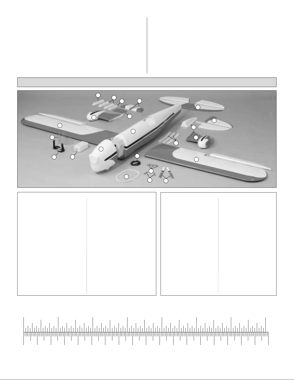
Parts List
1 Wing and Ailerons
2 Fuselage
3 Stab and Elevators
4 Fin and Rudder
5 Cowl
6 Cowl Ring
7 Wheel Pants
8 Rudder Fairing
9 Turtledeck
10 Fin Fairing
11 Stab Fairings
12 Wing Bolt Plate
13 Forward Wing Joiner
14 Wing Struts
15 Dorsal Fin
16 Engine Mount
17 Fuel Tank
18 Windscreen
19 Cockpit Coaming
20 Wing Dowels
21 Cowl Mount Blocks
Not Pictured:
Main Landing Gear
Tail Gear with Tailwheel
Aft Wing Joiner
Forward Servo Tray
Aft Servo Tray
Instrument Panel Decal
Hardware Bag
Replacement Parts:
GPMA2200 Wing Set
GPMA2201 Fuse Set
GPMA2202 Tail Set
GPMA2203 Cowl Set
GPMA2204 Windscreen
GPMA2205 Landing Gear Set
GPMA2206 Wheel Pants
GPMA2207 Wing Struts
GPMA2208 Rudder Fairing
• Whenever the term glue is written you should rely upon
your experience to decide what type of glue to use. When a
specific type of adhesive works best for that step the
instructions will make a recommendation.
• Whenever epoxy is specified you may use either 30minute epoxy or 6-minute epoxy. When 30-minute epoxy is
specified it is highly recommended that you use only 30minute (or 45-minute) epoxy because you will need the
working time and/or the additional strength.
• When you get to each step, read that step completely
through to the end before you begin. Frequently there is
important information or a note at the end of the step that
you need to know before you start.
• Photos and sketches are placed before the step they
refer to. Frequently you can study photos in following steps
to get another view of the same parts.
To convert inches to millimeters, multiply inches by 25.4
(1) 60-120 Engine mount
(2) Metal solder-on clevis
(2) Brass body for screw-lock
pushrod connector
(4) Large nylon control horns
(2) 1/4-20 x 2" nylon wing bolts
(3) Nylon clevis
(2) Hump strap for 1/8" wire
(2) Trees of 4 flat nylon LG straps
(1) Ball link
(2) Nylon retainers for screw-lock
(1) CA hinge strip
(2) Nylon faslinks
(2) 6-32 torque rod horn
(2) 4-40 hex nuts
(4) 8-32 blind nuts
(1) 0-80 hex nut
(1) 3/16" x 36" guide tube
(7) Silicone retainers
(2) 6-32 set screws
(2) 6-32 x 1/4" cap screws
(7) #4 x 5/8" screws
(1) 0-80 threaded ball
(4) 2-56 x 3/4" cap screws
(4) 8-32 x 1-1/4" cap screws
(4) 8-32 x 1" cap screws
(2) 4-40 x 1/8" cap screws
(36)
#2 x 1/2" screws
(4) 3/16" wheel collars
(1) 2-56 x 12" threaded pushrod
(1) 2-56 x 36" threaded pushrod
(2) 2-56 x 6" threaded pushrods
(2) 4-40 x 36" threaded pushrods
(1) 6-32 x 1-1/2" threaded rod
(3) #4 flat washer
(8) #8 lock washer
(4) #8 flat washer
(2) Axles
Parts List
Hardware
10
7
1
18
16
17
11
15
5
8
12
2
19
6
3
4
9
7
13
1
21
20
14
Inch Scale
0" 1" 2" 3" 4" 5" 6" 7"
0 10 20 30 40 50 60 70 80 90 100 110 120 130 140 150 160 170 180
Metric Scale
Page 6
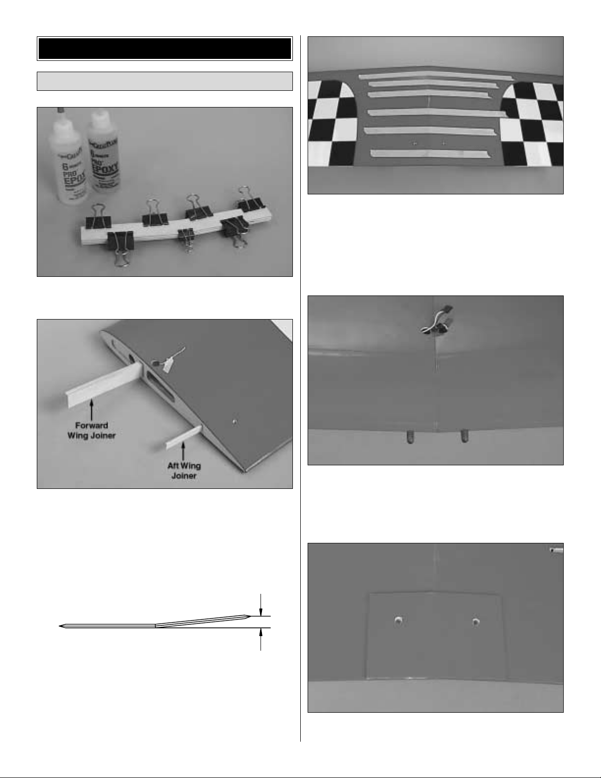
❏ 1. Use epoxy to glue the three plywood forward wing
joiners together. Wipe away excess epoxy before it hardens.
Refer to this photo for the following two steps.
❏ 2. Cut the covering from the pre-drilled holes in both wing
halves for the servo cords, the wing dowels and the wing
bolts. Route the end of the string through the servo wire hole
in the top of both wing halves and tape the end of the string
to the top of the wing.
❏ 3. Test join the wing halves using the forward wing joiner
you glued together in the first step and an additional plywood
aft wing joiner that fits in the slot near the trailing edge.
Make adjustments where necessary for a good fit. There
should be no gap between the wing halves. When one wing
half is lying flat on the workbench the tip of the other half
should be approximately 6-5/8" from the workbench.
❏ 4. Separate the wings and remove the joiners. Thoroughly
coat all mating surfaces, including the inside of the wings
where the joiners fit, with 30-minute epoxy , then glue the wings
together. Use masking tape to tightly hold them together until
the epoxy has hardened. Excess epoxy that gets on the
covering can be easily removed before it hardens with a tissue
dampened with denatured alcohol or other suitable solvent.
❏ 5. Round one end of both hardwood wing dowels. Use
epoxy to glue the dowels into the wing with the rounded
ends forward. Be certain approximately 1/2" of the dowels
protrudes from the wing. While you've got some epoxy
mixed up, lightly coat the dowels to fuelproof them.
❏ 6. Use a sharp, new #11 blade to trim the covering from
the bottom of the wing for the 1/8" plywood wing bolt plate.
6-5/8"
Join the Wing Halves
BUILD THE WING
6
Page 7
Use care to cut just through the covering, while not cutting
into the wood. Glue the wing bolt plate into position. Af ter the
glue hardens, use the holes in the top of the wing as a guide
to drill 17/64" (or 1/4") holes through the wing bolt plate.
Do the right aileron first.
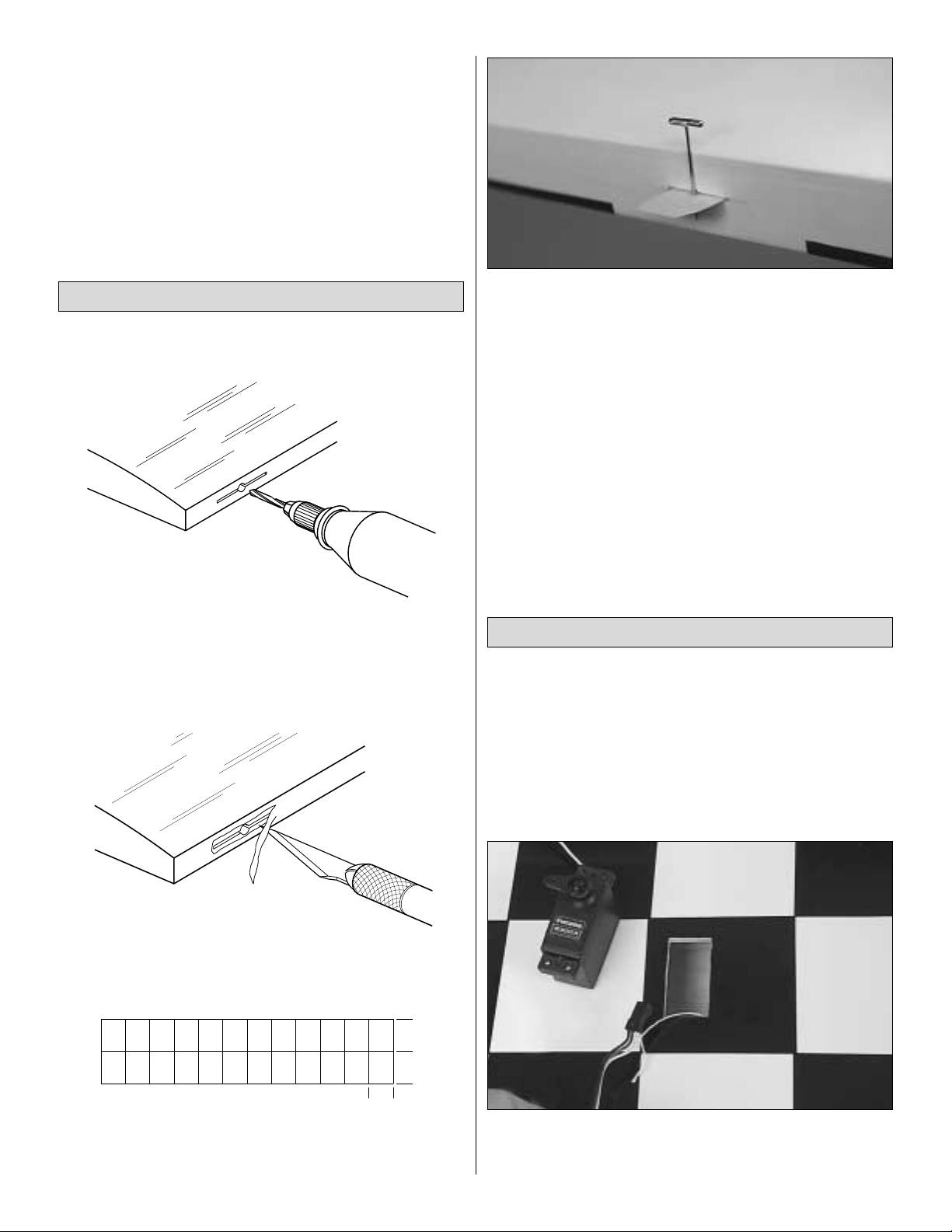
❏ ❏ 1. Drill a 3/32" hole 1/2" deep in the center of the
hinge slots in the right wing panel and right aileron. A drill
does the job okay , but a high-speed tool like a Dremel works
better. Insert a #11 knife blade into the slots, working it back
and forth a few times to clean them out.
❏ ❏ 2. Cut the covering from the hinge slots.
❏ ❏ 3. Cut four 3/4" x 1" hinges as shown in the sketch
from the supplied CA hinge strip.
❏ ❏ 4. Test fit the aileron to the wing with the hinges. If the
hinge slots are too tight, remove the hinges and use a #11
blade to slightly open the slots. If necessary, insert a small
pin through the center of the hinges so they remain centered
when joining the aileron to the wing.
❏ ❏ 5. With the aileron joined to the wing, remove any pins
used to center the hinges. Be certain there is a small gap
between the leading edge of the ailerons and the wing—just
enough to slip a piece of paper through or to see light through.
❏ ❏ 6. Apply six drops of thin CA to both sides of all the
hinges. Allow a few seconds between drops to allow the
hinge slots to fully absorb the CA.
❏ 7. Join the left aileron to the wing the same way.
Do the right aileron first.
❏ 1. Cut the covering from the right aileron hatch in the
bottom of the wing.
❏ 2. Connect a servo extension cord to your aileron servo
wire. Secure the connection with vinyl tape, heat shrink
tubing, or special clips intended for that purpose.
❏ 3. Tie the end of the string that is taped inside the wing
to the end of the servo wire. Pull the wire through the ribs
and out of the hole in the middle of the wing.
Hook Up the Ailerons
1"
1"
3/4"
AWAY FROM THE SLOT
CUT THE COVERING
DRILL A 3/32" HOLE
1/2" DEEP, IN CENTER
OF HINGE SLOT
Hinge the Ailerons
7
Page 8
Refer to this photo for the following two steps.
❏ 4. Drill 1/16" holes in the wing for mounting the aileron
servo. Add a few drops of thin CA to the holes and allow to
harden, then mount the servo to the wing. Note that, for the
right aileron servo shown in the photo, the servo arm points
towards the middle of the wing and the output shaft on the
servo is toward the trailing edge of the wing. When
instructed to mount the left aileron servo, it should “mirror”
the right servo with the servo arm pointing toward the middle
of the wing and the output shaft toward the trailing edge.
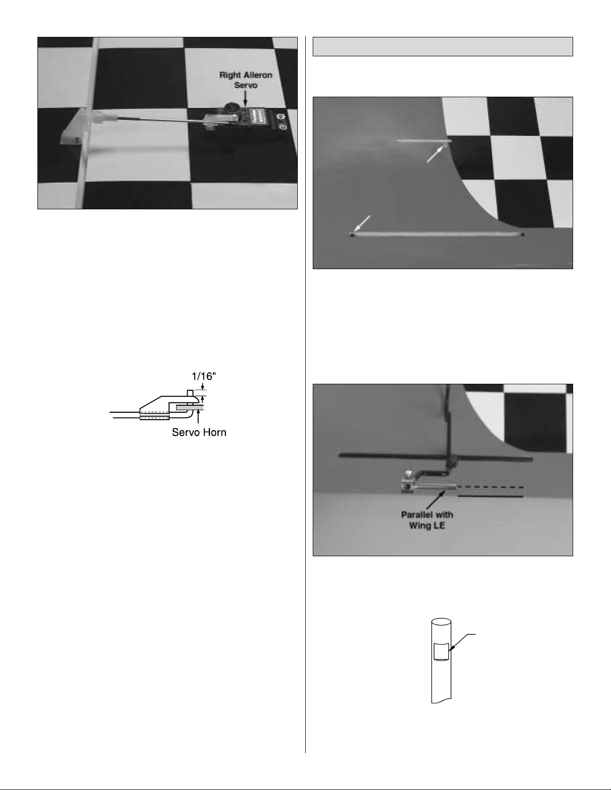
❏ 5. Make the aileron pushrod as shown in the photo using
a 2-56 x 6" threaded one-end pushrod, a nylon clevis, a
large nylon control horn, two #2 x 1/2" screws, a nylon
Faslink and a silicone retainer. After drilling 1/16" holes in
the aileron for the #2 x 1/2" screws, harden the holes by
adding a few drops of thin CA and allowing it to harden
before mounting the control horn. After you make the “L”
bend in the pushrod wire for the nylon Faslink, trim the end
of the wire so that approximately 1/16" protrudes from the
Faslink as shown in the sketch. If necessary, enlarge the
holes in the servo arm with a #48 (or 5/64") drill.
❏ 6. Mount the left aileron servo and connect it to the left
aileron the same way . Be cert ain you've inst alled the screws
that hold the servo arms to the servos when you're done
hooking up the ailerons!
Do the right one first so yours looks like the photos.
❏ ❏ 1. Cut the covering from the grooves in the landing
gear rails in the bottom of the right wing panel. Trim the aft
rail (as indicated by the arrow in the photo) to accommodate
the aft strut where it “angles up” toward the main strut. Trim
the edge of the hole in the forward rail (as indicated by the
arrow in the photo) to accommodate the bend in the main
strut. Test fit the right landing gear into the wing.
❏ ❏ 2. Place an axle on the landing gear so it is parallel
with the leading edge of the wing. Temporarily tighten a
6-32 x 1/4" cap screw that holds the axle on.
❏ ❏ 3. Loosen the screw and remove the axle from the
landing gear. Remove the landing gear from the wing. File a
flat spot on the landing gear where the screw made its mark.
Flat Spot
Mount the Landing Gear
8
Page 9
❏ ❏ 4. Reposition the axle onto the gear and tighten the
screw. Be certain that the screw has “landed” on the flat spot
and that the axle has remained parallel with the leading edge
of the wing. If not, remove the axle and adjust the flat spot as
necessary . Securely mount the axle to the landing gear with the
6-32 x 1/4" cap screw and a drop of threadlocker on the screw.
❏ ❏ 5. Fit of the right wheel pant over the gear. (The right
wheel pant is the one that fits the right wing best when fit over
the landing gear.) Slip a wheel collar followed by a 4" wheel
and another wheel collar onto the axle. Adjust the position of
the wheel collars until the wheel is centered in the opening in
the wheel pant. Temporarily tighten the outer wheel collar to
the axle with a 6-32 set screw.
Refer to this sketch for the following two steps.
❏ ❏ 6. With the wheel pant positioned on the wing so the
wheel is centered in the opening, drill 1/16" holes through
the wheel pant into the landing gear blocks where indicated
by the arrows in the sketch. Enlarge the holes in the wheel
pants only with a 3/32" drill, then mount the pants to the
wing with four #2 x 1/2" screws.
❏ ❏ 7. Drill 1/16" holes into the wing over the landing gear
rails for the landing gear straps. Secure the landing gear
to the wing with four nylon landing gear straps and eight
#2 x 1/2" screws.
❏ ❏ 8. Now that the final position of the wheel pant, wheel
and wheel collars has been determined, remove the wheel
pant and the wheel from the landing gear. File a flat spot on
the axle for the set screw in the wheel collar that holds on
the wheel. Reassemble all the parts using a drop of
threadlocker on the set screw in the wheel collar.
❏ 8. Return to step 1 and mount the left landing gear and
wheel pant to the wing the same way.
While working on the fuse, it helps to have a stand or a
cradle. We use a Robart Super Stand II (ROBP1402).
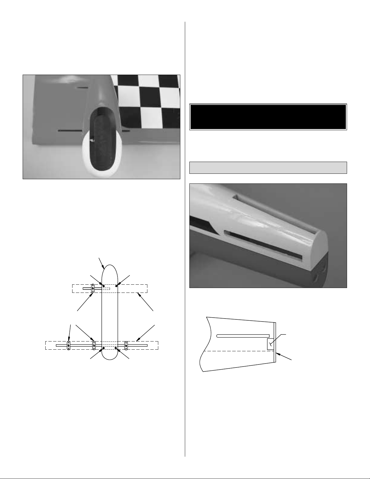
❏ 1. Trim the covering from the fuse over the slots for the
stab and fin and over the holes for the rudder control cables.
❏ 2. View the aft former through the slot for the rudder.
Check to see if there is a balsa hinge block glued to the
former for the bottom rudder hinge. If there isn't one, make
a 1/4" x 1/4" x 1-1/2" (or a similar size) hinge block from a
balsa stick and glue it into position as shown in the sketch.
❏ 3. Temporarily install the stab in the fuse. At the trailing
edge, measure the distance between the tips and the fuse.
Position the stab until both measurements are equal and the
trailing edge of the stab is centered.
1/4" x 1/4" x 1-1/2"
Balsa Hinge Block
Aft Former
Install the Stab
JOIN THE TAIL SURFACES
TO THE FUSE
Top of Wheel Pant Where
It Contacts the Wing
Landing Gear
Straps
Landing Gear
Blocks
9
Page 10

❏ 4. Turn the fuse upside-down. Stick a T-pin through the
bottom of the fuse centered over the middle stringer. Tie a
small loop in one end of a 50" piece of non-elastic string
such as monofilament or Kevlar fishing line. Slip the loop in
the string over the T-pin.
❏ 5. Fold a piece of masking tape over the string near the
other end and draw an arrow on it. Slide the tape along the
string and align the arrow with one end of the stab as shown
in the photo. Swing the string over to the same position on
the other end of the stab. While keeping the stab centered,
adjust the stab and slide the tape along the string until the
arrow aligns with both sides of the stab. Be certain the stab
remains centered, side-to-side, during this process.
❏ 6. Use a fine-point felt-tip pen such as a Top Flite
®
Panel
Line Pen (TOPQ2510) to mark the outline of the fuse onto
the top and bottom of the stab.
❏ 7. Remove the stab. Use a sharp, new #11 blade to trim
the covering from the stab along the lines you marked. The
same as when you cut the covering from the wing, use care
to cut just through the covering, thereby not cutting into the
wood. Important: Cutting into the balsa will weaken the stab
which could cause it to break during flight. Using a sharp
blade reduces the pressure required to cut the covering,
thereby reducing the chance of cutting into the balsa.
❏ 8. Peel the covering from the stab. Remove any ink with
a piece of a tissue dampened with denatured alcohol.
❏ 9. Thoroughly coat all joining areas of the stab and fuse with
30-minute epoxy. Reinsert the stab into the fuse. Wipe away
excess epoxy using tissue dampened with denatured alcohol.
Center the stab the same way you did before (measuring the
distance from side to side and using the pin-and-string). Do not
disturb the fuse until the epoxy has fully hardened.
❏ 1. Test fit the fin into the fuse. Be certain the trailing edge
is even with the aft end of the fuse. If the fin cannot be
positioned far enough aft to achieve this, trim the bottom of
the trailing edge of the fin.
❏ 2. The same as you did the stab, draw a line around the
fin where it meets the fuse. Remove the fin and carefully cut,
then remove the covering.
❏ 3. Use 30-minute epoxy to glue the fin to the fuse. Before
the epoxy hardens, use a Hobbico®Builder's Triangle
(HCAR0480) to check if the fin is perpendicular to the stab.
If necessary , use masking tape to pull the tip of the fin to one
side or the other until it is “square.”
❏ 4. The same as you did when hinging the ailerons, drill a
3/32" hole, 1/2" deep in the center of the hinge slots in the stab,
fin, elevators and rudder. Cut the covering from the hinge slot s,
then cut nine hinges from the remainder of the CA hinge strip.
Install the Fin
10
Page 11

❏ 5. There should be four hinge slots for the rudder—three
in the fin and one in the fuse. If there isn't one in the fuse,
cut a hinge slot about 1/2" from the bottom. Cut a
corresponding hinge slot in the rudder.
❏ 6. Use coarse sandpaper to roughen the joining edges of
both halves of the molded plastic rudder fairing. Use small
clamps to hold the fairing together , then drip a small amount
of thin CA along the seams on the inside. Allow to harden.
❏ 7. Test fit the rudder fairing to the rudder. If necessary,
trim the rudder to accommodate the fairing so it will go on all
the way.
❏ 8. Test fit the rudder and fairing to the fin with the hinges.
Cut a slot in the front of the fairing to accommodate the
bottom rudder hinge.
Now that we've fit the rudder fairing, let's set it aside and
hook up the rudder. The rudder fairing will be permanently
mounted after the controls are hooked up.
❏ 9. Cut the covering from the hole in both sides of the
rudder. Thread the 6-32 x 1-1/2" threaded rod into the
rudder until it is centered. Thread a 6-32 nylon torque rod
connector onto both ends of the rod until the top of the
connectors are even with the ends of the rod. Once again
temporarily fit the rudder to the fin. If the connectors do not
align with the holes in the back of the fuse, enlarge the holes
as necessary.
Before the forward and aft servo trays can be mounted, first
the fuel tank has to be installed. But before that can be
done, the blind nuts for the engine mount should be installed
in the back of the firewall.
❏ 1. Cut out the engine mount bolt pattern template
provided on page 27. Align the lines on the template with the
lines scribed into the firewall. Drill 7/32" holes through the
firewall for the 8-32 blind nuts.
❏ 2. Install the 8-32 blind nuts in the back of the firewall
using an 8-32 x 1-1/4" socket head cap screw (SHCS) and
#8 washers to pull the blind nuts all the way in.
Connect the Pushrods
HOOK UP THE CONTROLS
11
Page 12

❏ 3. Assemble the fuel t ank. Arrange the stopper and tubes
as shown in the photo, then fit them into in the tank. Tighten
the screw to expand the stopper, thus sealing the tank. Be
certain the fuel line weight (clunk) at the end of the fuel line
inside the tank does not contact the rear of the tank.
Otherwise, the line may become stuck during flight and
discontinue fuel flow. Remember (or use a felt-tip pen to
mark) which tube is the fuel pick-up tube and which tube is
the vent (that will be connected to the pressure fitting on the
engine muffler).
❏ 4. Install the fuel tank so the neck fits through the hole in
the firewall. Be certain that you have installed the tank so
the vent tube inside the tank is pointing upward. Use #64
rubber bands (not included) to hold the tank to the tank floor .
❏ 5. Test fit the rudder servo and both elevator servos in
the 1/8" plywood aft servo tray. Make adjustments if
necessary to the tray to accommodate your servos. Drill
1/16" holes in the tray for mounting the servos, then add a
few drops of thin CAto the holes and allow to harden. Mount
your servos.
❏ 6. Before installing the 1/8" plywood forward servo tray,
use a pin to poke a hole through the fuselage sheeting at the
middle of the bottom edge of the hardwood wing strut
mounting blocks on both sides of the fuse. The hole will be
a future reference for mounting the wing struts later on.
Refer to this photo for the following two steps.
❏ 7. Securely glue the aft servo tray to the crutches using
epoxy (it may be easier to do this without the servos in the
tray). For additional strength, mix Great Planes Pro Milled
Fiberglass (GPMR6165) into the epoxy. Use clamps to hold
the aft servo tray in position until the epoxy hardens.
❏ 8. Removal of the fuel tank will not be possible after the
forward servo tray is glued into position. If you would like to
be able to remove the fuel tank after the forward servo tray
is installed (for future maintenance to the tank), make the
forward servo tray removable. This can be done by using
epoxy to glue 3/16" x 3/8" x 6-3/8" (or a similar size)
basswood rails (not supplied) to the fuse crutches. Drill
three 3/32" holes through both rails before gluing them into
position. Use #2 x 1/2" screws (not supplied) to secure the
tray to the rails. If you prefer not to make the forward servo
tray removable, use epoxy to glue it into position the same
way you did the aft servo tray.
❏ 9. Connect the rudder servo to the rudder using the pull-
pull cable system.
❏ 10. Cut the covering from the elevator guide tube exits in
both sides of the fuse. Make two elevator pushrods by
threading a 4-40 nut and a 4-40 clevis onto two 4-40 x 36"
threaded one-end pushrods. Insert the pushrods into the
guide tubes with the clevises on the aft end.
12
Page 13

❏ 11. Connect the clevis on the end of both pushrods to the
outer hole of a large control horn. Bend the pushrods as
necessary—but as little as possible—to position the control
horns on the elevator as shown in the sketch. Drill 3/32" holes
through the elevators, then mount the horns with 2-56 x 3/4"
SHCS and the nylon plate that came with the control horn.
❏ 12. Cut the front end of the pushrods to the correct
length, then read the following Expert Tip and solder a clevis
to the end of both pushrods. Connect the pushrods to the
elevator servos. If you prefer to solder the clevises to the
pushrods out of the model, you will have to slightly
straighten the bends you made before reinserting the
pushrods through the guide tubes.
How to solder.
A. Use denatured alcohol or other solvent to remove
residual oil from the pushrod.
B. Use coarse sandpaper to thoroughly roughen the end
of the pushrod where it is to be soldered.
C. Apply a few drops of soldering flux to the end of the
pushrod, then use a soldering iron or a torch to heat the end
of the pushrod. Coat the end of the pushrod with silver solder
(GPMR8070) by touching the solder to the pushrod. The
heat of the pushrod should melt the solder—not the flame of
the torch or soldering iron—thus allowing the solder to flow.
Note: Do not use silver solder for electrical soldering.
D. Join the clevis to the pushrod. Add another drop of flux,
then heat and add solder. The same as before, the heat of
the parts being soldered should melt the solder thus
allowing it to flow. Allow the joint to cool without disturbing.
Avoid excess blobs, but make certain the joint is thoroughly
soldered. The solder should be shiny, not rough. If
necessary, heat the joint again and allow to cool slowly
without disturbing.
E.After the joint has solidified but while it is still hot, carefully
use a cloth to wipe away soldering flux. Important:After the
joint cools, coat with oil to protect it from rusting.
Refer to this photo while mounting the tail gear.
❏ 1. Drill a 1/8" hole through the center of the bottom of the
fuse for the tail gear wire 5-7/8" from the aft end. Optional:
Use a 5/32" brass tube sharpened at one end to drill the
hole. Cut 1" from the end of the brass tube and glue it into
the hole. This will provide a bearing for the tail gear wire.
❏ 2. Insert the tail gear wire into the hole (or brass tube).
Keeping the tail gear wire centered, place two nylon humpstraps on the wire where shown in the photo. Drill 1/16"
holes for the screws that will hold the straps into position.
Add a few drops of thin CAto the holes and allow to harden.
Mount the straps to the fuse with four #2 x 1/2" screws.
❏ 3. Drill a 3/16" hole (or use a 3/16" brass tube sharpened
at the end) through the bottom of the fuse in alignment with
the arm on the right side of the tail gear. Roughen one end
of the 3/16" x 36" pushrod guide tube. Guide the tube
through the fuse, so the roughened end is in the hole you
cut. Glue the tube into position. Trim the end of the tube so
it is even with the bottom of the fuse.
❏ 4. Cut the front of the guide tube about 1-1/2" short of the
rudder servo arm. Save the piece you just cut off for the
throttle. Make the tail gear pushrod from the 2-56 x 36"
Mount the Tailgear
Correct Incorrect
13
Page 14

wire by bending the threaded end to join the steering arm on
the right side of the tail gear . Connect the pushrod to the tail
gear with a nylon ball link, a 0-80 threaded ball and a 0-80
nut and a small drop of threadlocker.
❏ 5. Cut the other end of the wire to the correct length and
connect it to the rudder servo arm as shown in the sketch
with a brass Quick Connector body, a nylon retainer and a
4-40 x 1/8" screw.
❏ 6. Make a balsa or plywood brace for the front end of the
tail gear guide tube. Temporarily disconnect the pushrod
from the servo and slide the brace over the guide tube.
Connect the pushrod, then glue the brace into position as
shown in the photo.
❏ 1. Disconnect the clevises from the rudder and remove
the rudder from the fin. Measure the distance from the
bottom of the third hinge slot to the threaded rod that goes
through the rudder. As you can see in the rudder in the
photo, the distance is about 4-1/4".
❏ 2. Remove a torque rod horn and the threaded rod from
the rudder. Temporarily fit the rudder fairing over the rudder.
Using the measurement taken in the previous step, trim the
rudder fairing as necessary to accommodate the threaded
rod, torque rod horns and the clevises.
❏ 3. Making certain the leading edge of the rudder fairing
is parallel with the leading edge of the rudder, glue the
rudder fairing into position. Install the threaded rod. Add a
few drops of thin CA and allow to harden. Thread on the
torque rod horns.
Join the Tail Fairings
RETAINER
14
Page 15

❏ 4. Use curved-tip scissors or a hobby knife to carefully
trim the molded fin and stab fairings. Note that the longer
fairing is the one for the fin. Trim the fairings as necessary
for a good fit, then carefully glue them to the fuse using thin
CA sparingly.
❏ 5. Join the rudder to the fin and the elevators to the stab
with the hinges. The same way you did the ailerons, use thin
CA to glue in the hinges. Connect the rudder cables to the
rudder and connect the elevator pushrods to the elevators.
❏ 1. Use four 8-32 x 1-1/4" SHCS, #8 lock washers and #8
flat washers to mount the Great Planes 60-120 Adjustable
Engine Mount to the firewall, simultaneously adjusting the
mount to fit your engine. Be certain the mount is centered on
the vertical line on the firewall. Tighten the screws and make
certain they do not contact the fuel tank. If they do, move the
tank slightly aft, or add additional washers to the screws.
❏ 2. Mount the back plate of the spinner to the engine.
Position the engine on the mount, so the back plate will be
5-7/8" from the firewall. This will provide the correct
clearance between the spinner and the cowl. Temporarily
hold the engine to the mount with clamps. Use a Great
Planes Dead Center™Hole Locator (GPMR8130—shown in
the photo) or another suitable method to mark the locations
of the holes for mounting the engine to the engine mount.
❏ 3. Drill #29 (or 9/64") holes through the engine mount at
the marks you made, then tap 8-32 threads into the holes.
Mount the engine to the mount with four 8-32 x 1" SHCS
screws and #8 lock washers.
Refer to this photo while hooking up the throttle.
❏ 4. Mount the throttle servo in the servo tray the same way
you mounted the rudder and elevator servos (drill 1/16"
holes, harden the holes with thin CA).
❏ 5. Place a brass Quick Connector body on the carb arm
of your engine and secure it with a nylon retainer. Drill a
3/16" hole through the firewall in alignment with the Quick
Connector. Cut the remainder of the tail wheel guide tube
you saved to the correct length for the throttle pushrod guide
tube. Use coarse sandpaper to roughen the tube so glue will
adhere. Guide the tube through the hole you drilled in the
firewall for the throttle and glue it to the firewall.
Mount the Engine
15
Page 16

❏ 6. Make the throttle pushrod from a 2-56 x 12" threaded
one-end pushrod and connect it to the throttle servo with a
nylon clevis. Cut the other end to the correct length and fasten
it to the Quick Connector body with a 4-40 x 1/8" SHCS.
❏ 1. Cut the holes in the front of the cowl for the engine crank
shaft and for the main air inlet. ADremel with a carbide cutter,
followed by a drum sander, works the best. Use protective
goggles and a particle mask when cutting fiberglass. Followup by sanding the openings to remove sharp edges.
❏ 2. Use 30-minute epoxy mixed with lightweight Top Flite
Microballoons Filler (optional, TOPR1090) to glue the 1/8"
plywood cowl ring inside the cowl 1" from the aft edge.
❏ 3. Refer to the following photo, then use 30-minute epoxy
to glue the three 9/16" x 9/16" x 1" cowl mount blocks to
the fuselage as shown. Note: The end-grain of the wood
blocks readily absorbs epoxy, so first coat one end of each
block with epoxy and let them sit for a few minutes. Apply a
second, then a third coat of epoxy before positioning the
blocks on the fuse and clamping them into position.
❏ 4. Position the cowl over the cowl mount blocks on the
fuse. If necessary, trim the blocks to accurately fit the cowl.
As you can see in the photo, 1/8" leftover plywood glued to
the ends of the two side cowl mount blocks was required.
Refer to the following photos while mounting the cowl.
❏ 5. Position the cowl on the fuse and mount the spinner.
Align the front of the cowl with the spinner and the back of the
cowl with the fuse. With the cowl in alignment, drill 3/32" holes
through the cowl into the cowl mount blocks. Remove the
cowl and enlarge the holes in the cowl only with a 1/8" drill.
❏ 6. Screw a #4 x 5/8" screw into each cowl mount block,
then remove. Add a few drops of thin CA to the holes and
allow to harden. Test fit the cowl to the fuse with three #4 x
5/8" screws and #4 washers.
❏ 7. Fashion a mount for a fuel filler valve, should you
decide to use one, from 1/8" plywood (not included). As
shown in the photo, we used a Great Planes Easy-Fueler
™
for glow fuel (not included with this kit, GPMQ4160). We
also used a Model Products #021 Remote Single Lock
remote glow plug adapter (MODP1221). Note that the filler
valve is positioned behind the ply cowl ring and the front of
the fuse to allow easy installation of the cowl.
❏ 8. Cut holes in the cowl where necessary for the engine
exhaust/muffler, needle valve, glow plug igniter (or remote
glow plug hook up) and fuel filler.
❏ 9. Use epoxy or fuelproof paint to coat bare wood such
as the cowl ring, the cowl mounting blocks and the mount for
the fuel filler valve.
Mount the Cowl
16
Page 17

❏ 10. Consider the amount of air entering and exiting the
cowl for engine cooling. If you feel it necessary, cut
additional holes in the cowl for cooling. Our prototype, with
the O.S.®MAX .91 FS, required no additional holes in the
cowl for cooling, but other engines may have different
requirements. Cowled-in engines should operate at slightly
rich needle valve settings to be certain there is an adequate
fuel/oil supply which aids in engine cooling and reliability.
❏ 1. Connect the servos, aileron extension cord and on/off
switch to the receiver. Wrap the receiver and battery pack in
at least 1/4" of R/C foam rubber and securely mount them in
the fuse using Velcro
®
Hook & Loop straps (GPMQ4480),
rubber bands or another suitable, yet secure method. Simply
stuffing them into place with additional foam is not sufficient.
As you can see in the photos, we removed the forward servo
tray and used #64 rubber bands strapped to hardwood sticks
to hold the battery pack and receiver. The battery pack was
mounted to the top of the tray, so it would not interfere with
the throttle servo. Note: With the battery pack and receiver
mounted where shown, our prototype Ryan with an O.S.
MAX .91 FS balanced within the recommended C.G. range
shown on page 20 without additional ballast. If, upon
checking the C.G., you find that the model is nose-heavy or
tail-heavy, you could relocate the battery pack to minimize or
eliminate any additional ballast required.
❏ 2. Mount the on/off switch and an external charge jack,
should you decide to use one, on the side of the fuselage
opposite the engine exhaust. As shown in the photo we use
a Great Planes Switch & Charge Jack Mounting Set
(GPMM1000). The external charge jack allows us to monitor
the voltage of the receiver battery pack before each flight
without removing the wing.
❏ 3. Make certain all the servo arms are secured to the
servos with the screws that came with them and that all the
clevises have retainers on them.
❏ 4. Extend the receiver antenna and guide it out of the
fuselage and connect it to the fin. Be certain there is a strain
relief on the antenna to keep stress off the solder joint inside
the receiver. On our prototype we drilled a 1/8" hole through
Finish Radio Installation
17
Page 18

the top stringer aft of the cockpit and routed the antenna
through a piece of tubing exiting the fuse. The other end of
the antenna was connected to a hook made from a cut-off
servo arm connected to a small rubber band and a T-pin
inserted into the leading edge of the fin.
Refer to this photo while mounting the wing struts.
❏ 1. Bolt the wing to the fuselage with the 1/4" x 2" nylon
wing bolts. Bevel both ends of one of the balsa wing struts
to match the left side of the fuse and the wing. Note that the
top of the strut should be positioned so that when a hole is
drilled through it and the fuse, the hole will go through the
strut block inside (remember you made a small hole through
the fuse with a pin indicating the location of the block).
❏ 2. Hold the strut in position, then drill 3/32" holes through
both ends of the strut into the mounting blocks in the wing
and the fuse. The holes should be perpendicular to the top of
the strut. Enlarge the holes in the strut only with a 1/8" drill.
❏ 3. Add a few drops of thin CAto both ends of the strut to
harden the holes and to fuelproof the exposed balsa. Mount
the strut to the fuse and wing with two #4 x 5/8" screws.
❏ 4. Mount the other strut to the right side of the fuse the
same way. Mark the struts as right and left in an
inconspicuous location, so you will know how to put them
back on when you get to the flying field.
❏ 1. Use black, fuelproof paint to coat the inside of the
cockpit. After the paint dries, place the instrument panel
sticker on the instrument panel.
❏ 2. Have a helper hold the clear plastic windscreen in
position on the fuse. Use a fine-point felt-tip marker to draw a
line on the fuse around the front edge of the windscreen. Use
a hobby knife with a new #1 1 blade to cut through the covering
along the line you marked. If you wish to make a flat black antiglare panel (as shown in the photo), remove the portion of
covering behind the line you cut. Use the piece of covering as
a template to cut another piece of covering from flat black
MonoKote®film (or use fine sandpaper to scuff a piece of
regular black MonoKote film). Iron the “anti-glare” panel you
cut from the black MonoKote film into position, leaving a 1/16"
gap of exposed balsa between the black and the white. If you
are not going to make a black anti-glare panel, simply cut the
covering 1/16" in front of the line you already cut. Remove the
1/16" strip of covering from the fuse, thereby leaving a 1/16"
strip of exposed balsa that the windscreen can be glued to.
Refer to this photo while you are finishing the cockpit.
❏ 3. Use a #11 blade to split the rubber tubing used for the
cockpit coaming. Fit the coaming around the cockpit with
the ends joining at the rear but don't glue it into position. It
isn't necessary for the ends of the coaming to meet up,
because it will be trimmed to accommodate the turtledeck.
Finish the Cockpit
Drill Holes
Perpendicular
90˚
90˚
Mount the Wing Struts
FINAL SCALE DETAILS
18
Page 19

❏ 4. Trim the molded plastic turtledeck to fit the fuse, then
temporarily fit it into position. Trim the cockpit coaming to
accommodate the turtledeck. If you plan to route the
receiver antenna through the top of the fuse, cut a hole in
the turtledeck to pass the antenna. Glue the turtledeck to the
fuse with thin CA.
❏ 5. If you prefer, you can glue the coaming to the fuse with
thin CA, but the coaming stays put by itself, so it isn't really
necessary to glue it.
❏ 6. Glue the windscreen to the fuse. If great care is used
and it is applied sparingly, thin CAcan be used for this. If too
much thin CAis used, fogging of the canopy and covering will
be the result. Another type of adhesive recommended is J &
Z Products Z R/C 56 canopy glue (JOZR5007), but it dries in
a few hours, so the canopy will have to be taped into position
while the glue is drying.
❏ 7. Apply Great Planes 1/4" white Kwik Stripe (GPMQ1610)
striping tape around the base of the windscreen where it meets
the fuse. For an added touch, apply 1/8" chrome striping tape
(GPMQ10884) around the aft edge of the windscreen.
❏ 8. Assemble, paint, then glue a pilot in the cockpit. We
used a Williams Bros. #62500 1/4-scale Standard pilot
(WBRQ2625) with 1/4" balsa sticks glued between the base
of the pilot and the cockpit floor to raise him 1/4".
❏ 9. Cut out the molded dorsal fin, then glue it into position
with thin CA as shown in the photo.
❏ 1. Turn on the transmitter and receiver and center the
trims. If necessary, remove the servo arms from the servos
and reposition them so they are centered.
❏ 2. If necessary, adjust the clevises on the pushrods so
the control surfaces are centered.
❏ 3. Make certain that the control surfaces and the
carburetor respond in the correct direction as shown in the
diagram above. If any of the controls respond in the
opposite direction, change their direction by using the servo
reversing feature in your transmitter. Note: Due to the fact
that the elevator pushrods are connected to opposite sides
of the elevator servos, the servos must be mixed
electronically (not with a “Y” connector).
Use a Great Planes AccuThrow™(or a ruler) to accurately
measure and set the control throw of each control surface
as indicated in the chart that follows. If your radio does not
have dual rates, we recommend setting the throws at the
low rate setting.
NOTE: Throws are measured at the widest part of the
elevators, rudder and ailerons. You will probably not be able
to achieve the recommended rudder control throws
mechanically (by changing the mounting locations of the
cables on the servo arm and rudder). You will have to use
the ATV in your transmitter. In our transmitter, we found it
necessary to turn the rudder ATV down to about 70% to
arrive at the correct throw.
Set the Control Throws
CARBURETOR WIDE OPEN
RUDDER MOVES RIGHT
LEFT AILERON MOVES DOWN
RIGHT AILERON MOVES UP
ELEVATOR MOVES UP
4-CHANNEL
TRANSMITTER
(STANDARD MODE 2)
4-CHANNEL RADIO SETUP
TRANSMITTER
4-CHANNEL
TRANSMITTER
4-CHANNEL
TRANSMITTER
4-CHANNEL
Check the Control Directions
GET THE MODEL READY TO FLY
19
Page 20

NOTE: This section is VERYimportant and must NOT be
omitted! A model that is not properly balanced will be
unstable and possibly unflyable.
At this stage your model should be in ready-to-fly condition
with all of the systems in place including the engine, landing
gear, covering and paint and the radio system.
❏ 1. Accurately mark the C.G. on the top of the wing on
both sides of the fuselage. The C.G. is located 4-3/16"
[106mm] back from the leading edge of the wing. This is
where your model should balance for your first flights. Later ,
you may wish to experiment by shifting the C.G. up to 1/4"
[6.4mm] forward or back to change the flying characteristics.
Moving the C.G. forward may improve the smoothness and
arrow-like tracking, but it may then require more speed for
takeoff and make it more difficult to slow down for landing.
Moving the C.G. aft makes the model more agile with a
lighter and snappier feel. In any case, start at the location
we recommend and do not at any time balance your model
outside the recommended range.
❏ 2. With the wing attached to the fuselage, all parts of the
model installed (ready to fly) and an empty fuel tank, place
the model upside-down on a Great Planes CG Machine, or
lift it upside-down at the balance point you marked.
❏ 3. If the tail drops, the model is “tail heavy” and weight
must be added to the nose to balance. If the nose drops, the
model is “nose heavy” and weight must be added to the tail
to balance. Nose weight may be easily added by using a
“spinner weight” (GPMQ4645 for the 1 oz. weight, or
GPMQ4646 for the 2 oz. weight). If spinner weight is not
enough use Great Planes (GPMQ4485) “stick-on” lead. A
good place to add stick-on nose weight is to the firewall
(don't attach weight to the cowl—it is not intended to support
weight). Begin by placing incrementally increasing amounts
of weight on the bottom of the fuse over the firewall until the
model balances. Once you have determined the amount of
weight required, it can be permanently attached. If required,
tail weight may be added by cutting open the bottom of the
fuse and gluing it permanently inside.
Note: Do not rely upon the adhesive on the back of the lead
weight to permanently hold it in place. Over time, fuel and
exhaust residue may soften the adhesive and cause the
weight to fall off. Use #2 sheet metal screws, RTV silicone
or epoxy to permanently hold the weight in place.
❏ 4. IMPORTANT: If you found it necessary to add any
weight, recheck the C.G. after the weight has been installed.
❏ 1. With the wing level, have an assistant help you lift the
model by the engine propeller shaft and the bottom of the
fuse under the TE of the fin. Do this several times.
❏ 2. If one wing always drops when you lif t the model, it means
that side is heavy . Balance the airplane by adding weight to the
other wing tip. An airplane that has been laterally balanced
will track better in loops and other maneuvers.
Balance the Model Laterally
4-3/16" [106mm]
4-3/16" [106mm]
From LE
Balance the Model
We recommend the following control surface throws:
High Rate Low Rate
ELEVATOR: 1" [25mm] up 3/4" [19mm] up
1" [25mm] down 3/4" [19mm] down
RUDDER: 1-9/16" [40mm] right 1-3/8" [35mm] right
1-9/16" [40mm] left 1-3/8" [35mm] left
AILERONS: 3/4" [19mm] up 1/2" [13mm] up
3/4" [19mm] down 1/2" [13mm] down
IMPORTANT: The balance point and control surface
throws listed in this manual are the ones at which the Ryan
flies best. Set up your aircraft to those specifications. If,
after a few flights, you would like to adjust the throws or
C.G. to suit your tastes, that is fine. Too much control
surface throw can make your model difficult to control or
force it into a stall, so remember “more is not always better .”
20
Page 21

No matter if you fly at an AMAsanctioned R/C club site or if you
fly somewhere on your own, you should always have your
name, address, telephone number and AMA number on or
inside your model. It is required at all AMAR/C club flying sites
and AMAsanctioned flying events. Fill out the identification tag
on page 27 and place it on or inside your model.
Follow the battery charging procedures in your radio
instruction manual. You should always charge your transmitter
and receiver batteries the night before you go flying and at
other times as recommended by the radio manufacturer.
NOTE: Checking the condition of your receiver battery pack
is highly recommended. All battery packs, whether it's a
trusty pack you've just taken out of another model, or a new
battery pack you just purchased, should be cycled, noting
the discharge capacity. Oftentimes a weak battery pack can
be identified (and a valuable model saved!) by comparing its
actual capacity to its rated capacity. Refer to the instructions
and recommendations that come with your cycler. If you
don't own a battery cycler, perhaps you can have a friend
cycle your pack and note the capacity for you.
Carefully balance your propellers before you fly. An
unbalanced prop is the single most significant cause of
vibration that can damage your model. Not only will engine
mounting screws and bolts loosen, possibly with disastrous
effect, but vibration may also damage your radio receiver
and battery. Vibration can also cause your fuel to foam,
which will, in turn, cause your engine to run hot or quit.
We use a Top Flite Precision Magnetic Prop Balancer
™
(TOPQ5700) in the workshop and keep a Great Planes
Fingertip Prop Balancer (GPMQ5000) in our flight box.
Follow the engine manufacturer's instructions to breakin your engine. After you run the engine on your model,
inspect your model closely to make sure all screws remain
tight and your pushrods and connectors are secure.
Ground check the operational range of your radio before the
first flight of the day. With the transmitter antenna collapsed
and the receiver and transmitter on, you should be able to
walk at least 100 feet away from the model and still have
control. Have an assistant stand by your model and, while
you work the controls, tell you what the control surfaces are
doing. Repeat this test with the engine running at various
speeds with an assistant holding the model, using hand
signals to show you what is happening. If the control
surfaces do not respond correctly, do not fly! Find and
correct the problem first. Look for loose servo connections
or broken wires, corroded wires on old servo connectors,
poor solder joints in your battery pack or a defective cell, or
a damaged receiver crystal from a previous crash.
Keep all engine fuel in a safe place, away from high heat,
sparks or flames, as fuel is very flammable. Do not smoke
near the engine or fuel; and remember that engine exhaust
gives off a great deal of deadly carbon monoxide. Therefore
do not run the engine in a closed room or garage.
Get help from an experienced pilot when learning to
operate engines.
Use safety glasses when starting or running engines.
Do not run the engine in an area of loose gravel or sand; the
propeller may throw such material in your face or eyes.
Keep your face and body as well as all spectators away from the
plane of rotation of the propeller as you start and run the engine.
Keep these items away from the prop: loose clothing, shirt
sleeves, ties, scarfs, long hair or loose objects such as
pencils or screwdrivers that may fall out of shirt or jacket
pockets into the prop.
Use a “chicken stick” or electric starter to start the engine.
Do not use your fingers to flip the propeller. Make cert ain the
glow plug clip or connector is secure so that it will not pop
off or otherwise get into the running propeller.
Failure to follow these safety precautions may result
in severe injury to yourself and others.
ENGINE SAFETY PRECAUTIONS
Range Check
Ground Check
Balance Propellers
Charge the Batteries
Identify Your Model
PREFLIGHT
21
Page 22

Make all engine adjustments from behind the rotating propeller .
The engine gets hot! Do not touch it during or right after
operation. Make sure fuel lines are in good condition so fuel
will not leak onto a hot engine, causing a fire.
To stop a glow engine, cut off the fuel supply by closing off
the fuel line or following the engine manufacturer's
recommendations. Do not use hands, fingers or any other
body part to try to stop the engine. To stop a gasoline
powered engine, an on/off switch should be connected to
the engine coil. Do not throw anything into the propeller of a
running engine.
Read and abide by the following Academy of Model
Aeronautics Official Safety Code:
1. I will not fly my model aircraft in sanctioned events, air
shows, or model flying demonstrations until it has been
proven to be airworthy by having been previously
successfully flight tested.
2. I will not fly my model aircraft higher than approximately
400 feet within 3 miles of an airport without notifying the
airport operator. I will give right of way to and avoid flying in
the proximity of full scale aircraft. Where necessary an
observer shall be used to supervise flying to avoid having
models fly in the proximity of full scale aircraft.
3. Where established, I will abide by the safety rules for the
flying site I use and I will not willfully and deliberately fly my
models in a careless, reckless and/or dangerous manner.
7. I will not fly my model unless it is identified with my
name and address or AMAnumber, on or in the model.
9. I will not operate models with pyrotechnics (any device
that explodes, burns, or propels a projectile of any kind).
1. I will have completed a successful radio equipment
ground check before the first flight of a new or repaired model.
2. I will not fly my model aircraft in the presence of
spectators until I become a qualified flier , unless assisted by
an experienced helper.
3. I will perform my initial turn after takeoff away from the
pit or spectator areas and I will not thereafter fly over pit or
spectator areas, unless beyond my control.
4. I will operate my model using only radio control
frequencies currently allowed by the Federal
Communications Commission...
Since the Great Planes Ryan STA qualifies as a “giant
scale” model and is therefore eligible to fly in IMAA
events, we've printed excerpts from the IMAA Safety
Code which follows.
For the purpose of the following IMAASafety Code, the term
Giant Scale shall refer to radio controlled model aircraft,
either scale or non-scale, which have a wingspan of 80
inches or more for monoplanes and 60 inches or more for
multi-winged model aircraft and have a ramp weight (fueled
and ready to fly) of 55 lbs. or less.
1.1 Adherence to Code: This safety code is to be
strictly followed.
1.2 The most current AMA Safety Code in effect is to be
observed. However, the competition sections of the code
may be disregarded.
3.4 Flight Testing: All Giant Scale R/C aircraft are to have
been flight tested and flight trimmed with a minimum of six
flights before the model is allowed to fly at an IMAA
Sanctioned event.
3.5 Proof of Flight: The completing and signing of the
Declaration section of the Safety Inspection form by the pilot
(or owner) shall document as fact that each aircraft has
been successfully flight-tested and proven airworthy prior to
an IMAA event.
5.1 All magneto spark ignition engines must have a coil
grounding switch on the aircraft to stop the engine. This will
also prevent accidental starting of the engine. This switch shall
be readily available to both pilot and helper. This switch is to
be operated manually and without the use of the radio system.
Section 5.0: Emergency Engine
Shut Off (“Kill Switch”)
Section 3.0: Safety Check
Section 1.0: Safety Standard
Definition
IMAA SAFETY CODE (Excerpt)
Radio Control
General
AMA SAFETY CODE (Excerpt)
22
Page 23

5.2 Engines with battery power ignition systems must have
a switch to turn off the power from the battery pack to
disable the engine from firing. This will also prevent
accidental starting of the engine. This switch shall be readily
available to both pilot and helper. This switch shall be
operated manually and without the use of the Radio System.
5.3 There must also be a means to stop the engine from the
transmitter. The most common method is to close the
carburetor throat completely using throttle trim. However,
other methods are acceptable. This requirement applies to
all glow/gas ignition engines regardless of size.
6.1 All transmitters must be FCC type certified.
6.2 FCC Technician or higher-class license required for 6
meter band operation only.
The following recommendations are included in the Safety
Code not to police such items, but rather to offer basic
suggestions for enhanced safety.
Servos need to be of a rating capable to handle the loads
that the control surfaces impose upon the servos. Standard
servos are not recommended for control surfaces. Servos
should be rated heavy-duty. For flight-critical control
functions a minimum of 45 inch/ounces of torque should be
considered. This should be considered a minimum for
smaller aircraft and higher torque servos are strongly
encouraged for larger aircraft. The use of one servo for each
aileron and one for each elevator half is strongly
recommended. Use of dual servos is also recommended for
larger aircraft.
On-board batteries shall be 1000 mAh up to 20 lbs., 1200
mAh to 30 lbs., 1800 mAh to 40 lbs. and 2000 mAh over 40
lbs. flying weight. The number and size of servos, size and
loads on control surfaces and added features should be
considered as an increase to these minimums. Batteries
should be able to sustain power to the onboard radio
components for a minimum of one hour total flying time
before recharging.
Redundant and fail-safe battery systems are recommended.
The use of anti-glitch devices for long leads are recommended.
There is no maximum engine displacement limit, as it is the
position of this body that an underpowered aircraft presents
a greater danger than an overpowered aircraft. However , the
selection of engine size relative to airframe strength and
power loading mandates good discretionary judgement by
the designer and builder. Current AMA maximums for engine
displacement are 6.0 cu. in. for two-stroke and 9.6 cu. in. for
four-stroke engines. These maximums apply only to AMA
Sanctions concerning competition events (such as 511, 512,
515 and 520) and, as such, the maximums apply. All IMAA
(non competition) events should be sanctioned as Class “C”
events, in which these engine size maximums do not apply.
Generally, it is recommended that no attempt should be
made to fly a radio controlled model aircraft with a gasoline
engine in which the model aircraft weight would exceed
twelve (12) pounds (underpowered) per cubic inch of engine
displacement, or be less than five (5) pounds (overpowered)
per cubic inch of engine displacement. Example: Using a 3
cu. in. engine, a model would likely be underpowered at an
aircraft weight greater than 36 pounds. With the same
engine, an aircraft weighing less than 15 pounds would
likely be overpowered.
Servo arms and wheels should be rated heavy duty. Glassfilled servo arms and control horns are highly recommended.
Control surfaces linkages are listed in order of preference:
1. Cable system (pull-pull). Atiller bar is highly recommended
along with necessary bracing.
2. Arrow Shaft, fiberglass or aluminum, 1/4" or 5/16" O.D.
bracing every six (6) to ten (10) inches is highly recommended.
3. Tube-in-tube (nyrod). Bracing every few inches is highly
recommended. Inner tube should be totally enclosed in
outer tube.
4. Hardwood dowel, 3/8" O.D. bracing every six (6) to ten
(10) inches is highly recommended.
Hinges should be rated heavy duty and manufactured for
Giant Scale use primarily. Homemade and original design
hinges are acceptable if determined to be adequate for the
intended use.
Clevis (steel, excluding heavy-duty ball links) and
attachment hardware should be heavy duty 4-40 threaded
rod type. 2-56 threaded size rod is acceptable for some
applications (e.g. throttle). Clevis is to have lock nuts and
sleeve or spring keepers.
Propeller tips should be painted or colored in a visible and
contrasting manner so as to increase the visibility of the
propeller tip arc.
Additional IMAA General
Recommendations
Section 6.0: Radio Requirements
23
Page 24

❏ 1. Fuelproof all areas exposed to fuel or exhaust residue
such as the cowl ring, cowl mounting blocks, wing saddle
area, etc.
❏ 2. Check the C.G. according to the measurements
provided in the manual.
❏ 3. Be certain the battery and receiver are securely
mounted in the fuse. Simply stuffing them into place with
foam rubber is not sufficient.
❏ 4. Extend your receiver antenna and make sure it has a
strain relief inside the fuselage to keep tension off the solder
joint inside the receiver.
❏ 5. Balance your model laterally as explained in
the instructions.
❏ 6. Use threadlocking compound to secure critical
fasteners such as the set screws that hold the wheel axles
to the struts, screws that hold the carburetor arm (if
applicable), screw-lock pushrod connectors, etc.
❏ 7. Add a drop of oil to the axles so the wheels will turn freely.
❏ 8. Make sure all hinges are securely glued in place.
❏ 9. Reinforce holes for wood screws with thin CA where
appropriate (servo mounting screws, cowl mounting
screws, etc.).
❏ 10. Confirm that all controls operate in the correct
direction and the throws are set up according to the manual.
❏ 11. Make sure there are silicone retainers on all the
clevises and that all servo arms are secured to the servos
with the screws included with your radio.
❏ 12. Secure connections between servo wires and
Y -connectors or servo extensions and the connection between
your battery pack and the on/off switch with vinyl tape, heat
shrink tubing or special clips suitable for that purpose.
❏ 13. Make sure any servo extension cords you may have
used do not interfere with other systems (servo arms,
pushrods, etc.).
❏ 14. Secure the pressure t ap (if used) to the muffler with high
temp RTV silicone, thread locking compound or J.B. Weld.
❏ 15. Make sure the fuel lines are connected and are
not kinked.
❏ 16. Use an incidence meter to check the wing for twists
and attempt to correct before flying.
❏ 17. Balance your propeller (and spare propellers).
❏ 18. Tighten the propeller nut and spinner.
❏ 19. Place your name, address, AMA number and
telephone number on or inside your model.
❏ 20. Cycle your receiver battery pack (if necessary) and
make sure it is fully charged.
❏ 21. If you wish to photograph your model, do so before
your first flight.
❏ 22. Range check your radio when you get to the flying field.
The Ryan STA is a great flying sport airplane that flies
smoothly and predictably, yet does not have the selfrecovery characteristics of a primary trainer. Therefore, you
must either have mastered the basics of R/C flying or seek
the assistance of a competent R/C pilot to help you with your
first flights.
CAUTION (THIS APPLIES TO ALL R/C AIRPLANES): If,
while flying, you notice any unusual sounds, such as a
low-pitched “buzz,” this may indicate control surface
flutter. Because flutter can quickly destroy components of
your airplane, any time you detect flutter you must
immediately cut the throttle and land the airplane! Check
all servo grommets for deterioration (this may indicate
which surface fluttered) and make sure all pushrod
linkages are secure and free of play. If the control surface
fluttered once, it probably will flutter again under similar
circumstances unless you can eliminate the free-play or
flexing in the linkages. Here are some things which can
cause flutter: Excessive hinge gap; Not mounting control
horns solidly; Poor fit of clevis pin in horn; Side-play of
pushrod in guide tube caused by tight bends; Poor fit of Zbend in servo arm; Insufficient glue used when gluing in
the elevator joiner wire; Excessive play or backlash in
servo gears; and Insecure servo mounting.
FLYING
During the last few moments of preparation your mind
may be elsewhere anticipating the excitement of your first
flight. Because of this, you may be more likely to overlook
certain checks and procedures that should be performed
after your model is built. To help avoid this, we've provided
a checklist to make sure you don't overlook these
important areas. Many are covered in the instruction
manual, so where appropriate, refer to the manual for
complete instructions. Be sure to check the items off as
you complete them (that's why we call it a check list!).
CHECK LIST
24
Page 25

A fully cowled engine may run at a higher temperature than
an un-cowled engine. For this reason, the fuel mixture
should be richened so the engine runs at about 200 rpm
below peak. By running the engine slightly rich, you will help
prevent dead stick landings caused by overheating.
Before you takeoff, see how the model handles on the
ground by doing a few practice runs at low speeds on the
runway. Hold “up” elevator to keep the tail wheel on the
ground. If necessary, adjust the tail wheel until the model
rolls straight down the runway. If you need to calm your
nerves before the maiden flight, shut the engine down and
bring the model back into the pits. Check all fasteners and
control linkages, then top off the fuel.
When you're ready for takeoff, point the model straight down
the runway and into the wind. Hold a bit of up elevator to
keep the tail on the ground to maintain tail wheel steering,
then gradually advance the throttle. Initially, quite a bit of
right rudder may be required to counteract engine torque. As
the model gains speed decrease up elevator, allowing the
tail to come off the ground. One of the most important things
to remember with a tail dragger is to always be ready to
apply right rudder to counteract the torque of the engine,
keeping the model heading straight. Gain as much speed as
your runway and flying site will safely allow before gently
applying up elevator, lifting the model into the air. At this
moment it is likely that you will need to apply more right
rudder to counteract engine torque. Be smooth on the
elevator stick, allowing the model to establish a gentle climb
to a safe altitude before turning into the traffic pattern. It
should be noted that with our prototype powered by an O.S.
MAX .91 FS, much of the time we found ourselves taking off
at only about 3/4 throttle. This isn't to say that the model
jumped into the air prematurely, but if you fly your Ryan in a
smooth, scale-like manner, full power may not always be
required—even on takeoff!
For reassurance and to keep an eye on other traffic, have an
assistant on the flight line with you. Tell him to remind you to
throttle back once the plane gets to a comfortable altitude.
While full throttle may be desirable for takeoff, most scale
models fly well at reduced speeds.
Take it easy with your Ryan for your first few flights, gradually
getting acquainted with it as the engine breaks in. Adjust the
trims to maintain straight and level flight. After flying around
for a while and still at a safe altitude, execute practice landing
approaches by reducing the throttle to see how the model
handles at slower speeds. Practice slow flight and landing
approaches while still at a comfortable altitude. Add power to
see how she climbs as well. Continue to fly around,
executing various maneuvers and making mental notes (or
having your assistant write them down) of what trim or C.G.
changes may be required to fine tune the model so it flies the
way you like. Mind your fuel level, but use this first flight to
become familiar with the model before landing.
To initiate a landing approach, lower the throttle while on the
downwind leg. Allow the nose of the model to pitch
downward to gradually bleed off altitude. Continue to lose
altitude, but maintain airspeed by keeping the nose down as
you turn onto the crosswind leg. Make your final turn toward
the runway (into the wind) keeping the nose down to
maintain airspeed and control. Level the attitude when the
model reaches the runway threshold, modulating the throttle
as necessary to maintain the glide path and airspeed. If you
are going to overshoot, smoothly advance the throttle
(always ready on the right rudder to counteract torque) and
climb out to make another attempt. When it's time to make
the landing flare and the model is a foot or so off the deck,
smoothly increase up elevator until it gently touches down.
Once the model is on the runway and has lost flying speed,
hold up elevator to place the tail on the ground, regaining tail
wheel control.
When landing in a crosswind, add about five to seven
“clicks” of throttle and touch-down a little faster to keep the
air speed up, so the rudder will remain effective to counter
the crosswind.
One final note about flying. Have a goal or flight plan in mind
every time you put the model into the air. This can be
learning a new maneuver, improving a maneuver you
already know, or learning how the model behaves in certain
conditions (such as on high or low rates). This is not
necessarily to improve your skills (though this is never a bad
idea!), but more importantly so you do not surprise yourself
by impulsively attempting a maneuver and suddenly finding
that you've run out of time, altitude or airspeed. Maneuvers
should be deliberate, not impulsive. For example, if you're
going to do a loop, check your altitude, mind the wind
direction (anticipating rudder corrections that will be required
to maintain heading), remember to throttle back at the top
and make certain you are on the desired rates (high/low
rates). A flight plan greatly reduces the chances of crashing
just because of poor planning. Remember to think.
Have a ball! But always stay in control and fly in a
safe manner.
GOOD LUCK AND GREAT FLYING!
Landing
Flight
Takeoff
Fuel Mixture Adjustment
25
Page 26

26
BUILDING NOTES
Kit Purchased Date: _______________________
Where Purchased:_________________________
Date Construction Started: __________________
Date Construction Finished: _________________
Finished Weight: __________________________
Date of First Flight: ________________________
FLIGHT LOG
Page 27

SpaceWalker ARF GPMA1300
Based on Jesse Anglin’s ’86 tribute to ’30s homebuilts, the
SpaceWalker takes only a few hours to assemble. It has a
strong, wood frame; welded, steel landing gear; side plates;
ABS wheel pants; windshield; and a cowl color-matched to
the MonoKote covering. Smooth in flight, it blends the
muscle of dual aileron servos with the aerobatic potential of
a symmetrical airfoil. Note: Pilot figure not included.
Piper J-3 Cub ARF GPMA1310
This sport-scale model is all-wood, impressively detailed
and flight-ready in as little as 15-20 hours! Surrounding the
CAD-engineered framework is real woven Coverite™21st
Century®fabric. With its dual aileron servos the Cub
maneuvers well. It also lands gently and includes a
prepainted fiberglass cowl, replica cylinder heads,
adjustable engine mount and Great Planes-brand hardware.
Note: Pilot figure not included.
27
Engine Mount Bolt Pattern Template
Model Identification Tag
OTHER ITEMS AVAILABLE FROM GREAT PLANES
EM60120
PATTERN
Page 28

AT-6 Texan ARF GPMA1245
Enjoy smooth flight and easy aerobatics with this kit-quality
ARF. Precision-molded, painted parts include a glassreinforced cowl. Plus, the AT-6 offers the strength of
wood...the dependability of Great Planes hardware...and the
fine finish of Top Flite MonoKote film. Fixed landing gear is
supplied, though wheel wells and mounting rails are built-in
for retracts. Note: Pilot figure not included.
Giles G-202 GPMA1315
Designed to convince “kitters” that ARFs can be out standing!
Parts interlock for strength and are all-wood except for
fiberglass parts factory-painted to match the preapplied
MonoKote covering. Competition mounted servos (2 each for
ailerons and elevators, 1 for the rudder) plus double-beveled
rudder and elevator control surfaces open the way for wild,
3D stunts. Note: Pilot figure not included.
 Loading...