

Page 1
WARRANTY
Great Planes
®
Model Manufacturing Co. guarantees this kit to be free from defects in both material and workmanship at the date of
purchase.This warranty does not cover any component parts damaged by use or modification. In no case shall Great Planes’ liability
exceed the original cost of the purchased kit. Further,Great Planes reserves the right to change or modify this warranty without notice.
In that Great Planes has no control over the final assembly or material used for final assembly, no liability shall be assumed nor
accepted for any damage resulting from the use by the user of the final user-assembled product.By the act of using the user-assembled
product, the user accepts all resulting liability.
If the buyer is not prepared to accept the liability associated with the use of this product, the buyer is advised to return this
kit immediately in new and unused condition to the place of purchase.
READ THROUGH THIS MANUAL BEFORE
STARTING CONSTRUCTION. IT CONTAINS
IMPORTANT WARNINGS AND INSTRUCTIONS
CONCERNING THE ASSEMBLY AND USE OF
THIS MODEL.
GPMZ0275 for GPMA1340 V1.0© Copyright 2001
1610 Interstate Drive Champaign, IL 61822
(217) 398-8970, Ext 2
airsupport@greatplanes.com
INSTRUCTION MANUAL
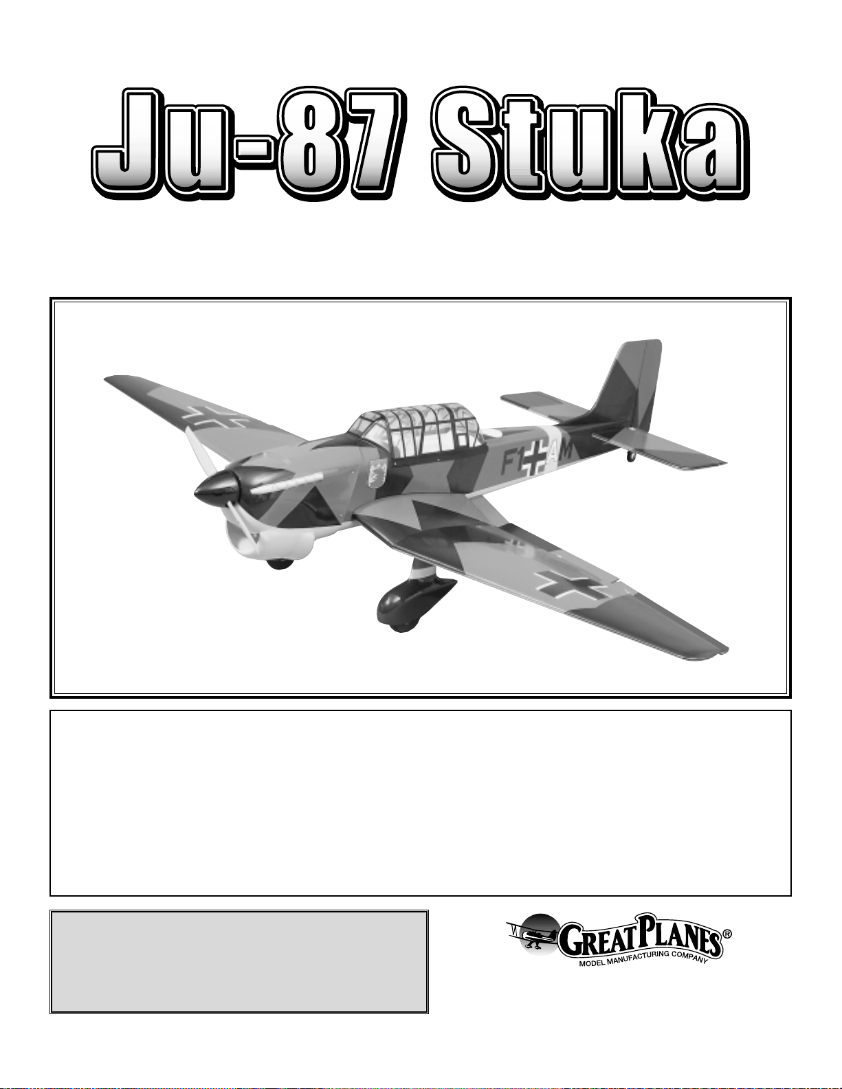
A. R. F.
Almost Ready to Fly
Wingspan: 70" [1780mm]
Wing area: 770 sq in [49.6 dm2]
Weight: 8 lbs [3630g]
Wing loading: 24 oz/sq ft [73 g/dm2]
Length: 55" [1400mm]
Radio: 4–7 ch (w/5–7 standard servos)
Engine: .61–75 cu. in. two-stroke [10–12.5cc]
.91 cu. in. four-stroke [15cc]
Page 2
INTRODUCTION.....................................................................2
SAFETY PRECAUTIONS.......................................................2
DECISIONSYOU MUST MAKE .............................................3
Radio Equipment..............................................................3
Engine Recommendations ...............................................3
ADDITIONAL ITEMS REQUIRED..........................................3
Hardware & Accessories..................................................3
Adhesives & Building Supplies.........................................3
Optional Supplies & Tools ................................................3
IMPORTANT BUILDING NOTES............................................4
COMMON ABBREVIATIONS.................................................4
ORDERING REPLACEMENT PARTS....................................4
KIT CONTENTS......................................................................5
METRIC/INCH RULER ...........................................................5
WING ASSEMBLY..................................................................6
FUSELAGE ASSEMBLY ......................................................12
INSTALL THE HINGES.........................................................14
INSTALL THE ENGINE.........................................................16
INSTALL THE LANDING GEAR...........................................16
INSTALL THE FUEL TANK...................................................18
INSTALL THE RADIO, PUSHRODS &
CONTROL HORNS...............................................................18
INSTALL THE FLAP & AILERON SERVOS ........................21
INSTALL THE RADIO SYSTEM...........................................24
INSTALL THE COWL............................................................25
FINISH & INSTALL THE CANOPY ......................................26
APPLY THE DECALS...........................................................27
GET THE MODEL READYTO FLY ......................................27
Check the Control Directions..........................................27
Set the Control Throws...................................................27
Balance the Model (C.G.)...............................................28
Balance the Model Laterally...........................................28
PREFLIGHT..........................................................................29
Identify Your Model.........................................................29
Charge the Batteries ......................................................29
Balance the Propellers...................................................29
Ground Check ................................................................29
Range Check..................................................................29
ENGINE SAFETY PRECAUTIONS......................................29
AMA SAFETY CODE (excerpt) ...........................................30
CHECK LIST.........................................................................30
FLYING..................................................................................31
Fuel Mixture Adjustments...............................................31
Takeoff............................................................................31
Flight...............................................................................31
Landing...........................................................................32
IDENTIFICATION TAG..........................................................32
For the latest technical updates or manual corrections for
the Stuka, visit the web site listed below and select the
Great Planes Stuka ARF. A “tech notice” box will appear in
the upper left corner of the page if there is new technical
information or changes to this kit.
http://www.greatplanes.com/airplanes/index.html
1. Your Stuka should not be considered a toy, but rather a
sophisticated, working model that functions very much like
a full-size airplane. Because of its performance capabilities,
the Stuka, if not assembled and operated correctly, could
possibly cause injury to yourself or spectators and damage
property.
2. You must assemble the model according to the
instructions. Do not alter or modify the model, as doing so
may result in an unsafe or unflyable model. In a few cases
the instructions may differ slightly from the photos. In those
instances the written instructions should be considered as
correct.
3.You must take time to build straight, true and strong.
4. You must use an R/C radio system that is in first-class
condition, and a correctly sized engine and components
(fuel tank, wheels, etc.) throughout the building process.
5.You must properly install all R/C and other components so
that the model operates properly on the ground and in
the air.
6.You must check the operation of the model before every
flight to insure that all equipment is operating and that the
model has remained structurally sound. Be sure to check
clevises or other connectors often and replace them if they
show any signs of wear or fatigue.
7. If you are not already an experienced R/C pilot, you
should fly the model only with the help of a competent,
experienced R/C pilot.
Remember: Take your time and follow the instructions
to end up with a well-built model that is straight
and true.
If you have not flown this type of model before, we
recommend that you get the assistance of an experienced
pilot in your R/C club for your first flights. If you’re not a
member of a club, your local hobby shop has information
about clubs in your area whose membership includes
experienced pilots.
We, as the kit manufacturer, provide you with a top quality
kit and instructions, but ultimately the quality and flyability
of your finished model depends on how you build it;
therefore, we cannot in any way guarantee the
performance of your completed model, and no
representations are expressed or implied as to the
performance or safety of your completed model.
PROTECT YOUR MODEL,YOURSELF
& OTHERS...FOLLOW THESE
IMPORTANT SAFETY PRECAUTIONS
INTRODUCTION
TABLE OF CONTENTS
2
Page 3
In addition to joining an R/C club, we strongly recommend
you join the AMA (Academy of Model Aeronautics). AMA
membership is required to fly at AMA sanctioned clubs.
There are over 2,500 AMA chartered clubs across the
country. Among other benefits, the AMA provides insurance
to its members who fly at sanctioned sites and events.
Additionally, training programs and instructors are available
at AMA club sites to help you get started the right way.
Contact the AMA at the address or toll-free phone
number below:
Academy of Model Aeronautics
5151 East Memorial Drive
Muncie, IN 47302-9252
Tele. (800) 435-9262
Fax (765) 741-0057
Or via the Internet at:
http://www.modelaircraft.org
This is a partial list of items required to finish the Stuka that
may require planning or decision-making before starting
to build.
In addition to the items listed in the “Decisions You Must
Make” section, following is the list of hardware and
accessories required to finish the Stuka. Order numbers are
provided in parentheses.
❏ Engine –O.S.
®
61 FX (OSMG0561), SuperTigre®G-
61
(SUPG0181), O.S. 91 II Surpass
™
(OSMG0896) or the
SuperTigre G-75 (SUPG0205)
❏ Radio – Futaba
®
6XAS (FUTK30**)
❏ Propellers – Follow engine manufacturer’ s
recommendation
❏
Fuel line – 12" medium silicone fuel line
❏
Easy Fueler™fuel filling valve for glow fuel (GPMQ4160)
In addition to common household tools and hobby tools, this
is the “short list” of the most important items required to
build the Stuka.
Great Planes Pro™CA and Epoxy glue are
recommended.
❏
1/2 oz. Thin Pro CA (GPMR6001)
❏
1/2 oz. Medium Pro CA+ (GPMR6007)
❏
6-Minute Epoxy (GPMR6045)
❏
30-Minute Epoxy (GPMR6047)
❏
Hobby knife (HCAR0105)
❏
#11 blades (HCAR0211)
❏
Small T-pins (HCAR5100)
❏
Builder’s triangle (HCAR0480)
❏
Electric drill
❏
Small phillips and flat blade screwdrivers (HCAR1040)
❏
Pliers with wire cutter (HCAR0630)
❏
Silicone sealant
Here is a list of optional tools mentioned in the manual that
will help you build the Stuka.
❏
Great Planes CG Machine™(GPMR2400)
❏
Top Flite®Precision Magnetic Prop Balancer
™
(TOPQ5700)
❏
Straightedge with scale (HCAR0475)
❏
Masking tape (TOPR8018)
❏
CA Applicator tips (GPMR6033)
❏
CA Debonder (GPMR6039)
❏
CA Accelerator (GPMR6034)
❏
Epoxy brushes (GPMR8060)
❏
Mixing sticks (GPMR8055)
❏
Threadlocker (GPMR6060)
❏
Rubbing alcohol (for epoxy clean up)
❏
Builder’sTriangle Set (HCAR0480) (for fin alignment)
❏
Felt-Tip marker (TOPQ2510)
❏
Drill bits used:1/16", 17/64" (or 1/4"), #48 (or 5/64"), #29
(or 9/64") drill and 6-32 tap
❏
Great Planes 8-32 tap and drill set (GPMR8103)
❏
Curved Tip Canopy Scissors for trimming plastic parts
(HCAR0667)
❏
Dead Center™Engine Mount Hole Locator (GPMR8130)
❏
Great Planes AccuThrow™Deflection Gauge (for
measuring control throws, GPMR2405)
Optional Supplies & Tools
Adhesives & Building Supplies
Hardware and Accessories
ADDITIONAL ITEMS REQUIRED
Radio Equipment
The Stuka will require a good 4–7 channel radio system
or greater with 7 servos. The servos need to have a
minimum of 40 oz. of torque. In addition you will need two
12" aileron extensions and two 6" aileron extensions and
two “Y” connectors.
Engine Recommendations
The recommended engine size range for the Stuka is a
.61–.75 two-stroke or a .91 four-stroke. If an engine in the
upper end of the size range is used, remember that this is
a scale model that is intended to fly at scale-like speeds,
so throttle management should be practiced.
DECISIONSYOU MUST MAKE
3
Page 4
To order replacement parts for the Great Planes Stuka ARF, use the order numbers in the Replacement Parts List that
follows. Replacement parts are available only as listed. Not all parts are available separately (an aileron cannot be
purchased separately, but is only available with the wing kit). Replacement parts are not available from Product Support,
but can be purchased from hobby shops or mail order/Internet order firms. Hardware items (screws, nuts, bolts) are also
available from these outlets. If you need assistance locating a dealer to purchase parts, visit www.greatplanes.com and
click on “Where to Buy.” If this kit is missing parts, contact Great Planes Product Support.
Replacement Parts List
Or
der Number Description HowtoPurchase
Missing pieces ......................Contact Product Support
Instruction manual.................Contact Product Support
Full-size plans .......................Not available
GPMA2220......................................Wing Kit
GPMA2221......................................Fuse Kit
GPMA2222......................................Tail Set Contact Your Hobby
GPMA2223......................................Cowl Supplier to Purchase
GPMA2224......................................Canopy These Items
GPMA2225......................................Landing Gear
GPMA2226......................................Wheel Pants
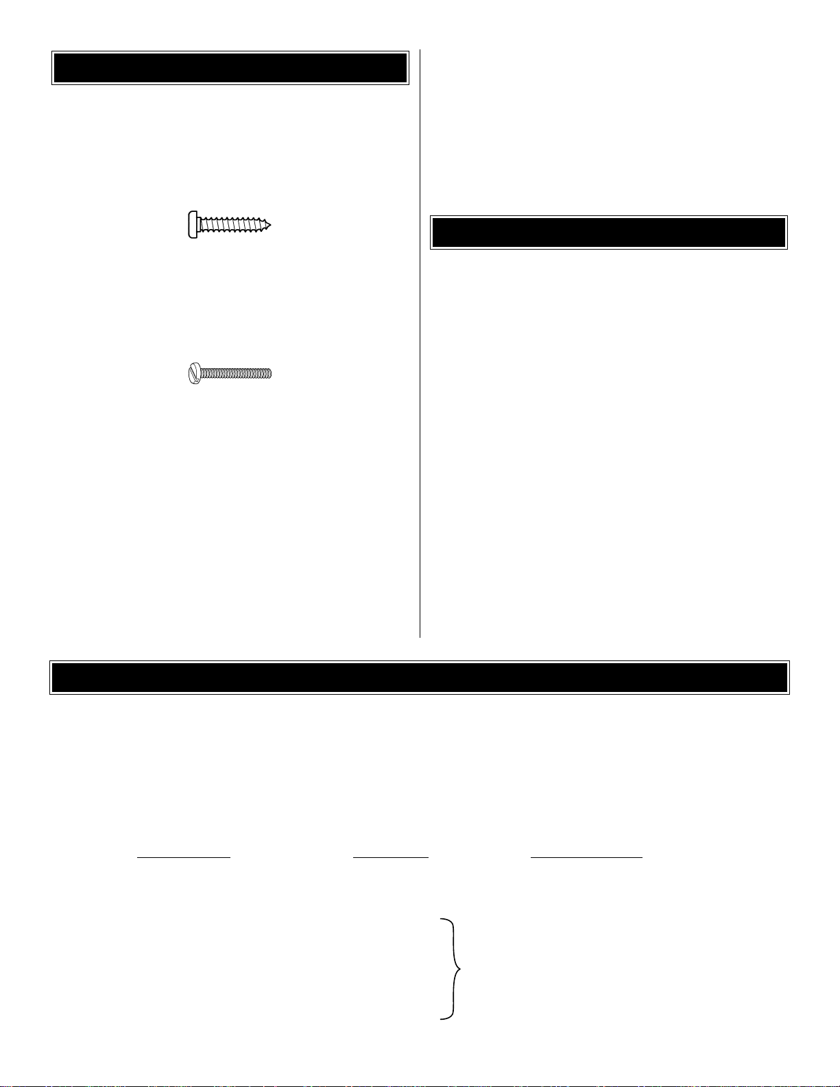
• There are two types of screws used in this kit:
Sheet metal screws are designated by a number and a
length. For example #6 x 3/4".
This is a number six screw that is 3/4" long.
Machine screws are designated by a number, threads per
inch, and a length. For example 4-40 x 3/4".
This is a number four screw that is 3/4" long with forty
threads per inch.
• When you see the term
test fit
in the instructions, it means
that you should first position the part on the assembly
without using any glue, then slightly modify or custom fit the
part as necessary for the best fit.
• Whenever the term
glue
is written you should rely upon
your experience to decide what type of glue to use.When a
specific type of adhesive works best for that step, the
instructions will make a recommendation.
• Whenever just
epoxy
is specified you may use
either
30-minute (or45-minute) epoxyor6-minute epoxy. When
30-minute epoxy is specified it is highly recommended that
you use only 30-minute (or 45-minute) epoxy, because you
will need the working time and/or the additional strength.
• Photos and sketches are placed before the step they
refer to. Frequently you can study photos in following steps
to get another view of the same parts.
Fuse = Fuselage
Stab = Stabilizer
Fin = Vertical Fin
LE = Leading Edge
TE = Trailing Edge
LG = Landing Gear
Ply=Plywood
" = Inches
COMMON ABBREVIATIONS
IMPORTANT BUILDING NOTES
4
ORDERING REPLACEMENT PARTS
................
Page 5
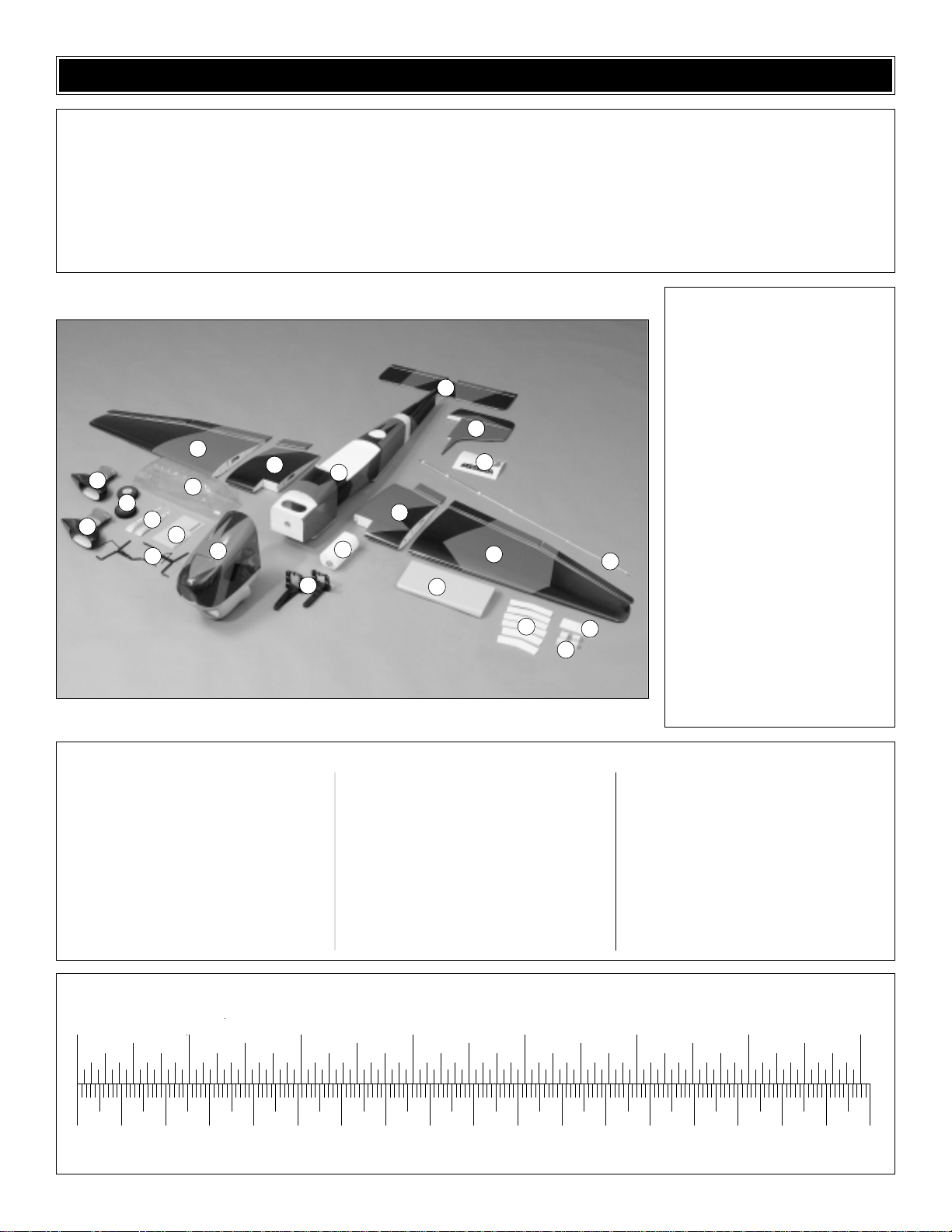
5
1 L&R Wing with Ailerons & Flap
2 Inner Wing with Flaps
3 Fuselage
4 Stab with Elevators
5 Fin with Rudder
6 Painted Cowl
7 Canopy
8 Painted Wheel Pants (2)
9 Painted Aluminum Landing
Gear (2)
10 Wing Joiners
11 Fuel Tank with Hardware
12 Wing Fairing
13 Aileron Servo Covers
14 Engine Mount
15 3" Wheel (2)
16 Wing Bolt Plate
17 Pushrods
18 Decals
19 Exhaust Stacks
20 Aileron Mounting Blocks (4)
(1) 3" Black spinner
(2) Bolt-on axles
(4) 2.5mm ID brass tube x 15mm (flap
mechanism)
(2) 2.5mm Steel pin x 25mm (flap mechanism)
(16) Nylon flap/aileron hinges
(1) 1-1/4" Tail wheel
(3) Large control horn
(4) Small control horn
(2) Nylon 1/4-20 bolt
(8) Nylon clevis
(8) Nylon landing gear straps
(1) 2" x 9" Hinge strip
(7) Faslinks
(8) Silicone clevis retainer
(56) #2 x 3/8" Sheet metal screw (landing gear
straps,
aileron covers, canopy, flap/aileron hinges)
(8) #2 x 1/2" Sheet metal screw (wheel pants)
(16) #2 Washers
(4) 5/32" Wheel collar
(6) 6-32 x 1/4" Socket head cap screw (for wheel
collars and axles)
(1) 3/32" Wheel collar (for tail wheel)
(1) 4-40 Set screw (for tail wheel collar)
(6) #4 x 3/8" Sheet metal screw (mounting the
cowl)
(6) #4 Washers (mounting the cowl)
(1) Wire tail wheel
(4) 1" x 1" Servo mounting tape (for mounting the
aileron servos)
(3) 2-56 x 36" Pushrod
(1) 2-56 x 17-1/2" Pushrod
(4) 2-56 x 6" Pushrod
(4) 8-32 x 1" Socket head cap screw (engine
mount)
(4) 8-32 x 3/4" Socket head cap screw (mounting
the engine)
(8) #8 Washers
Kit Contents
(Photographed)
Kit Contents (Not Photographed)
0" 1" 2" 3" 4" 5" 6" 7"
0 10 20 30 40 50 60 70 80 90 100 110 120 130 140 150 160 170 180
Inch Scale
Metric Scale
To convert inches to millimeters, multiply inches by 25.4
Before starting to build, use the Kit Contents list to take an inventory of your kit to make sure it is complete, and inspect
the parts to make sure they are of acceptable quality. If any parts are missing or are not of acceptable quality, or if you
need assistance with assembly, contact Great Planes Product Support. When reporting defective or missing parts, use
the part names exactly as they are written in the Kit Contents list on this page.
Great Planes Product Support:
Phone: (217) 398-8970
Fax: (217) 398-7721
E-mail: airsupport@greatplanes.com
KIT CONTENTS
10
11
16
20
17
18
12
13
14
15
19
1
7
8
8
9
2
3
4
5
6
2
1
Page 6
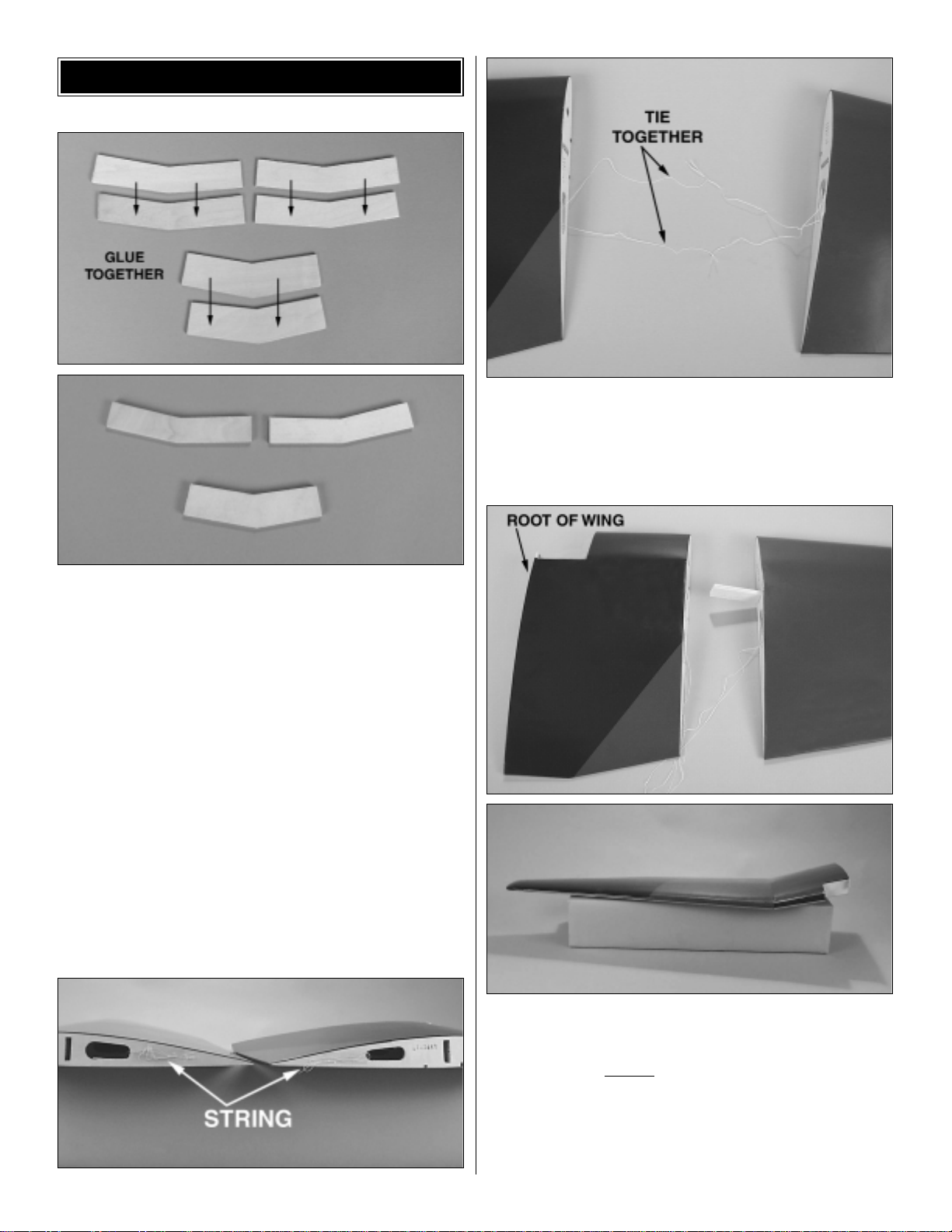
❏ 1. Locate the two plywood center wing joiners and four
plywood outer wing joiners. Using 6-minute epoxy, glue
two plywood center wing joiners together forming one 1/4"
[6mm] center wing joiner. Do the same to the outer wing
joiners, making two 1/4" [6mm] outer wing joiners.
❏❏2. Locate the right wing panel and the right inner
wing panel. At the root of each wing panel where the two
panels join are two strings. Tie the strings together. The
strings will be used for pulling the servo wires through the
wing when the radio installation takes place.
❏❏3. Test fit the outer wing joiner to the wing panel and
the inner wing panel. Be sure the wing panel is assembled
to the correct end of the inner wing panel. The end of the
inner wing panel without
the cut-out is the end of the panel
that is glued to the wing panel.Be sure when fitting the joiner
that the bend in the wing is going the proper direction (see
photo). When you are satisfied that everything fits properly,
use 30-minute epoxy to join the two wing sections and glue
the joiner into the wing box in the wings (Be sure to use
WING ASSEMBLY
6
Page 7
ample glue to coat the wing box where the joiner goes into
it) and apply epoxy to both wing ribs.
❏❏4. Hold the wing panel and the inner wing panel
together with masking tape until the glue fully cures. Any
excess epoxy that squeezes out of the wing joint can be
cleaned away with rubbing alcohol as long as the glue has
not cured.
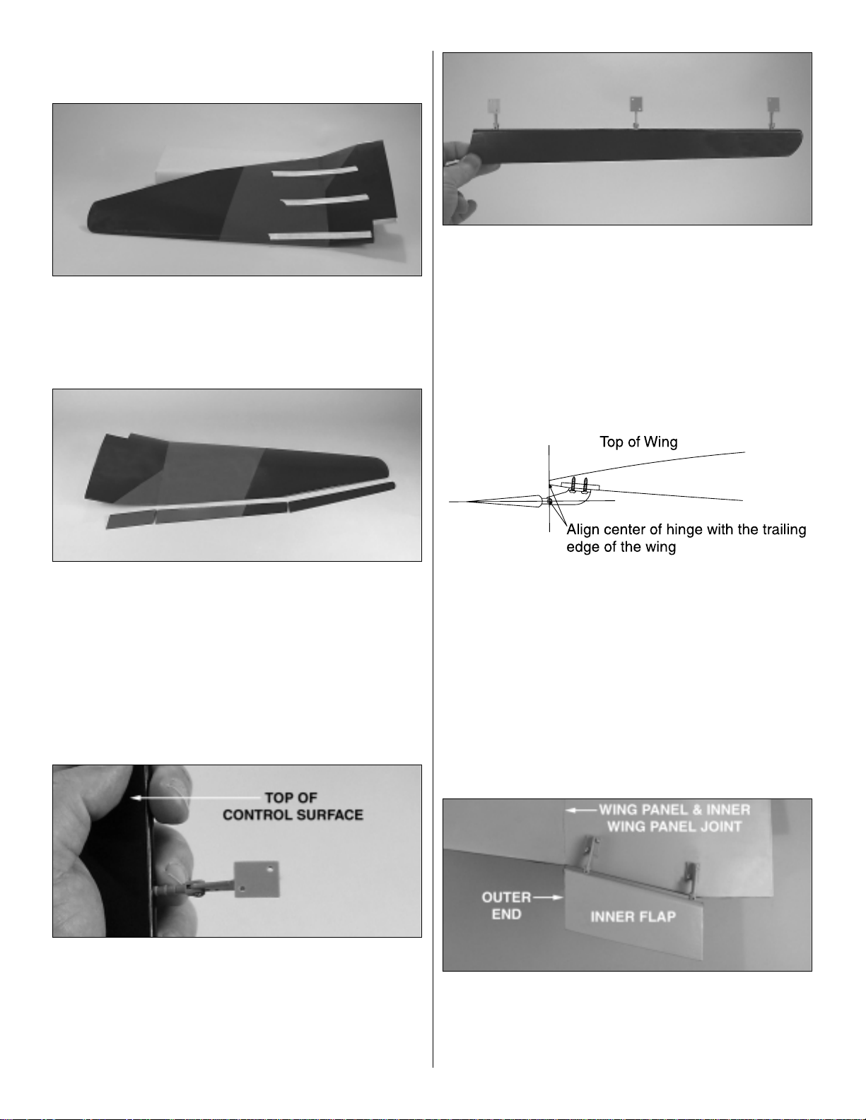
❏❏5. Locate the right aileron, flap and inner flap. It is
easy to determine the right control surfaces from the left by
matching the covering on the top of the wing with the
covering on the top of the control surfaces.
❏❏6. On the leading edge of the aileron, flap and inner
flap are pre-drilled holes for the hinges. Cut the covering
away over the three holes in the leading edge of the aileron,
three holes in the leading edge of the flap and two holes in
the leading edge of the inner flap.
❏❏7.Test fit the hinges into each of the holes.Make note
that when the hinges are properly installed the bottom of the
hinge plate will face the top of the control surface.
❏❏8. Apply a small drop of oil or a dab of petroleum jelly
onto each of the hinge joints. This will prevent the glue from
getting into the hinge joint when installing the hinges.
❏❏9. After each hinge has been lubricated, glue each
hinge into the pre-drilled holes in the aileron and both flaps
with 6-minute epoxy. Be sure that each hinge has the plate
facing the top of the control surface as shown in the above
photograph of the aileron.
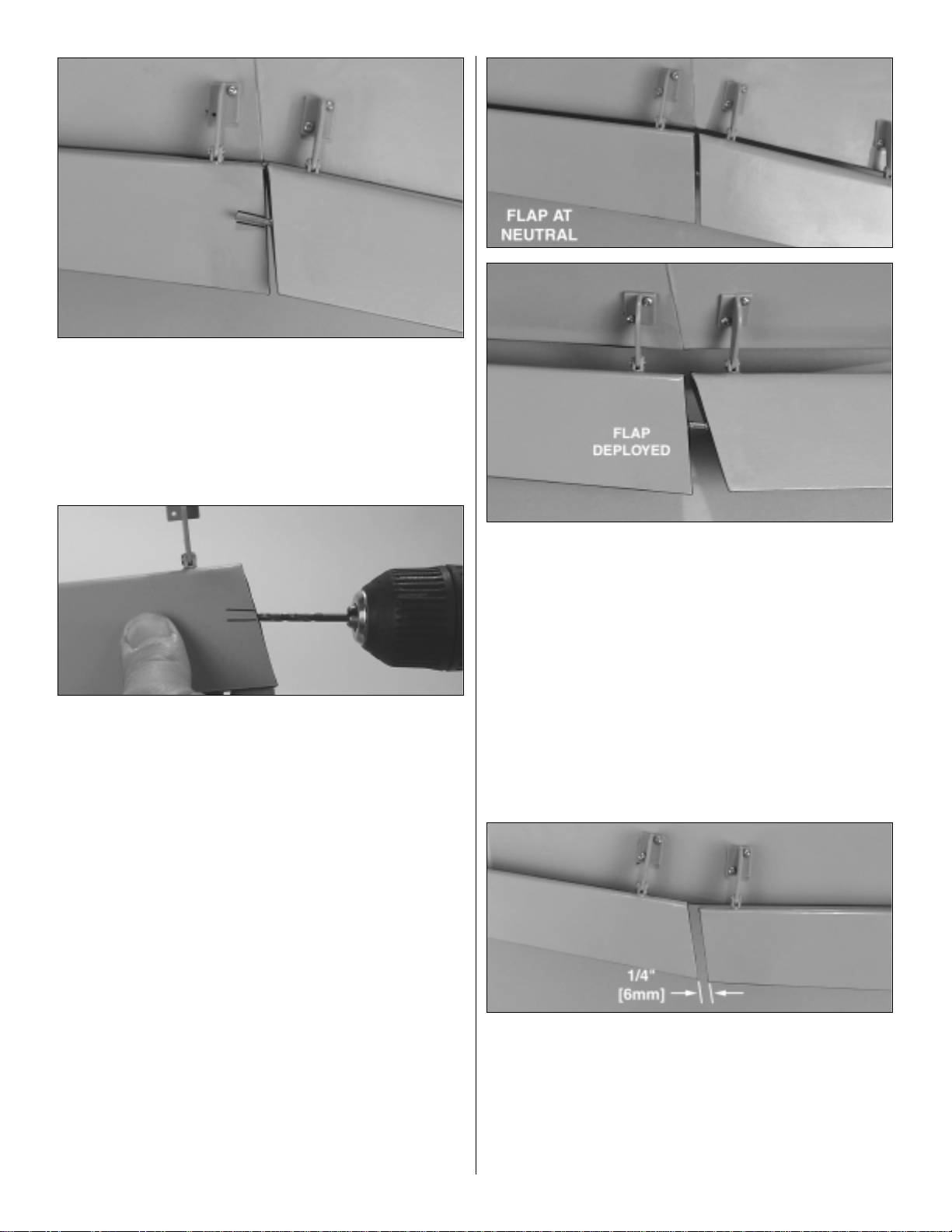
❏❏10.Before mounting the control surfaces to the surface
of the wing it is important to understand the positioning of
the hinges to the wing. When mounted properly the aileron
and flap are below the trailing edge of the wing and the
hinge line should be even with the trailing edge of the wing.
Study the illustration to be sure you understand exactly how
they will be mounted.
❏❏11.Begin the installation of the control surface with the
inner flap.When it is installed it will be positioned as shown
in the photograph.Do not install the inner flap yet.Reference
the photograph to determine which end of your inner flap is
the outboard end.
7
Page 8
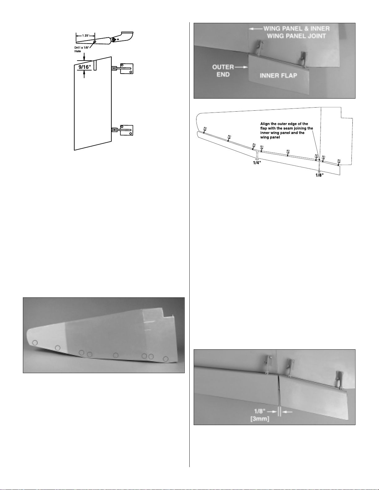
❏❏12. On the outboard end of the inner flap draw a line
1-1/4" [31mm] from the trailing edge of the inner flap.On this
line mark the center of the flap and carefully drill a 1/8"
[3mm] hole on this mark into the flap 9/16" [14.3mm],
making sure you are centered in the flap and that the hole is
drilled parallel to the leading edge of the flap.
❏❏13. Locate one of the 3/32" x 9/16" [2.5mm x 15mm]
brass tubes. Insert it half way into the hole you drilled in the
end of the inner flap.Place a small drop of medium CA glue
onto the
outside
of the tube.Then press the tube all the way
into the inner flap.
Be sure that CA glue does not get into the
inside of the brass tube.
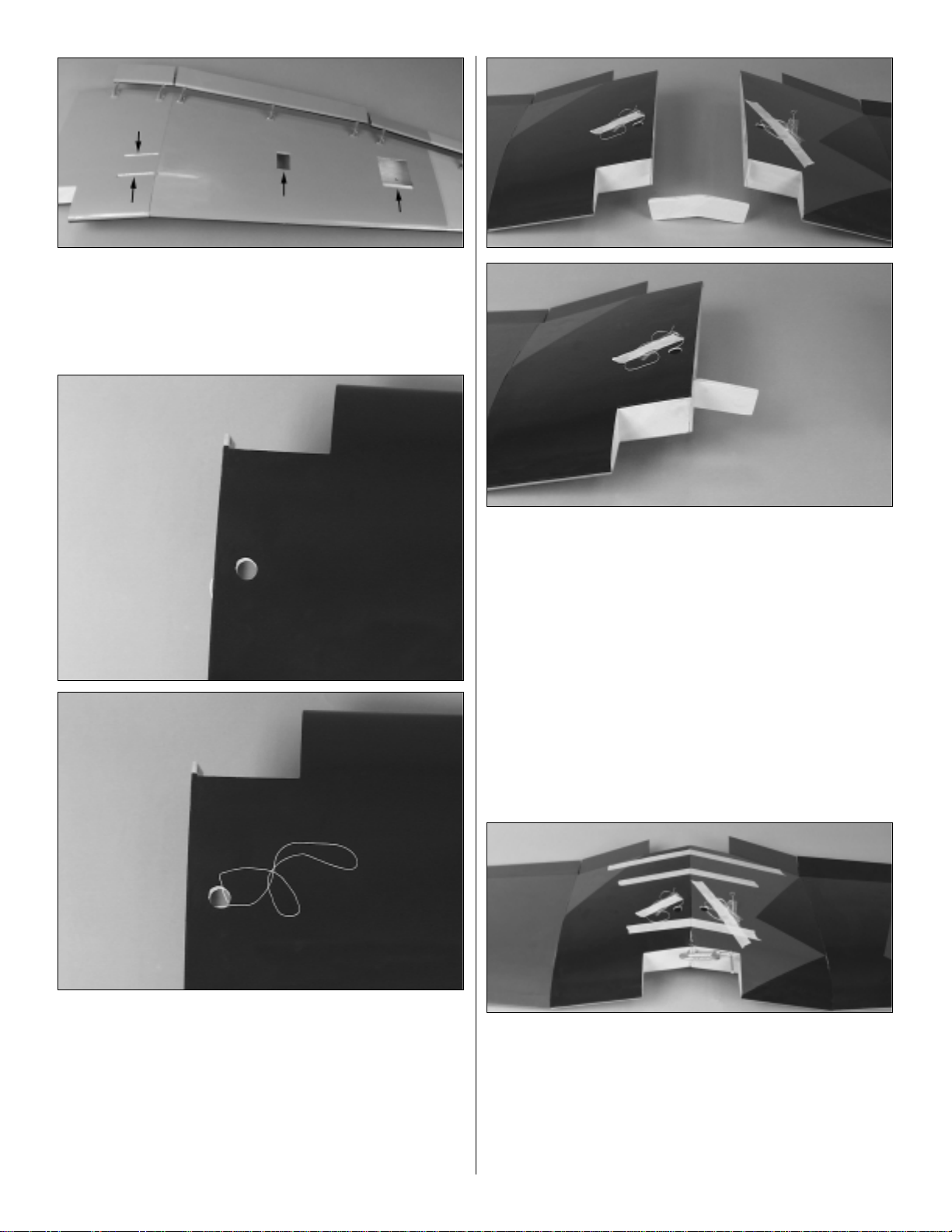
❏❏14. You are now going to proceed with installation of
the flap and ailerons. Before installing the hinges you need
to take a close look at the bottom of the wing.If you hold the
wing and look across the face of the bottom of the wing at
the trailing edge, you should be able to see the outline of
eight circular wooden mounts. Refer to the above
photograph. (For easy reference we have drawn the circles
onto the covering. This should help you locate each of the
mounts.) These mounts are what you will be screwing the
hinge plates to as we proceed with installing the aileron and
flaps. As you work through the installation of the flap and
aileron be sure that you are screwing into these wood
blocks.
❏❏15. Position the inner flap onto the wing. When doing
this the inner flap must line up with the joint where the inner
wing panel and the wing are joined. The center of the hinge
must also be in line with the trailing edge of the wing as
shown in the sketch at step 10. Once you are satisfied with
the position of the inner flap, mark the location for the
mounting screws with a felt-tip marker onto the wing. Drill a
1/16" [1.5mm] hole through each of these marks into the
wing. BE CAREFUL NOT TO DRILL THROUGH THE TOP
OF THE WING! Once you have the holes drilled, install the
inner flap with four #2 x 3/8" [9.5mm] screws.
❏❏16.Temporarily mount the main flap to the wing with a
#2 x 3/8" [9.5mm] screw in the inboard and outboard hinge.
The inside end of the flap must be located 1/8" [3mm] from
the outer end of the inner flap. (Refer to the sketch in
step 15).
8
Page 9
❏❏17.Insert the 2.5 x 25mm steel pin into the brass tube
you installed in the inner flap.Position the inner flap with the
steel pin so that the steel pin is resting on top of the flap.
Draw a line on each side of the steel pin onto the flap.
❏❏18. Drill a 1/8" [3mm] hole into the center of the end of
the flap as you did for the inner flap. Be sure as you drill the
hole that it is parallel to and centered between the lines you
have drawn on the flap.
❏❏19. Locate another 2.5mm x 15mm brass tube. Insert
it half way into the hole you drilled in the end of the flap.
Place a small drop of medium CA glue onto the
outside
of
the tube. Then press the tube all the way into the inner flap.
Be sure that CA glue does not get into the inside of the
brass tube.
❏❏20. Install the steel pin into the brass tube in the inner
flap.Then slide the flap onto the steel pin extending from the
inner flap. Mark the location for the mounting screws with a
felt-tip marker onto the wing. Drill a 1/16" [1.5mm] hole
through each of these marks into the wing. BE CAREFUL
NOTTO DRILL THROUGH THE TOP OF THE WING! Once
you have the holes drilled, install the flap with six #2 x 3/8"
[9.5mm] screws.
❏❏21. With the flap and inner flap mounted to the wing
you can now see how the flap and inner flap are tied
together by the steel pin and how they will move together
when the flaps are deployed. (If there is any binding
between the inner flap and the flap, you may be able to get
a smoother operation if you put a slight bend in the steel pin.
This should only be necessary if you do not get the hole for
the brass tube in perfect alignment.)
❏❏22. Position the inner end of the aileron 1/4" [6mm]
from the outer end of the flap (refer to the sketch in step 15).
Install the aileron by marking the location for the mounting
screws with a felt-tip marker onto the wing. Drill a 1/16"
[1.5mm] hole through each of these marks into the wing. BE
CAREFUL NOT TO DRILL THROUGH THE TOP OF THE
WING! Once you have the holes drilled, install the aileron
with six #2 x 3/8" [9.5mm] screws.
9
Page 10
❏❏23. On the bottom of the wing, cut away the covering
from the two servo bays and the landing gear mounting rails.
❏❏24. Cut away the covering in the top of the wing to
reveal the holes that the servo leads come through. After
cutting the hole, feed the string from inside of the wing
through the hole. This will allow you to pull the servo leads
through the wing after the two wing halves are joined.
❏ 25. Repeat steps 2 to 24 for the left wing panel.
❏ 26. Locate the plywood center wing joiner. Test fit it into
the right and left wing halves. When fitting it into the wing,
make sure that the joiner angles downward.
❏ 27. When you are satisfied that the two wing halves fit
well together, apply a liberal amount of 30-minute epoxy to
the joiner, the joiner box and the wing root ribs. Insert the
wing joiner into one of the wings and then install the
opposite wing onto the other end of the wing joiner. Put a
clamp onto the tab that extends forward from the center of
the wing and use masking tape to hold the wings together
while the glue is curing.
10
Page 11

❏28.After the glue has cured, cut awaythe covering on the
top and bottom of the wing at the trailing edge of the wing to
expose the two holes for the nylon wing bolts to pass
through.
❏ 29. Locate the wing fairing. Cut away the covering to
expose the two holes for the wing bolts.
❏30. Mount the wing onto the fuselage with the nylon wing
bolts. Set the wing fairing onto the wing in line with the
fuselage. Draw a line on each side of fairing. Then remove
the fairing and the wing.
❏ 31. Cut away a 1/2" [13mm] strip of covering inside each
of the lines you have drawn. Be careful not to cut into the
surface of the wing sheeting. This could weaken the
structure of the wing.
❏ 32. Locate the plywood wing bolt plate. Flex it to fit it to
the
trailing edge of the wing. Draw a line on the covering to
mark the location of the wing bolt plate. Then cut the
covering away and glue the wing bolt plate to the wing with
6-minute epoxy.
❏ 33. After the glue has cured, turn the wing over. Use a
17/64" [6.7mm] drill bit to drill through the holes from the top
of the wing, drilling through the wing bolt plate.
11
Page 12

❏ 34. Glue the wing fairing in place on the wing with
6-minute epoxy.
❏ 1. Cut away the covering from the rear of the fuselage to
reveal the slots for the fin, stab and the holes for the
pushrods. There are two holes for the pushrods on the left
side of the fuselage and one hole on the right side.
❏ 2. Bolt the wing onto the fuselage.
❏ 3. Slide the horizontal stabilizer into the slot in the
fuselage.
❏ 4. Measure from the end of the stab to each wing tip and
from the center of the fuselage out to the end of the stab as
shown in the sketch.
❏ 5. Once you have the stab properly positioned, mark the
outline of the fuselage on the top and bottom of the stab.
Removethe stab from the fuse.Use a sharp #11 hobby knife
or use the Expert Tip that follows to cut the covering from
the stab along the lines you marked. Use care to cut only
into the covering and not into the wood.
FUSELAGE ASSEMBLY
12
Page 13

❏ 6. Place the stab back into the fuselage. Stand back
approximately10' [3m] and view your plane from the rear.Be
sure the stab is straight in relation to the wing as shown in
the sketch. If it is not straight, sand a bit of the wood awayin
the stab saddle on the side that is high until the stab is
straight.
❏7. Glue the stab in place with 6-minute epoxy, checking to
be sure that it is properly positioned before the glue has
cured.
❏ 8. Position the fin in the slot at the rear of the fuselage.
Mark the outline of the fuselage onto the fin. Then cut the
covering away using the same technique used for the stab.
❏9.Test fit the fin into the slot. Use a builders triangle to be
sure that the fin is 90 degrees to the stab. When you are
satisfied with the fit, glue the fin in place with 6-minute
epoxy.
How to cut covering from balsa.
Use a soldering iron to cut the covering from the stab.The
tip of the soldering iron doesn’t haveto be sharp, but a fine
tip does work best. Allow the iron to heat fully. Use a
straightedge to guide the soldering iron at a rate that will
just melt the covering and not burn into the wood. The
hotter the soldering iron, the faster it must travel to melt a
fine cut. Peel off the covering (see the photo at step 11).
13
Page 14

❏ 1. The hinge slots for the elevators and the rudder are
pre-cut in the trailing edge of the stab and fin as well as the
leading edge of the elevator and rudder.Using a #11 hobby
knife, run the blade in each of the three hinge slots in each
control surface.
❏2.Drill a 3/32" [2.4mm] hole in the center of the hinge slot.
This will allow the glue to fully wick into the hinge.
❏ 3. Cut 9 hinges 3/4" x 1" [19 x 25mm] from the hinge
material. Cut the material as shown.Cut the corners of each
hinge as shown in the second illustration. This will make it
easier when installing the hinges.
❏ 4. Install a pin into the center of three hinges, then install
one hinge in each of the slots in one of the elevator halves.
Install the hinge until the pin is touching the leading edge of
the elevator. Install the opposite end of the hinges into the
trailing edge of the stab.
❏ 5. Remove the pins.Then apply 6 drops of thin CA to the
center of the hinge on both sides of the hinge.
❏ 6. Repeat the procedure for the other elevator half.
❏ 7. From the bottom of the rudder measure up 1" [25mm]
and make a mark.
INSTALL THE HINGES
14
ASSEMBLE, THEN APPLY 6 DROPS
OF THIN CA TO CENTER
OF HINGE, ON BOTH SIDES
DRILL A 3/32" HOLE
1/2" DEEP, IN CENTER
OF HINGE SLOT
1"
[25mm]
1"
[25mm]
3/4"
[19mm]
TEMPORARY PIN
TO KEEP HINGE
CENTERED
Page 15

❏ 8. Drill a 5/32" [4mm] hole in the leading edge of the
elevator 1/2" [13mm] deep at the 1" [25mm] mark.
❏ 9. Locate the tail wheel wire and install it into the hole
you just drilled.On the leading edge of the rudder, cut a slot
the width of the nylon bearing. Remove the tail wheel wire
and cut the slot to a depth that allows the bearing to rest in
the leading edge of the rudder.Fuelproof the slot with a thin
coat of 6-minute epoxy. After the epoxy cures, re-install the
tail wheel wire into the rudder.
❏ 10. Hold the rudder up to the fin. Mark the location of the
nylon bearing from the tail wheel wire.
❏11.Cut a slot in the end of the fuselage from the mark you
made to the bottom of the fuselage. Insert the nylon bearing
into the slot. When you are satisfied with the fit, glue the
nylon bearing to the fuselage with 6-minute epoxy. Apply a
light coat of petroleum jelly to the wire and the nylon bearing
to prevent glue from getting into the nylon bearing.
❏ 12. Install the hinges into the rudder using the same
procedure used for the elevator.Slide the hinges into the fin,
making sure that the tail wheel wire is inserted into the hole
you drilled in the leading edge of the rudder.When you are
satisfied with the fit of the rudder to the fin, apply 6 drops of
thin CA glue to each of the hinges.
❏ 13. Install the tail wheel onto the tail wheel wire. Hold it in
place with the 3/32" wheel collar and the 4-40 set screw.
15
Page 16

❏ 1. Locate the left and right halves of the engine mount.
Cut off the “spreader bar” from each half of the engine
mount.
❏2. Install the engine mount to the firewall.Screw four 8-32
x 1" socket head cap screws and four #8 washers through
the engine mount into the pre-installed 8-32 blind nuts in the
firewall.
❏ 3. Adjust the width of the engine mount for your engine.
Then position the engine onto the engine mount so that the
distance from the firewall to the front of the thrust washer is
4-3/4" [121mm].
❏ 4. Once you have the engine properly positioned on the
engine mount, mark the location of the engine mounting
holes on the rails of the engine mount. A great tool for doing
this is the Great Planes Dead Center™Tool (GPMR8130).It’s
fast, easy and accurate!
❏ 5. Once you have the locations for the mounting holes
marked on the engine mount, drill a 7/64" [2.8mm] hole into
each of the four marks. After drilling the holes tap each of
them with a 6-32 tap.
❏ 6. Mount the engine to the engine mount with four 6-32 x
3/4" socket head cap screws and four #6 washers.
❏❏1. Locate the left and right landing gear. Test fit the
right landing gear wire into the slots in the right wing.
INSTALL THE LANDING GEAR
INSTALL THE ENGINE
16
Page 17

❏❏2. Install four nylon landing gear straps to hold the
landing gear wire to the wing.Position the nylon straps using
the dimensions shown in the photograph. Once positioned,
drill a 1/16" [1.5mm] pilot hole through the strap and into the
hardwood mounting block in the wing. Install the straps with
eight #2 x 3/8" [9.5mm] sheet metal screws.
❏❏3. Position a wheel pant over the landing gear wire on
the wing. Do not attach it yet.
❏❏4. Locate a wheel, axle and 4-40 socket head cap
screw. Install the socket head cap screw into the axle.
❏❏5. Slide the wheel and axle onto the landing gear wire.
Position the axle and wheel as shown. Position the wheel
pant so that the wheel is centered in the pant. Mark the
location of the wheel pant on the wing with a felt-tip marker.
❏❏6. Mark a location onto the wheel pant for two screws
on each side. These marks will be the drilling location so
make these marks over the hardwood blocks that the nylon
landing gear straps are screwed into.Once you are satisfied
with the location, drill a 1/16" hole through the mark and into
the wing. Screw the pant in place with four #2 x 1/2" [13mm]
machine screws and four #2 washers.
❏❏7.When you are satisfied with the position of the axle
on the landing gear wire, file a flat spot on the landing gear
17
Page 18

wire for the set screw to tighten onto. This flat spot will also
prevent the axle from slipping on the landing gear wire. File
a flat spot on the axle for the wheel collar too. Install the
wheel and one 5/32" [4mm] wheel collar onto the axle and
insert the axle onto the landing gear wire.Then tighten the
set screws to the axle and wheel collar.
❏ 8. Repeat this procedure for the left landing gear.
❏ 1. Assemble the fuel tank as shown in the sketch. When
tightening the center screw, be sure not to overtighten it.You
just want it snug enough to pull the rubber stopper tight
against the tank.
❏ 2. Install silicone fuel tubing (not included in the kit) onto
the aluminum tubes from the fuel tank.The line with the fuel
clunk will feed to the fuel inlet at the needle valve and the
other will attach to the pressure tap on the muffler. For our
installation we chose to use an external fill valve. If you
choose to do this as well, follow the instructions with the fuel
valve.Should you choose not to install a fuel filler valve, you
can fill the fuel tank by removing the fuel line to the
carburetor and filling through it. However, depending on how
you cut out the cowling to accommodate the engine, the
cowling may make it difficult to access the carburetor. You
can also install a third line to the tank and use it for filling the
tank. The method you use is your choice, but make your
decision before moving onto the installation of the fuel tank.
❏ 3. Install the fuel tank into the fuselage. Apply silicone
sealant to the front of the tank to hold it to the firewall. Feed
the silicone fuel lines through the opening in the firewall.The
silicone sealant will hold the tank in place.
❏ 4. Attach the fuel line to the carburetor and the pressure
line to the muffler.
❏ 1. Locate one of the 2-56 x 36" wire pushrods, threaded
on one end. Locate a nylon clevis and silicone clevis
retainer. Turn the clevis onto the threaded end of the
pushrod approximately 25 turns. Slide the clevis retainer
onto the bottom of the clevis.Once completed, slide the wire
into the lower pushrod hole on the left side of the fuselage.
❏ 2. Install the control horn to the rudder. Place the control
horn as shown in the sketch. Once positioned, drill a 1/16"
[1.5mm] hole through the holes in the mounting flange and
through the rudder.Harden the holes with a drop of thin CA.
Attach the control horn in place with two 2-56 x 5/8"
[15.9mm] machine screws.The screws attach to the control
horn plate on the opposite side of the rudder.
INSTALL THE RADIO, PUSHRODS &
CONTROL HORNS
INSTALL THE FUEL TANK
18
HINGE LINE
INCORRECTCORRECT
Page 19

❏3. Attach the clevis to the control horn and slide the clevis
retainer onto the clevis.
❏❏4. Install the clevis and clevis retainer onto the 36"
[914mm] wire pushrod.Turn the clevis onto the threaded end
of the pushrod approximately 25 turns. Mount the control
horn in line with the pushrod as previously done with the
rudder,
except,
mount the horn at a slight angle as
shown.
After mounting the control horn, slide the threaded wire into
the pushrod opening.You will see that the pushrod does not
exit the fuselage and line up exactly with the control horn.
Make two angled bends to bring the pushrod in alignment
with the control horn as shown in the photograph. Do not
make
either bend at 90 degrees and do not bend
the threaded
part of the pushrod. Make both bends on the solid wire.
❏ 5. Repeat step 4 for the other half of the elevator.
❏ 6. Drill a 3/16" [5mm] hole in firewall.This hole should be
in close alignment to the carburetor.Locate the 12" [305mm]
long grayplastic outer pushrod. Roughen one end of it with
200-grit sandpaper, then install it into the fuselage through
the hole you drilled. Apply 6-minute epoxy to the roughened
end of the tube and insert it flush with the firewall.
❏ 7. Locate a 2-56 x 17-1/2" wire pushrod. Install a nylon
clevis and clevis retainer onto the pushrod approximately 25
turns. Slide the wire pushrod into the plastic outer pushrod
tube on the firewall. Attach the clevis to the throttle arm and
slide the clevis retainer onto the end of the clevis.
Note: For
our installation it was necessary to make a bend in the wire
to get it to align with the carburetor throttle arm.Adjust your
wire as needed to get smooth operation of the throttle arm.
19
Page 20

❏ 8. Inside the fuselage locate the two elevator pushrods.
The pushrod closest to the center of the fuselage needs to
be cut. Cut the pushrod wire 2-1/4" [57mm] from the end of
the plastic outer pushrod tube.
❏9.Bend the inside elevatorpushrod wire as shown so that
both wires are parallel to one another. Be sure there is at
least 1" [25mm] at the end of the pushrod wire that is parallel
to the other pushrod.
❏ 10. Locate two 5/32" [4mm] wheel collars and two 6-32 x
1/4" [12mm] socket head cap screws. Install a screw into
each of the wheel collars. Slide both wheel collars over the
two elevator pushrod wires. Position the elevators the same
and then tighten the wheel collar screws onto the two wires.
❏ 11. Following the manufacturer’s instructions for your
radio system, install the rubber grommets and eyelets onto
three servos.Place the servos for the elevators, throttle and
rudder onto the servo mount in the fuselage. Position each
servo in line with the pushrod as shown. Once properly
positioned drill a 1/16" [1.5mm] pilot hole through each of
the servo mounting holes and into the servo mount. After
drilling the holes, harden the holes with a drop of thin CA.
Screw each of the servos in place with the hardware
provided by the radio manufacturer.
❏ 12. Position each of the servo arms as shown in the
photograph.Make a mark on the elevator pushrod wire over
the outboard hole of the servo arm.On this mark make a 90°
20
Page 21

bend upward in the wire. Cut the excess wire off 1/2" [13mm]
above the bend. Insert the wire through the hole in the servo
arm and secure it with a nylon FasLink. Do this for the
throttle and the rudder as well.
❏ 1. Temporarily plug a servo into the aileron port on your
receiver. Turn the receiver and transmitter on and with the
aileron trim centered, allow the servo to center itself. Install
a long servo arm onto your servo in the direction shown in
the photograph.This servo will be used in the right wing
panel.
Proceed to step 3 for installation of the servo in the
right wing!
❏❏2.Temporarily plug a servointo the aileron port on your
receiver. Turn the receiver and transmitter on and with the
aileron trim centered, allow the servo to center itself. Install
a long servo arm onto your servo in the direction shown in
the photograph.With the servo horn installed as shown, this
servo will be used in the left wing panel.
❏❏3. The servos for the ailerons are installed with servo
tape. To insure the strongest installation do not skip the
next couple of steps! Clean the side of the servo opposite
the servo arm with rubbing alcohol. Be sure all grease and
oil is removed from the side of the case.
❏❏4. Move the string in the servo bay. Next, saturate the
balsa in the servo bay with thin CA. Apply the thin CA,
allowing it to saturate the wood for a few minutes. If there is
any puddling of the glue after it has soaked in for a couple
of minutes, wipe away the excess and allow it to cure for a
few minutes. You
do not
want to apply the glue and then
apply accelerator to it, causing it to cure too fast.If there are
any puddles when you do this the surface will become
uneven, giving a rough surface for mounting the servo.
❏❏5. Set the servo into the servo bay on its side as
shown.With a felt-tip marker draw a line from the servo arm
INSTALL THE FLAP & AILERON
SERVOS
21
Page 22

to the aileron. This line must be parallel to the top of
the servo.
❏❏6. Install a small nylon control horn onto the aileron.
The horn must be aligned with the line you have drawn.
Install the control horn the same way you installed the other
control horns.
❏❏7. Attach a 12" servo extension to the aileron servo.
Apply tape or a piece of heat shrink tubing to the connection
to be sure that the extension cannot come unplugged from
the servo wire.Remove the tape from the string inside of the
servo bay. Tie the string to the end of the servo extension.
Then pull the servo through the wing from the end of the
string at the center-section in the top of the wing. Leave the
string attached to the servo lead until you have completed
the servo installation instructions.
❏❏8.Locate one of the 2-56 x 6" [152mm] wire pushrods.
Install a nylon clevis and clevis retainer onto the threaded
end of the wire. The clevis should be screwed onto the wire
approximately 25 turns. Snap the clevis onto the control
horn. Be sure the aileron is in the neutral position. Then
make a mark on the pushrod wire at the point that it is over
the hole in the servo horn.
Important: Be sure that the servo
has remained centered as you have handled the servo. Ifit
has moved, repeat the centering procedure before marking
the wire.
❏❏9. At the mark on the wire make a 90° bend. Cut the
excess wire off 1/2" [13mm] above the bend.
❏❏10. Enlarge the hole in the servo arm to 1/8", slide the
wire into the hole and attach a nylon FasLink.
22
Servo Arm
2-56 (.074")
Pushrod Wire
FasLink
1/16"
Page 23

❏❏11. (Important: Before starting step 11, be sure the
servo is properly centered. If you have any doubt,
re-center the Servo.) Leave the pushrod wire attached to
the servo horn and the control horn. Remove the servo from
the servo bay. Apply two 1" [25mm] squares of double faced
servo tape (included in kit) to the servo. Then place the
servo back into the servo bay, making sure the bottom of the
servo is resting against the side of the servo bay as shown
in step 12. (Be sure to pull the string that is attached to the
servo lead, pulling the lead through the wing as you mount
the servo.) Apply pressure to the servo so that the servo
tape gets good adhesion to the servo bay.
❏❏12. Remove the nylon FasLink and the pushrod wire
from the servo horn. Locate two 3/8" x 3/4" x 3/4" [9.5 x 19
x 19mm] hardwood blocks. Place them against the servo
mounting tabs so that they act as a wedge forcing the servo
against the side of the servo bay.Using 6-minute epoxy, glue
them in the servo bay but do not glue them to the servo.
❏❏13.Cut out the ABS servo cover as shown.Drill a 1/16"
[1.5mm] hole in each corner of the cover.
❏❏14. Place the cover in position over the servo bay. Drill
a 1/16" [1.5mm] hole into the wing through each of the holes
in the corner of the servo cover. Put a drop of thin CA into
the holes in the wing. This will strengthen the holes. Allow
the glue to cure and then screw the cover to the wing with
four #2 x 3/8" [9.5mm] machine screws. After the cover is
installed, re-attach the pushrod clevis retainer and nylon
FasLink.
❏ 15. Repeat steps 2 to 14 for installing the servo in the
left wing.
❏❏16. Following the manufacturer’s instructions for your
radio system, install the rubber grommets and eyelets onto
a flap servo.
23
Page 24

❏❏17.Attach a 6" servo extension to the flap servo.Apply
tape or a piece of heat shrink tubing to the connection to be
sure that the extension cannot come unplugged from the
servo wire.Removethe tape from the string inside of the flap
servo bay. Tie the string to the end of the flap servo
extension. Then pull the servo lead through the wing from
the end of the string at the top of the wing center-section.
Leave the string attached to the servo lead until you have
completed the servo installation instructions.
❏❏18. Place the flap servo onto the servo mount in the
wing. Drill a 1/16" [1.5mm] pilot hole through each of the
servo mounting holes and into the wing. After drilling the
holes, screw the servo in place with the hardware provided
by the radio manufacturer.
❏❏19. Center the servo and then install a servo arm onto
the servo.Use a felt-tip marker to draw a reference line from
the servo arm to the flap.
❏❏20. Install a small nylon control horn to the flap the
same way you installed the aileron control horns.
❏❏21.Locate one of the 2-56 x 6" [152mm] wire
pushrods.
Install a nylon clevis and clevis retainer onto the threaded
end of the wire. The clevis should be screwed onto the wire
approximately 25 turns. Snap the clevis onto the control
horn. Be sure the flap is in the neutral position. Then make
a mark on the pushrod wire at the point that it is over the
hole in the servo horn.
Important: Be sure that the servo
has remained centered as you have handled the servo. Ifit
has moved, repeat the centering procedure before marking
the wire.
❏❏22. On the mark on the wire make a 90° bend. Cut the
excess wire off 1/2" [13mm] above the bend.
❏❏23. Enlarge the hole in the servo arm to 1/8", slide the
wire into the hole and attach a nylon FasLink.
❏ 24. Repeat steps 16 to 23 for the flap in the left wing.
❏1. Following your radio manufacturer’s instructions, install
a radio on/off switch and charging jack.
INSTALL THE RADIO SYSTEM
24
Servo Arm
2-56 (.074")
Pushrod Wire
FasLink
1/16"
Page 25

❏2. Lay a piece of foam rubber in the bottom of the
fuselage
just ahead of the servo tray. Install the receiver and battery
on the foam.
❏3. Drill a 1/16" [1.5mm] hole in the side of the fuselage for
the antenna. Assemble a simple antenna strain relief from
left over servo arms as shown in the sketch. Attach the
rubber band at the end of the antenna wire to the tail wheel
assembly.
❏ 4. At the center of the wing you should have the servo
leads for the flaps and the aileron. Plug the two flap leads
into a“Y” connector and plug the two aileron servo leads into
an additional “Y” harness. Depending on your radio system
you may have the ability to plug each of the servo leads
directly into the receiver. Refer to your particular radio
manufacturer’s instructions to determine the best way to
connect the flaps and ailerons.
❏ 5. Following the radio manufacturer’s instructions,
connect
the servos, battery and switch to the radio receiver.
❏ 6. Place another piece of foam rubber on top of the
receiver and battery after you have plugged in all of the
servos. Hold the foam, receiver and battery in place with
some balsa sticks
(not included in the kit),
by gluing the
balsa sticks to the sides of the fuselage.
❏ 1. Position the cowl on the front of the fuselage so that
there is a 1/8" [3mm] gap between the front of the cowl and
the spinner backplate. (Note: With our O.S..61 bolted to the
engine mount and without the muffler mounted to the
engine, the cowling could not be slid over the engine and
onto the fuselage. By removing the head it would fit over the
engine. If the cowling cannot slip over your engine you will
have to make reference marks on the fuselage and then
measure the distance from your reference mark to the front
of the engine. Then, mount the cowl.)
INSTALL THE COWL
25
Page 26

❏ 2. Drill four 3/32" [2.4mm] hole through the cowl and the
fuselage. Enlarge the holes in the cowl only with a 1/8"
[3mm] drill. Harden the holes in the fuselage with a few
drops of thin CA. Mount the cowl to the front of the fuselage
with four (two per side) #4 x 3/8" [9.5mm] machine screws
and #4 washers.
❏ 3. Remove the cowling from the fuselage. You are now
going to make a paper pattern for cutting the openings in the
cowl for the engine and fuel fill valve (if you installed one).
Use a piece of poster board approximately 15" [381mm]
long. Tape the poster board onto the fuselage. Mark the
location of the engine and fill valve on it and then cut out the
openings. Keep cutting until you have the exact opening
required for them.
❏ 4. Leave the pattern taped to the fuselage. Re-install the
cowl onto the fuselage.Transfer the openings from the
pattern
onto the cowling. Then cut out the openings in the cowl.
Hint: A Dremel
®
Moto-tool™is handy for this task.
❏ 5. Install the muffler onto the engine and re-fit the cowl.
Make additional cutouts in the cowl to accommodate your
muffler.
❏ 6. Finish the final installation of the cowl by adding one
additional #4 x 3/8" [9.5mm] machine screw in the middle of
the cowl on each side.Drill the holes using the same
procedure
used in step 2.
❏ 1. Cut out the instrument panel decal and install it in the
front of the cockpit.
❏ 2. If you are installing a pilot, now is the time to paint it
and install it in the fuselage.We used a 1/5 scale pilot bust.
This size fits well. After painting the pilot, remove the
MonKote®under the pilot. Then glue it to the floor of the
cockpit.
❏ 3. The canopy of the Stuka has a lot of panels of glass.
This looks great but requires a bit of patience when you
finish the canopy.We chose to paint our canopy. Should you
decide to paint the canopy you will find that Hobbico®Master
Mask™(HCAR3410) makes this job much easier. Brush
Master Mask onto the inside of the canopy and allow it to dry
overnight.After it dries, cut the mask with a #11 hobby knife
around each of the panels. Remove the masking film from
the canopy frames but leave it on each window panel.
FINISH & INSTALL THE CANOPY
26
Page 27

❏ 4. Paint the canopy frames from the inside of the canopy
with blackpaint.We recommend this be done with paints like
Pactra Formula U, or any of the many varieties of acrylic
paints available.
❏ 5. Once the paint has dried, position the canopy on the
fuselage. Drill four 1/16" [1.5mm] holes in the bottom of the
canopy on both sides of the canopy. Apply a drop of thin CA
to each of the holes drilled in the fuselage. Mount the
canopy with eight (four per side) #2 x 3/8" machine screws
and eight #2 washers.
❏ 1. Use the above sketches and box cover to position the
decals on your model. Even though these decals are self
adhesive, the easiest and most accurate way to position the
decals is to first cut them from the sheet. When ready to
apply one of the decals, submerge it in a tub of warm water
mixed with liquid dish soap (about a teaspoon of soap per
gallon of water) and peel the decal from the backing.Lay the
decal on the model and position it exactly where you want it.
Use a paper towel to wipe away most of the water. Then use
a soft balsa sheet or something similar to squeegee the rest
of the water from under the decal. Allow to dry overnight
before flying the model.
❏ 1. Turn on the transmitter and receiver and center the
trims. If necessary, remove the servo arms from the servos
and reposition them so they are centered. Reinstall the
screws that hold on the servo arms.
❏ 2. With the transmitter and receiver still on, check all the
control surfaces to see if they are centered. If necessary,
adjust the clevises on the pushrods to center the control
surfaces.
❏ 3. Make certain that the control surfaces and the
carburetor respond in the correct direction as shown in the
diagram. If any of the controls respond in the wrong
direction, use the servo reversing in the transmitter to
reverse the direction of the servos connected to those
controls. Be certain the control surfaces have remained
centered. Adjust if
necessary .
❏Use a Great Planes AccuThrow
™
(or a ruler) to accurately
measure and set the control throw of each control surfaceas
indicated in the chart that follows.If your radio does not have
dual rates, we recommend setting the throws at the lo
w rate
setting. Note: The throws are measured at the widest part
of the elevators, rudder and ailerons.
Set the Control Throws
Check the Control Directions
GET THE MODEL READYTO FLY
APPLY THE DECALS
27
4-CHANNEL RADIO SET-UP
(STANDARD MODE 2)
ELEVATOR MOVES UP
4-CHANNEL
TRANSMITTER
RIGHT AILERON MOVES UP
LEFT AILERON MOVES DOWN
4-CHANNEL
TRANSMITTER
RUDDER MOVES RIGHT
4-CHANNEL
TRANSMITTER
CARBURETOR WIDE OPEN
4-CHANNEL
TRANSMITTER
Page 28

At this stage the model should be in ready-to-fly condition
with all of the systems in place including the engine, landing
gear, and the radio system.
❏ 1. Use a felt-tip pen or 1/8" wide tape to accurately mark
the C.G.on the top of the wing on both sides of the fuselage.
The C.G. is located 4" [102mm] back from the leading edge
of the wing along the side of the fuselage.
❏ 2. With the wing attached to the fuselage, all parts of the
model installed (ready to fly) and an empty fuel tank, place
the model upside-down on a Great Planes CG Machine™,or
lift it upside-down at the balance point you marked.
❏3.If the tail drops, the model is “tail heavy”and the battery
pack and/or receiver must be shifted forward or weight must
be added to the nose to balance. If the nose drops, the
model is “nose heavy” and the battery pack and/or receiver
must be shifted aft or weight must be added to the tail to
balance. If possible, relocate the battery pack and receiver
to minimize or eliminate any additional ballast required. If
additional weight is required, nose weight may be easily
added by using a “spinner weight” (GPMQ4645 for the 1 oz.
weight, or GPMQ4646 for the 2 oz. weight). If spinner weight
is not practical or is not enough, use Great Planes
(GPMQ4485) “stick-on” lead. A good place to add stick-on
nose weight is to the firewall (don’t attach weight to the
cowl–it is not intended to support weight). Begin by placing
incrementally increasing amounts of weight on the bottom of
the fuse at the base of the firewall until the model balances.
Once you have determined the amount of weight required, it
can be permanently attached. If required, tail weight may be
added by cutting open the bottom of the fuse and gluing it
permanently inside.
Note: Do not rely upon the adhesive on the back of the lead
weight to permanently hold it in place. Over time, fuel and
exhaust residue may soften the adhesive and cause the
weight to fall off.Use #2 sheet metal screws, RTV silicone or
epoxy to permanently hold the weight in place.
❏ 4. IMPORTANT: If you found it necessary to add any
weight, recheck the C.G.after the weight has been installed.
❏ 1. With the wing level, have an assistant help you lift the
model by the engine propeller shaft and the bottom of the
fuse under the TE of the fin. Do this several times.
❏ 2. If one wing always drops when you lift the model, it
means that side is heavy. Balance the airplane by adding
weight to the other wing tip. An airplane that has been
laterally balanced will track better in loops and other
maneuvers.
Balance the Model Laterally
This is where your model should balance for your first flights.
Later, you may wish to experiment by shifting the C.G.back from
the leading edge of the wing, up to 4-7/16" [113mm] to change
the flying characteristics. The forward C.G. for this model is
3-3/4" [95mm] back from the leading edge of the wing and the
rearward C.G.is 4-7/16" [113mm]. Moving the C.G. forward may
improve the smoothness and stability, but it may then require
more speed for takeoff and make it more difficult to slow for
landing. Moving the C.G. aft makes the model more
maneuverable, but could also cause it to become too difficult for
you to control. In any case, start at the location we recommend
and do not at any time balance your model outside the
recommended range.
More than any other factor, the C.G. (balance point) can have
the greatest effect on how a model flies, and may determine
whether or not your first flight will be successful. If you value this
model and wish to enjoy it for many flights, DO NOT
OVERLOOKTHIS IMPORTANT PROCEDURE. A model that is
not properly balanced will be unstable and possibly unflyable.
Balance the Model (G.G.)
These are the recommend control surface throws:
High Rate Low Rate
ELEVATOR: 5/16" [7.9mm] up 3/16" [5mm] up
5/16" [7.9mm] down 3/16" [5mm] down
RUDDER: 1-1/8" [28mm] right 3/4" [19mm] right
1-1/8" [28mm] left 3/4" [19mm] left
AILERONS: 1-1/16" [27mm] up 3/4" [19mm] up
1-1/16" [27mm] down 3/4" [19mm] down
FLAPS: 1-1/2" [38mm] down 1" [25mm] down
IMPORTANT: The Great Planes Stuka has been extensively
flown and tested to arrive at the throws at which it flies best.
Flying your model at these throws will provide you with the
greatest chance for successful first flights. If, after you have
become accustomed to the way the Stuka flies, you would like to
change the throws to suit your taste, that is fine. However, too
much control throw could make the model difficult to control, so
remember, “more is not always better.”
28
Page 29

No matter if you fly at an AMA sanctioned R/C club site or if
you fly somewhere on your own, you should always have
your name, address, telephone number and AMA number
on or inside your model. It is required at all AMA R/C club
flying sites and AMA sanctioned flying events. Fill out the
identification tag on page 32 and place it on or inside
your model.
Follow the battery charging instructions that came with your
radio control system to charge the batteries. You should
always charge your transmitter and receiver batteries the
night before you go flying, and at other times as
recommended by the radio manufacturer.
Note: Checking the condition of your receiver battery pack
is highly recommended. All battery packs, whether it’s a
trusty pack you’ve just taken out of another model, or a new
battery pack you just purchased, should be cycled, noting
the discharge capacity.Oftentimes, a weak battery pack can
be identified (and a valuable model saved!) by comparing its
actual capacity to its rated capacity.Refer to the instructions
and recommendations that come with your cycler. If you
don’t own a battery cycler, perhaps you can have a friend
cycle your pack and note the capacity for you.
Carefully balance your propeller and spare propellers before
you fly. An unbalanced prop can be the single most
significant cause of vibration that can damage your model.
Not only will engine mounting screws and bolts loosen,
possibly with disastrous effect, but vibration may also
damage your radio receiver and battery.Vibration can also
cause your fuel to foam, which will, in turn, cause your
engine to run hot or quit.
We use a Top Flite Precision Magnetic Prop Balancer
™
(TOPQ5700) in the workshop and keep a Great Planes
Fingertip Prop Balancer (GPMQ5000) in our flight box.
If the engine is new, follow the engine manufacturer’s
instructions to break-in the engine . After break-in,
confirm that the engine idles reliably, transitions smoothly
and rapidly to full power and maintains full
power–indefinitely.
After you run the engine on the model, inspect the model
closely to make sure all screws remained tight, the hinges
are secure, the prop is secure and all pushrods and
connectors are secure.
Ground check the operational range of your radio before the
first flight of the day. With the transmitter antenna collapsed
and the receiver and transmitter on, you should be able to
walk at least 100 feet away from the model and still have
control. Have an assistant stand by your model and, while
you work the controls, tell you what the control surfaces are
doing. Repeat this test with the engine running at various
speeds with an assistant holding the model, using hand
signals to show you what is happening. If the control
surfaces do not respond correctly, do not fly! Find and
correct the problem first. Look for loose servo connections or
broken wires, corroded wires on old servo connectors, poor
solder joints in your battery pack or a defective cell, or a
damaged receiver crystal from a previous crash.
Keep all engine fuel in a safe place, away from high heat,
sparks or flames, as fuel is very flammable. Do not smoke
near the engine or fuel; and remember that engine exhaust
gives off a great deal of deadly carbon monoxide.
Therefore,
do not run the engine in a closed room or garage.
Get help from an experienced pilot when learning to operate
engines.
Use safety glasses when starting or running engines.
Do not run the engine in an area of loose gravel or sand; the
propeller may throw such material in your face or eyes.
Keep your face and body as well as all spectators away from
the plane of rotation of the propeller as you start and run
the engine.
Failure to follow these safety precautions may result in
severe injury to yourself and others.
ENGINE SAFETY PRECAUTIONS
Range Check
Ground Check
Balance the Propellers
Charge the Batteries
IdentifyYour Model
PREFLIGHT
29
Page 30

Keep these items away from the prop: loose clothing, shirt
sleeves, ties, scarfs, long hair or loose objects such as
pencils or screwdrivers that may fall out of shirt or jacket
pockets into the prop.
Use a “chicken stick” or electric starter to start the engine.
Do not use your fingers to flip the propeller.Make certain the
glow plug clip or connector is secure so that it will not pop
off or otherwise get into the running propeller.
Make all engine adjustments from behind the rotating
propeller.
The engine gets hot! Do not touch it during or right after
operation. Make sure fuel lines are in good condition so fuel
will not leak onto a hot engine, causing a fire.
To stop a glow engine, cut off the fuel supply by closing off
the fuel line or following the engine manufacturer’s
recommendations. Do not use hands, fingers or any other
body part to try to stop the engine. Do not throw anything
into the propeller of a running engine.
Read and abide by the following Academy of Model
Aeronautics Official Safety Code:
GENERAL
1. I will not fly my model aircraft in sanctioned events, air
shows, or model flying demonstrations until it has been
proven to be airwor thy by having been previously
successfully flight tested.
2. I will not fly my model aircraft higher than approximately
400 feet within 3 miles of an airport without notifying the
airport operator.I will give right of way to, and avoid flying in
the proximity of full-scale aircraft. Where necessary an
observer shall be used to supervise flying to avoid having
models fly in the proximity of full-scale aircraft.
3. Where established, I will abide by the safety rules for the
flying site I use, and I will not willfully and deliberately fly my
models in a careless, reckless and/or dangerous manner.
7. I will not fly my model unless it is identified with my name
and address or AMA number, on or in the model.
9. I will not operate models with pyrotechnics (any device
that explodes, burns, or propels a projectile of any kind).
RADIO CONTROL
1. I will have completed a successful radio equipment
ground
check before the first flight of a new or repaired model.
2. I will not fly my model aircraft in the presence of
spectators until I become a qualified flier, unless assisted by
an experienced helper.
3. I will perform my initial turn after takeoff away from the pit
or spectator areas, and I will not thereafter fly over pit or
spectator areas, unless beyond my control.
4. I will operate my model using only radio control
frequencies currently allowed by the Federal
Communications
Commission.
❏ 1. Fuelproof all areas exposed to fuel or exhaust residue.
❏ 2. Check the C.G. according to the measurements
provided in the manual.
❏ 3. Be certain the battery and receiver are securely
mounted in the fuse. Simply stuffing them into place with
foam rubber is not sufficient.
❏ 4. Extend your receiver antenna and make sure it has a
strain relief inside the fuselage to keep tension off the solder
joint inside the receiver.
❏ 5. Balance your model
laterally
as explained in the
instructions.
❏ 6. Use thread locking compound to secure critical
fasteners such as the set screws that hold the wheel axles
to the struts, screws that hold the carburetor arm (if
applicable), screw-lock pushrod connectors, etc.
❏ 7. Add a drop or two of oil to the axles so the wheels will
turn freely.
❏ 8. Make sure all hinges are securely glued in place.
❏ 9. Reinforce holes for wood screws with thin CA where
appropriate (servomounting screws, cowl mounting screws,
etc.).
❏ 10. Confirm that all controls operate in the correct
direction and the throws are set up according to the manual.
❏ 11. Make sure there are silicone retainers on all the
clevises and that all servo arms are secured to the servos
with the screws included with your radio.
❏ 12. Secure connections between servo wires and
Y-connectors or servo extensions, and the connection
between your battery pack and the on/off switch with vinyl
CHECK LIST
During the last few moments of preparation your mind may be
elsewhere anticipating the excitement of the first flight. Because
of this, you may be more likely to overlook certain checks and
procedures that should be performed before the model is flown.
To help avoid this, a check list is provided to make sure these
important areas are not overlooked. Many are covered in the
instruction manual, so where appropriate, refer to the manual for
complete instructions. Be sure to check the items as off they are
completed (that’s why it’s called a
check list!
)
AMA SAFETY CODE (excerpt)
30
Page 31

tape, heat shrink tubing or special clips suitable for that
purpose.
❏ 13. Make sure any servo extension cords you may have
used do not interfere with other systems (servo arms,
pushrods, etc.).
❏ 14. Secure the pressure tap (if used) to the muffler with
high temp RTV silicone, thread locking compound or
J.B.Weld.
❏ 15. Make sure the fuel lines are connected properly and
are not kinked.
❏ 16. Use an incidence meter to check the wing for twists
and attempt to correct before flying.
❏ 17. Balance your propeller (and spare propellers).
❏ 18. Tighten the propeller nut and spinner.
❏ 19. Place your name, address, AMA number and
telephone number on or inside your model.
❏ 20. Cycle your receiver battery pack (if necessary) and
make sure it is fully charged.
❏ 21. If you wish to photograph your model, do so before
your first flight.
❏ 22. Always range check your radio when you get to the
flying field.
The Stuka is a great-flying model that flies smoothly and
predictably. The Stuka does not, however, possess the selfrecovery characteristics of a primary R/C trainer and should
be flown only by experienced R/C pilots.
A fully cowled engine may run at a higher temperature than
an un-cowled engine. For this reason, the fuel mixture
should be richened so the engine runs at about 200 rpm
below peak speed. By running the engine slightly rich, you
will help prevent dead-stick landings caused by overheating.
Before you get ready to takeoff, see how the model handles
on the ground by doing a few practice runs at low speeds
on the runway. Hold “up” elevator to keep the tail wheel on
the ground. If necessary, adjust the tail wheel so the model
will roll straight down the runway. If you need to calm your
nerves before the maiden flight, shut the engine down and
bring the model back into the pits. Top off the fuel, then
check all fasteners and control linkages for peace of mind.
Remember to takeoff into the wind.When you’re ready,point
the model straight down the runway, hold a bit of up elevator
to keep the tail on the ground to maintain tail wheel steering,
then gradually advance the throttle. As the model gains
speed, decrease up elevator allowing the tail to come off the
ground. One of the most important things to remember with
a taildragger is to always be ready to apply right rudder to
counteract engine torque. Gain as much speed as your
runway and flying site will practically allow before gently
applying up elevator, lifting the model into the air. At this
moment it is likely that you will need to apply more right
rudder to counteract engine torque. Be smooth on the
elevatorstick, allowing the model to establish a gentle climb
to a safe altitude before turning into the traffic pattern.
For reassurance and to keep an eye on other traffic, it is a
good idea to have an assistant on the flight line with you.Tell
him to remind you to throttle back once the plane gets to a
comfortable altitude.While full throttle is usually desirable for
takeoff, most models fly more smoothly at reduced speeds.
Take it easy with the Stuka for the first few flights, gradually
getting acquainted with it as you gain confidence. Adjust the
trims to maintain straight and level flight. After flying around
fora while, and while still at a safe altitude with plenty of fuel,
practice slow flight and executepractice landing approaches
by reducing the throttle to see how the model handles at
slower speeds. Add power to see how she climbs as well.
Flight
Takeoff
CAUTION (THIS APPLIES TO ALL R/C AIRPLANES): If, while
flying, you notice any unusual sounds, such as a low-pitched
“buzz,” this may indicate control surface
flutter
. Because flutter
can quickly destroy components of your airplane, any time you
detect flutter you must immediately cut the throttle and land the
airplane! Check all servo grommets for deterioration (this may
indicate which surface fluttered), and make sure all pushrod
linkages are secure and free of play. If the control surface
fluttered once, it probably will flutter again under similar
circumstances unless you can eliminate the free-play or flexing
in the linkages. Here are some things which can cause flutter:
Excessive hinge gap;Not mounting control horns solidly; Poor fit
of clevis pin in horn; Side-play of pushrod in guide tube caused
by tight bends; Poor fit of Z-bend in servo arm; Insufficient glue
used when gluing in the elevator joiner wire;Excessive
play
or
backlash
in servo gears; and insecure servo mounting.
Fuel Mixture Adjustments
FLYING
31
Page 32

Continue to fly around, executing various maneuvers and
making mental notes (or having your assistant write them
down) of what trim or C.G. changes may be required to fine
tune the model so it flies the way you like. Mind your fuel
level, but use this first flight to become familiar with your
model before landing.
To initiate a landing approach, lower the throttle while on the
downwind leg. Allow the nose of the model to pitch
downward to gradually lose altitude. Continue to lose
altitude, but maintain airspeed by keeping the nose down as
you turn onto the crosswind leg. Make your final turn toward
the runway (into the wind) keeping the nose down to
maintain airspeed and control. Level the descent when the
model reaches the runway threshold, modulating the throttle
as necessary to maintain your glide path and airspeed. If
you are going to overshoot, smoothly advance the throttle
(always ready on the right rudder to counteract torque) and
climb out to make another attempt. When you’re ready to
make your landing flare and the model is a foot or so off the
deck, smoothly increase up elevator until it gently touches
down. Once the model is on the runway and has lost flying
speed, hold up elevator to place the tail on the ground,
regaining tail wheel control.
The Stuka lands quite well without the flaps as described
above but it really shines when you lower the flaps. Your
approach is the same as just described except once you
deploy the flaps you may need to add a bit more throttle to
maintain flying speed. Watch the plane as the flaps are
dropped. As the airspeed drops add power as needed to
keep flying. It is a good idea to practice an approach at
about 50 feetof altitude to get familiar with what the flaps will
do before attempting a flaps down landing.
One final note about flying your model. Have a goal or flight
plan in mind for every flight. This can be learning a new
maneuver(s), improving a maneuver(s) you already know, or
learning how the model behaves in certain conditions (such
as on high or low rates). This is not necessarily to improve
your skills
(though it is never a bad idea!),
but more
importantly so you do not surprise yourself by impulsively
attempting a maneuver and suddenly finding that you’ve run
out of time, altitude or airspeed. Every maneuver should be
deliberate, not impulsive. For example, if you’re going to do
a loop, check your altitude, mind the wind direction
(anticipating rudder corrections that will be required to
maintain heading), remember to throttle back at the top, and
make certain you are on the desired rates (high/low rates).
A flight plan greatly reduces the chances of crashing your
model just because of poor planning and impulsive moves.
Remember to think.
Have a ball! But always stay in control and fly in a safe
manner.
GOOD LUCK AND GREAT FLYING!
IDENTIFICATION TAG
Fill out the tag and place it inside your model.
Landing
 Loading...