

Page 1
WARRANTY
Great Planes
®
Model Manufacturing Co. guarantees this kit to be free from defects in both material and workmanship at the date of
purchase.This warranty does not cover any component parts damaged by use or modification. In no case shall Great Planes’ liability
exceed the original cost of the purchased kit. Further, Great Planes reserves the right to change or modify this warranty without notice.
In that Great Planes has no control over the final assembly or material used for final assembly, no liability shall be assumed nor
accepted for any damage resulting from the use by the user of the final user-assemb led product.By the act of using the user-assembled
product, the user accepts all resulting liability.
If the buyer is not prepared to accept the liability associated with the use of this product, the buyer is advised to return this
kit immediately in new and unused condition to the place of purchase.
READ THROUGH THIS MANUAL BEFORE
STARTING CONSTRUCTION. IT CONTAINS
IMPORTANT WARNINGS AND INSTRUCTIONS
CONCERNING THE ASSEMBLY AND USE OF
THIS MODEL.
GPMZ0231 for GPMA1330 V1.2© Copyright 2001
1610 Interstate Drive, Champaign, IL 61822
(217) 398-8970, Ext 2
airsupport@greatplanes.com
INSTRUCTION MANUAL
Length: 60" [1,524mm]
Weight: 10.25 lbs [4,592g]
Wingspan: 71" [1,803.4mm]
Wing Area: 1360 sq in [8,840 sq cm]
Wing Loading: 17.35 oz/sq ft [485.5 g/sq cm]
Radio: 4-ch (5 servos)
Engine: .61 two-stroke, .91 four-stroke [10cc 2-stroke, 15cc 4-stroke]
Page 2

INTRODUCTION................................................................2
SAFETY PRECAUTIONS..................................................2
DECISIONS YOU MUST MAKE ........................................3
Radio Equipment ................................................................3
Engine Recommendations.................................................3
ADDITIONAL ITEMS REQUIRED.....................................3
Hardware and Accessories................................................3
Covering Accessories.........................................................4
Adhesives and Building Supplies.......................................4
Optional Supplies and Tools...............................................4
IMPORTANT BUILDING NOTES.......................................4
ORDERING REPLACEMENT PARTS ...............................5
KIT CONTENTS .................................................................6
PREPARATIONS................................................................7
ASSEMBLE THE WING.....................................................7
Hook up the Ailerons..........................................................7
JOIN THE WINGS..............................................................9
Install Flying Wires...........................................................11
ASSEMBLE THE FUSELAGE.........................................12
Mount the Stab and Fin....................................................12
Install the Engine..............................................................15
Mount the Cowl................................................................15
Install the Fuel Tank .........................................................16
FINAL ASSEMBLY ..........................................................16
Install the Radio ...............................................................16
Install the Landing Gear...................................................19
Finishing Touches.............................................................20
GET THE MODEL READY TO FLY..................................20
Check the Control Directions ...........................................20
Set the Control Throws.....................................................21
Balance the Model (C.G.).................................................21
Balance the Model Laterally.............................................22
PREFLIGHT.....................................................................22
Identify Your Model...........................................................22
Charge the Batteries........................................................22
Balance Propellers...........................................................22
Ground Check..................................................................23
Range Check....................................................................23
ENGINE SAFETY PRECAUTIONS.................................23
AMA SAFETY CODE (Excerpt) ......................................23
General.............................................................................23
Radio Control ...................................................................23
CHECK LIST ....................................................................24
FLYING.............................................................................24
Fuel Mixture Adjustments.................................................24
Takeoff..............................................................................25
Flight.................................................................................25
Landing.............................................................................25
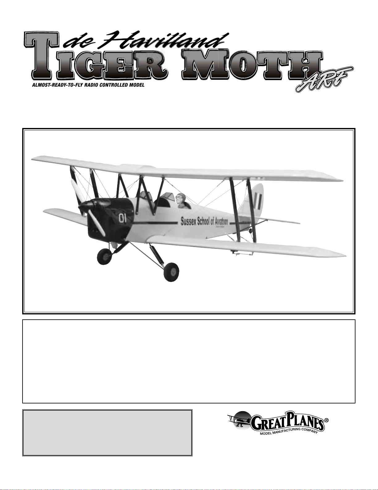
Thank you for purchasing the Great Planes Tiger Moth ARF.
This model is a re-creation of the deHavilland D.H. 82 Tiger
Moth which was originally developed from the D.H. Gipsy
Moth. It was first flown in October of 1931 and became the
basic trainer for Britain's Royal Air Force. More than 8,700
Tiger Moths were manufactured, with 4,200 going to the
Royal Air Force, where it trained thousands of pilots for
World War II service.It continued to serve the post-war RAF
until 1951.There are more than 250 still flying today.
The Tiger Moth has a wingspan of 29 ft.4 in., a fuse length
of 23 ft. 11 in., and is powered by a 145-hp deHavilland
Gipsy Major 1C inline piston engine. The plane has a
maximum speed of 107 mph, a ceiling of 14,600 ft. and a
range of 275 miles.
We hope your new Great Planes Tiger Moth ARF provides
you with many hours of flying fun and enjoyment.
For the latest technical updates or manual corrections for
the Tiger Moth, visit the web site listed below and select the
Great Planes Tiger Moth ARF.A “tech notice” box will appear
in the upper left corner of the page if there is new technical
information or changes.
http://www.greatplanes.com/airplanes/index.html
1. Your Great Planes Tiger Moth ARF should not be
considered a toy, but rather a sophisticated, working model
that functions very much like a full-size airplane.Because of
its performance capabilities, the Tiger Moth, if not
assembled and operated correctly, could possibly cause
injury to yourself or spectators and damage property.
2. You must assemble the model according to the
instructions. Do not alter or modify the model, as doing so
may result in an unsafe or unflyable model. In a few cases
the instructions may differ slightly from the photos.In those
instances the written instructions should be considered
as correct.
3. You must take time to assemble straight, true and strong.
4. You must use an R/C radio system that is in first-class
condition, and a correctly sized engine and components
(fuel tank, wheels, etc.) throughout the assembly process.
PRO TECT YOUR MODEL,YOURSELF
& OTHERS...FOLLOW THESE
IMPORTANT SAFETY PRECAUTIONS
INTRODUCTIONTABLE OF CONTENTS
2
Page 3
5.You must properly install all R/C and other components so
that the model operates properly on the ground and in the air.
6. You must check the operation of the model before every
flight to insure that all equipment is operating and that the
model has remained structurally sound. Be sure to check
clevises or other connectors often and replace them if they
show any signs of wear or fatigue.
7. If you are not already an experienced R/C pilot, you
should fly the model only with the help of a competent,
experienced R/C pilot.
Remember:Take y our time and follow the instructions to
end up with a well-built model that is straight and true.
If you have not flown this type of model before, we
recommend that you get the assistance of an experienced
pilot in your R/C club for your first flights. If you're not a
member of a club, your local hobby shop has information
about clubs in your area whose membership includes
experienced pilots.
In addition to joining an R/C club, we strongly recommend y ou
join the AMA (Academy of Model Aeronautics). AMA
membership is required to fly at AMA sanctioned clubs.There
are over 2,500 AMA chartered clubs across the country.
Among other benefits, the AMA provides insurance to its
members who fly at sanctioned sites and events .Additionally,
training programs and instructors are available at AMA club
sites to help you get started the right way. Contact the AMA at
the address or toll-free phone number below:
Academy of Model Aeronautics
5151 East Memorial Drive
Muncie, IN 47302-9252
Tele. (800) 435-9262
Fax (765) 741-0057
Or via the Internet at:
http://www.modelaircraft.org
The Tiger Moth qualifies as a "giant scale" model and is an
excellent sport-scale model. It is therefore eligible to fly in
IMAA events. The IMAA (International Miniature Aircraft
Association) is an organization that promotes noncompetitive flying of giant-scale models.If you plan to attend
an IMAA event, contact the IMAA for a copy of the IMAA
Safety Code at the address or telephone number below.
IMAA
205 S. Hilldale Road
Salina, KS 67401
(866) 366-4622
Or via the Internet at: http://www.fly-imaa.org
This is a partial list of items required to finish the Tiger Moth
that may require planning or decision making before starting
to build. Order numbers are provided in parentheses.
The Tiger Moth requires a minimum 4 channel radio system
such as the Futaba®4VF (FUTJ62**). It requires 5 S-3003
servos (FUTM0031), two Pro HD 12" Aileron Extensions
(HCAM2711), and one Pro HD Y-Harness (HCAM2751).
The following engines are recommended for the Tiger Moth:
OS®.61 FX two-stroke (OSMG0561)
SuperTigre®G-61 ABC w/muffler two-stroke (SUPG0181)
SuperTigre G-75 Ring w/muffler two-stroke (SUPG0205)
OS FS-91 II Surpass™four-stroke (OSMG0896)
OS FS-91 II Surpass w/pump four-stroke (OSMG0890)
Remember that this is a scale model that is intended to fly at
scale-like speeds, so throttle management should be practiced.
This is the list of hardware and accessories required to finish
the Great Planes Tiger Moth. Order numbers are provided
in parentheses.
❏Propellers – Follow engine manuf acturer’ s recommendations
❏ R/C foam rubber (1/4" - HCAQ1000, or 1/2" - HCAQ1050)
❏ 30-Minute Epoxy (GPMR6047)
❏ 3' Medium fuel tubing (GPMQ4131)
Hardware and Accessories
ADDITIONAL ITEMS REQUIRED
Engine Recommendations
Radio Equipment
DECISIONS YOU MUST MAKE
We, as the kit manufacturer, provide you with a top quality
kit and instructions, but ultimately the quality and flyability
of your finished model depends on how you assemble it;
therefore, we cannot in any way guarantee the
performance of your completed model, and no
representations are expressed or implied as to the
performance or safety of your completed model.
3
Page 4
❏ Top Flite
®
MonoKote®sealing iron (TOPR2100)
❏ Top Flite MonoKote trim seal iron (TOPR2200)
❏ Top Flite MonoKote heat gun (TOPR2000)
❏ Top Flite Hot Sock
™
iron cover (TOPR2175)
In addition to common household tools and hobby tools, this
is the "short list" of the most important items required to
build the Tiger Moth. Great Planes Pro™CA and Epoxy glue
are recommended.
❏ 1/2 oz.Thin Pro CA (GPMR6001)
❏ 1/2 oz. Medium Pro CA+ (GPMR6007)
❏ Hobby knife (HCAR0105)
❏ #11 blades (HCAR0211)
❏ Small T-pins (HCAR5100)
❏ Builder's triangle (HCAR0480)
❏ Electric drill and 1/16" [1.6mm], 3/32" [2.4mm], 3/16"
[4.8mm], 17/64" [6.7mm], and 5/16" [7.9mm] drill bits
❏ 8-32 Tap Set (GPMR8108)
❏ Small Phillips (HCAR1024) and flat blade (HCAR1002)
screwdrivers
❏ Pliers with wire cutter (HCAR0630)
Here is a list of optional tools mentioned in the manual that
will help you build the Tiger Moth.
❏ Great Planes CG Machine
™
(GPMR2400)
❏ Easy-Touch
™
Bar Sander (GPMR6170)
❏ Easy Fueler
™
fuel filling valve for glow fuel (GPMQ4160)
❏ Hobbico
®
Servo Horn Drill (HCAR0698)
❏ 1/4-scale pilot (optional, WBRQ4131)
❏ Switch and Charge Jack Mounting Set (GPMM1000)
❏ Top Flite Precision Magnetic Prop Balancer
™
(TOPQ5700)
❏ Great Planes Fingertip Prop Balancer (GPMQ5000)
❏ Black Top Flite MonoKote Trim Sheet (TOPQ4109)
❏ Black Top Flite LustreKote
®
Paint (TOPR7208)
❏ Straightedge with scale (HCAR0475)
❏ Cutting mat (HCAR0456)
❏ Masking Tape (TOPR8018)
❏ CA Debonder (GPMR6039)
❏ CA Applicator tips (GPMR6033)
❏ CA accelerator (GPMR6034)
❏ 6-Minute Epoxy (GPMR6045)
❏ R/C-56 Canopy Glue (JOZR5007)
❏ Epoxy Brushes (GPMR8060)
❏ Mixing Sticks (GPMR8055)
❏ Threadlocker (GPMR6060)
❏ Denatured Alcohol (for epoxy clean up)
❏ 1/16" to 1/4" drill bit set
❏ Curved Tip Canopy Scissors for Trimming Plastic Parts
(HCAR0667)
❏ Dead Center
™
Engine Mount Hole Locator (GPMR8130)
❏ Great Planes Receiver Guard (GPMM1010)
❏ Great Planes AccuThrow
™
Deflection Gauge (for measuring
control throws, GPMR2405)
MonoKote colors used on this model.
The Tiger Moth is cov ered in Top Flite MonoKote film.Should
additional covering for patchwork or repairs be required, use
Top Flite Cub Yellow MonoKote (TOPQ0220).
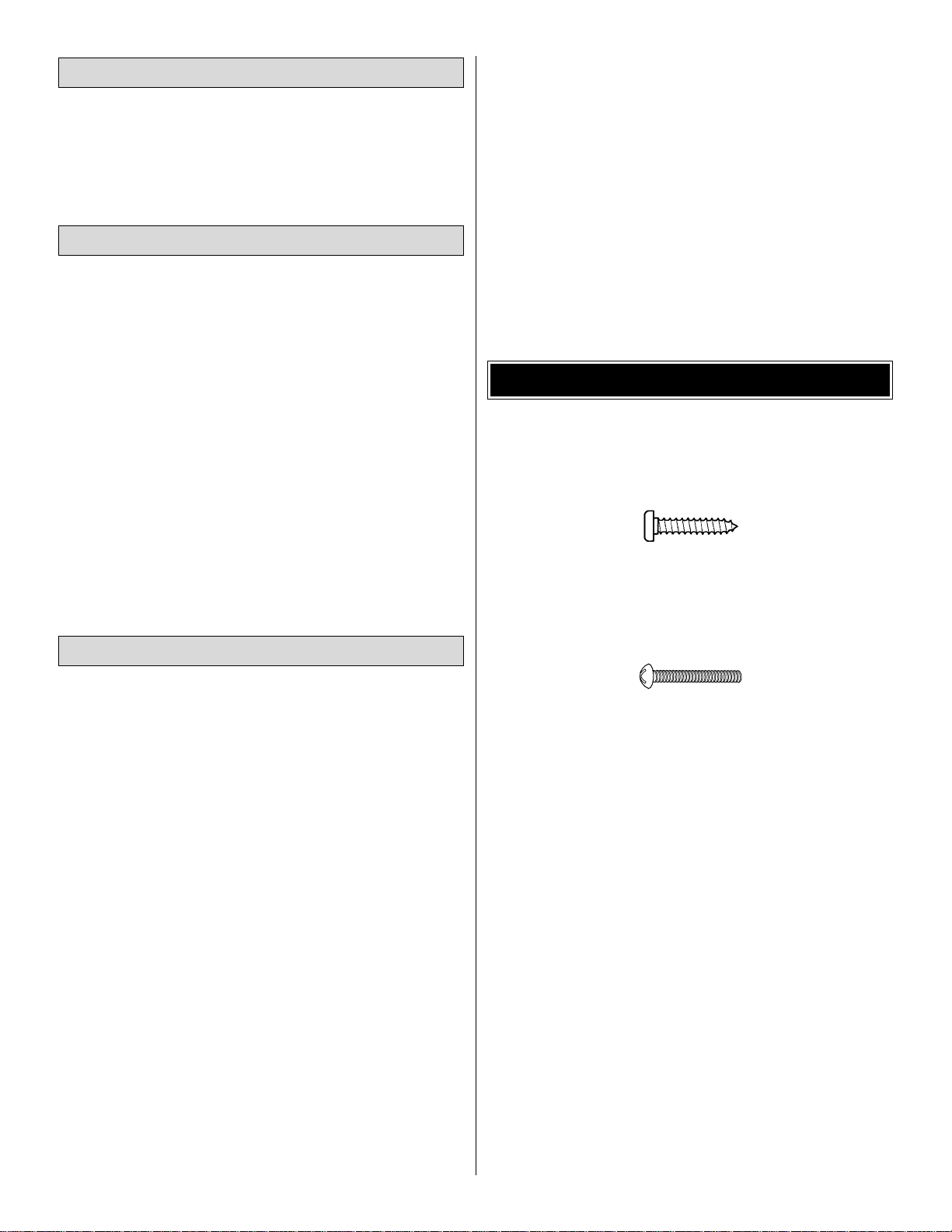
• There are two types of screws used in this kit:
Sheet metal screws are designated by a number and a
length. For example #6 x 3/4"
This is a number six screw that is 3/4" long.
Machine screws are designated by a number, threads per
inch, and a length. For example 4-40 x 3/4"
This is a number four screw that is 3/4" long with
forty threads per inch.
• When you see the term
test fit
in the instructions, it
means that you should first position the part on the
assembly without using any glue, then slightly modify or
custom fit the part as necessar y for the best fit.
• Whenever the term
glue
is written you should rely upon
your experience to decide what type of glue to use.When a
specific type of adhesive works best for that step, the
instructions will make a recommendation.
• Whenever just
epoxy
is specified you may use
either
30-minute (or 45-minute) epoxy or6-minute epoxy. When
30-minute epoxy is specified it is highly recommended that
you use only 30-minute (or 45-minute) epoxy, because you
will need the working time and/or the additional strength.
• Photos and sketches are placed before the step they
refer to. Frequently you can study photos in following steps
to get another view of the same parts.
IMPORTANT BUILDING NOTES
Optional Supplies and Tools
Adhesives and Building Supplies
Covering Accessories
4
Page 5
5
To order replacement par ts for the Great Planes Tiger Moth ARF, use the order numbers in the Replacement Parts List
that follows. Replacement par ts are available only as listed. Not all parts are available separately (an aileron cannot be
purchased separately, but is only available with the wing kit).Replacement par ts are not available from Product Support,
but can be purchased from hobby shops or mail order/Internet order firms. Hardware items (screws, nuts, bolts) are also
available from these outlets. If you need assistance locating a dealer to purchase par ts, visit www.greatplanes.com and
click on "Where to Buy." If this kit is missing par ts, contact Great Planes Product Support.
Replacement Parts List
Order Number Description How to Purchase
Missing pieces ......................Contact Product Support
Instruction manual.................Contact Product Suppor t
Full-size plans.......................Not available
GPMA2229......................................Upper Wing Kit
GPMA2230......................................Lower Wing Kit
GPMA2231......................................Fuselage Kit
GPMA2232......................................Tail Set
GPMA2233......................................Cowl
GPMA2234......................................Landing Gear
ORDERING REPLACEMENT PARTS
.........
Contact Your Hobby
Supplier to Purchase
These Items
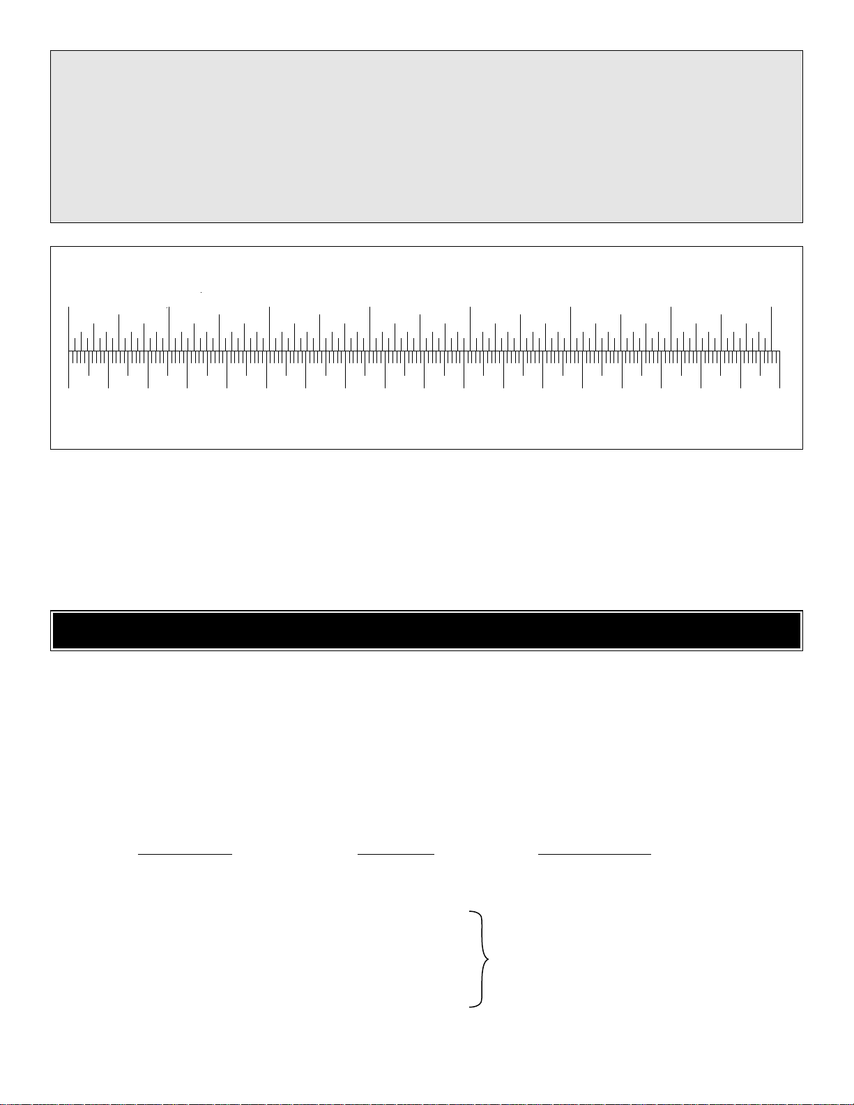
To convert inches to millimeters, multiply inches by 25.4
1/64" = .4mm
1/32" = .8mm
1/16" = 1.6mm
3/32" = 2.4mm
1/8" = 3.2mm
5/32" = 4mm
3/16" = 4.8mm
1/4" = 6.4mm
3/8" = 9.5mm
1/2" = 12.7mm
5/8" = 15.9mm
3/4" = 19mm
1" = 25.4mm
2" = 50.8mm
3" = 76.2mm
6" = 152.4mm
12" = 304.8mm
15" = 381mm
18" = 457.2mm
21" = 533.4mm
24" = 609.6mm
30" = 762mm
36" = 914.4mm
Metric Conversions
Inch Scale
0" 1" 2" 3" 4" 5" 6" 7"
0 10 20 30 40 50 60 70 80 90 100 110 120 130 140 150 160 170 180
Metric Scale
Page 6
6
(4)8-32 x 1" SHCS (attaching engine mount)
(4) 8-32 Blind nuts (attaching engine mount)
(6) 6-32 x 1/8" Set screws (3/16" wheel collars)
(4) 3/16" Wheel collars (main wheels)
(1) 3/32" Wheel collar (tail wheel)
(1) Brass screw lock connector (throttle linkage)
(1) Nylon retainer (throttle linkage)
(1) 4-40 x 1/4” SHCS (throttle linkage)
(2) 1/4" - 20 Nylon bolts (attach wing to fuse)
(6) Nylon clevises (ailerons, elevators, rudder)
(4) Faslinks (ailerons, elevator, rudder servos)
(4) Nylon landing gear straps
(5) Nylon control horns (ailerons, elevs, rudder)
(26) Silicone clevis retainers
(1) 2" x 9" CA hinge strip (all control surfaces)
(3) .074" x 36" Thread one end pushrod
(rudder, elev)
(2) .074" x 12" Thread one end pushrod (aileron)
(1) .074" x 17.5" Thread one end pushrod (throttle)
(1) 11-3/4” Pushrod Guide Tube (throttle)
(8) #8 Washers (engine mount)
(3) 36”Pushrod Guide Tube (pre-installed in fuse)
(12) 4-40 Nylon lock nut (struts & cabanes)
(12) #4 Washers (struts & cabanes)
(12) 4-40 x 3/4" SHCS (struts & cabanes)
(12) #2 x 1/2" Phillips head screws (LG straps
and aileron control horns)
(4) 8-32 x 3/4" SHCS (engine to mount)
(2) 5/32" Wheel collars (elevator pushrods)
(1) 4-40 x 1/8" Set screw (3/32" wheel collar)
(4) 2-56 x 5/8" Machine screw (elev cntl horns)
(20) 2-56 Metal clevises (flying wires)
(2) 2-56 x 3/4" SHC Screw (rud cntl horn)
(1) 2-1/4" Black Spinner
(2) 1/4" - 20 Blind nuts (pre-installed in wing
hold down plate)
(4) 4 x 18mm Wood screws (cabanes to fuse)
(18) 3 x 12mm Wood screws (brackets for
struts and wires)
(4) 2.5 x 8mm Wood screws (cowl to fuse)
(24) Aluminum crimp tubes (flying wires)
(12) 2-56 Threaded brass ends (flying wires)
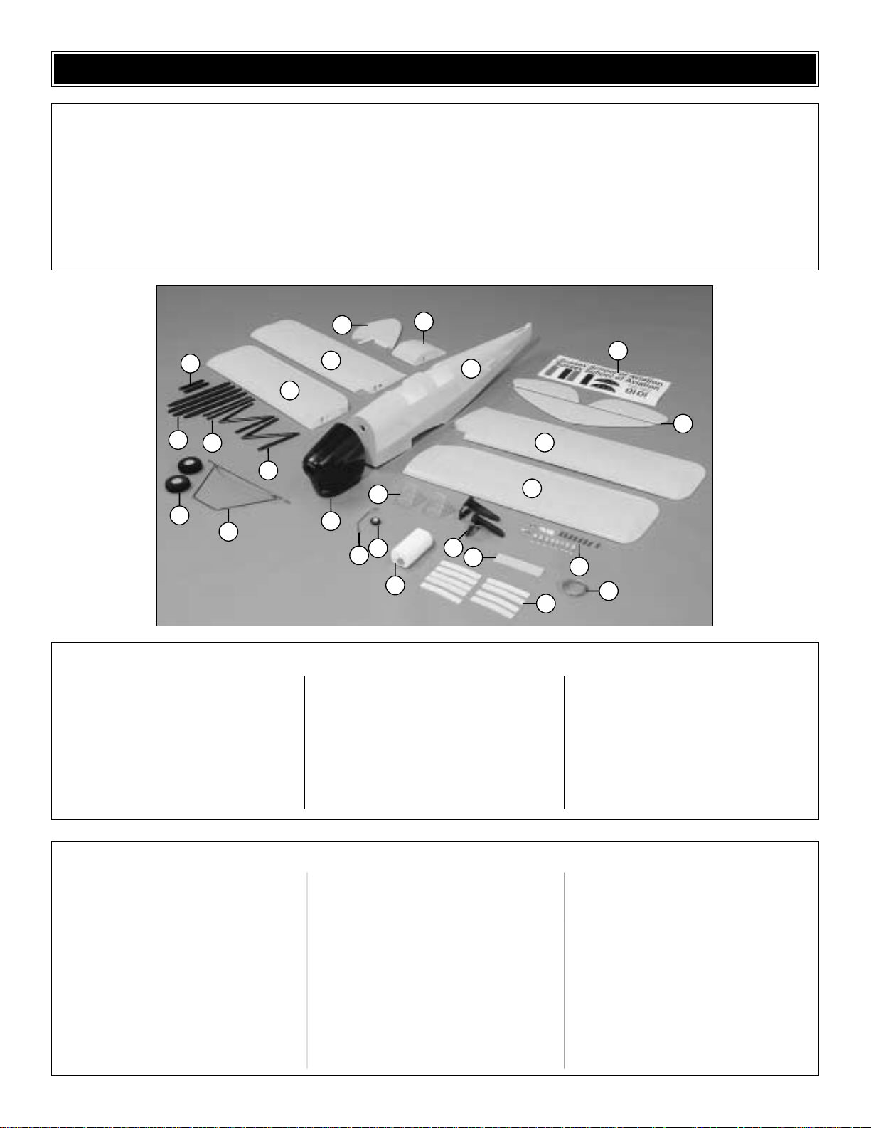
Kit Contents (Not Photographed)
1. Top Wing
2. Top Wing Center Section
3. Bottom Wing w/Ailerons
4. Fuselage
5. Stabilizer w/ Elevators
6. Fin w/ Rudder
7. Painted Fiberglass Cowl
8. Landing Gear
9. 3-1/4" Wheels (2)
10. Cabane Struts (2)
11. Interplane Struts (4)
12. Stab Braces (2)
13. Landing Gear Covers (2)
14. Wing Joiners (9)
15. Tail Wheel Wire & Bearing
16. 1-1/4" Tail Wheel
17. Wind Screens (2)
18. Fuel Tank w/ Hardware
19. Engine Mount (R & L Halves)
20. Wing Bolt Mounting Plate
21. Flying Wire
22. Metal Brackets (24)
23. Decal Sheet
Kit Contents (Photographed)
Before starting to build, use the Kit Contents list to take an inventory of your kit to make sure it is complete, and inspect
the parts to make sure they are of acceptable quality. If any parts are missing or are not of acceptable quality, or if you
need assistance with assembly, contact Great Planes Product Support. When reporting defective or missing parts, use
the part names exactly as they are written in the Kit Contents list on this page.
Great Planes Product Support:
Phone: (217) 398-8970
Fax: (217) 398-7721
E-mail: airsupport@greatplanes.com
KIT CONTENTS
13
11
12
9
8
10
6
2
3
1
17
7
16
15
18
19
4
20
23
5
3
1
22
21
14
Page 7
❏ 1. If you have not done so already, remove the major
parts of the kit from the box (wings, fuse, cowl, tail parts,
etc.) and inspect them for damage. If any parts are damaged
or missing, contact Product Support at the address or
telephone number listed on page 6.
❏ 2. Remove the masking tape and separate the ailerons
from the wing, the rudder from the fin and the elevators
from the stab. Tighten the covering with a covering iron on
high heat with a covering sock. Apply pressure over sheeted
areas to thoroughly bond the covering to the wood.
❏❏1. Drill a 3/32" [2.4mm] hole, 1/2" [13mm] deep in the
center of each hinge slot to allow the CA to “wick” in. Follow-up
with a #11 blade to clean-out the slots. Hint: If you have one,
use a high-speed rotary tool to drill the holes.
❏❏2. Use a sharp #11 blade to cut a strip of covering
from the aileron hinge slots in both halves of the Bottom
Wing and ailerons.
❏ 3. Cut fourteen 3/4" x 1" [19mm x 25mm] hinges from the
CA hinge strip. Snip off the corners as shown so they go in
easier. Insert three of the hinges into the aileron hinge slots.
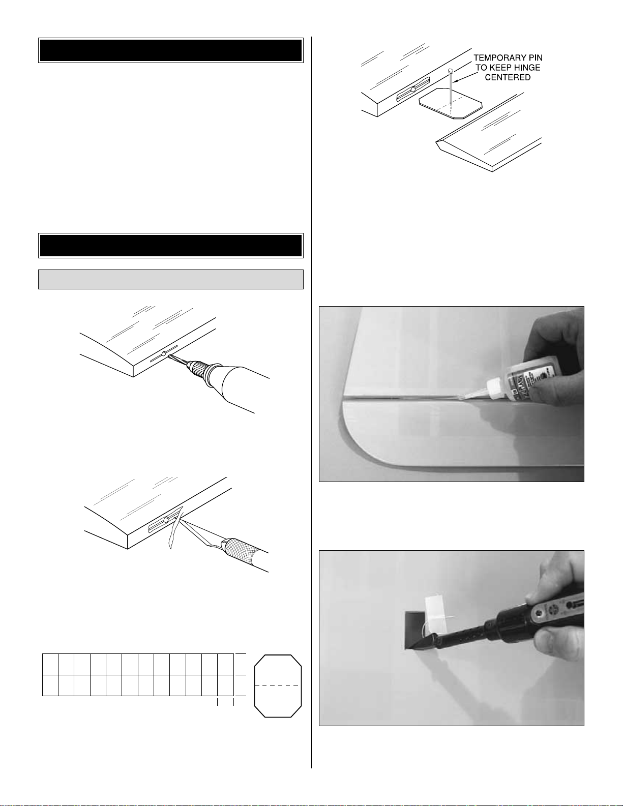
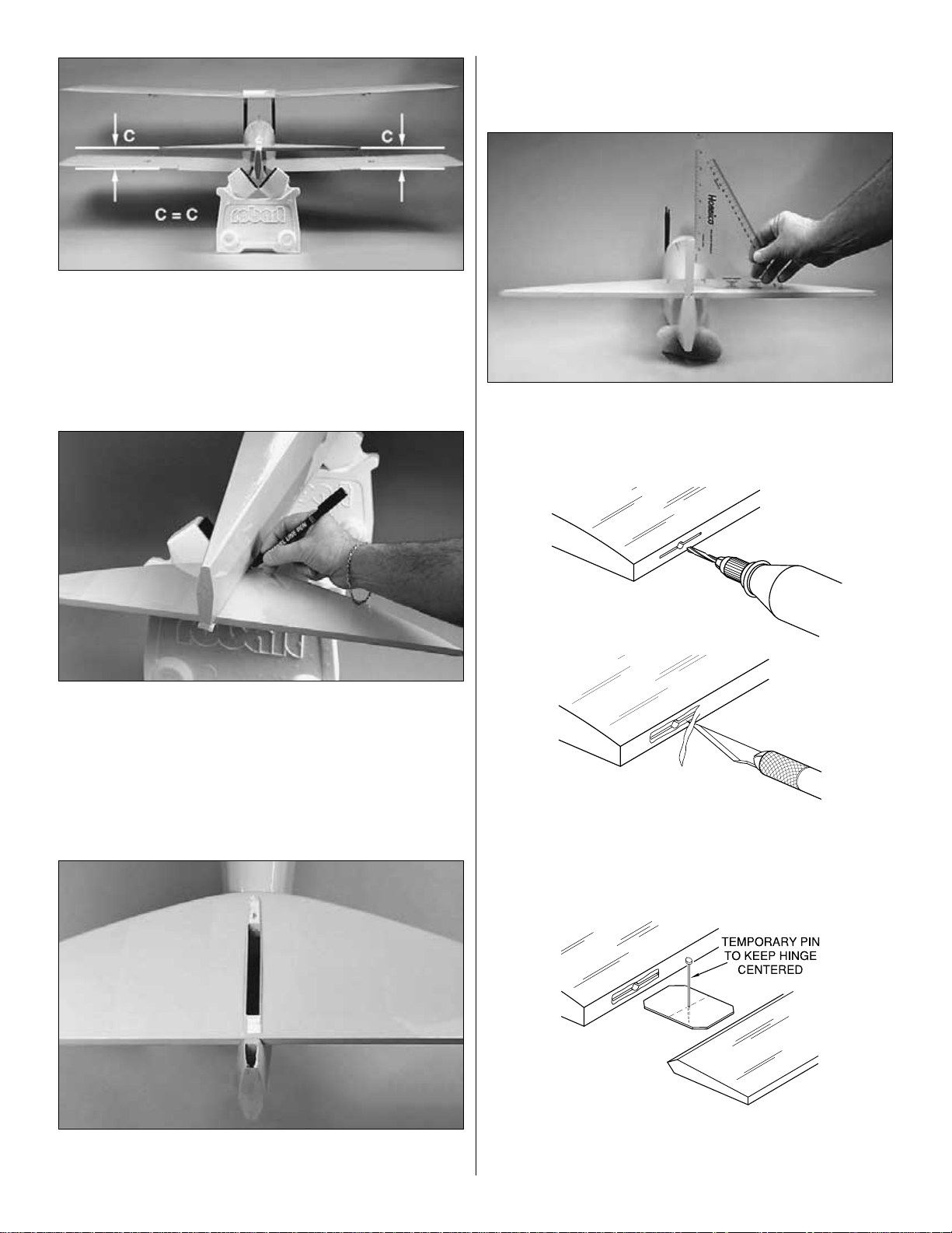
❏❏4. Test fit the ailerons to the wing with the hinges. If
the hinges don't remain centered, stick a pin through the
middle of the hinge to hold it in position.
❏❏5. Remove any pins you may have inserted into the
hinges. Adjust the aileron so there is a small gap between the
LE of the aileron and the wing. The gap should be just small
enough to see light through or to slip a piece of paper through.
❏❏6. Apply six drops of thin CA to the top and bottom of
each hinge. Do not use CA accelerator. After the CA has
fully hardened, test the hinges by pulling on the aileron.
❏❏7. Cut the covering 1/8" [3mm] inside the opening in
the wing for the aileron servo. Use a trim iron to seal the
covering to the edges of the opening.
1"
1"
3/4"
AWAY FROM THE SLOT
CUT THE COVERING
DRILL A 3/32" HOLE
1/2" DEEP, IN CENTER
OF HINGE SLOT
Hook Up the Ailerons
ASSEMBLE THE WING
PREPARATIONS
7
Page 8
❏❏8. Cut the covering away from the hole in the top of
the wing and feed the string, which is taped to the root rib
through the hole in top of the wing and re-tape it securely
near the hole.
❏❏9. Install the servo per the manufacturer’s instructions.
Connect a 12" [305mm] servo extension wire (HCAM2711)
to the servo and secure it with tape or heat shrink material.
Tie the string to the aileron servo wire and pull the servo
wire out of the hole on top of the wing with the string. Tape
the connector to the wing to prevent it from falling back
inside the wing. Then discard the string.
❏❏10. Place the servo into the wing and drill 1/16" [1.6mm]
holes in the wing for the servo mounting screws. Then,
mount the aileron servo using the screws that came with it.
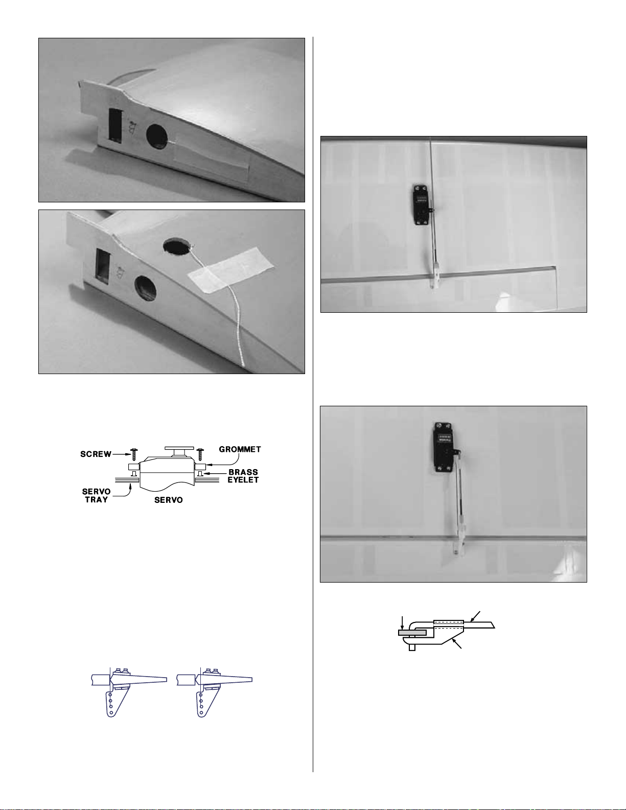
❏❏11. The servo arms for the aileron servos are placed
so that they point outboard from the servo.This is necessary
for proper function. Draw a line to the servo arm hole at
90-degrees from the aft edge of the aileron bay. At this
location mark and drill the two 1/16" [1.6mm] holes into the
bottom of the aileron for mounting the nylon control horn.
Saturate the holes with thin CA, wipe away any residual CA
and allow it to fully harden. Mount the aileron control horn
to the aileron with two #2 x 1/2" [13mm] sheet metal screws.
❏❏12. Enlarge the hole in the servo arm with a Hobbico
Servo Horn Drill (HCAR0698) or a #48 or 5/64" [2mm] drill bit.
Install a clevis retainer and a clevis onto a 12" [305mm]
pushrod approximately 25 turns. Center the servo arm, align
the aileron with the trailing edge of the wing, and then mark the
location of the servo arm hole on the pushrod with a felt tip pen.
❏❏13. Measure 1/2” [13mm] past the marked location
toward the non-threaded end of the pushrod and cut it off at
that point. Make a 90-degree bend in the pushrod at the
marked location (servo arm hole). Connect the servo to the
aileron as shown using a Faslink Connector.
❏ 14. Repeating steps 1 - 12, assemble the other wing the
same way.
FasLink
2-56 (.074") Pushrod Wire
Servo Horn
Correct Incorrect
8
Page 9
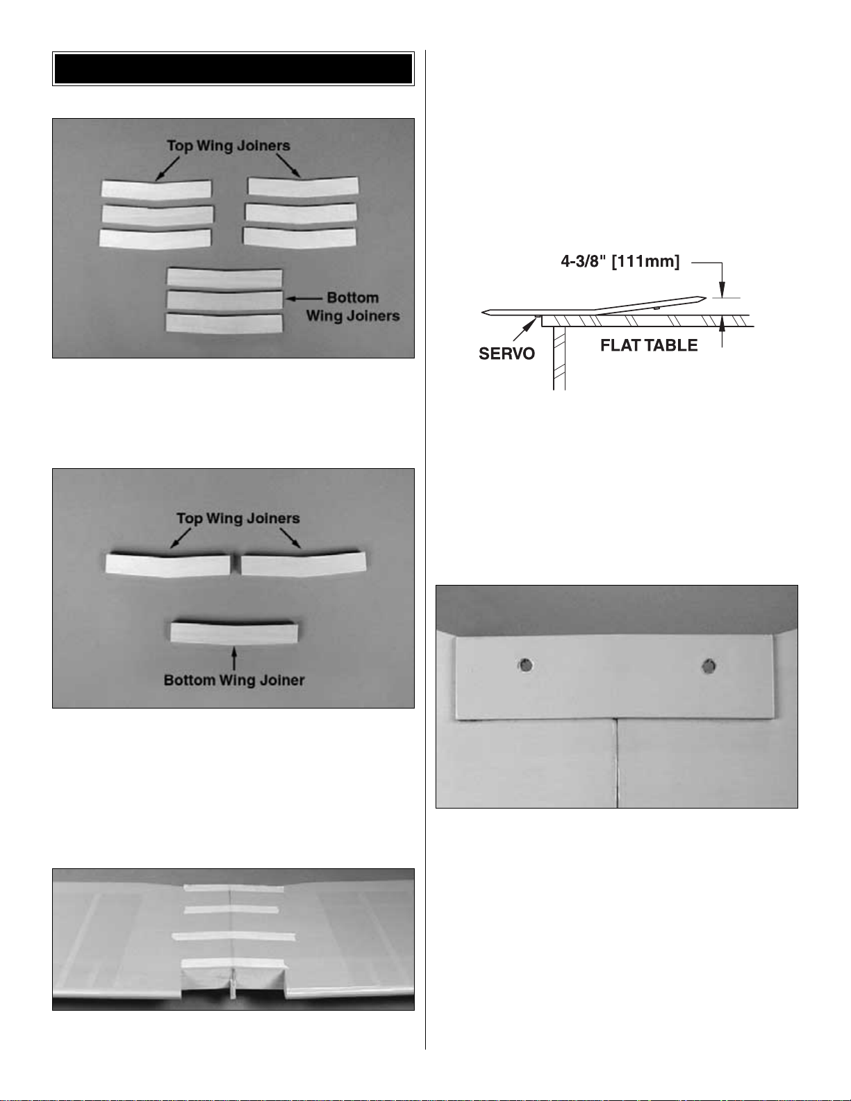
❏ 1. Locate the nine die-cut ply wing joiners. Note that
there will be three matching wing joiners which make up the
bottom wing joiner. Mark these “bottom wing joiner.” There
will also be six matching wing joiners which make up the two
joiners for the top wing. Mark these “top wing joiner.”
❏ 2. Use 6-minute epoxy to glue the joiners together to form
three plywood joiners as shown.
❏ 3. After the epoxy has cured, sand off any excess glue
and test fit the lower wing joiner into the two wing halves,
making sure the lower wing halves fit together properly and
form a good fitting joint.
❏ 4. Using 30-minute epoxy, thoroughly coat the root rib of
both lower wing halves and the wing joiner. Be sure to apply a
generous amount of epoxy into the inside of the wing joiner
pocket. Important: Make sure the joiner is fitted upright to
ensure the proper dihedral. Then, join the wing halves tightly,
holding them together. Use a paper towel to wipe away excess
epoxy that comes out of the wing.Tightly hold the wing together
with masking tape, making certain both halves are in full
contact and that the leading and trailing edges align.
(Proceed to the next step immediately!)
The following sketch shows how the lower wing dihedral
is measured.
❏ 5. Check for the correct dihedral angle while joining the
wing. Place one wing panel on a flat surface and measure
the distance from the elevated wing tip to the table top. This
distance should be 4-3/8" [111mm] measured at the wing tip
former, located 4" [102mm] back from the leading edge.
Note: You will need to avoid the servo to get an
accurate measurement.
You can use a paper towel dampened with rubbing alcohol
for any epoxy clean-up. Do not disturb the wing until the
epoxy has fully hardened.
❏ 6. Outline the 1/8" [3mm] plywood wing bolt plate on the
bottom of the lower wing and cut the MonoKote covering
away using a Hobbico Hot Knife (HCAR0770). You may
also use a hobby knife with a #11 blade. If using this
method be sure not to cut into the wood under the covering
as this will weaken the structure.
❏ 7. After removing the covering use 6-minute epoxy to
glue the wing bolt plate to the wing and allow the epoxy to
cure completely.
❏ 8. Drill two 17/64" [6.7mm] holes through the wing bolt
plate from the top of the wing using the pre-drilled holes in
the wing as a guide.
JOIN THE WINGS
9
Page 10

❏ 9. Install four 90-degree metal brackets into the
pre-drilled holes in the bottom of the top wing center section
with 3mm x 12mm wood screws.
❏ 10. Locate the pre-drilled holes in the bottom of the top
wing panels. Mount the four compound-bend metal
brackets (two in each wing panel) using 3mm x 12mm wood
screws. The interplane struts and flying wires will attach to
them in a later step.
❏ 11. Locate the pre-drilled holes in the top of the bottom
wing and install the four compound-bend metal brackets in
place. Install two 45-degree metal brackets in the pre-drilled
holes near the center of the wing with 3mm x 12mm wood
screws as shown in the photo.
❏ 12. Attach the bottom wing to the fuselage, using two
1/4”-20 nylon wing bolts.
❏ 13. Mount the cabane struts to the fuselage using the
following procedure: Locate the four pre-drilled holes in the
fuselage for mounting the Cabane Struts and saturate the
holes with thin CA to harden the wood. After the CA cures,
mount the Cabane Struts as shown in the photo, using four
4mm x 8mm wood screws (supplied).
10
Page 11

❏ 14. Attach the top wing center section by inserting two
4-40 x 3/4" [19mm] socket head cap screws with #4 washers
through the 45-degree metal bracket, the rear cabane struts
and the 90-degree brackets. Then install the 4-40 nylon lock
nuts onto the socket head cap screws. Mount the forward
cabane struts to the forward 90-degree brackets by inserting
two 4-40 x 3/4" [19mm] socket head cap screws with #4
washers through the cabane struts and the 90-degree
brackets. Install the 4-40 nylon lock nuts on these screws.
Note: In order to set the proper dihedral for the top wing, it
will be joined on the model as follows.
❏ 15. Test fit the wing joiners into the center section of the
top wing. Slide the two wing panels onto the wing joiners,
and temporarily hold them in place with a few pieces of tape.
(Do not glue yet).
❏ 16. Attach the four interplane struts to the top and bottom
wings using 4-40 x 3/4" [19mm] socket head cap screws with #4
washers through the struts and compound-bend metal brackets.
Note that the longer struts are to be mounted in the aft position,
and the shorter struts in the forward position. Temporarily install
the 4-40 nylon lock nuts to hold things in place.
❏ 17. Inspect the fit of the top wing to the center section.
They should line up along the bottom edge, and there
should be little or no gap where the wing panels join the
center section. If any misfits are observed, you may loosen
the screws holding the center section to the cabane struts,
make minor adjustments, and re-tighten the screws.
❏❏18.Use 30-minute epoxy to thoroughly coat the root rib
of the right wing half, the outside rib of the center section,
and the wing joiner. Apply a generous amount of epoxy into
the wing joiner slots in the wing panel and the center
section. Insert the wing joiner (upright), and slide the wing
panel into place. Working quickly, reattach the interplane
struts and make certain the root rib is in full contact with the
center section and that they align perfectly along the bottom
edge. Hold the wing panel securely to the center section
with strips of masking tape. Wipe away excess epoxy with a
paper towel dampened with alcohol. Do not disturb the wing
until the epoxy has fully hardened.
❏ 19. Repeat the above step to attach the top left wing panel.
NOTE:
The flying wires included with the Tiger Moth are
not functional or required for structural integrity.
❏❏1. Use the photos above as a reference guide in
assembling the flying wires. Using the coil of the flying wire,
six 2-56 clevises, six 2-56 threaded brass ends, six 2-56
nuts, eight aluminum crimp tubes and six silicone clevis
retainers, make the flying wires for the right wings first. Start by
assembling two clevises with the threaded brass ends and
nuts. Note that the single ends of the wire sets are located next
to the fuse. Cut four lengths of wire from the coil 17” [432mm]
long and attach four of them to two of the threaded brass ends
using four aluminum crimp tubes as shown in the photo.
Install Flying Wires
11
Page 12

❏❏2. Attach one of your assembled double wire sets to
the bracket located on the aft upright of the cabane and the
other to the bracket installed into the bottom wing. Assemble
four more clevises, four threaded brass ends, four nuts and
four silicone clevis retainers and place them on the brackets
you installed with the interplane struts. Run the wires from
the single end assembly to the proper clevis, slip the
aluminum crimp tube over the wire and run the wire through
the hole drilled in the threaded brass end. Pull the wire tight,
slip the wire back through the crimp tube twice and use a
pair of pliers to squeeze the crimp tube holding the wire in
place. Cut off any excess wire protruding from the crimp
tube. Repeat this process to the remaining three clevises on
the interplane struts.
❏❏3. The flat metal straps which are placed at the top and
bottom of each interplane strut are the locations for the “X”
wires which run between the two interplane struts as shown
in the photo. Cut two pieces of wire 11" [279mm] and make
two wire assemblies, using the same process as above.
These wires run from the bottom of the aft interplane strut to
the top of the forward and from the bottom of the forward strut
to the top of the aft strut, forming an X-brace between the
forward and aft struts as shown in the previous photo.
❏ 4. Repeat this process for the left wings.
❏ 1. Locate the horizontal stab. Trial fit the stab onto the
stab saddle. Measure the distance from the center of the fuse
to each tip of the stab. This distance needs to be the same.
Make adjustments as needed until the distance is equal.
❏ 2. Place a T-pin into the center of the fuse at the firewall.
Measure from the pin to the tip of the stab. The distance
from the pin to the stab tips needs to be equal on both sides.
Once satisfied with the position of the stab securely tape the
stab into place. A Hobbico Retractable Fabric Tape
Measure (HCAR0478) works well for this step.
Mount the Stab and Fin
ASSEMBLE THE FUSELAGE
12
A
A
A=A
Page 13
❏ 3. With the wings in place and the stab firmly taped, place
the model in a building stand such as a Robart Super
Stand II, (ROBP1402). Stand ten to fifteen feet behind the
model and view the stab and wing. If the stab and wing align
with each other, proceed to the next step. If the stab and
wing do not align, sand the “high side” of the slot in the fuse
where the stab fits until the stab aligns with the wing.
❏ 4. Turn the model over and mark the location of the fuse
sides on the stab. Cut and remove the MonoKote covering
from the stab with a hot knife using the same technique as
on the bottom wing.
❏ 5. Using epoxy, glue the stab into place, and carefully re-
check the alignment of the stab. Allow the epoxy to
thoroughly cure before moving the model.
❏ 6. After the epoxy has cured, remove the MonoKote
covering from the section where the fin fits into the
horizontal stab and just forward and aft of the opening, being
careful not to cut into the wood. This will allow the fin to fit
properly into place.
❏ 7. Trial fit the fin to the fuse. Use a triangle like the
Hobbico Builders Triangle (HCAR0480) to make sure the
fin is square. When satisfied with the fit and alignment, glue
the fin into place using epoxy.
❏ 8. Drill a 3/32" [2.4mm] hole, 1/2" [13mm] deep in the
center of each hinge slot to allow the CA to “wick” in. Followup with a #11 blade to clean-out the slots and cut a strip of
covering from the hinge slots in the stab and elevators.
❏ 9. Install the hinges into the stab and then test fit the
elevators. If the hinges don't remain centered, stick a pin
through the middle of the hinge to hold it in position.
AWAY FROM THE SLOT
CUT THE COVERING
DRILL A 3/32" HOLE
1/2" DEEP, IN CENTER
OF HINGE SLOT
13
Page 14

❏ 10. Remove any pins you may have inserted into the
hinges. Adjust the elevator so there is a small gap between the
LE of the elevator and the stab. The gap should be small-just
enough to see light through or to slip a piece of paper through.
❏ 11. Apply six drops of thin CA to the top and bottom of
each hinge. Do not use CA accelerator. After the CA has
fully hardened, test the hinges by pulling on the elevators.
❏ 12. To attach the rudder drill a 3/32" [2.4mm] hole, 1/2"
[13mm] deep in the center of each hinge slot to allow the CA
to “wick” in. Follow-up with a #11 blade to clean-out the slots
and cut a strip of covering from the hinge slots in the fin and
rudder. Trial fit two hinges into the rudder and place onto the
fin. Locate the tail wheel wire in the rudder with the two
hinges in place and mark the location (approximately 1-1/2"
or 38mm from the top of the angle on the bottom of the
rudder). Also mark the location of the nylon bearing and cut
a slot for it in the aft end of the fuse with a #11 blade.
❏ 13. Drill a 3/32" (2.4mm) hole in the rudder at the marked
location to the depth of the tail wheel wire and cut a groove for
the wire from the bottom of the rudder with a sharp hobby knife
or a Groove Tube (GPMR8140) to accommodate the wire.
❏ 14. Apply petroleum jelly to the tail wheel bearing where
the wire passes through. This will prevent the wire from
being glued to the bearing. Permanently join the rudder to
the fin using epoxy to glue the “arm” portion of the tail gear
wire into the rudder and the bearing into the aft of the fuse.
Use thin CA to glue in the hinges after the epoxy has cured.
❏ 15. Locate the two stab support braces and drill a 1/8"
[3mm] hole in the tab portion at both ends of each brace.
Mark the location as shown in the photo and drill a 1/16"
[1.6mm] hole in the bottom of the stab and fuse. Apply thin
CA to each of the holes to harden the area. Install the braces
with the four 3mm x 12mm Phillips head wood screws.
14
Page 15
❏ 1. Note: The proper thrust angle for the engine has been
built-in. Find the location markings on the firewall and use a
straight edge to draw lines between the horizontal and
vertical marks. Center the Great Planes engine mount
using the tick marks on the mount to match the lines on the
firewall.When satisfied with the location use a small punch or
sharpened wire on one end to mark the four engine mount
bolt holes to the firewall by making dimples in the wood.
❏ 2. Drill four 7/32" [5.6mm] holes through the firewall at the
marks. Apply epoxy to the four 8-32 blind nuts, being careful
not to get the glue into the threads, and place them into the
holes on the back of the firewall. Attach the engine mount to
the firewall with four 8-32 x 1" socket head cap screws and
#8 flat washers. This will draw the blind nuts into the back of
the firewall. Allow the epoxy to cure.
❏ 3. Place the back plate of the spinner on the engine.
Adjust the width of the mount to fit the engine. Center the
molded-in “tick” marks on the engine mount over the lines on
the firewall. Tighten the mounting bolts.
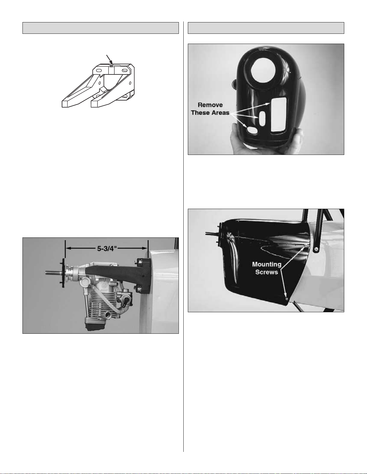
❏ 4. Temporarily secure the engine to the mount with the
back plate of the spinner 5-3/4" [146mm] from the firewall.
A Great Planes Dead Center Engine Mount Hole Locator
(GPMR8130) works well to mark the location for the engine
mount holes onto the engine mount.
❏ 5. Remove the engine from the mount. Drill four #29
[9/64" or 3.6mm] holes through the mount at the marks you
made. Tap 8-32 threads into the mount. Attach the engine to
the mount with four 8-32 x 3/4" socket head cap screws and
#8 flat washers.
❏ 1. Locate the cowl and as shown in the photo, remove
the formed portions of the cowl designed for engine cooling
with a sharp hobby knife or Dremel tool.
❏ 2. With the engine mounted on the fuselage, place the
cowling on the fuselage and attach the spinner back plate.
❏ 3. Position the cowl on the fuse so it is in alignment with the
spinner. Be certain there is at least a 3/32" [2.4mm] gap
between the front of the cowl and the back plate of the spinner.
❏ 4. Drill a 3/32" [2.4mm] hole through the cowl and
mounting blocks in the positions shown. Apply thin CA to the
holes to reinforce the area. Enlarge the hole in the cowl
only with a 1/8" [3mm] drill bit. Mount the cowl to the
fuselage with four 2.5 x 8mm wood screws.
Mount the Cowl
Install the Engine
15
Tick marks for alignment
Page 16

❏ 5. Install the muffler on your engine. Cut holes in the cowl
where necessary for items such as the engine exhaust,
needle valve, glow plug igniter, or fuel filler valve. For this
particular application the use of an O.S. Exhaust Header
Pipe (OSMG2625) allows the positioning of the muffler in a
perfect location under the model as shown in the photo above.
❏ 1. Assemble the stopper and tubes as shown in the
photo, then insert them into the tank. Tighten the screw to
expand the stopper, thus sealing the tank. Be certain the
fuel line weight (clunk) at the end of the fuel line inside the
tank does not contact the rear of the tank. Otherwise, the
line may become stuck above the fuel level and stop the fuel
flow. Remember (or use a felt-tip pen to mark) which tube is
the fuel pick-up tube and which tube is the vent.
❏ 2. Install the tank into the fuse. Fit the neck through the hole
in the firewall. Be certain the vent tube inside the tank is pointing
upward. Glue the tank into place with epoxy or silicone.
❏ 3. In order to mount the optional Great Planes Easy-
Fueler for glow fuel (GPMQ4160) used on this model,
make a mount from 1/8" [3mm] plywood (not included with
this kit) or use the filler valve mount from a Great Planes
Handy Mounts set (GPMQ6000). Use epoxy to securely
glue the filler valve mount to the firewall in a location where
the filler valve will be accessible outside the cowl when it is
time to fuel the engine.
❏ 4. You will notice that the firewall has been fuel proofed
but it is necessary to use epoxy or fuelproof paint to coat the
fuel filler mount. Make the necessary hole in the cowl to
access the filler valve.
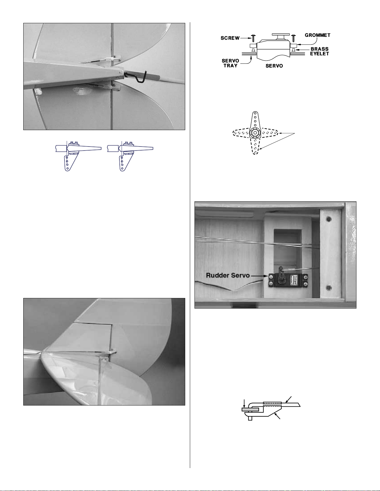
❏ 1. Make the elevator pushrods by threading two nylon
clevises approximately 25 full turns onto the end of two
36" [914mm] pushrods. Connect each clevis to a large
nylon control horn. Be sure to use the silicone clevis
retainer as shown.
Install the Radio
FINAL ASSEMBLY
Install the Fuel Tank
16
Page 17
❏ 2. Slide the pushrods into the guide tubes at the aft end
of the fuse. Slightly bend the pushrods as necessary so the
clevises will fit on the control horns. Carefully locate the
control horn with the hinge line as shown in the sketch. Drill
3/32" (2.4mm) holes through the elevators and then harden
the area with thin CA. Mount the horns with 2-56 X 5/8"
screws and the nylon mounting plates on the other side of
the control horn.
❏ 3. Make the rudder pushrod by threading a nylon clevis
approximately 25 full turns onto the end of a 36" [914mm]
pushrod. Connect the clevis to a large nylon control horn. Be
sure to use the silicone clevis retainer as shown.
❏ 4. Slide the pushrod into the guide tube at the aft end of the
fuse. Bend the pushrod as necessary so the control horn will fit
on the rudder and clear the horizontal stabilizer. Position the
control horn in a location that will not interfere with the elevator
movement. Drill 3/32" [2.4mm] holes through the rudder and
harden the area with CA. Mount the horn with 2-56 x 3/4"
[19mm] socket head cap screws and the nylon mounting plate
on the other side of the control horn.
❏ 5. Install the rubber grommets and brass eyelets in the
servos using the above sketch as a guide.
❏ 6. Cut off three arms from three servo horns included with
your radio control set to make them into “one arm” servo
horns. Use an Easy-Touch Bar Sander (GPMR6170) to
remove the remaining jagged edges left from the cut-off arms.
❏ 7. Install the rudder servo by marking its location and drill
1/16" [1.5mm] pilot holes through each mark. Harden the
areas with thin CA. Mount the servo with the screws
provided with your radio system.
❏ 8. Center the rudder servo and mark the pushrod where
it crosses the servo arm. Enlarge the servo horn hole with a
5/64" [2mm] drill bit.
❏ 9. Make a 90-degree bend in the pushrod on your mark
and cut the pushrod off 1/2" [13mm] beyond the bend. Insert
the wire through the enlarged hole in the servo arm. Secure
the wire in place with a nylon FasLink pushrod keeper.
FasLink
2-56 (.074") Pushrod Wire
Servo Horn
Cut Off
Unused
Arms
Correct Incorrect
17
Page 18

❏ 10. Install the elevator servo using the same method as with
rudder servo above. Since the Tiger Moth uses two pushrods to
control the elevators, we will begin by attaching one pushrod
from one elevator (just as we did in step nine for the rudder) and
then we will join the second pushrod with the first. Center the
elevators and the elevator servo and mark the first pushrod
where it crosses the servo arm with a felt tip pen. Enlarge the
servo horn hole with a 5/64" [2mm] drill bit.
❏ 11. Slide two of the 5/32" [4mm] wheel collars onto the
pushrod wire. Make a 90-degree bend in the pushrod on your
mark and cut the pushrod off ½" [13mm] beyond the bend.Insert
the wire through the enlarged hole in the servo arm. Secure the
wire in place with a nylon FasLink pushrod keeper.
❏ 12. While keeping both elevators centered, connect the
two elevator pushrods to each other with two 5/32" [4mm]
wheel collars as shown in the photo. Use Thread lock
(GPMR6165) on the screws to prevent loosening.
❏ 13. Install the throttle servo between the rudder and
elevator servos by marking its location and drill 1/16"
[1.5mm] pilot holes through each mark. Then harden those
areas with thin CA. Mount the servo with the screws
provided with your radio system.
❏ 14. You may find it easier to install your receiver, battery
pack and switch harness before installing the throttle linkage.
❏ 15. Installation of the receiver can be done using a Great
Planes Receiver Guard (GPMM1010) or wrap the battery
pack and receiver in at least 1/4" of R/C foam rubber
(HCAQ1000) and mount them on balsa rails which can then
be glued into the fuselage. On our model with an OS FS-91
II Surpass w/Pump (OSMG0890), the battery was mounted
under the fuel tank as far forward as possible and the
receiver as shown in the photo to minimize the amount of
weight required to balance the model at the correct C.G.
❏ 16. Mount the receiver on/off switch in the forward
cockpit. A Great Planes Switch & Charge Jack Mounting
Set (GPMM1000), not included, was used on this model. A
Du-Bro Remote Safety Igniter (DUBP1200) was also used
on the model and is shown in the photo. You may want to
paint the cockpit interiors prior to installing these items.
❏ 17. Extend the receiver antenna and guide it out of the
fuselage and connect it to the tail wheel gear. Be certain
there is a strain relief on the antenna to keep stress off the
solder joint inside the receiver. On our model we drilled a
3/32" [2.4mm] hole through the bottom of the fuselage aft of
the bottom wing and routed the antenna through the hole.
The antenna was connected to a hook made from a cut-off
servo arm connected to a rubber band placed around the
tail wheel gear.
18
Page 19

❏ 18. Drill a 3/16" hole through the firewall for the throttle
pushrod guide tube. Be certain to not drill into the tank! It
may be helpful to remove the engine for this step, so it does
not interfere with drilling the hole (or use an extended drill bit).
❏ 19. Lightly sand then insert the 3/16" x 11-3/4"
[4.8mm x 298mm] throttle pushrod guide tube through the
hole in the firewall. Bend the 17-1/2" [445mm] throttle
pushrod if necessary. Attach a nylon clevis approximately 25
turns and add a silicone retainer. Then connect it to the
carburetor arm on the engine. Connect the opposite end of
the pushrod wire to the throttle servo with a screw-lock
pushrod connector.
❏ 20. Make a brace for the aft end of the guide tube from
1/8" [3mm] scrap balsa or plywood (not included) and glue it
in place as shown. Also make another brace to fit across the
former as shown in the photo.You will have to slip the outer
tube through the braces or make them with a slot in order fit
them properly. Glue the tube into place with epoxy at both
braces and at the firewall.
❏ 21. Set the carburetor to the closed position. Turn the
radio system on and move the throttle servo to the fully
closed position. Tighten the socket head cap screw in the
screw-lock pushrod connector. Cut off the excess pushrod
aft of the screw-lock pushrod connector.
❏ 22. Make certain all the servo arms are secured to the
servos with the screws that came with them and that all the
clevises have retainers.
❏ 23. Install your aileron extension wire, supplied with your
radio system into the receiver. Connect the Y-connector
(HCAM2751) to the aileron servo wires taped to the top of
the bottom wing. Be sure to tape or use heat shrink material
to secure these connections.
❏ 1. Place the landing gear in the grooved hardwood
mounts at the bottom of the fuselage and mark the position
for the nylon landing gear straps as shown. Drill 1/16"
[1.6mm] holes in the locations for the straps and harden the
areas with thin CA. Secure the straps with #2 x 1/2" Phillips
head screws.
Install the Landing Gear
19
RETAINER
Page 20

❏ 2. Locate the landing gear fairings and trial fit around
the landing gear wire as shown in the photo. When satisfied
with the fit, glue them into place with 6-minute epoxy, joining
the halves as you do. Clamp in place until the epoxy is
thoroughly cured.
❏ 3. File a flat spot on the gear wires and attach the main
wheels with the four 3/16" [4.8mm] wheel collars supplied
with the model. Also attach the tail wheel with the 3/32"
[2.4mm] wheel collar. Use thread-lock on the set screws to
prevent them from coming loose in flight.
❏ 1. Apply the decals as shown in the photo. The easiest
and most accurate way to position the decals is to first cut
them from the sheet. When ready to apply one of the decals,
even though these are the sticky back type, submerge it in a
tub of warm water mixed with liquid dish soap (about a
tablespoon of soap per gallon of water) and peel the decal
from the backing. Lay the decal on the model and position it
exactly where you want it. Use a paper towel to wipe away
most of the water, then use a soft balsa sheet or something
similar to squeegee the rest of the water from under the
decal. Allow to dry overnight before flying the model.
❏ 2. On our model we placed a black trim stripe cut from
a black Top Flite MonoKote Trim Sheet (TOPQ4109).
❏ 3. As instructed before you will note that we painted the
two cockpits flat black. We also placed a 1/4-scale Williams
Brothers Scale Pilot (WBRQ2625) inside the rear cockpit
for added realism.
❏ 4. Apply the decals for the instrument panel as shown
in the photo. Locate the two molded windscreens. Carefully
cut the excess plastic away. Mask and paint the frames of
the windscreens with Formula-U or Cheveron black paint.
When the paint is completely dry glue them into position
using R/C-56 Canopy Glue (JOZR5007).
❏ 1. Turn on the transmitter and receiver and center the
trim tabs. If necessary, remove the servo arms from the
servos and reposition them so they are centered. Reinstall
the screws that hold on the servo arms.
❏ 2. With the transmitter and receiver still on, check all the
control surfaces to see if they are centered.If necessary, adjust
the clevises on the pushrods to center the control surfaces.
Check the Control Directions
GET THE MODEL READY TO FLY
Finishing Touches
20
Page 21

❏ 3. Make certain that the control surfaces and the
carburetor respond in the correct direction as shown in the
diagram. If any of the controls respond in the wrong direction,
use the servo reversing in the transmitter to reverse the
servos connected to those controls. Be certain the control
surfaces have remained centered. Adjust if necessary.
Use a Great Planes AccuThrow Deflection Gauge
(GPMR2405) or a ruler to accurately measure and set the
control throw of each control surface as indicated in the
chart that follows. If your radio does not have dual rates, we
recommend setting the throws at the low rate setting.
NOTE: The throws are measured at the widest part of the
elevators, rudder and ailerons.
At this stage the model should be in ready-to-fly condition
with all of the systems in place including the engine, landing
gear, covering and paint and the radio system.
❏ 1. Use a felt-tip pen or 1/8” [3mm]-wide tape to accurately
mark the C.G. on the top of the bottom wing next to both
sides of the fuselage. Start from the forward-most point of
the leading edge (not the cut-out area), and measure back
2-3/4” [70mm]. See the sketch on page 22.
This is where your model should balance for your first
flights. Later, you may wish to experiment by shifting the
C.G. up to 2-1/2" [64mm] back from the leading edge or 3"
[76mm] back from the leading edge to change the flying
characteristics. Moving the C.G. forward may improve the
smoothness and stability, but it may then require more
speed for takeoff and make it more difficult to slow for
landing. Moving the C.G. aft makes the model more
maneuverable, but could also cause it to become too
difficult for you to control. In any case, start at the location
we recommend and do not at any time balance your
model outside the recommended range.
More than any other factor, the C.G. (balance point) can
have the greatest effect on how a model flies and may
determine whether or not your first flight will be
successful. If you value this model and wish to enjoy it for
many flights, DO NOT OVERLOOK THIS IMPORTANT
PROCEDURE. A model that is not properly balanced will
be unstable and possibly unflyable.
Balance the Model (C.G.)
IMPORTANT: The Tiger Moth has been extensively flown
and tested to arrive at the throws at which it flies best.
Flying your model at these throws will provide you with the
greatest chance for successful first flights. If, after you
have become accustomed to the way the Tiger Moth flies,
you would like to change the throws to suit your taste, that
is fine. However, too much control throw could make the
model difficult to control, so remember, “more is not
always better.”
These are the recommend control surface throws:
High Rate Low Rate
ELEVATOR: 1" [25.4mm] up 3/4" [19.1mm] up
1" [25.4mm] down 3/4" [19.1mm] down
RUDDER: 2" [50.8mm] right 2" [50.8mm] right
2" [50.8mm] left 2" [50.8mm] left
AILERONS: 3/4" [19.1mm] up 1/2" [12.7mm] up
3/4" [19.1mm] down 1/2" [12.7mm] down
Set the Control Throws
CARBURETOR WIDE OPEN
RUDDER MOVES RIGHT
LEFT AILERON MOVES DOWN
RIGHT AILERON MOVES UP
ELEVATOR MOVES UP
4-CHANNEL
TRANSMITTER
(STANDARD MODE 2)
4-CHANNEL RADIO SETUP
TRANSMITTER
4-CHANNEL
TRANSMITTER
4-CHANNEL
TRANSMITTER
4-CHANNEL
21
Page 22

❏ 2. With the wings attached to the fuselage, all parts of the
model installed (ready to fly) and an empty fuel tank, place
the model upside-down on a Great Planes CG Machine
(GPMR2400), or lift it upside-down at the balance point
you marked.
❏ 3. If the tail drops, the model is “tail heavy” and the battery
pack and/or receiver must be shifted forward or weight must be
added to the nose to balance. If the nose drops, the model is
“nose heavy” and the battery pack and/or receiver must be
shifted aft or weight must be added to the tail to balance. If
possible, relocate the battery pack and receiver to minimize or
eliminate any additional ballast required. If additional weight is
required, nose weight may be easily added by using a
“spinner weight” (GPMQ4645 for the 1 oz. weight, or
GPMQ4646 for the 2 oz. weight). If spinner weight is not
practical or is not enough, use Great Planes “stick-on” lead
weights (GPMQ4485). A good place to add stick-on nose
weight is to the firewall (don't attach weight to the cowl-it is not
intended to support weight). Begin by placing incrementally
increasing amounts of weight on the bottom of the fuse over the
firewall until the model balances. Once you have determined
the amount of weight required, it can be permanently attached.
If required, tail weight may be added by cutting open the bottom
of the fuse and gluing it permanently inside.
Note: Do not rely upon the adhesive on the back of the lead
weight to permanently hold it in place. Over time, fuel and
exhaust residue may soften the adhesive and cause the
weight to fall off. Use #2 sheet metal screws, RTV silicone or
epoxy to permanently hold the weight in place.
❏ 4. IMPORTANT: If you found it necessary to add any
weight, recheck the C.G. after the weight has been installed.
❏ 1. With the wing level, have an assistant help you lift the
model by the engine propeller shaft and the bottom of the
fuse under the TE of the fin. Do this several times.
❏ 2. If one wing always drops when you lift the model, it means
that side is heavy. Balance the airplane by adding weight to the
other wing tip. An airplane that has been laterally balanced
will track better in loops and other maneuvers.
No matter if you fly at an AMA sanctioned R/C club site or if you
fly somewhere on your own, you should always have your
name, address, telephone number and AMA number on or
inside your model. It is required at all AMA R/C club flying sites
and AMA sanctioned flying events. Fill out the identification tag
on page 25 and place it on or inside your model.
Follow the battery charging instructions that came with your
radio control system to charge the batteries. You should
always charge your transmitter and receiver batteries the
night before you go flying and at other times as
recommended by the radio manufacturer.
NOTE: Checking the condition of your receiver battery pack
is highly recommended. All battery packs, whether it's a
trusty pack you've just taken out of another model, or a new
battery pack you just purchased, should be cycled, noting
the discharge capacity. Oftentimes, a weak battery pack can
be identified (and a valuable model saved!) by comparing its
actual capacity to its rated capacity. Refer to the instructions
and recommendations that come with your cycler. If you
don't own a battery cycler, perhaps you can have a friend
cycle your pack and note the capacity for you.
Carefully balance your propeller and spare propellers before
you fly. An unbalanced prop can be the single most significant
cause of vibration that can damage your model. Not only will
engine mounting screws and bolts loosen, possibly with
disastrous effect, but vibration may also damage your radio
receiver and battery. Vibration can also cause your fuel to
foam, which will, in turn, cause your engine to run hot or quit.
We use a Top Flite Precision Magnetic Prop Balancer
™
(TOPQ5700) in the workshop and keep a Great Planes
Fingertip Prop Balancer (GPMQ5000) in our flight box.
Balance the Propellers
Charge the Batteries
Identify Your Model
PREFLIGHT
Balance the Model Laterally
2-3/4" [70mm]
22
Page 23

If the engine is new, follow the engine manufacturer's
instructions to break-in the engine. After break-in,
confirm that the engine idles reliably, transitions smoothly
and rapidly to full power and maintains full powerindefinitely. After you run the engine on the model, inspect
the model closely to make sure all screws remained tight,
the hinges are secure, the prop is secure and all pushrods
and connectors are secure.
Ground check the operational range of your radio before the
first flight of the day. With the transmitter antenna collapsed
and the receiver and transmitter on, you should be able to
walk at least 100 feet away from the model and still have
control. Have an assistant stand by your model and, while
you work the controls, tell you what the control surfaces are
doing. Repeat this test with the engine running at various
speeds with an assistant holding the model, using hand
signals to show you what is happening. If the control
surfaces do not respond correctly, do not fly! Find and
correct the problem first. Look for loose servo connections or
broken wires, corroded wires on old servo connectors, poor
solder joints in your battery pack or a defective cell, or a
damaged receiver crystal from a previous crash.
Keep all engine fuel in a safe place, away from high heat,
sparks or flames, as fuel is very flammable. Do not smoke
near the engine or fuel; and remember that engine exhaust
gives off a great deal of deadly carbon monoxide. Therefore
do not run the engine in a closed room or garage.
Get help from an experienced pilot when learning to
operate engines.
Use safety glasses when starting or running engines.
Do not run the engine in an area of loose gravel or sand; the
propeller may throw such material in your face or eyes.
Keep your face and body as well as all spectators away from the
plane of rotation of the propeller as you start and run the engine.
Keep these items away from the prop: loose clothing, shirt
sleeves, ties, scarfs, long hair or loose objects such as
pencils or screwdrivers that may fall out of shirt or jacket
pockets into the prop.
Use a “chicken stick” or electric starter to start the engine.
Do not use your fingers to flip the propeller. Make certain the
glow plug clip or connector is secure so that it will not pop
off or otherwise get into the running propeller.
Make all engine adjustments from behind the rotating propeller.
The engine gets hot! Do not touch it during or right after
operation. Make sure fuel lines are in good condition so fuel
will not leak onto a hot engine, causing a fire.
To stop a glow engine, cut off the fuel supply by closing off
the fuel line or following the engine manufacturer's
recommendations. Do not use hands, fingers or any other
body part to try to stop the engine. To stop a gasoline
powered engine an on/off switch should be connected to the
engine coil. Do not throw anything into the propeller of a
running engine.
Read and abide by the following Academy of Model
Aeronautics Official Safety Code:
1. I will not fly my model aircraft in sanctioned events, air shows,
or model flying demonstrations until it has been proven to be
airworthy by having been previously successfully flight tested.
2. I will not fly my model aircraft higher than approximately
400 feet within 3 miles of an airport without notifying the
airport operator. I will give right of way to and avoid flying in
the proximity of full scale aircraft. Where necessary an
observer shall be used to supervise flying to avoid having
models fly in the proximity of full scale aircraft.
3. Where established, I will abide by the safety rules for the
flying site I use and I will not willfully and deliberately fly my
models in a careless, reckless and/or dangerous manner.
7. I will not fly my model unless it is identified with my name
and address or AMA number, on or in the model.
9. I will not operate models with pyrotechnics (any device
that explodes, burns, or propels a projectile of any kind).
1. I will have completed a successful radio equipment ground
check before the first flight of a new or repaired model.
2. I will not fly my model aircraft in the presence of
spectators until I become a qualified flier, unless assisted by
an experienced helper.
Radio Control
General
AMA SAFETY CODE (
EXCERPT
)
Failure to follow these safety precautions may result
in severe injury to yourself and others.
ENGINE SAFETY PRECAUTIONS
Range Check
Ground Check
23
Page 24

3. I will perform my initial turn after takeoff away from the pit
or spectator areas and I will not thereafter fly over pit or
spectator areas, unless beyond my control.
4. I will operate my model using only radio control
frequencies currently allowed by the Federal
Communications Commission...
During the last few moments of preparation your mind may
be elsewhere anticipating the excitement of the first flight.
Because of this, you may be more likely to overlook certain
checks and procedures that should be performed before the
model is flown. To help avoid this, a checklist is provided to
make sure these important areas are not overlooked. Many
are covered in the instruction manual, so where appropriate,
refer to the manual for complete instructions. Be sure to
check the items as off they are completed (that's why it's
called a
check list
!).
❏ 1. Fuelproof all areas exposed to fuel or exhaust residue
such as the cowl mounting blocks, wing saddle area, etc.
❏ 2. Check the C.G. according to the measurements
provided in the manual.
❏ 3. Be certain the battery and receiver are securely
mounted in the fuse. Simply stuffing them into place
with foam rubber is not sufficient.
❏ 4. Extend your receiver antenna and make sure it has a
strain relief inside the fuselage to keep tension off the
solder joint inside the receiver.
❏ 5. Balance your model laterally as explained in
the instructions.
❏ 6. Use thread locking compound to secure critical
fasteners such as the set screws that hold the wheel
axles to the struts, screws that hold the carburetor arm
(if applicable), screw-lock pushrod connectors, etc.
❏ 7. Add a drop of oil to the axles so the wheels will turn freely.
❏ 8. Make sure all hinges are securely glued in place.
❏ 9. Reinforce holes for wood screws with thin CA where
appropriate (servo mounting screws, cowl mounting
screws, etc.).
❏ 10. Confirm that all controls operate in the correct direction
and the throws are set up according to the manual.
❏ 11. Make sure there are silicone retainers on all the
clevises and that all servo arms are secured to the
servos with the screws included with your radio.
❏ 12. Secure connections between servo wires and Y-
connectors or servo extensions and the connection
between your battery pack and the on/off switch with
vinyl tape, heat shrink tubing or special clips suitable
for that purpose.
❏ 13. Make sure any servo extension cords you may have
used do not interfere with other systems (servo arms,
pushrods, etc.).
❏ 14. Secure the pressure tap (if used) to the muffler with
high temp RTV silicone, thread locking compound or
J.B. Weld.
❏ 15. Make sure the fuel lines are connected and are not
kinked.
❏ 16. Use an incidence meter to check the wings for twists
and attempt to correct before flying.
❏ 17. Balance your propeller (and spare propellers).
❏ 18. Tighten the propeller nut and spinner.
❏ 19. Place your name, address, AMA number and
telephone number on or inside your model.
❏ 20. Cycle your receiver battery pack (if necessary) and
make sure it is fully charged.
❏ 21. If you wish to photograph your model, do so before
your first flight.
❏ 22. Range check your radio when you get to the flying
field. Perform the range check with the engine
running and without the engine running.
The Tiger Moth is a great-flying model that flies
smoothly and predictably. The Tiger Moth does not,
however, possess the self-recovery characteristics of a
primary R/C trainer and should be flown only by
experienced R/C pilots.
A fully cowled engine may run at a higher temperature than
an un-cowled engine. For this reason, the fuel mixture
should be richened so the engine runs at about 200 rpm
below peak speed. By running the engine slightly rich, you
will help prevent dead-stick landings caused by overheating.
CAUTION: If, while flying, you notice any unusual sounds,
such as a low-pitched “buzz,” this may indicate control
surface
flutter
. Because flutter can quickly destroy
components of your airplane, any time you detect flutter
you must immediately cut the throttle and land the
airplane! Check all servo grommets for deterioration (this
may indicate which surface fluttered) and make sure all
pushrod linkages are secure and free of play. If the control
surface fluttered once, it probably will flutter again under
similar circumstances unless you can eliminate the freeplay or flexing in the linkages. Here are some things which
can cause flutter: Excessive hinge gap; Not mounting
control horns solidly; Poor fit of clevis pin in horn; Sideplay of pushrod in guide tube caused by tight bends; Poor
fit of Z-bend in servo arm; Insufficient glue used when
gluing in the elevator joiner wire; Excessive
play
or
backlash
in servo gears; and Insecure servo mounting.
Fuel Mixture Adjustments
FLYING
CHECK LIST
24
Page 25

Before you get ready to takeoff, see how the model handles
on the ground by doing a few practice runs at low speeds
on the runway. Hold “up” elevator to keep the tail wheel on
the ground. If necessary, adjust the tail wheel so the model
will roll straight down the runway. If you need to calm your
nerves before the maiden flight, shut the engine down and
bring the model back into the pits. Top off the fuel, then
check all fasteners and control linkages for peace of mind.
Remember to takeoff into the wind. When you're ready, point
the model straight down the runway, hold a bit of up elevator
to keep the tail on the ground to maintain tail wheel steering,
then gradually advance the throttle. As the model gains
speed decrease up elevator allowing the tail to come off the
ground. One of the most important things to remember with
a tail dragger is to always be ready to apply right rudder to
counteract engine torque. Gain as much speed as your
runway and flying site will practically allow before gently
applying up elevator, lifting the model into the air. At this
moment it is likely that you will need to apply more right
rudder to counteract engine torque. Be smooth on the
elevator stick, allowing the model to establish a gentle climb
to a safe altitude before turning into the traffic pattern.
For reassurance and to keep an eye on other traffic, it is a
good idea to have an assistant on the flight line with you.Tell
him to remind you to throttle back once the plane gets to a
comfortable altitude. While full throttle is usually desirable for
takeoff, most models fly more smoothly at reduced speeds.
Take it easy with the Tiger Moth for the first few flights,
gradually getting acquainted with it as you gain confidence.
Adjust the trims to maintain straight and level flight. After
flying around for a while and while still at a safe altitude with
plenty of fuel, practice slow flight and execute practice
landing approaches by reducing the throttle to see how the
model handles at slower speeds. Add power to see how she
climbs as well. Continue to fly around, executing various
maneuvers and making mental notes (or having your
assistant write them down) of what trim or C.G. changes
may be required to fine tune the model so it flies the way you
like. Mind your fuel level, but use this first flight to become
familiar with your model before landing.
To initiate a landing approach, lower the throttle while on the
downwind leg. Allow the nose of the model to pitch
downward to gradually bleed off altitude. Continue to lose
altitude, but maintain airspeed by keeping the nose down as
you turn onto the crosswind leg. Make your final turn toward
the runway (into the wind) keeping the nose down to
maintain airspeed and control. Level the attitude when the
model reaches the runway threshold, modulating the throttle
as necessary to maintain your glide path and airspeed. If
you are going to overshoot, smoothly advance the throttle
(always ready on the right rudder to counteract torque) and
climb out to make another attempt. When you're ready to
make your landing flare and the model is a foot or so off the
deck, smoothly increase up elevator until it gently touches
down. Once the model is on the runway and has lost flying
speed, hold up elevator to place the tail on the ground,
regaining tail wheel control.
One final note about flying your model. Have a goal or flight
plan in mind for every flight. This can be learning a new
maneuver(s), improving a maneuver(s) you already know, or
learning how the model behaves in certain conditions (such
as on high or low rates). This is not necessarily to improve
your skills (though it is never a bad idea!), but more
importantly so you do not surprise yourself by impulsively
attempting a maneuver and suddenly finding that you've run
out of time, altitude or airspeed. Every maneuver should be
deliberate, not impulsive. For example, if you're going to do
a loop, check your altitude, mind the wind direction
(anticipating rudder corrections that will be required to
maintain heading), remember to throttle back at the top and
make certain you are on the desired rates (high/low rates).
A flight plan greatly reduces the chances of crashing your
model just because of poor planning and impulsive moves.
Remember to think.
Have a ball! But always stay in control
and fly in a safe manner.
GOOD LUCK AND GREAT FLYING!
Landing
Flight
Takeoff
2525
Page 26

26
The fierce Luftwaffe Stuka dive-bomber struck fear into the hearts of Allied troops during WWII — and now it returns to the
skies over your flying field! From the fiberglass cowl and wheel pants to its “underslung” flaps and ailerons on the gull wing,
this Great Planes almost ready-to-fly model remains true to the full-size fighter. All-wood construction and interlocking parts
keep the airframe light and strong, and the model is fully sheeted and precovered to shave final assembly time to 20-25
hours. Another scale touch is the “greenhouse”-shaped canopy that will accommodate two pilot figures (not included). A
wide range of engines can be used to power the Stuka — and it flies as scale as it looks. Large control surfaces, separate
aileron servos and a long tail moment add stability and precision to your dramatic dogfight maneuvers! GPMA1340
Wingspan: 70 in
Wing Area: 770 sq in
Weight: 8 lb
Wing Loading: 24 oz/sq ft
Length: 55 in
Requires: 2-stroke .61-.75 or 4-stroke .91 engine,
4-7 channel radio w/5-7 servos
The first ARF of the feared German fighter!
A small homebuilt racer first seen in the 1940s, the Shoestring’s simplicity made it a favorite with builders, while its
maneuverability appealed to fun-loving pilots. Those same qualities make the Great Planes Shoestring ARF a standout
among R/C models. The kit’s all-wood parts make it light and lively. Dual aileron servos and a symmetrical wing supply the
speed and might for exciting stunts and new moves. Factory-applied MonoKote®film and factory-painted fiberglass parts
add vibrant color and durability, for a distinctive look like few other models at the flight line. GPMA1325
Wingspan: 61.5 in
Wing Area: 712.5 sq in
Weight: (RTF): 7 lb
Wing Loading: 22.6 oz/sq ft
Length: 53 in
Requires: 2-stroke .61 or 4-stroke .91 engine,
4-channel radio w/5 servos
Fun '40s homebuilt — flight-ready in just 14-20 hours!
Page 27

27
O.S.®.61 FX Engine
Remote needle valve
makes adjustments
safe and easy!
You'll find many refinements on the highperformance O.S. .61 FX engine. Features include
a backplate-mounted needle for easy, safe mixture
adjustments; advanced carb for precise air/fuel
mixing; coarse threads and an O-ring seal on the
needle valve to prevent "creep" and air leaks;
squared, low-profile head for increased cooling;
and dual ball bearing-supported crankshafts for
lasting durability. Rated at 1.90 bhp/16,000 rpm,
this engine's quality extends to an included muffler
with adjustable exhaust, adjustable fuel inlet and 2year warranty protection. Requires glow plug.
OSMG0561
O.S. FS-91 Surpass II Engine
Great fuel economy, low noise and maximum power.
Quieter, more realistic airplane sound.
Improve fuel economy, increase horsepower and cut
engine maintenance time to the bone with an O.S.
Surpass FS-91 II 4-stroke. Enlarged intake valves and
rugged working parts provide superior compression
and improved output in the power stroke. It easily
swings large props and supplies more usable
horsepower for quick takeoffs and acceleration — and
virtually unlimited vertical performance. Features an
improved, easy-to-adjust carb and plated parts to resist
rust. Includes muffler and glow plug. OSMG0896
The strict quality control used when manufacturing Power Point props ensures symmetric pitch: at any given point on one
blade, the pitch will exactly match the pitch at the same point on the opposite blade. This accuracy reduces prop vibration
and boosts thrust at any rpm. Combined with a new airfoil design and the "Power Point" tip, these props are a top choice
for modelers of every skill level. Lighter than maple props of the same size, these fuelproofed beechwood props reduce
rotational mass, letting your engine produce more power with less work. Wood construction also makes Power Point props
stiffer than nylon, so they perform predictably throughout the full rpm range. TOPQ5000-5200
Top Flite®Power Point®Wood Propellers
• Swept tip design reduces noise
• Lighter, quieter, and more efficient than ever!
• More thrust for greater power.
Page 28

BUILDING NOTES
Kit Purchased Date: _______________________
Where Purchased:_________________________
Date Construction Started: __________________
Date Construction Finished: _________________
Finished Weight: __________________________
Date of First Flight: ________________________
FLIGHT LOG
 Loading...