

Great Planes GPMA1328 User Manual
INSTRUCTION MANUAL
SPECIFICATIONS
Wingspan:
Wing Area: 572 in
54 in
[1370mm]
2
[36.9 dm2]
Weight:
Wing
Loading:
6.5–7 lb
[2950–3170 g]
26– 28 oz /ft
2
[79–85 g/dm2]
WARRANTY
Great Planes® Model Manufacturing Co. guarantees this kit to
be free from defects in both material and workmanship at the
date of purchase. This warranty does not cover any component
parts damaged by use or modification. In no case shall Great
Planes’ liability exceed the original cost of the purchased kit.
Further, Great Planes reserves the right to change or modify this
warranty without notice.
In that Great Planes has no control over the final assembly or
material used for final assembly, no liability shall be assumed nor
accepted for any damage resulting from the use by the user of
the final user-assembled product. By the act of using the
user-assembled product, the user accepts all resulting liability.
If the buyer is not prepared to accept the liability associated
with the use of this product, the buyer is advised to return
READ THROUGH THIS MANUAL BEFORE STARTING CONSTRUCTION. IT CONTAINS IMPORTANT
INSTRUCTIONS AND WARNINGS CONCERNING THE ASSEMBLY AND USE OF THIS MODEL.
Radio: 4-channel minimum with 4–5 servos
and standard receiver
Engine: .46-.55 cu in [7.5–9cc] two-stroke,
.70-.81 cu in [11.5–13.5cc] four-stroke,
RimFire
™
.46 (42-60-800) brushless
outrunner motor
this kit immediately in new and unused condition to the
place of purchase.
To make a warranty claim, send the defective part or item to
Hobby Services at the address below:
Hobby Services
3002 N. Apollo Dr. Suite 1
Champaign IL 61822 USA
Include a letter stating your name, return shipping address, as
much contact information as possible (daytime telephone
number, fax number, e-mail address), a detailed description of
the problem and a photocopy of the purchase receipt. Upon
receipt of the package the problem will be evaluated as quickly
as possible.
Champaign, Illinois
(217) 398-8970, Ext 5
airsupport@greatplanes.com
Entire Contents © Copyright 2009 GPMA1328 Mnl v1.0
TABLE OF CONTENTS
INTRODUCTION ............................................................... 2
SAFETY PRECAUTIONS .................................................3
DECISIONS YOU MUST MAKE ........................................ 3
Radio Equipment .......................................................3
Power System Recommendations .............................3
Propeller ..................................................................... 4
Batteries and Charger ................................................ 4
ADDITIONAL ITEMS REQUIRED .................................... 4
Required Hardware and Accessories ........................4
Adhesives and Building Supplies ............................... 4
Optional Supplies and Tools .......................................4
Building Stand ............................................................ 5
IMPORTANT BUILDING NOTES ...................................... 5
ORDERING REPLACEMENT PARTS .............................. 5
KIT INSPECTION .............................................................. 6
PREPARATIONS ............................................................... 7
ASSEMBLE THE WINGS .................................................. 7
ASSEMBLE THE TAIL SECTION .....................................9
INSTALL THE TAIL SERVOS AND PUSHRODS ............ 12
ASSEMBLE & INSTALL THE MAIN LANDING GEAR ..13
INSTALL THE POWER SYSTEM .................................... 15
Glow Engine Installation ..........................................15
Brushless Motor Installation ..................................... 18
FINISH THE MODEL ....................................................... 21
APPLY THE DECALS .....................................................23
GET THE MODEL READY TO FLY ................................ 23
Install and Operate the Motor Battery ...................... 23
Check the Control Directions ................................... 24
Set the Control Throws ............................................ 25
Balance the Model (C.G.).........................................25
Balance the Model Laterally ..................................... 26
PREFLIGHT .................................................................... 26
Identify Your Model ................................................... 26
Charge the Batteries ................................................ 26
Balance Propellers ................................................... 26
Ground Check .......................................................... 26
Range Check ........................................................... 26
ENGINE SAFETY PRECAUTIONS .................................27
LITHIUM BATTERY HANDLING AND USAGE .............. 27
AMA SAFETY CODE ...................................................... 27
CHECK LIST ................................................................... 28
FLYING ............................................................................ 28
Fuel Mixture Adjustments ........................................29
Takeoff ..................................................................... 29
Flight ........................................................................ 29
Landing .................................................................... 29
INTRODUCTION
Congratulations on your purchase of the Great Planes
Shoestring .46 ARF! This beautiful, fi berglass fuselage
model follows on the success of Great Planes’ larger,
.60-sized version. Much of the typical ARF building work has
been completed at the factory, leaving only the fi nal steps
needed to get you airborne quickly. Even a pilot comes
already installed!
You‘ll enjoy sport performance with a .46-size engine, or
experience scale-like speeds that recall the Cleveland Air
Races with a .55. Accommodations have also been made
for installing a brushless power system. A magnetic canopy
hatch makes radio access and battery changes a breeze!
The two-piece wing with a lightweight, carbon wing tube
allows for easy transport.
For the latest technical updates or manual corrections to the
Shoestring .46 ARF visit the Great Planes web site at www.
greatplanes.com. Open the “Airplanes” link, then select the
Shoestring .46 ARF. If there is new technical information or
changes to this model a “tech notice” box will appear in the
upper left corner of the page.
AMA
If you are not already a member of the AMA, please join!
The AMA is the governing body of model aviation and
membership provides liability insurance coverage, protects
modelers’ rights and interests and is required to fl y at most
R/C sites.
Academy of Model Aeronautics
5151 East Memorial Drive
Muncie, IN 47302
Tele: (800) 435-9262
Fax (765) 741-0057
Or via the Internet at:
http://www.modelaircraft.org
IMPORTANT!!! Two of the most important things you can do
to preserve the radio controlled aircraft hobby are to avoid
fl ying near full-scale aircraft and avoid fl ying near or over
groups of people.
2
IMPORTANT SAFETY PRECAUTIONS
DECISIONS YOU MUST MAKE
1. Your Shoestring .46 ARF should not be considered a toy,
but rather a sophisticated, working model that functions very
much like a full-size airplane. Because of its performance
capabilities, the Shoestring, if not assembled and operated
correctly, could possibly cause injury to yourself or spectators
and damage to property.
2. You must assemble the model according to the instructions.
Do not alter or modify the model, as doing so may result in an
unsafe or unfl yable model. In a few cases the instructions may
differ slightly from the photos. In those instances the written
instructions should be considered as correct.
3. You must take time to build straight, true and strong.
4. You must use an R/C radio system that is in fi rst-class
condition, and a correctly sized engine and components
(fuel tank, wheels, etc.) throughout the building process.
5. You must correctly install all R/C and other components so
that the model operates correctly on the ground and in the air.
6. You must check the operation of the model before every
fl ight to insure that all equipment is operating and that the
model has remained structurally sound. Be sure to check
clevises or other connectors often and replace them if they
show any signs of wear or fatigue.
This is a partial list of items required to fi nish the Shoestring
.46 ARF that may require planning or decision making before
starting to build. Order numbers are provided in parentheses.
Radio Equipment
The Shoestring .46 ARF requires a minimum 4-channel radio
system with four 44 oz.-in. [3.2 kg-cm] minimum standard
sized servos. If you are installing a glow engine, an additional
standard servo is required for the throttle.
In addition, two 6" [152mm] servo extensions are required
for the aileron servos. If you are using a radio system that
does not support mixing functions, Y-harnesses will also be
required to connect the aileron servos to the receiver.
If you plan to install a brushless motor, you will need a 6"
[152mm] servo extension for the ESC.
A charge jack receptacle is optional, but is useful for
recharging the receiver pack without removing the canopy
hatch. Recommended part numbers for the radio components
are provided below:
7. If you are not an experienced pilot or have not fl own
this type of model before, we recommend that you get the
assistance of an experienced pilot in your R/C club for
your fi rst fl ights. If you’re not a member of a club, your local
hobby shop has information about clubs in your area whose
membership includes experienced pilots.
8. While this kit has been fl ight tested to exceed normal use,
if the plane will be used for extremely high stress fl ying, such
as racing, or if an engine larger than one in the recommended
range is used, the modeler is responsible for taking steps to
reinforce the high stress points and/or substituting hardware
more suitable for the increased stress.
9. WARNING: The cowl, wheel pants, and fuselage included
in this kit are made of fi berglass, the fi bers of which may
cause eye, skin and respiratory tract irritation. Never blow
into a part to remove fi berglass dust, as the dust will blow
back into your eyes. Always wear safety goggles, a particle
mask and rubber gloves when grinding, drilling and sanding
fi berglass parts. Vacuum the parts and the work area
thoroughly after working with fi berglass parts.
We, as the kit manufacturer, provide you with a top quality,
thoroughly tested kit and instructions, but ultimately the
quality and fl yability of your fi nished model depends
on how you build it; therefore, we cannot in any way
guarantee the performance of your completed model,
and no representations are expressed or implied as to
the performance or safety of your completed model.
Remember: Take your time and follow the instructions to
end up with a well-built model that is straight and true.
❏ Futaba
❏ Hobbico
(HCAM2701)
®
S9001 Servo Aircraft Coreless BB (FUTM0075)
®
Pro™ HD Extension 6" [152mm] Futaba J
❏ Hobbico Pro HD Y-Harness Futaba J (HCAM2751)
❏ Ernst Charge Receptacle Futaba J FM (ERNM3001)
Power System Recommendations
The recommended engine/motor size for the Shoestring
.46 ARF is a .46 – .55 cu in [7 – 9 cc] two-stroke engine, a
.70 – .81 cu in [11.5-13.5 cc] four-stroke engine, or a RimFire
.46 (42-60-800) brushless outrunner motor. Engine and
motor order numbers are provided below:
❏ O.S.
❏ Bisson O.S. .46 SF/FX .50 SX Pitts Muffl er (BISG4046)
❏ Great Planes RimFire .46 (42-60-800) Outrunner
❏ Great Planes Brushless Motor Mount Medium Motors
If using the recommended brushless motor, a 80A brushless
ESC is required:
❏ Great Planes Silver Series 80A Brushless ESC High Volt
3
®
46AX ABL w/Muffl er (OSMG0547)
Brushless (GPMG4725)
(GPMG1255)
(GPMM1860)

Propeller
Adhesives and Building Supplies
If you are installing a glow engine, choose a prop based
on the engine manufacturer’s recommendation. If you are
installing the recommended RimFire brushless motor, we
suggest an APC 11x5.5E propeller (APCQ1055).
Batteries and Charger
For a brushless motor installation, two 3350mAh 11.1V
Lithium Polymer battery packs connected in series are
recommended. Order numbers for the battery packs and
series connector are provided below:
❏ Great Planes LiPo 3350mAh 11.1V 25C Discharge
w/Balance (GPMP0541)
❏ Great Planes Series Deans
(GPMM3143)
A cell balancer is required for the LiPo battery listed above:
❏ Great Planes ElectriFly
Balancer 1-5 (GPMM3160)
A suitable charger is also required. The Great Planes
PolyCharge4™ is designed for LiPo packs only, but is able
to charge four LiPo packs simultaneously. The Great Planes
Triton2™ charger will only charge one pack at a time, but is
capable of charging NiCd, NiMH, LiPo, and Pb acid batteries.
Order numbers for both are provided below:
®
U 2 to 1 Adapter
™
Equinox™ LiPo Cell
This is the list of Adhesives and Building Supplies that are
required to fi nish the Shoestring .46 ARF:
❏ 1/2 oz. [15g] Thin Pro
™
CA (GPMR6001)
❏ 1/2 oz. [15g] Thick Pro CA– (GPMR6013)
❏ Pro 30-minute epoxy (GPMR6047)
❏ Threadlocker thread locking cement (GPMR6060)
❏ Denatured alcohol (for epoxy clean up)
❏ Drill bits: 1/16" [1.6mm], 5/64" [2mm], 3/32" [2.4mm],
3/16" [4.8mm], 1/4" [6.4mm]
❏ Great Planes Tap & Drill Set 6-32 (GPMR8102) (Glow
engine installation only)
❏ Tap handle (GPMR8120) (Glow engine installation only)
❏ Rotary tool with cutting bit
❏ #1 Hobby knife (HCAR0105)
❏ #11 blades (XACR3111)
❏ Medium T-pins (100, HCAR5150)
❏ Top Flite
❏ Top Flite Hot Sock
®
MonoKote® sealing iron (TOPR2100)
™
iron cover (TOPR2175)
❏ 220 grit sandpaper
❏ Panel Line Pen (TOPQ2510)
Optional Supplies and Tools
Here is a list of optional tools that will help you build the
Shoestring .46 ARF:
❏ Great Planes PolyCharge4 DC Only 4 Output LiPo
Charger (GPMM3015)
OR
❏ Great Planes ElectriFly Triton2 DC Comp Peak Charger
(GPMM3153)
ADDITIONAL ITEMS REQUIRED
Required Hardware and Accessories
This is the list of hardware and accessories required to fi nish
the Shoestring .46 ARF. Order numbers are provided in
parentheses:
❏ R/C foam rubber (1/4" [6mm] - HCAQ1000, or
1/2" [13mm] - HCAQ1050)
❏ 3' [900mm] standard silicone fuel tubing (GPMQ4131)
(glow engine only)
❏ 1/2 oz. [15g] Medium Pro CA+ (GPMR6007)
❏ 2 oz. [57g] spray CA activator (GPMR6035)
❏ 4 oz. [113g] aerosol CA activator (GPMR6034)
❏ CA applicator tips (HCAR3780)
❏ CA debonder (GPMR6039)
❏ Pro 6-minute epoxy (GPMR6045)
❏ Epoxy brushes 6, (GPMR8060)
❏ Mixing sticks (GPMR8055)
❏ Mixing cups (GPMR8056)
❏ Pliers with wire cutter (HCAR0630)
❏ Harry Higley's 3/16" Extended Drill (HIGR1020)
❏ Rotary tool reinforced cut-off wheel (GPMR8200)
❏ Servo horn drill (HCAR0698)
❏ Hobby Heat
❏ Dead Center
(GPMR8130)
™
micro torch II (HCAR0755)
™
Engine Mount Hole Locator
❏ Precision Magnetic Prop Balancer (TOPQ5700)
❏ AccuThrow
❏ CG Machine
™
Defl ection Gauge (GPMR2405)
™
(GPMR2400)
❏ Hobbico Flexible 18" Ruler Stainless Steel (HCAR0460)
❏ Top Flite MonoKote trim seal iron (TOPR2200)
❏ Top Flite MonoKote heat gun (TOPR2000)
❏ Hobbico Pin Vise 1/16 Collet w/6 Bits (HCAR0696)
4
❏ Hobbico 8-Piece Ball Tip Hex L Wrench SAE
(HCAR0520)
❏ Hobbico 7-Piece Ball Tip Hex L Wrench Metric
(HCAR0521)
❏ Great Planes Clevis Installation Tool (GPMR8030)
ORDERING REPLACMENT PARTS
Replacement parts for the Great Planes Shoestring .46 ARF
are available using the order numbers in the Replacement Parts
List that follows. The fastest, most economical service can be
provided by your hobby dealer or mail-order company.
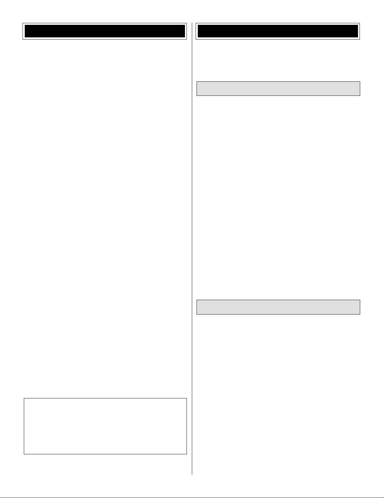
Building Stand
A building stand or cradle comes in handy during the build.
We use the Robart Super Stand II (ROBP1402) for all our
projects in R&D, and it can be seen in pictures throughout
this manual.
IMPORTANT BUILDING NOTES
• When you see the term test fi t in the instructions, it means
that you should fi rst position the part on the assembly
without using any glue, then slightly modify or custom fi t
the part as necessary for the best fi t.
• Whenever the term glue is written you should rely upon
your experience to decide what type of glue to use. When
a specifi c type of adhesive works best for that step, the
instructions will make a recommendation.
• Whenever just epoxy is specifi ed you may use either
30-minute (or 45-minute) epoxy or 6-minute epoxy. When
30-minute epoxy is specifi ed it is highly recommended that
you use only 30-minute (or 45-minute) epoxy, because you
will need the working time and/or the additional strength.
• Photos and sketches are placed before the step they
refer to. Frequently you can study photos in following steps
to get another view of the same parts.
• The stabilizer and wing incidences and engine thrust
angles have been factory-built into this model. However,
some technically-minded modelers may wish to check these
measurements anyway. To view this information visit the web
site at www.greatplanes.com and click on “Technical Data.”
Due to manufacturing tolerances which will have little or no
effect on the way your model will fl y, please expect slight
deviations between your model and the published values.
To locate a hobby dealer, visit the Hobbico web site at www.
greatplanes.com. Choose “Where to Buy” and follow the
instructions provided on the page to locate a U.S., Canadian
or International dealer.
Parts may also be ordered directly from Hobby Services by
calling (217) 398-0007, or via facsimile at (217) 398-7721,
but full retail prices and shipping and handling charges will
apply. Illinois and Nevada residents will also be charged
sales tax. If ordering via fax, include a Visa
number and expiration date for payment.
Mail parts orders and payments by personal check to:
Hobby Services
3002 N Apollo Drive, Suite 1
Champaign IL 61822
Be certain to specify the order number exactly as listed in the
Replacement Parts List. Payment by credit card or personal
check only; no C.O.D.
If additional assistance is required for any reason contact
Product Support by e-mail at productsupport@greatplanes.
com, or by telephone at (217) 398-8970.
REPLACEMENT PARTS LIST
Order No. Description
GPMA3390
GPMA3391
GPMA3392
GPMA3393
GPMA3394
GPMA3395
GPMA3396
GPMA3397
GPMA3398
NOTE
Fuselage
Wing Set
Tail Set
Canopy/Hatch
Cowl
Landing Gear
Wheel Pants
Wing Tube
Decal
Full-size plans are not available.
You can download a copy of this
manual at www.greatplanes.com.
®
or MasterCard
®
5
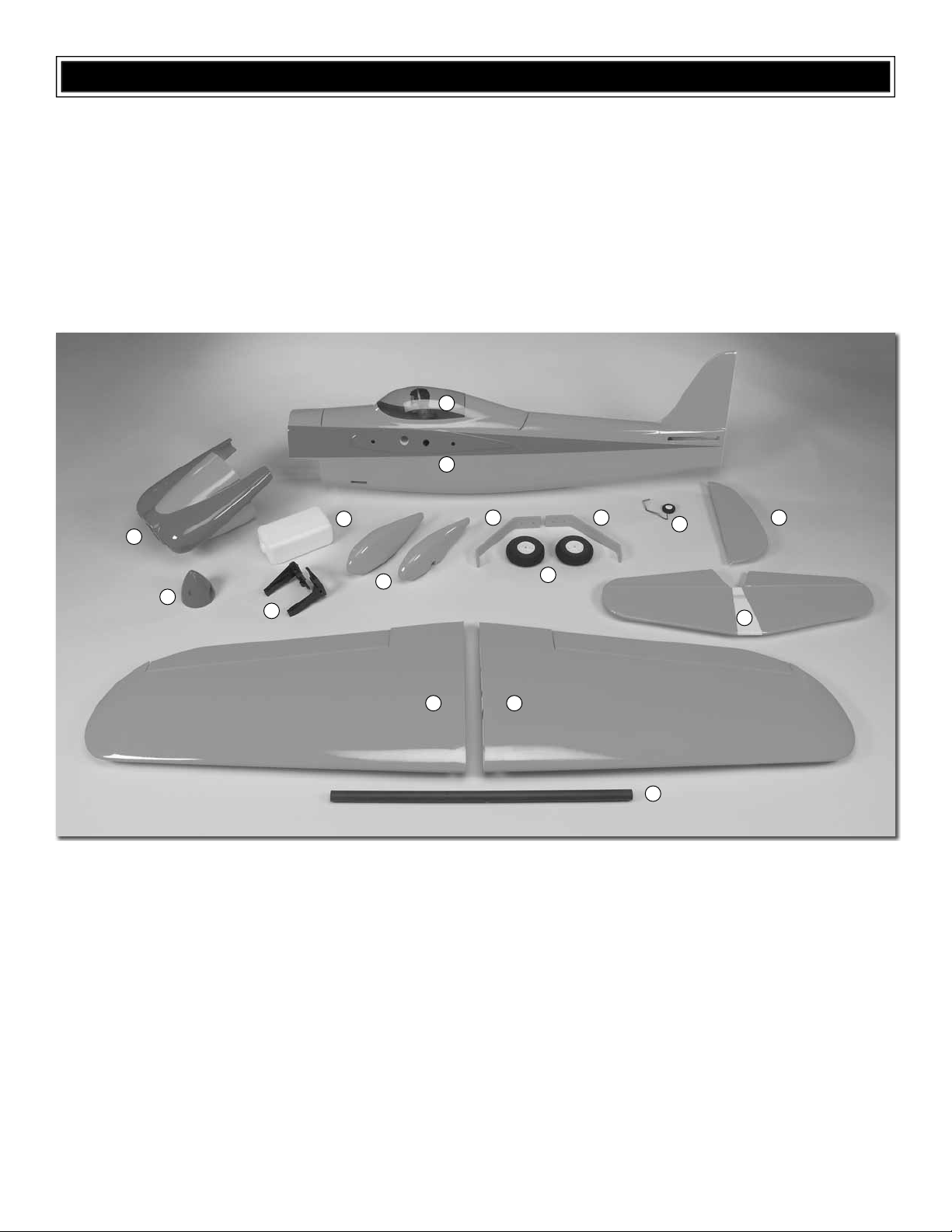
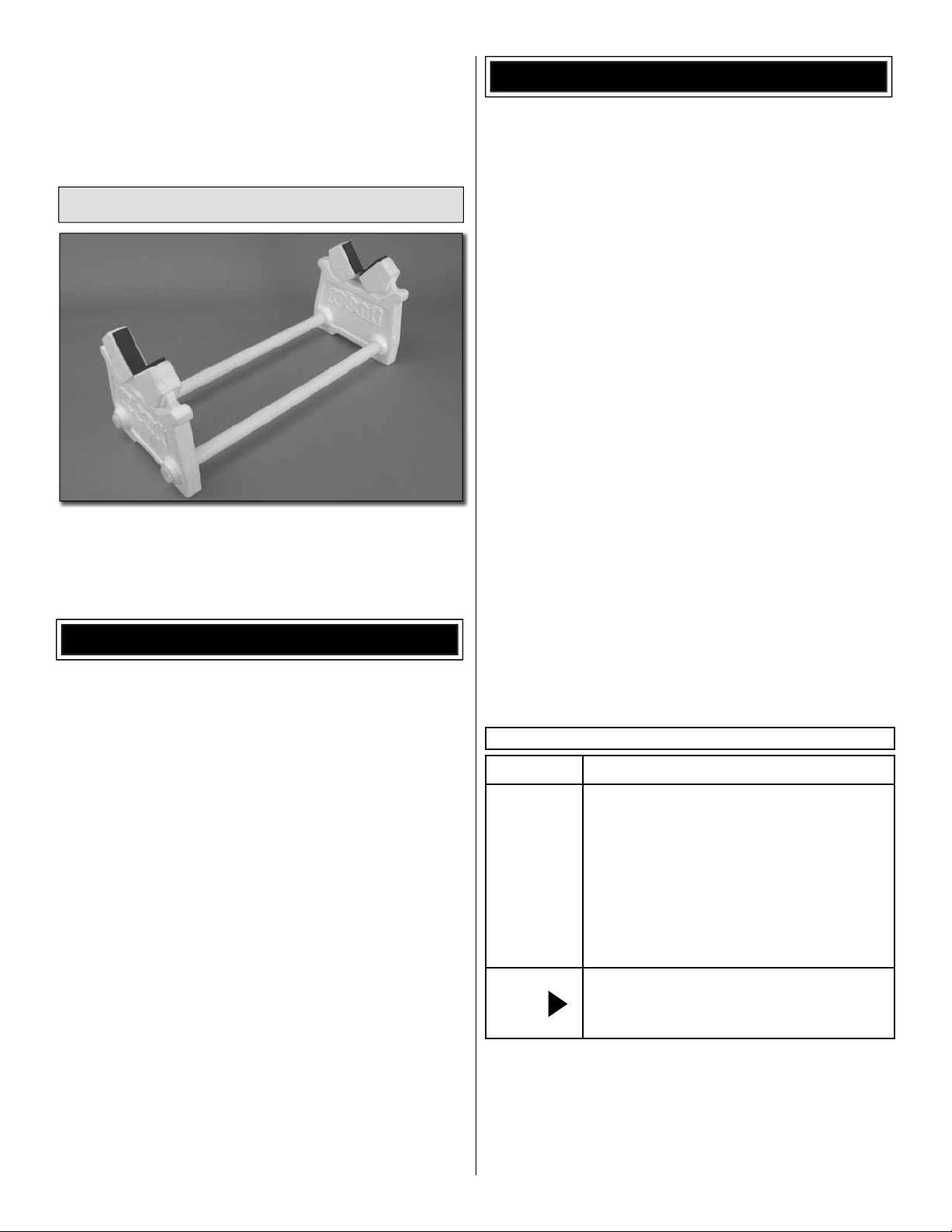
KIT INSPECTION
Before starting to build, take an inventory of this kit to make sure it is complete, and inspect the parts to make sure they
are of acceptable quality. If any parts are missing or are not of acceptable quality, or if you need assistance with assembly,
contact Product Support.
Great Planes Product Support
3002 N Apollo Drive, Suite 1
Champaign, IL 61822
Telephone: (217) 398-8970, ext. 5
Fax: (217) 398-7721
E-mail: airsupport@greatplanes.com
1
2
5
3
4
7
6
13 13
1. Canopy/Hatch
2. Fuselage
3. Cowl
4. Spinner
5. Fuel Tank
6. Engine Mount Halves
7. Wheel Pants (2)
9
8. Main Landing Gear (2)
9. Main Wheels (2)
10. Tail Wheel Assembly
11. Rudder
12. Horizontal Stabilizer
13. Wing Halves
14. Wing Joiner Tube
88
10
14
11
12
6
PREPARATIONS
❏ 1. If you have not done so already, remove the major parts
of the kit from the box and inspect for damage. If any parts
are damaged or missing, contact Product Support at the
address or telephone number listed in the “Kit Inspection”
section on page 6.
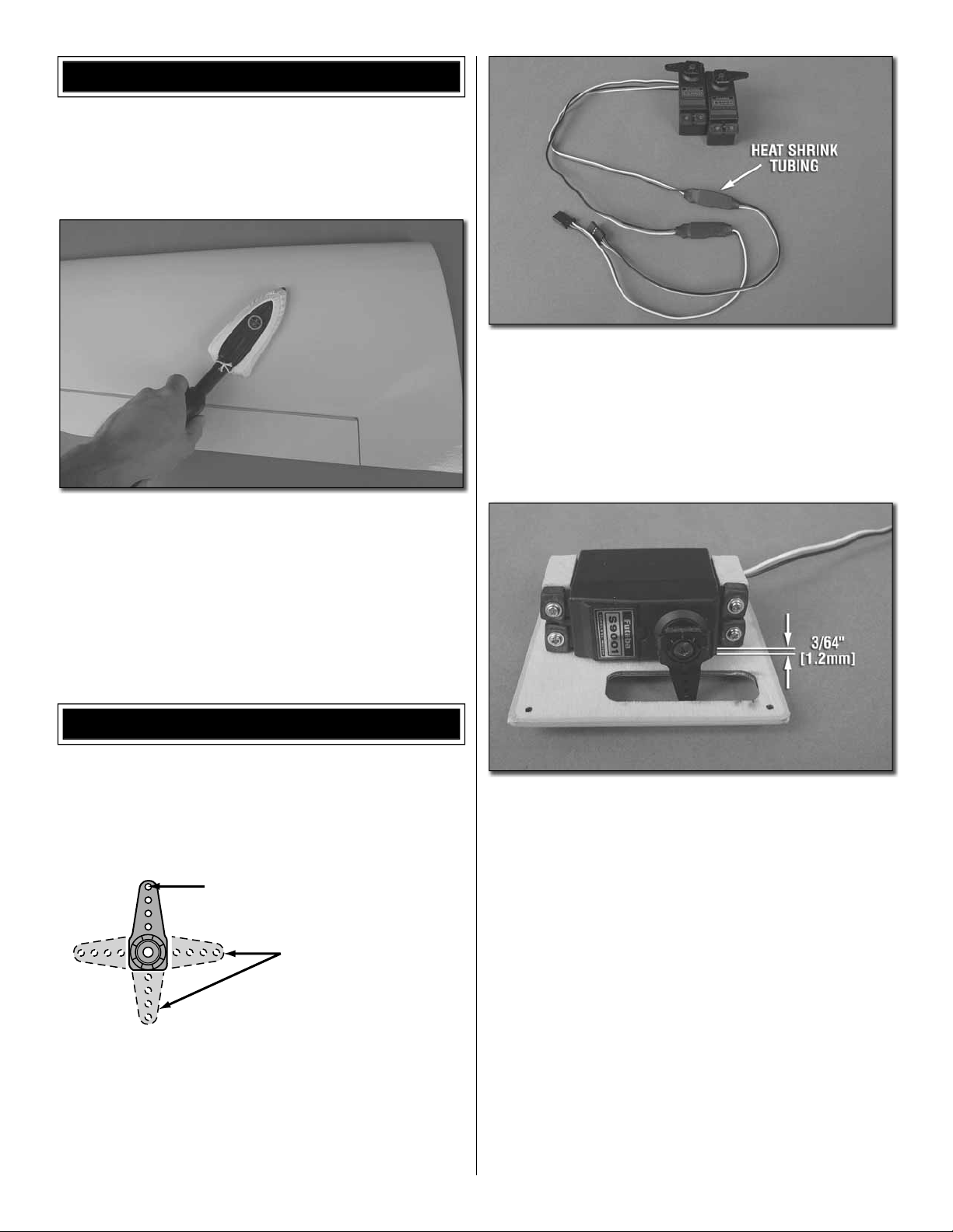
❏ 2. Remove the tape and separate all the control surfaces.
Use a covering iron with a covering sock on high heat to
tighten the covering if necessary. Apply pressure over sheeted
areas to thoroughly bond the covering to the wood.
❏ 2. Attach a 6" [152mm] servo extension to each aileron
servo and secure the connector using 1-1/2" [38mm] pieces
from the included heat shrink tubing. Center the servos with
your radio system and install the servo arms to the servos
perpendicular to the servo cases as shown. Be sure to
reinstall the servo arm screws into the servos.
ASSEMBLE THE WINGS
Before completing this section, confi rm that the servos that
you will be using will properly fi t between the servo mounting
blocks on the aileron servo hatch covers. Make adjustments
as necessary for your brand servos. A razor saw or hobby
knife can be used to trim the blocks if necessary.
5/64" [2mm]
CUT OFF UNUSED ARMS
❏ 1. Cut three arms from a four-armed servo arm for each
aileron servo. Enlarge the outer hole of each remaining arm
with a 5/64" [2mm] drill bit.
❏ 3. Position the servos against the underside of the aileron
servo hatch covers between the mounting blocks. Shim
the servo away from the hatch cover approximately 3/64"
[1.2mm] (a business card folded in thirds works well for this).
Drill 1/16" [1.6mm] holes through the mounting tabs on the
servo cases into the blocks. Thread a servo mounting screw
(included with the servo) into each hole and back it out. Apply
a drop of thin CA to each hole to harden the wood. When the
CA has dried, install the servos onto the hatch covers using
the hardware supplied with the servos.
7
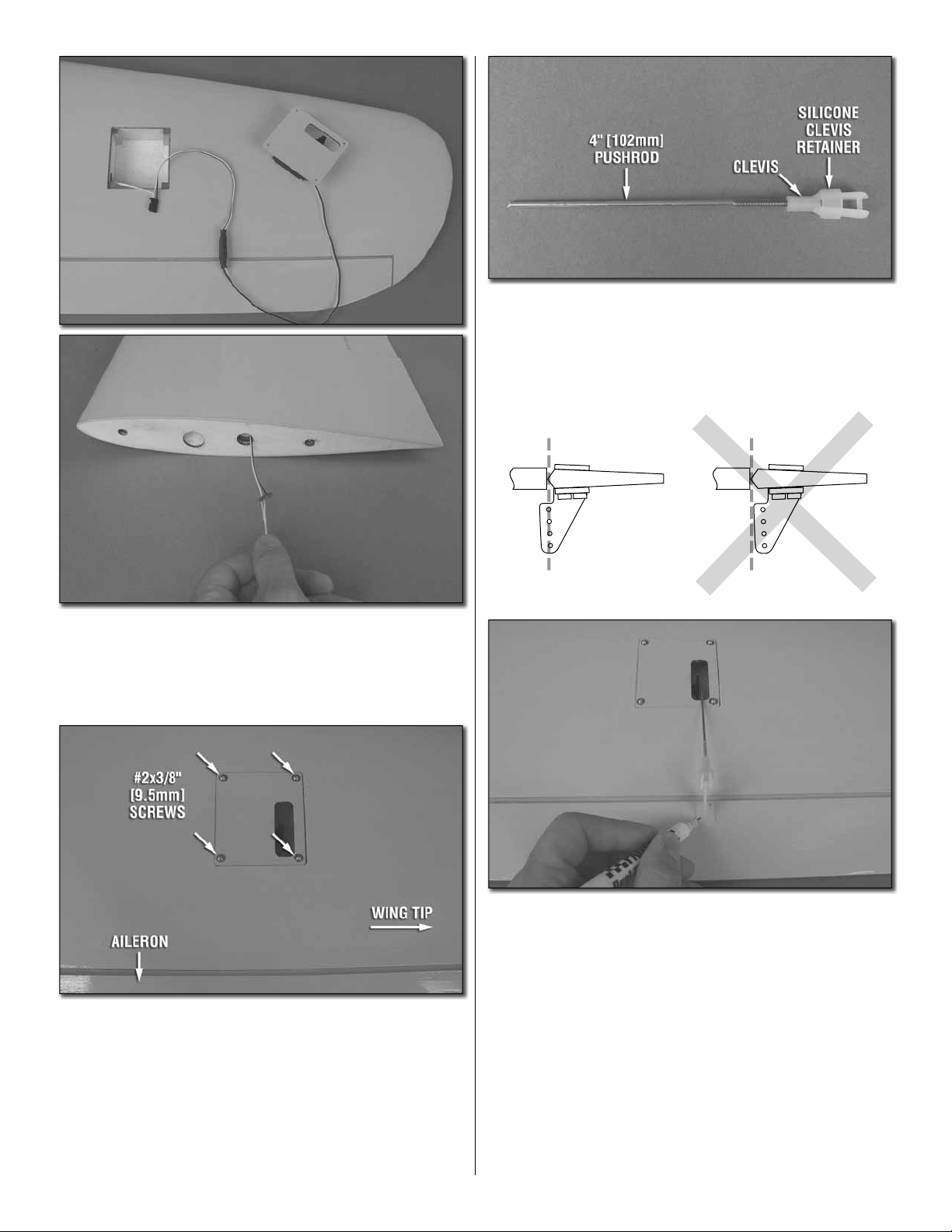
❏ 4. Use the strings taped inside the aileron servo hatches
to pull the servo leads through the wing.
❏ 6. Thread a nylon clevis 20 complete turns onto each 4"
[102mm] pushrod. Slide a silicone clevis retainer onto each
clevis and connect the clevises to the outer holes of two
control horns.
CORRECT INCORRECT
Hinge Line Hinge Line
❏ 5. Position the aileron servo hatch covers in place and drill
a 1/16" [1.6mm] hole through the mounting holes and into
the hatch mounting blocks. Thread a #2 x 3/8" [9.5mm] selftapping screw into each hole and back it out. Apply a drop
of thin CA to each hole to harden the wood surrounding the
hole. Install the hatch covers to the wings using eight #2 x
3/8" [9.5mm] self-tapping screws and eight #2 fl at washers.
❏ 7. Position the control horns over the plywood plates in
the ailerons (if you cannot see them, hold the aileron at a
shallow angle in good lighting or use a small pin to puncture
the covering) using the position of the servo arms as a
guide. Align the holes in the control horns directly over the
aileron hinge line and mark the location of the control horn
mounting holes.
❏ 8. Drill 1/16" [1.6mm] holes at the marks you made
through the plywood plates. Do not drill all the way through
the ailerons! Thread a #2 x 1/2" [13mm] self-tapping screw
through each hole and back it out. Apply a couple drops of
thin CA glue to each hole to harden the wood. When the glue
has dried, install the control horns onto the ailerons using
four #2 x 1/2" [13mm] self-tapping screws.
8
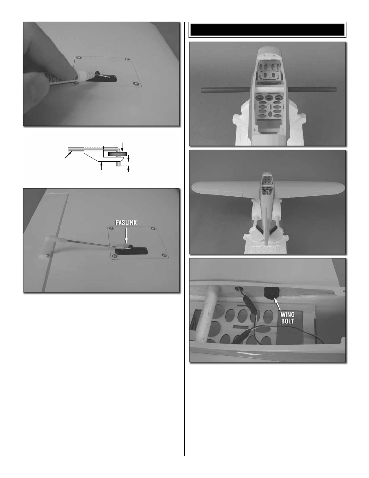
2-56 (.074")
Pushrod Wire
FasLink
ASSEMBLE THE TAIL SECTION
Servo Horn
1/16"
❏ 9. Use tape or a small clamp to hold the ailerons in the
neutral position. Make a mark on the pushrods where they
cross the outer holes in the servo arms. Make a 90° bend at
the mark on the pushrod and cut off the excess pushrod 1/4"
[6mm] beyond the bend. Attach the pushrods to the servo
arms using nylon FasLinks. Thread the clevises up or down
on the pushrods as necessary to center the ailerons with the
servo arms centered. When satisfi ed, slide the silicone clevis
retainers to the ends of the clevises to secure them.
❏ 1. Insert the wing tube into the fuselage and center its
position. Slide the wing panels onto the tube and feed the
aileron servo leads through the mating holes in the fuse.
Tighten the wing panels against the fuse using the two nylon
wing bolts.
9
and right and align it with the wing panels. Use denatured
alcohol to clean up any excess epoxy. Allow the epoxy to
cure undisturbed.
❏ 4. When the epoxy has cured, the wing panels can be
removed from the fuselage and set aside. They will not be
needed again until it is time to set up the control throws.
1"
1"
3/4"
❏ 5. Cut the included 2" x 9" [51mm x 229mm] CA hinge
strip into 3/4" x 1" [19mm x 25mm] individual hinges. Clip the
corners of each hinge to make them easier to insert into the
hinge slots.
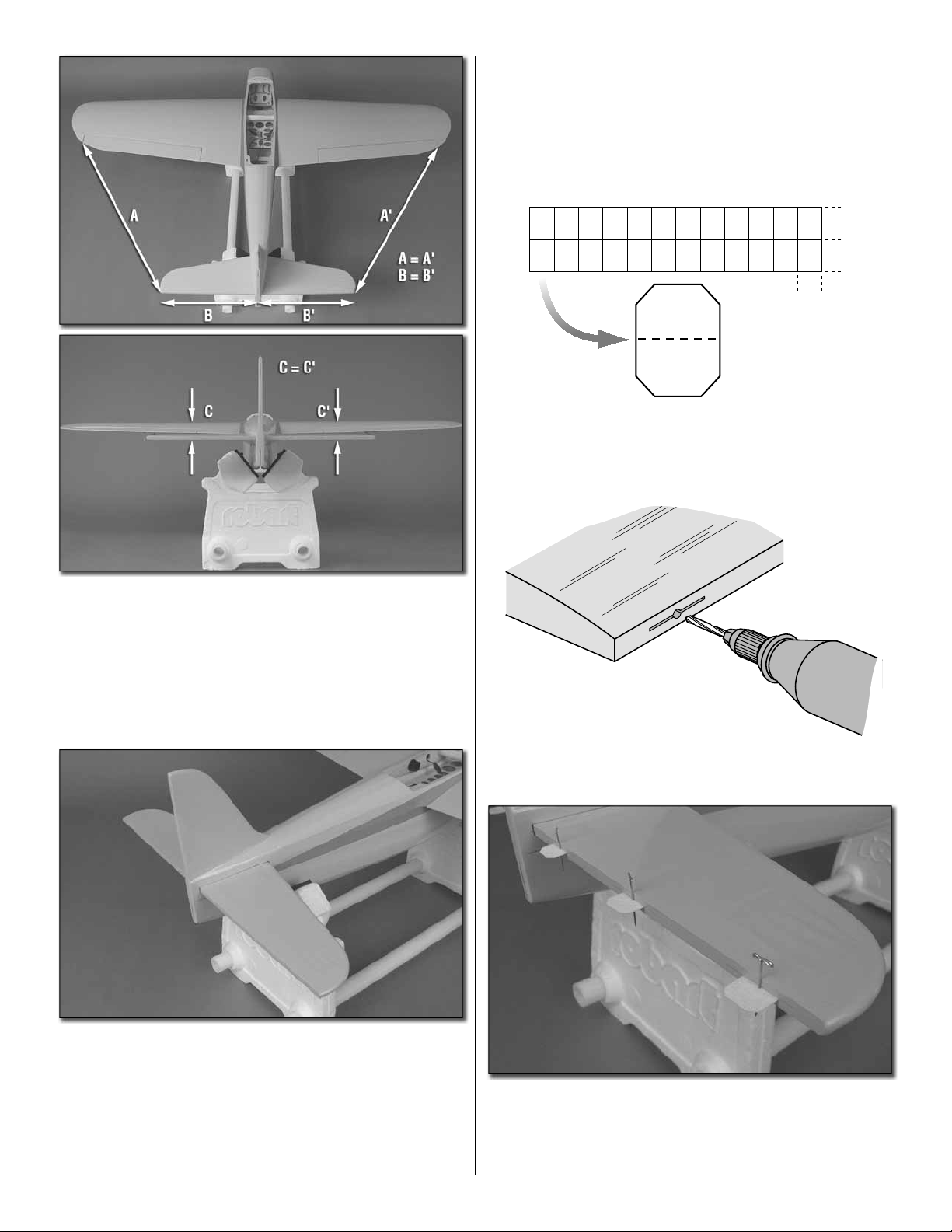
❏ 2. Test fi t the horizontal stabilizer into the stab slot at
the aft end of the fuselage (without glue). Center the stab left
and right in the fuse. Measure the distance from the stab tips
to the wing tips and make the measurements equal. Now,
stand behind the model approximately 5-6 ft [1.5-1.8m] and
confi rm that the stab and wings are parallel. If not, weight
can be added to one side to bring them parallel, or the stab
can be taped to the fi n to pull it parallel with the wing.
❏ 3. After you have determined if any weight will need to
be added during the gluing process, remove the stab from
the fuse. If necessary, lightly sand away any excess paint
from inside the stab slot. Mix up a batch of 30-minute epoxy
and coat the stab slot as well as the exposed wood of the
stabilizer (coating the stab slot will require additional cleanup
after inserting the stab into the fuse. However, it will make a
stronger glue joint). Slide the stab into the fuse, center it left
DRILL A 3/32" HOLE,
1/2" DEEP, IN CENTER
OF HINGE SLOT
❏ 6. Drill a 3/32" [2.4mm] hole 1/2" [13mm] deep into the
center of each hinge slot in the stab and elevator halves.
❏ 7. Test fi t a CA hinge into each of the hinge slots in the
stab and elevator halves. If necessary, enlarge the slots with
a hobby knife. When satisfi ed with the fi t, insert a CA hinge
halfway into each hinge slot in the wing panel. Push a pin
through the middle of each hinge to keep them centered.
10
 Loading...