

Page 1
WARRANTY
Great Planes
®
Model Manufacturing Co. guarantees this kit to be free from defects in both material and workmanship at the date of
purchase.This warranty does not cover any component parts damaged by use or modification. In no case shall Great Planes' liability
exceed the original cost of the purchased kit. Further, Great Planes reserves the right to change or modify this warranty without notice.
In that Great Planes has no control over the final assembly or material used for final assembly, no liability shall be assumed nor
accepted for any damage resulting from the use by the user of the final user-assemb led product.By the act of using the user-assembled
product, the user accepts all resulting liability.
If the buyer is not prepared to accept the liability associated with the use of this product, the buyer is advised to return this
kit immediately in new and unused condition to the place of purchase.
READ THROUGH THIS MANUAL BEFORE
STARTING CONSTRUCTION. IT CONTAINS
IMPORTANT WARNINGS AND INSTRUCTIONS
CONCERNING THE ASSEMBLY AND USE OF
THIS MODEL.
GPMZ0282 for GPMA1326 V1.0© Copyright 2003
Champaign, Illinois
(217) 398-8970, Ext 5
airsupport@greatplanes.com
INSTRUCTION MANUAL
Wingspan: 68 in [1727mm]
Wing Area: 743 sq in [48 dm2]
Weight: 11-1/4 - 12-1/4 lbs [5103 - 5557 g]
Wing Loading: 34.9 - 38 oz/sq ft [106 - 116 g/dm2]
Length: 45 in [1143mm]
Radio: 4 channel with six servos
Engine: .91 - 1.08 cu in [15cc - 18cc] two-stroke,1.20 cu in [20 cc] four-stroke
Page 2
INTRODUCTION................................................................2
Scale Competition..............................................................3
SAFETY PRECAUTIONS..................................................3
DECISIONS YOU MUST MAKE ........................................4
Radio Equipment ................................................................4
Engine Recommendations.................................................4
ADDITIONAL ITEMS REQUIRED.....................................4
Hardware and Accessories................................................4
Adhesives and Building Supplies.......................................4
Covering Tools....................................................................4
Optional Supplies and Tools...............................................4
IMPORTANT BUILDING NOTES.......................................4
ORDERING REPLACEMENT PARTS ...............................5
KIT CONTENTS .................................................................6
PREPARATIONS................................................................7
ASSEMBLE THE FUSELAGE STAND ..............................7
BUILD THE WING..............................................................8
Install the Ailerons..............................................................8
Install the Aileron Servos and Pushrods............................9
Join the Wings..................................................................10
Install the Landing Gear...................................................11
Install the Belly Pan..........................................................13
ASSEMBLE THE FUSELAGE.........................................14
Install the Engine and Throttle Servo...............................14
Install the Fuel Tank .........................................................17
Install the Cowl Ring, Cowl and Dummy Engine..............18
Mount the Stab, Elevator, Rudder and Tailwheel .............22
Install the Elevator and Rudder Servos, Radio System
and Pushrods.........................................................24
Finishing Touches.............................................................28
GET THE MODEL READY TO FLY..................................28
Check the Control Directions ...........................................28
Set the Control Throws.....................................................29
Balance the Model (C.G.).................................................29
Balance the Model Laterally.............................................30
PREFLIGHT.....................................................................30
ENGINE SAFETY PRECAUTIONS.................................31
AMA SAFETY CODE ......................................................31
CHECKLIST.....................................................................32
FLYING.............................................................................32
Fuel Mixture Adjustments.................................................32
Takeoff..............................................................................33
Flight.................................................................................33
Aerobatics ........................................................................33
Engine Out Situation........................................................33
Landing.............................................................................33
ENGINE MOUNT TEMPLATES.......................................35
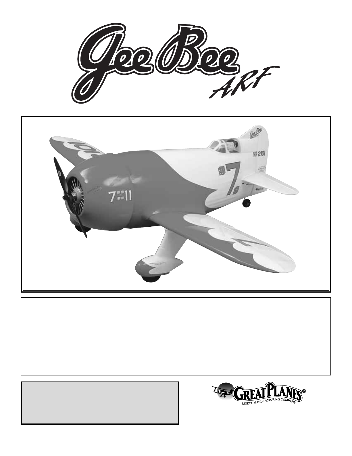
Since its introduction, the Gee Bee has caught the
imagination of the full-scale aviation enthusiast and modelers
alike.The full-scale plane was notorious for its unpredictable
flight characteristics. Great Planes is proud to introduce our
version that has the characteristic look of the full scale Gee
Bee without the unpredictable flight characteristics. You will
enjoy flying this impressive model and showing off its
aerobatic capabilities to everyone at the field.
For the latest technical updates or manual corrections to the
Gee Bee visit the web site listed below and select the Great
Planes Gee Bee ARF.If there is new technical information or
changes to this model, a “tech notice” box will appear in the
upper left corner of the page.
http://www.greatplanes.com/airplanes/index.html
Though the Great Planes Gee Bee is an ARF and may not
have the same level of detail as an “all-out” scratch-built
competition model, it is a scale model nonetheless and is
therefore eligible to compete in the Fun Scale class in AMA
competition. (We receive many favorable reports of Great
Planes ARFs in scale competition!) In Fun Scale, the “builder
of the model” rule does not apply. To receive the five points
for scale documentation, the only proof required that a full
size aircraft of this type in this paint/markings scheme did
exist is a single sheet such as a kit box cover from a plastic
model, a photo, or a profile painting, etc. If the photo is in
black and white, other written documentation of color must
be provided.Contact the AMA for a rule book with full details.
If you would like photos of the full-size Gee Bee for scale
documentation, or if you would like to study the photos to
add more scale details, photo packs are available from:
Bob's Aircraft Documentation
3114 Y uk on Av e
Costa Mesa, CA 92626
Telephone: (714) 979-8058
Fax:(714) 979-7279
e-mail: www.bobsairdoc.com
1. Your Gee Bee should not be considered a toy, but rather a
sophisticated, working model that functions very much like a fullsize airplane. Because of its performance capabilities, the Gee
Bee, if not assembled and operated correctly, could possibly
cause injury to yourself or spectators and damage to property.
2.You must assemble the model according to the instructions.
Do not alter or modify the model, as doing so may result in an
unsafe or unflyable model. In a few cases the instructions may
differ slightly from the photos. In those instances the written
instructions should be considered as correct.
3.You must take time to build straight, true and strong.
PRO TECT YOUR MODEL,YOURSELF
& OTHERS...FOLLOW THESE
IMPORTANT SAFETY PRECAUTIONS
Scale Competition
INTRODUCTION
TABLE OF CONTENTS
2
Page 3
4. You must use an R/C radio system that is in first-class
condition and a correctly sized engine and components (fuel
tank, wheels, etc.) throughout the building process.
5.You must correctly install all R/C and other components so
that the model operates correctly on the ground and in the air .
6.You must check the operation of the model before every
flight to insure that all equipment is operating and that the
model has remained structurally sound. Be sure to check
clevises or other connectors often and replace them if they
show any signs of wear or fatigue.
7. If you are not already an experienced R/C pilot, you
should fly the model only with the help of a competent,
experienced R/C pilot.
8.While this kit has been flight tested to exceed normal use,
if the plane will be used for extremely high stress flying, such
as racing, the modeler is responsible for taking steps to
reinforce the high stress points.
Remember:Take y our time and follow the instructions to
end up with a well-built model that is straight and true.
If you have not flo wn this type of model bef ore, we recommend
that you get the assistance of an experienced pilot in your R/C
club for your first flights.If you're not a member of a club, your
local hobby shop has information about clubs in your area
whose membership includes experienced pilots.
In addition to joining an R/C club, we strongly recommend y ou
join the AMA (Academy of Model Aeronautics). AMA
membership is required to fly at AMA sanctioned clubs.There
are over 2,500 AMA chartered clubs across the country.
Among other benefits, the AMA provides insurance to its
members who fly at sanctioned sites and events .Additionally,
training programs and instructors are available at AMA club
sites to help you get started the right way. Contact the AMA at
the address or toll-free phone number below:
Academy of Model Aeronautics
5151 East Memorial Drive
Muncie, IN 47302-9252
Tele. (800) 435-9262
Fax (765) 741-0057
Or via the Internet at:
http://www.modelaircraft.org
This is a partial list of items required to finish the Gee Bee
that may require planning or decision making before starting
to build.
4-Channel transmitter and a minimum 4-channel receiver .(A
6-channel computer radio transmitter and receiver ma y offer
some mixing functions desirable for this model).
6 - servos, minimum 40 oz-in torque
2 - 12" [305mm] servo extensions
2 - Y-harness connectors
1 - servo reverser for the two elev ator servos (only if you are
not able to mix two channels to mov e two servos in the same
direction with your computer radio.)
The recommended engine size range for the Gee Bee is .91
to 1.08 two-stroke or 1.20 four-stroke. If an engine in the
upper end of the size range is used, remember that this is a
scale model that is intended to fly at scale-like speeds, so
throttle management should be practiced.
In addition to the items listed in the “Decisions You Must
Make” section, following is the list of hardware and
accessories required to finish the Gee Bee. Order numbers
are provided in parentheses.
❏ Engine and suitable propellers
❏ 4-channel radio with 6 servos, minimum 40 oz-in torque
❏ 2 - 12" [300mm] servo extension (HCAM2711 for Futaba
®
)
❏ Y-har ness (HCAM2751 for Futaba)
❏ 1 - servo reverser for the two elevator servos (only if you
are not able to mix two channels to move two servos in
the same direction with your computer radio.)
❏ R/C foam rubber (1/4" [6mm] - HCAQ1000, or 1/2"
[13mm] - HCAQ1050)
❏ 3' [900mm] standard silicone fuel tubing (GPMQ4131)
❏ Fuel filler valve for glow fuel (GPMQ4160)
Hardware and Accessories
ADDITIONAL ITEMS REQUIRED
Engine Recommendations
Radio Equipment
DECISIONS YOU MUST MAKE
We, as the kit manufacturer, provide you with a top quality
kit and instructions, but ultimately the quality and flyability
of your finished model depends on how you build it;
therefore, we cannot in any way guarantee the
performance of your completed model and no
representations are expressed or implied as to the
performance or safety of your completed model.
3
Page 4

In addition to common household tools and hobby tools,
this is the “short list” of the most important items required to
build the Gee Bee.
Great Planes Pro™ CA and Epoxy glue
are recommended.
❏ 1 oz. [30g] Thin Pro CA (GPMR6002)
❏ 1 oz. [30g] Medium Pro CA+ (GPMR6008)
❏ Pro 30-minute epoxy (GPMR6047)
❏ Pro 6-minute epoxy (GPMR6045)
❏ R/C-56 canopy glue (JOZR5007)
❏ Microballoons (TOPR1090)
❏ Drill bits: 1/16" [1.6mm], 5/64" [2mm], 3/32" [2.4mm], 1/8"
[3.2mm], 9/64" [3.6mm], 5/32" [4mm], 3/16" [4.8mm],
1/4" [6.4mm]
❏ Stick-on segmented lead weights (GPMQ4485)
❏ 1 Hobby knife (HCAR0105)
❏ #11 blades (5-pack, HCAR0211)
❏ File
❏ Top Flite
®
MonoKote®sealing iron (TOPR2100)
❏ Top Flite Hot Sock
™
iron cover (TOPR2175)
❏ Top Flite MonoKote trim seal iron (TOPR2200)
❏ Top Flite MonoKote heat gun (TOPR2000)
❏ 2 oz. [57g] spray CA activator (GPMR6035)
❏ CA applicator tips (HCAR3780)
❏ CA debonder (GPMR6039)
❏ Epoxy brushes (6, GPMR8060)
❏ Mixing sticks (50, GPMR8055)
❏ Mixing cups (GPMR8056)
❏ Curved-tip canopy scissors for trimming plastic parts
(HCAR0667)
❏ Hobbico
®
Duster™, can of compressed air (HCAR5500)
❏ Masking tape (TOPR8018)
❏ Threadlocker thread locking cement (GPMR6060)
❏ Denatured alcohol (for epoxy clean up)
❏ Switch & Charge Jack Mounting Set (GPMM1000)
❏ Rotar y tool such as a Dremel
®
❏ Rotar y tool reinforced cut-off wheel (GPMR8200)
❏ Ser vo horn drill (HCAR0698)
❏ Dead Center
™
Engine Mount Hole Locator (GPMR8130)
❏ AccuThrow
™
Deflection Gauge (GPMR2405)
❏ CG Machine
™
(GPMR2400)
❏ Laser incidence meter (GPMR4020)
❏ Precision Magnetic Prop Balancer
™
(TOPQ5700)
• There are two types of screws used in this kit:
Sheet metal screws are designated by a number and a
length. For example #6 x 3/4" [19mm]
This is a number six screw that is 3/4" [19mm] long.
Machine screws are designated by a number, threads per
inch and a length. For example 4-40 x 3/4" [19mm]
This is a number four screw that is 3/4" [19mm] long
with forty threads per inch.
• When you see the term
test fit
in the instructions, it
means that you should first position the part on the
assembly without using any glue, then slightly modify or
custom fit
the part as necessar y for the best fit.
• Whenever the term
glue
is written you should rely upon
your experience to decide what type of glue to use.When a
specific type of adhesive works best for that step, the
instructions will make a recommendation.
• Whenever just
epoxy
is specified you may use
either
30-minute (or 45-minute) epoxy or6-minute epoxy. When
30-minute epoxy is specified it is highly recommended that
you use only 30-minute (or 45-minute) epoxy, because you
will need the working time and/or the additional strength.
• Photos and sketches are placed before the step they
refer to. Frequently you can study photos in following steps
to get another view of the same parts.
• The Gee Bee is factory-covered with Top Flite MonoKote
film.Should repairs ever be required, MonoK ote can be patched
with additional MonoKote purchased separately. MonoKote is
packaged in six-foot rolls, but some hobby shops also sell it by
the foot.If only a small piece of MonoKote is needed f or a minor
patch, perhaps a fellow modeler would give you some.
MonoKote is applied with a model airplane covering iron, but in
an emergency a regular iron could be used. A roll of MonoKote
includes full instructions for application.Following are the colors
used on this model and order numbers for six foot rolls.
Red – TOPQ0201
White – TOPQ0204
• The stabilizer and wing incidences and engine thrust
angles have been factory-built into this model. However,
some technically-minded modelers may wish to check these
measurements anyway.T o vie w this information visit the web
site at www.greatplanes.com and click on “Technical Data.”
Due to manufacturing tolerances which will have little or no
effect on the way your model will fly, please expect slight
deviations between your model and the published values.
IMPORTANT BUILDING NOTES
Optional Supplies and Tools
Covering T ools
Adhesives and Building Supplies
4
Page 5
5
If you have never worked with fiberglass there are a few
basic things you should be aware of:
1. When you are cutting into fiberglass, be sure you are
cutting the correct place. Unlike wood, you are not able to
go back and easily fix a mistake.
2.Whenever you are gluing a part to the inside of fiberglass
it is important to roughen the inside surface of the fiberglass
with 220-grit sandpaper. Then wipe the area with alcohol.
The molding process leaves a waxy residue that can pre v ent
a good bond between the glue and the parts being glued.
3. If you do not have a high-speed motor tool such as a
Dremel®tool, you should consider purchasing one or
borrowing one from a fellow modeler. This combined with a
fiberglass cut-off wheel is going to be extremely helpful in
the assembly process.
WARNING:The cowl, wheel pants and fuselage included in
this kit are made of fiberglass, the fibers of which may
cause eye, skin and respiratory tract irritation. Never blow
into a part to remove fiberglass dust, as the dust will blow
back into your eyes.Always wear safety goggles, a particle
mask and rubber gloves when grinding, drilling and sanding
fiberglass parts. Vacuum the parts and the work area
thoroughly after working with fiberglass parts.
IMPORTANT INFORMATION ABOUT WORKING WITH FIBERGLASS
To order replacement par ts for the Great Planes Gee Bee ARF, use the order numbers in the Replacement Parts List
that follows. Replacement par ts are available only as listed. Not all parts are available separately (an aileron cannot be
purchased separately, but is only available with the wing kit).Replacement par ts are not available from Product Support,
but can be purchased from hobby shops or mail order/Internet order firms. Hardware items (screws, nuts, bolts) are also
available from these outlets. If you need assistance locating a dealer to purchase par ts, visit www.greatplanes.com and
click on “Where to Buy.” If this kit is missing parts, contact Product Support.
Replacement Parts List
Order Number Description How to Purchase
Missing pieces ................................................Contact Product Support
Instruction manual...........................................Contact Product Support
Full-size plans.................................................Not available
Kit parts listed below .......................................Hobby Supplier
GPMA2390 ...........Wing Kit
GPMA2391 ...........Fuselage Kit
GPMA2392 ...........Stabilizer Set
GPMA2393 ...........Rudder
GPMA2394 ...........Landing Gear Set
GPMA2395 ...........Wheel Pants
GPMA2396 ...........Canopy
GPMA2397 ...........Cowl
GPMA2398 ...........Decal Set
ORDERING REPLACEMENT PARTS
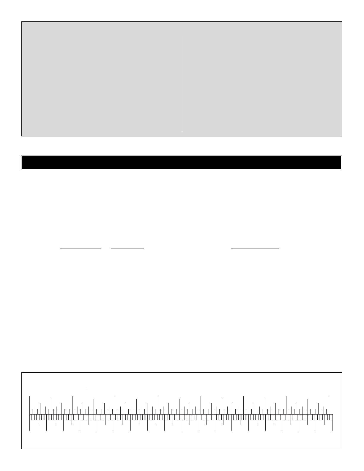
0" 1" 2" 3" 4" 5" 6" 7"
0 10 20 30 40 50 60 70 80 90 100 110 120 130 140 150 160 170 180
Inch Scale
Metric Scale
To convert inches to millimeters, multiply inches by 25.4
Page 6
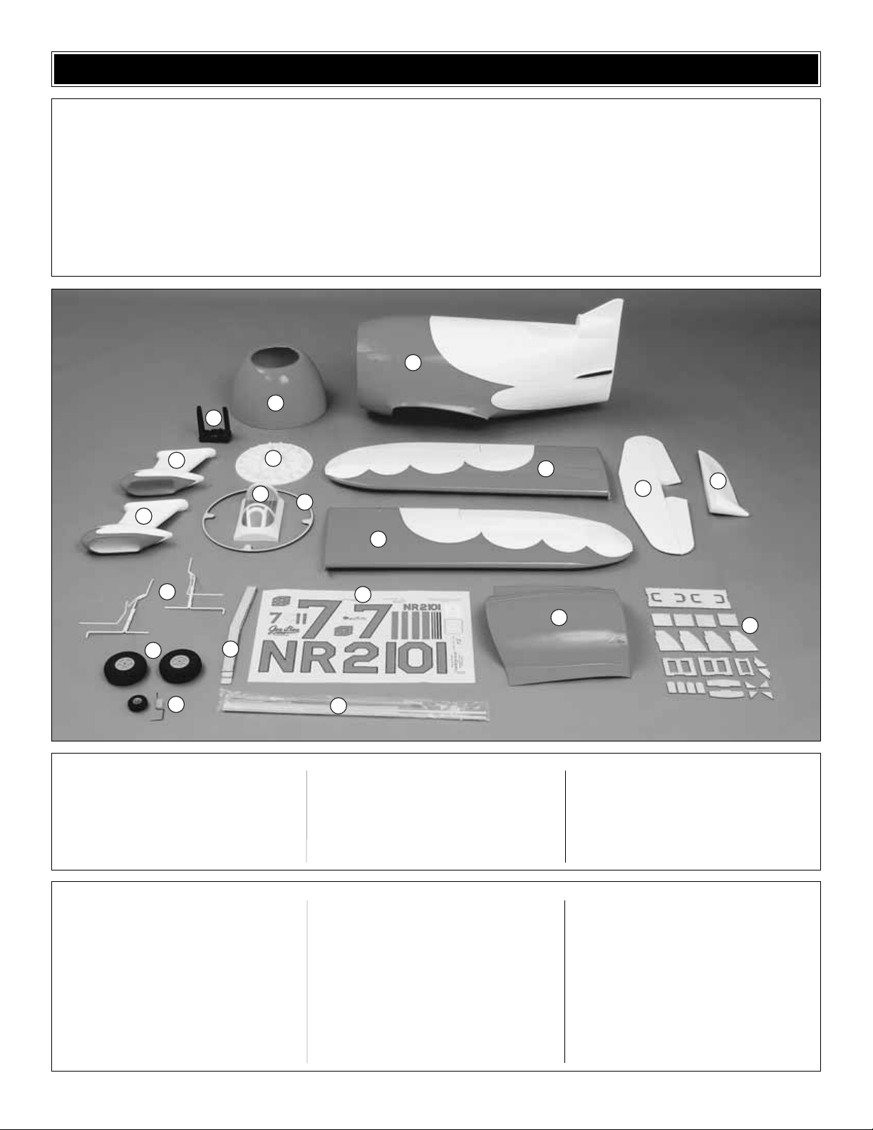
6
1 Fuselage
2 Cowl
3 Right Wing and Aileron
4 Left Wing and Aileron
5 Stabilizer and Elevators
6 Rudder
7 Dummy Engine
8 Engine Mount
9 Wheel Pants
10 Cowl Ring (2)
11 Canopy
12 Wire Landing Gear
13 Main Wheels
14 Tail Wheel Assembly
15 Wing Joiners
16 Decal Sheet (2)
17 Pushrods
18 Belly Pan
19 Plywood Ser vo Trays, Battery/Receiver
Tray, and Cowl Mounting Parts
(1) .60 -1.20 Engine mount (left)
(1) .60 -1.20 Engine mount (right)
(1) Brass EZ Connect
(4) 6-32 Blind Nuts
(4) 8-32 Blind Nuts
(2) 1/4-20 Blind Nuts
(5) Nylon Control Horn, Large
(1) Nylon Bearing for tail wheel wire
(2) 1/4 -20 Nylon bolts
(5) Nylon Clevis
(2) Flat Nylon landing Gear Straps (1tree of 4)
(1) Nylon retainer
(1) 2x9 Hinge material
(6) Faslink
(5) Silicone Clevis Keeper
(4) 6-32 Set Screw
(2) 6-32 x 1/4" SHCS
(2) 4-40 Set Screw
(1) 4-40 x 1/4" SHCS
(4) 6-32 x 1/2" SHCS
(8) #4 x 5/8 SMS
(8) 8-32 x 1" SHCS
(34) #2 x 1/2" SMS
(3) Heat Shrink Tube
(2) 1/8 Wheel Collar
(4) 5/32 Wheel Collar
(3) .074 x 17 1/2" wire
(3) .074 x 6" wire
(4) #6 Flat Washer
(8) #8 Lock washer
(8) #8 Flat Washer
(2) Axles
(4) 3 x 51 x 51mm Plywood Plate
(4) 3mm Plywood Cowl Mount Tabs
(18) 1/8" x 3/4" Aluminum Tube
(1) Pilot
Kit Contents (Photographed)
Kit Contents (Not Photographed)
Before starting to build, take an inventory of this kit to make sure it is complete and inspect the parts to make sure they
are of acceptable quality. If any parts are missing or are not of acceptable quality, or if you need assistance with assembly ,
contact Product Support. When repor ting defective or missing parts, use the part names exactly as they are written in
the Kit Contents list on this page.
Great Planes Product Support
3002 N. Apollo Drive, Suite 1
Champaign, IL 61822
Telephone: (217) 398-8970
Fax: (217) 398-7721
E-mail: airsupport@greatplanes.com
KIT INSPECTION
1
2
8
9
9
12
13
14
15
11
7
3
5
6
10
4
16
18
19
17
Page 7
1. If you have not done so already, remove the major parts
of the kit from the box and inspect for damage. If any parts
are damaged or missing, contact Product Support at the
address or telephone number listed in the “Kit Inspection”
section on page 6.
2. Remove the tape and separate the ailerons and flaps from
the wing and the elevators from the stab. Use a covering iron
with a covering sock on high heat to tighten the covering if
necessary .Apply pressure over sheeted areas to thoroughly
bond the covering to the wood.
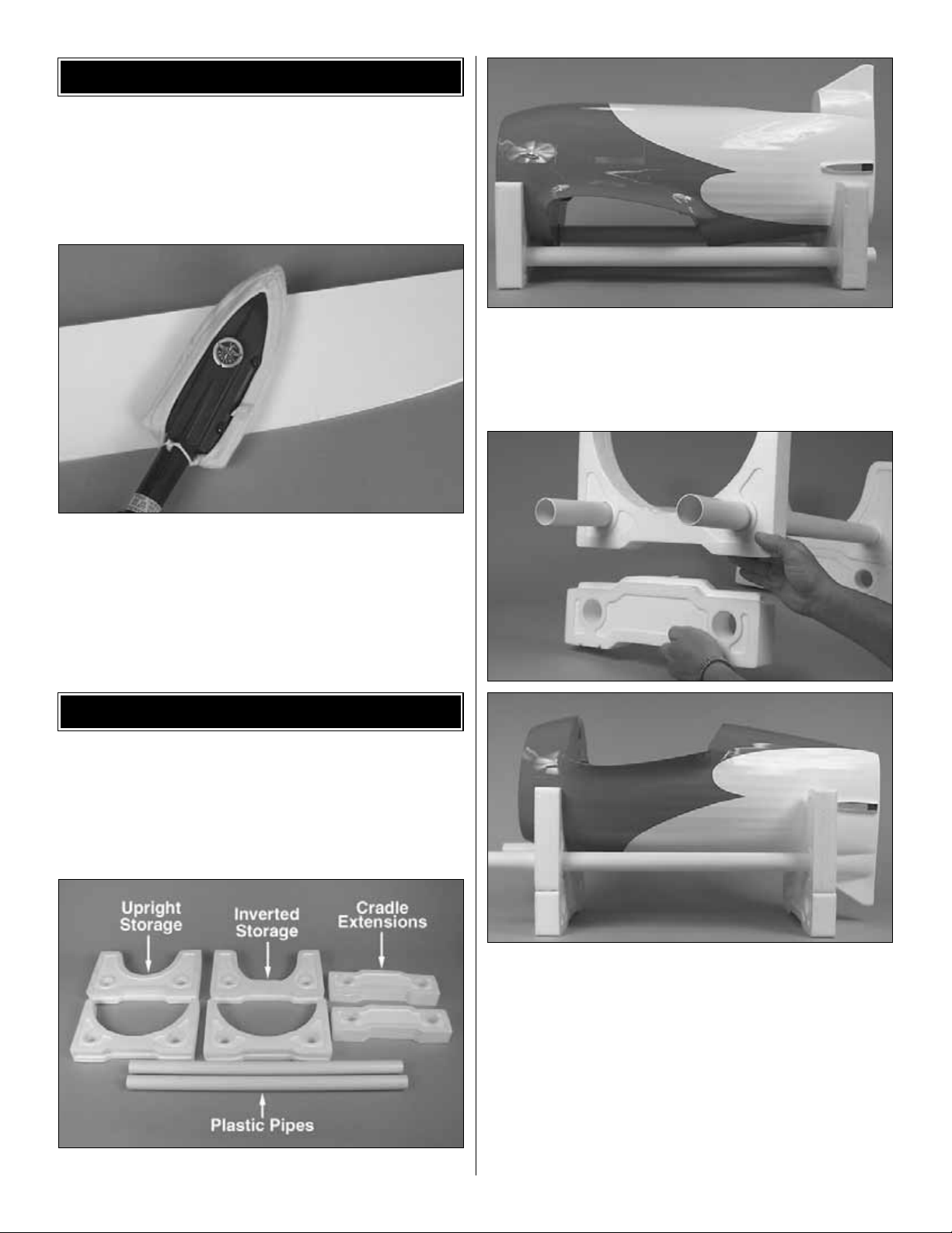
Because of the awkward shape of the Gee Bee we have
designed a very useful foam cradle for the model. As
you have already seen it was used in the shipping box,
can be used as an assembly stand and for transporting
the Gee Bee to the flying field!
❏ 1. Locate the components of the foam cradle.
❏ 2.Slide the foam part with the large oval onto one end of
each of the two plastic pipes. Slide the par t with the small
oval on the opposite end. This configuration will hold the
Gee Bee upright on your workbench and work well for
transporting your Gee Bee too!
❏ 3. For working on the Gee Bee inverted on the bench,
remove the foam parts from the pipes and replace them with
the other two large foam parts. Insert the small cradle
extensions onto the bottom of the foam parts.This will provide
the additional height required to provide clearance for the
vertical fin.The cradle extensions fit snugly into the foam cradle
but may loosen with use.You may wish to consider gluing them
together with epoxy for a more permanent installation.
Note: At the time this manual was written we had not yet
received the foam cradle that is included with this kit so we
used a different stand for our construction photographs.
ASSEMBLE THE FUSELAGE ST AND
PREPARATIONS
7
Page 8
Do the right wing first so your work matc hes the photos
the first time through.You can do one wing at a time , or
work on them together.
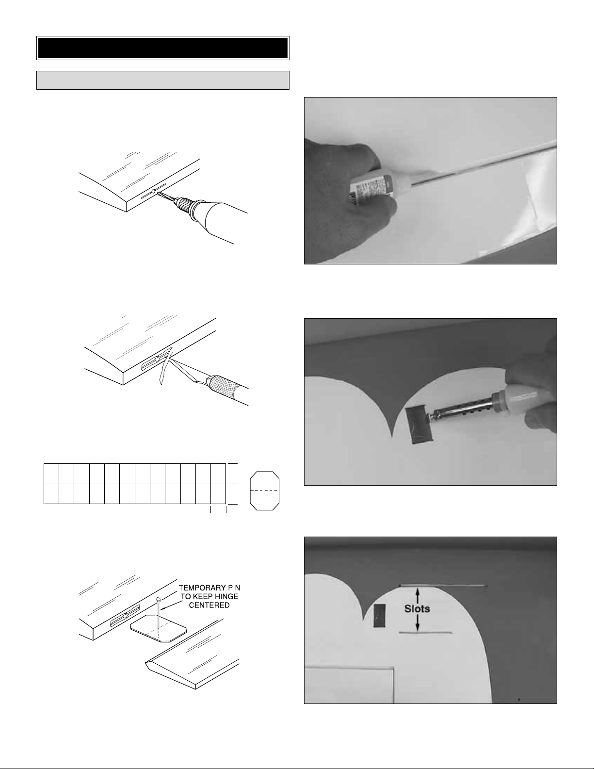
❏❏1. Drill a 3/32" hole, 1/2" deep in the center of each
hinge slot to allow the CA to “wick” in. Follow-up with a #11
blade to clean out the slots. Hint: If you have one, use a
high-speed rotary tool to drill the holes.
❏❏2. Use a sharp #11 blade to cut a strip of covering
from the hinge slots in the wing and aileron.
❏❏3.Cut three 3/4" x 1" hinges from the CA hinge strip.
Snip off the corners so they go in easier.
❏❏4.Test fit the ailerons to the wing with the hinges. If
the hinges don't remain centered, stick a pin through the
middle of the hinge to hold it in position.
❏❏5. Remove any pins you may have inserted into the
hinges.Adjust the aileron so there is a small gap between the
LE of the aileron and the wing.The gap should be small, just
enough to see light through or to slip a piece of paper through.
❏❏6. Apply six drops of thin CA to the top and bottom of
each hinge. Do not use CA accelerator. After the CA has
fully hardened, test the hinges by pulling on the aileron.
❏❏7. Cut the covering 1/8" [3mm] inside the opening in
the wing for the aileron servo. Use a trim iron to seal the
covering to the inner edges of the opening.
❏❏8. On the bottom of the wing, cut the covering from
the two slots for the landing gear.
1"
1"
3/4"
AWAY FROM THE SLOT
CUT THE COVERING
DRILL A 3/32" HOLE
1/2" DEEP, IN CENTER
OF HINGE SLOT
Install the Ailerons
BUILD THE WING
8
Page 9
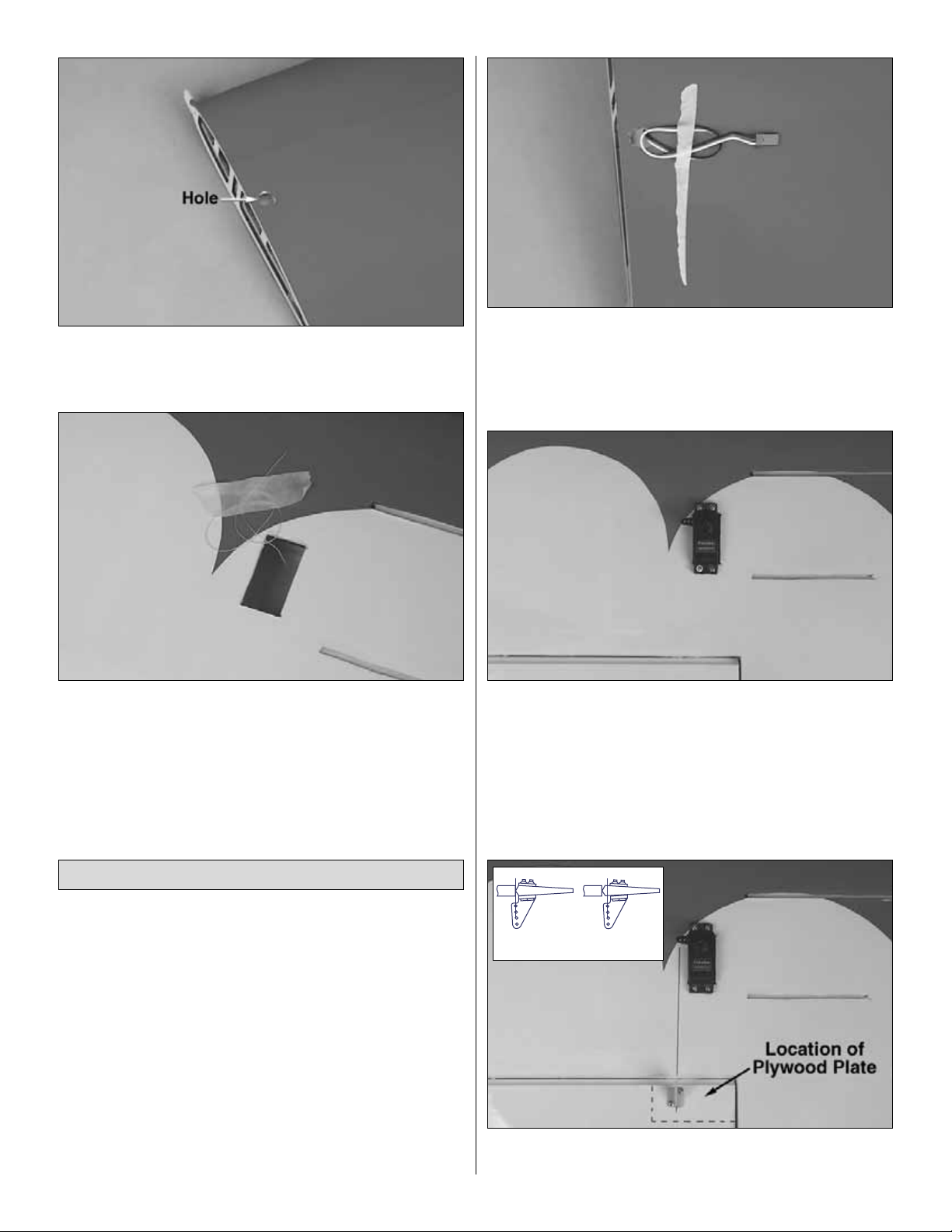
❏❏9. On the top of the wing, cut the covering away from
the hole at the wing center section. This hole is for the
aileron servo wire to come through, into the fuselage.
❏❏10.Remove the string from inside of the aileron servo
bay and tape it to the wing. Do not pull the string out of
the wing!
❏ 11. Repeat steps 1-10 for the left wing panel.
❏❏1. Installing the servos in the wing will require the use
of one 12" [305mm] servo extension for each aileron.One Yharness connector is required and is used to allow the
aileron servos to plug into one slot in your receiver.You may
have a computer radio that allo ws you to plug the servos into
separate slots and then mix them together through the radio
transmitter. If you choose to mix them with the radio rather
than the Y-harness, refer to the instructions with your
particular brand of radio.
❏❏2. Attach the ser vo extension to the aileron servo.
Secure the connectors together using a large piece of
heat shrink tubing, tape or other method for securing the
connectors together.
❏❏3.Tie the string from inside the wing to the end of the
servo wire. Pull the servo wire through the wing with the
string.Feed the servo wire out the hole in the top of the wing
center section. Tape the servo wire to the wing to prevent it
from falling back into the wing.
❏❏4.Temporarily position the aileron servo into the servo
bay. Drill a 1/16" [1.6mm] hole through the four mounting
holes of the servo, drilling through the plywood mounting plate
in the wing. Install and remove a servo mounting screw into
each of the four holes.Inser t a drop of thin CA into the holes
to harden the wood.After the glue has cured, install the servo
into the servo bay using the hardware that came with your
servo.Center the servo and install a ser vo arm as shown.
❏❏5. Position a large nylon control horn on the aileron,
positioning it as shown in the sketch and aligning it with the
Install the Aileron Servos and Pushrods
9
Correct Incorrect
Page 10
servo.Mark the location for the screw holes.Drill through the
marks you made with a 1/16" [1.6mm] drill bit. (Be sure you
are drilling into the plywood plate mounted in the bottom of
the aileron. Drill through the plate only. Do not drill all the
way through the aileron!) Using a #2 x 1/2" [#2 x 13mm]
sheet metal screw , install and then remo v e a scre w into each
of the holes.Harden the holes with thin CA.Install the control
horn with four #2 x 1/2" [#2 x 13mm] sheet metal screws.
❏❏6. Locate a .074" x 6" [.074" x 152mm] pushrod wire
threaded on one end. Screw a nylon clevis onto the threaded
end of the wire 20 turns. Install a silicone clevis keeper onto
the clevis.Then, install the clevis on the aileron control horn.
❏❏7. Be sure the aileron servo is centered. Enlarge the
first hole in the servo arm with a Hobbico Servo Horn Drill
(or a #48 or 5/64" [2mm] drill bit). Center the aileron and
align the wire pushrod with the hole in the end of the servo
arm.Using a marker, mark the location where the wire aligns
with the hole in the servo arm. On that mark make a 90
degree bend. From the bend measure an additional 3/16"
[4.8mm] and then cut off the excess pushrod wire.
❏❏8. Install the wire into the hole in the servo arm using
a nylon FasLink™as shown in the sketch.
❏ 9. Repeat steps 1-8 for the left wing panel.
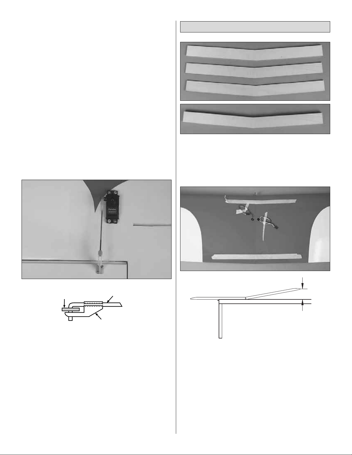
❏1.Locate the three hardwood wing joiners.Using 5-minute
epoxy, glue them together forming one 1/4" [6mm] wing joiner.
❏ 2. Test fit the wing joiner into each wing panel, making
sure that it is not too tight. Sand the joiner as needed to get
a good fit.
❏3.Apply 30-minute epoxy to both sides of the wing joiner , the
joiner pocket in both wing panels and to the root rib of each
wing panel. Push the wing panels together and hold them in
place with masking tape.Before the glue cures, set the wing flat
on your bench and measure the dihedral.The distance from the
top of the bench to the center of the wing as measured at the
wingtip should be approximately 6" [152mm].Block the wingtip
up while the glue cures.
Note: Due to production techniques
there may be some variance in the actual dihedral of each
model. Our prototypes flew well with the dihedral anywhere
between 5-3/4" and 6-1/4" [146mm and 159mm].
❏ 4. Set the wing aside allowing the glue to cure.
Join the Wings
FasLink
2-56 (.074") Pushrod Wire
Servo Horn
10
6"
Workbench
Page 11
❏ 5. Locate the 1/4" [6mm] holes under the covering at the
trailing edge of the wing center section. Cut the covering
away on both the top and bottom of the wing.
❏ 6.Trial fit the wing to the fuselage with two 1/4 - 20 nylon
wing bolts.After fitting the wing, remove it from the fuselage.
❏❏1. Locate the wire landing gear. Insert the r ight gear
into the slots in the bottom of the wing. When properly
inserted the landing gear has a forward rack.
❏❏2. Position four nylon landing gear straps over the
landing gear wire. Using the measurements shown in the
photo, mark the location for the screw holes.
Note: It is
important that the straps are located as shown or they could
interfere with the installation of the wheel pants.
Drill a 1/16"
[1.6mm] hole through the marks, drilling through the
hardwood rail under the covering.Inser t a #2 x 1/2" [13mm]
screw into each of the holes you have drilled and then
remove it.Put a couple of drops of thin CA into the holes to
harden the wood and allow the glue to cure. Install each of
the landing gear straps over the landing gear wire with #2 x
1/2" [13mm] sheet metal screws.
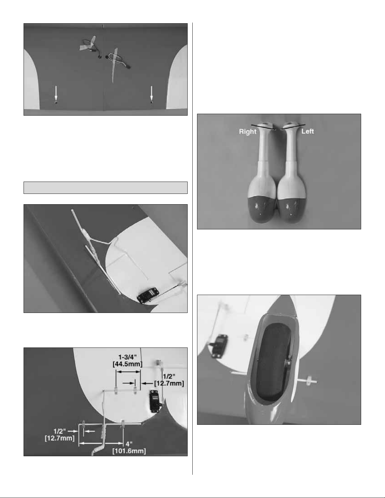
❏❏3. Locate the right side wheel pant.
Note: If you
examine the base of the two wheel pants you will see that
there is a definite difference in the angle of the base of the
wheel pant.This is to accommodate the dihedral in the wing.
Be sure you mount the correct pant to each side of the wing.
❏❏4. Slide the wheel pant over the landing gear wire.
Locate the axle, a 6-32 x 1/2" socket head cap screw and a
wheel. Insert the 6-32 socket head cap screw into the axle.
Slide the wheel over the axle.Temporarily tighten the axle to
the landing gear wire.Having the wheel in position will assist
you in locating the proper position for the wheel pant.
Install the Landing Gear
11
Page 12

❏❏5. Position the wheel pant so that the wheel is
centered in the opening. Mark four locations for the wheel
pant mounting screws onto the base of the wheel pant, two
on each side of the pant.The mounting hole locations
MUST
be over the hardwood rails that the landing gear straps are
screwed into. Once you are satisfied with the locations you
have marked, remov e the wheel and the wheel pant from the
landing gear wire.
❏❏6. Dr ill a 1/8" [3mm] hole though the wheel pant on
each of the four marks you have made.
❏❏7. Place the wheel and the wheel pant back onto the
landing gear wire. Position the wheel pant on the wing.
Using the holes in the wheel pant as your guide, drill a 5/64"
[2mm] hole through the hardwood rails in the wing. Remove
the wheel and wheel pant. Insert and then remove a #4 x
5/8" [15.9mm] sheet metal screw into each of the four holes
you have drilled in the wing.Put a couple of drops of thin CA
into the holes and allow the glue to cure.Once the glue has
cured install the wheel pant to the wing with four #4 x 3/8"
[9.5mm] sheet metal screws.
❏❏8.Locate two 1/8" x 3/8" x 3/8" [3mm x 51mm x 51mm]
plywood plates. From one edge of the plate measure in
7/8" [22.2mm] and mark a line onto the top edge and face of
each plate.
❏❏9. Place the wheel and axle onto the landing gear
wire. Position the plate so that the mark you have made on
the plate is in line with the axle. (The 7/8" [22.2mm] portion
of the plate should be to the rear of the wheel pant). Place
two reference marks on the edge of the wheel pant to help
align the plate in the following step. Do this for both plates
and both sides of each wheel pant.
❏❏10. Using 220-grit sandpaper, sand the inside of the
wheel pant in the area the plates will be glued to. After
12
Page 13

sanding, clean the area with rubbing alcohol. Mix 1/4 ounce
[2 drams] of 6-minute epoxy and some microballoon filler.
Add enough filler to make it difficult for the epoxy to run.
Glue the plates inside each of the wheel pants, referencing
the marks you made.You can hold the plates in place with
small clamps. You might find it easier to glue the plates in
one at a time rather than trying to do them together.
❏❏11. Install the wheel and axle onto the landing gear
wire. Tighten the axle set screw. This should leave a small
mark in the paint. Remove the wheel and axle. File a flat
spot on the mark so that the axle will not rotate on the
landing gear wire.
❏❏12. Permanently install the axle and wheel to the
landing gear wire.File a flat spot on the wire where the 5/32"
[4mm] wheel collar will be located. Install a 5-32" [4mm]
wheel collar onto the axle to lock the wheel to the axle.
❏ 13. Repeat steps 1-12 for the other landing gear and
wheel pant.
❏ 1. Locate the fiberglass belly pan. Mark the center of the
belly pan on the face of the belly pan.Cut a notch 5/16" x 5/16"
[7.9mm x 7.9mm] on the centerline.This will provide clearance
for the belly pan to fit over the leading edge of the wing. Trim
the sides of the belly pan on the “cut”lines.
❏ 2. Install the wing onto the fuselage. Place the belly pan
in position on the wing. Transfer the location for the wing
bolts to the belly pan.Cut 1/2" [13mm] clearance holes in the
belly pan for the head of the wing bolts.
❏ 3. Place the belly pan back onto the fuselage. Using a
fine line marker, draw the outline of the belly pan flanges
onto the bottom of the wing.
Install the Belly Pan
13
Page 14

❏ 4.1/16" [1.6mm] inside the lines you have drawn cut a 3/4"
[19mm] wide strip of covering from the wing.Use a sharp #11
hobby knife or use the Expert Tip that follows to cut the
covering from the wing along the lines you marked.Use care
to cut only into the covering and not into the wood.
How to cut covering from balsa.
Use a soldering iron to cut the covering from the stab.The
tip of the soldering iron doesn't have to be sharp, but a fine
tip does work best. Allow the iron to heat fully. Use a
straightedge to guide the soldering iron at a rate that will just
melt the covering and not burn into the wood.The hotter the
soldering iron, the faster it must trav el to melt a fine cut.Peel
off the covering (see the photo at step 4).
❏ 5.Where the belly pan contacts the wing, sand the inside
of the belly pan with 220-grit sandpaper and then wipe the
residue clean with rubbing alcohol. After the alcohol has
dried, glue the belly pan to the wing with 6-minute epoxy.You
will find it easier to glue one side at a time rather than trying
to do both sides together.
If you are using the O.S. .91 two-stroke engine you will
need to use a muffler extension (OSMG2582) to help
clear the bottom of the fuselage.
You now need to make a few decisions about the engine
installation. Provided on page 35 in this instruction manual
are two different engine mounting templates.One is for the
O.S. 1.20 four-stroke engine and the other is for the O.S.
.91 two-stroke engine. If you are using another brand of
engine or engine mount you will have to do some
measuring and use the reference marks in the fuselage to
center the mount for your engine.The large opening in the
bottom of the fuselage is to provide an easy exit for most
standard mufflers.The engine mounting templates position
the engines to allow the muffler on the O.S. 1.20 or the
O.S..91 to exit through this opening.
Install the Engine and Throttle Servo
ASSEMBLE THE FUSELAGE
14
Page 15

❏ 1. Locate the left and right halves of the engine mount.
Remove the molded spreaders, leaving the engine mount
to look like the photograph. Be sure the two halves fit
together smoothly.
The next few steps are going to cover installing the engine
onto the motor mount. You may have assembled other kits
where you installed the mount to the fuselage first. By
mounting the engine to the mount first you can easily
position the engine and muffler on the firewall as needed.
❏ 2. Position your engine onto the engine mount. Position
the engine on the mount so that the distance from the back
of the engine mount to the front of the engine thrust washer
is 6" [152mm].
❏ 3. Using the engine as a guide, locate the four holes for
the engine bolts. This is easily accomplished with a Great
Planes Dead Center Tool (GPMR8130). Drill four #29 or
9/64" [3.6mm] holes in the mount.Then, use an 8-32 tap to
thread the holes.
❏ 4. Use four 8-32 x 1" [8-32 x 25mm] socket head cap
screws, four #8 lock washers, four #8 flat washers and
Thread-Lock to install the engine onto the mount.
❏ 5. Locate the fiberglass fuselage. On the firewall you will
find reference marks for the engine mount.Using a felt tip pen,
draw over the reference marks and extend them further out
onto the fuselage.This will assist you in mounting the engine.
Even with the extension it will be necessary to make a small
clearance opening in the bottom of the fuselage to allow
clearance between the muffler and the fuselage.Depending
on the brand of engine used, you may have to change the
position of this clearance hole. Again, depending on the
engine you use you ma y or ma y not ha v e to cut the co wl f or
a standard muffler to clear.You may want to consider using
a “Pitts” style muffler.
As you can see there are some variables that y ou will hav e
to work with depending on the engine you choose. The
O.S. 1.20 four-stroke is our engine of choice because of
how neatly it fits inside of the cowl.Before proceeding with
installing the engine mount and engine, be sure you spend
some time looking closely at how your engine will fit into
the cowl and how well the muffler exits the fuselage.
15
Page 16

❏ 6. Tape the proper engine mount template to the firewall,
aligning the template on the lines you have drawn on the
firewall. Drill a 3/32" [2.4mm] pilot hole through each of the
marks in the corners of the template.Enlarge each of the holes
by drilling through the pilot holes with a 3/16" [4.8mm] drill bit.
❏ 7. Remove the template and install four 8-32 blind nuts
on the backside of the firewall. This is easily done if you
insert an 8-32 bolt into a #8 washer. Insert the bolt and
washer through the hole. Reach into the fuselage with the
blind nut, screwing it to the bolt.Tighten the bolt against the
firewall, pulling the blind nut into place.
❏ 8. Mount the engine mount and engine to the fuselage
with four 8-32 x 1" [8-32 x 25mm] socket head cap screws,
four #8 lock washers, four #8 flat washers and Thread-Lock.
(Depending on your engine, you may have to remove the
engine from the engine mount before installing the mount to
the firewall.If this is the case with your engine, re-install the
engine to the mount after the mount is attached to the
fuselage).
Leave the bolts slightly loose. Center the engine
on the firewall and then tighten the bolts.
❏ 9. Locate the die-cut 3mm plywood parts for constructing
the throttle servo tray. Glue them together as shown.
❏ 10. Drill four 1/16" [1.6mm] mounting holes in the servo
tray f or the throttle servo.Thread a mounting screw (included
with the servo) into each hole and then remove the screw.
Apply thin CA to the holes to harden the wood.After the glue
has cured, install the servo into the tray using the hardware
that came with the servos.
❏ 11. Drill a 1/8" [2.8mm] hole into the servo tray on each
side of the servo.
Note: The next 7 steps show how to install the throttle
servo for the O.S. 1.20 four-stroke and the O.S. .91 twostroke. As mentioned earlier you may have to modify
these steps for your particular engine. On some of our
prototypes we installed the throttle servo inside the
fuselage using the tray that is provided.Take a minute to
read through these steps before proceeding with the
installation of your throttle servo.
16
Page 17

❏ 12. Position the servo tray with the arm on the servo so
that it is in line with the carburetor arm.
❏ 13.On the firewall mark the location of the two holes you
drilled in the servo tray. Drill through the marks on the
firewall with a 1/8" [2.8mm] drill bit.
❏ 14.Install 4-40 blind nuts inside of the fuselage into the two
holes you drilled.
(Note: Because there are lightening holes in
the firewall former it is possible that you may only drill through
the fiberglass and not the plywood.If this is the case, drill a 1/8"
[2.8mm] hole through scrap plywood and insert the blind nut
into it.Then, place the plywood in position on the firewall. DO
NOT try to pull a blind nut through the fiberglass.)
Mount the
servo tray to the firewall with two 4-40 x 1/2" [4-40 x 13mm]
socket head cap screws and #4 washers.
❏ 15. Cut off the threaded portion of a 6" [13mm] wire
pushrod. Make a 90 degree bend on the end of the wire
leaving 3/16" [4.8mm] extending from the bend.Install a brass
quick connect onto the throttle arm using the nylon retainer.
Enlarge the first hole in the servo arm with a Hobbico Servo
Horn Drill (or a #48 or 5/64" [2mm] drill bit). Insert the straight
end of the wire into the hole in the brass quick connect.Insert
the opposite end through the hole in the servo arm. Install a
nylon Faslink onto the servo arm and then center the servo.
Center the throttle barrel and then tighten the 4-40 x 1/4"
[4-40 x 6mm] socket head cap screw onto the wire.
❏ 16. Cut a small opening in the firewall for the throttle
servo wire to pass into the fuselage. Be sure you position
the opening in a place that will not obstruct the installation of
the fuel tank.
❏ 1.Assemble the fuel tank as shown in the sketch.When
tightening the center screw be sure not to over tighten it.You
just want it snug enough to pull the rubber stopper tight
against the tank.
Install the Fuel Tank
FasLink
2-56 (.074") Pushrod Wire
Servo Horn
RETAINER
17
Fuel T ank
Top of Fuselage
Silicone Fuel Line
Fuel Clunk
Fuel Pipe
Pressure T ap
to Muffler
To Needle
Valve
Firewall
Page 18

❏ 2. Install the tank into the fuselage with the neck of the
tank through the firewall. Hold the tank in place inside the
fuselage by wrapping two #64 rubber bands around the
tank, attaching the bands to the tabs in the plywood former
that supports the tank.
❏3. Install silicone fuel tubing (not included in the kit) onto the
aluminum tubes from the fuel tank.The line with the fuel clunk
will feed to the fuel inlet at the needle valve and the other will
attach to the pressure tap on the muffler.For our installation we
chose to use an external fill valve. If you choose to do this as
well, follow the instructions with your particular brand of fuel
valve. Should you choose not to install a fuel filler valve you
can fill the fuel tank by removing the fuel line to the carburetor
and filling through it. However, depending how you cut out the
cowling to accommodate the engine, the cowling may make it
difficult to access the carburetor .Y ou can also install a third line
to the tank and use it for filling the tank.The method you use
is your choice but make your decision before moving onto the
installation of the fuel tank.
You may already have discovered that the Gee Bee stands
on its tail pretty well. For the installation of the cowl you
will find it helpful to stand the fuselage on its tail.
Temporarily slide the stab into place in the fuselage. This
will aid standing it on the tail.Placing a couple of chairs on
each side of it will prevent it from accidentally falling o ver!
❏ 1. Locate two 1/8" [3mm] plywood cowl rings and four
1/8" [3mm] plywood mounting tabs.
❏ 2. Measure up from the bottom of the tab 3/4" [19mm]
and draw a line across it.
❏ 3. Stand the fuselage on its tail. Place one of the cowl
rings on the firewall with the tabs of the ring placed as
shown in the picture (this placement is not critical). Make
sure the cowl ring is centered and is an equal distance from
the sides of the fuselage.
❏ 4. Using the cowl ring as your reference, mark the locations
for the plywood mounting tabs with a fine tip felt marker.
❏ 5.Roughen the area you marked on the firewall with 220-
grit sandpaper.Then wipe the area clean with rubbing alcohol.
Install the Cowl Ring, Cowl
and Dummy Engine
18
Page 19

Glue the tabs to the firewall with 5-minute epo xy.Align the line
on each tab with the edge of the firewall. After the glue has
cured drill two 1/16" [1.6mm] holes in each tab and through
the firewall.Screw a #2 x 1/2" [#2 x 13mm] sheet metal screw
into each of the holes drilled in the tabs.Note: When installing
the screws, be sure to tighten the outermost screws until they
compress into the wood so they are flush with the surface of
the tab.This is necessary so when you mount the cowl ring to
the tabs the ring sits flat on the mounting tabs.
❏ 6. Glue the two cowl rings together forming one 1/4"
[6mm] thick cowl ring.
❏ 7. Use small clamps to hold the cowl ring in position on
the tabs. Adjust the ring until the distance from the outer
edge of the fuselage to the inside edge of the cowl ring is the
same all the way around the cowl ring. Number each finger
of the cowl ring and number the corresponding mounting
tab. You will find this helpful later when matching the cowl
ring and the tabs when installing the cowl.
❏ 8. With the cowl ring still being held in place with the
clamps, on one tab measure 1/2" [13mm] from the outer edge
of the cowl ring towards the fuselage. Make this mark in the
center of the tab. On the mark, drill through the ring and the
mounting tab with a 1/16" [1.6mm] drill bit. Remove the clamp
and screw a #2 x 1/2" sheet metal screw through the cowl ring
and into the mounting tab.Repeat this for all four tabs.
❏ 9. Remove one of the screws from one tab. Drill a 1/8"
[3mm] hole through the hole the screw was in on both the
cowl ring and the tab. Now drill a 5/32" [4mm] hole through
the cowl ring and the tab (
drilling through the holes with a
progressively larger bit prevents the plywood from splitting
).
Insert a 6-32 blind nut into the cowl ring.Use a small amount
of epoxy to glue the blind nut to the cowl ring.
❏ 10. Install a 6-32 x 1/2" [6-32 x 13mm] socket head cap
screw and a #6 washer through the back side of the
mounting tab and into the blind nut in the cowl ring.Tighten
the screw to the blind nut.
❏11. Remove a screw from another tab and repeat the same
procedure of installing a bolt, washer and blind nut.Do this to
all four mounting tabs, mounting the ring to the fuselage.
19
Page 20

❏ 12. Cut a hole in the center of the dummy engine large
enough to clear the thrust washer of the engine.Position the
dummy engine over the engine. For proper positioning the
oil sump should be at the bottom of the fuselage and the top
cylinder should be at the top-center of the fuselage. Mark
the area where the dummy engine covers the engine’s
cylinder head. Cut this part of the dummy engine away.
❏ 13. Drill 1/8" [3mm] holes into the bottom-center of each
rocker cov er and on the marks on the case of the dummy engine.
❏ 14. Insert a 1/8" x 3" [3mm x 76mm] aluminum tube in
each of the holes you drilled. Make sure that each fits well,
and then remove the tubes from the engine.
❏ 15.Paint the dummy engine with a fuel proof paint. Paint
the cylinders and the area around them flat black and the
engine case a light gray. After the paint is dry insert the
aluminum tubes into the dummy engine.Hold them in place
by applying a small amount of epoxy to each tube on the
back side of the dummy engine. You can add additional
detail to the dummy engine by drilling a small hole in each
cylinder to accept the spark plug wires. Use small gauge
wire (not included) for the spark plug wires.
❏ 16. Measure into the cowl from the trailing edge of the
cowling 2" [50mm] and make a few reference marks. Using
220-grit sandpaper, sand the entire inside of the cowl in the
area that you have made the marks.This is the area the cowl
ring will contact the cowl.Sand the front 1-1/2" [38mm] of the
inside of the cowl to prepare it for the dummy engine. Wipe
the areas you've sanded with rubbing alcohol to clean away
the residue.
20
Page 21

❏ 17. Place the cowl onto the ring, center ing the cowl on
the engine. Do not push the cowl onto the cowl mounting
ring too hard as this could deform the shape of the cowl.
❏ 18. Reaching carefully into the inside of the cowl, tack
glue the cowl to the cowl mounting ring with medium CA.Be
sure you do not move the cowl while reaching inside. Spray
the glue with accelerator to make sure the glue is fully cured.
❏ 19. Once the glue is fully cured, remove the cowl and the
cowl mounting ring from the fuselage by removing the four
socket head cap screws that hold the cowl to the fuselage.
Apply a small bead of medium CA to firmly attach the cowl
mounting ring to the cowl. Allow the CA to fully cure.
❏ 20. Mix 1/4 ounce of 6-minute epoxy with microballoon
filler.Apply a fillet of the epoxy to the cowl mounting ring and
the cowl. The fillet should be made on the front of the cowl
mounting ring. Applying the epoxy to the back of the ring
could interfere with the cowl mounting tabs.
❏ 21. Now is a good time to make any cut-outs in the cowl
for things such as a needle valv e e xtension, choke e xtension
or a remote glow adapter. If you are using a long-necked
Nicd glow driver there is no need for a remote glow plug
adapter.For our installation we chose to use a Sullivan Head
Lock Remote (MODP1221). Re-install the cowl onto the
fuselage.This will allow you to look into the front of the cowl
to determine exactly where any holes may ha ve to be drilled.
When you have finished, remove the cowl.
❏ 22.With the fuselage standing on its tail, place the dummy
engine over the engine.Then place the cowl over the dumm y
engine. Attach the cowl to the fuselage with the four socket
head cap screws. To position the dummy engine you will
need two 9" [229mm] balsa sticks and two small rubber
bands (not included). Loop a rubber band through a couple
of the aluminum tubes on one side of engine crankshaft.
Insert the stick through the rubber bands and place the stick
onto the front of the cowl.This will pull the dummy engine into
the front of the cowl. Repeat this with the second stick and
rubber band on the other side of the engine crankshaft.
❏23.Position the dummy engine so that the cut out is ov er the
engine cylinder and the hole you cut in the center of the dummy
engine is centered on the engine thrust washer. Be sure the
center cylinder on the dummy engine is centered at the top of
the fuselage and the oil sump is centered on the bottom of the
fuselage. When you are satisfied with the positioning of the
dummy engine, carefully remove the cowl from the fuselage
being careful not to disturb the dummy engine.
❏ 24. Tack-glue the dummy engine to the cowl from inside
the cowl.Re-install the cowl to the fuselage to verify that the
dummy engine is placed properly. When you are satisfied
with the way it fits, remove the cowl from the fuselage and
permanently glue the dummy engine to the cowl from inside
the cowl with 6-minute epoxy mixed with microballoon filler.
21
Page 22

❏ 1.Temporarily install the wing onto the fuselage with two
1/4-20 nylon wing bolts.
❏ 2.T rial fit the horizontal stabilizer into the stabilizer saddle
at the rear of the fuselage.You may find it necessary to sand
inside the stabilizer saddle to remove any excess fiberglass
resin that may have accumulated in the molding process.
❏ 3. Once you are satisfied with the fit of the stabilizer
remove it from the fuselage.Using 220-grit sandpaper, lightly
sand the inside of the stabilizer saddle and the immediate
area inside the fuselage surrounding it. After you have
sanded the area, wipe the area clean with rubbing alcohol.
❏ 4. Re-install the stabilizer into the stabilizer saddle in the
fuselage. Center the stabilizer in the fuselage as shown in
the above sketch.
❏ 5. Once you have the stabilizer properly centered, use a
fine line felt tip pen to mark where the stab contacts the
fuselage. Mar k both the top and bottom of the stabilizer.
❏ 6. Remove the stab from the fuselage. Use the same
technique used for cutting the covering from the wing to
remove the cov ering from the top and bottom of the stab .Use
care to cut only into the covering and not into the wood.
❏ 7. Using 6-minute epoxy , glue the stab to the stab saddle .
Double check the alignment of the stab to the wing before
the glue cures. You can clean any excess epoxy from the
fuselage and stab with rubbing alcohol anytime before the
glue cures. Note: Do not be too concer ned about getting a
large amount of epoxy between the stab and the stab
saddle.Just get enough glue into the joint to hold it in place.
In the next step you will remove the wing and a solid glue
joint will be made inside of the fuselage.
❏ 8. Remove the wing from the fuselage. Mix a small
amount of 6-minute epoxy.Using a small stick, reach into the
fuselage and force the epoxy into the stab saddle and stab
to create a solid bond of the stab to the fuselage.You may
find it helpful to add a small amount of microballoon filler to
the glue.This will thicken the glue slightly preventing it from
running out of the joint too easily. Allow the glue to cure
before starting the next step.
❏ 9.On the end of the fuselage at the tailpost, measure up
from the bottom of the fuselage 1/8" [3mm] and make a line.
Measure up from this mark 7/8" [22mm] and make another
line. Between these two marks draw the centerline of the
fuselage. On the centerline, between the two lines you have
drawn, cut a 1/16" [1.6mm] slot.You will find that this is most
easily accomplished with the use of a high speed rotary tool
and a fiberglass cut-off wheel.
Mount the Stab, Elevator,
Rudder and Tailwheel
22
A
A
BB
B = BA = A
Page 23

❏ 10. Locate the tailwheel assembly. Trial fit the nylon
bearing into the slot you have cut.Adjust the slot as needed
until the nylon bearing fits into the slot.
❏ 11. Apply a small amount of petroleum jelly to the ends
of the nylon bearing to prevent glue from getting into the
nylon bearing and the tailwheel wire.Glue the nylon bearing
into the slot in the fuselage with 6-minute epoxy.
❏12. On the leading edge of the rudder measure up from the
bottom of the rudder 1" [25mm] and make a mark. On this
mark drill a 7/64" [2.8mm] hole into the leading edge of the
rudder.Make a 1/8" [3mm] slot 1/8" [3mm] deep in the leading
edge of the rudder from this hole to the bottom of the rudder.
❏ 13. Trial fit the rudder by sliding the rudder onto the
tailwheel wire.The nylon bearing should fit into the slot you
have cut in the rudder. Adjust the slot as needed until the
leading edge of the rudder is in contact with the trailing edge
of the fuselage. Remove the rudder and put a couple of
drops of thin CA into the hole to harden the wood. After the
glue has cured re-insert the rudder onto the tailwheel wire to
be sure everything still fits well.
❏ 14. Install three CA hinges using the same method as
used for the ailerons.Mix a small amount of 6-minute epoxy.
Work some epoxy into the hole you drilled in the rudder .Slide
the rudder onto the tailwheel wire and the hinges.When you
are satisfied with the fit apply 6 drops of CA glue to each
hinge. Be careful not to let the glue r un onto the fuselage.
❏ 15. Install a 4-40 set screw into each of the two 1/8"
[3mm] wheel collars. Slide a wheel collar onto the tailwheel
wire, then the tailwheel followed by another wheel collar.
Tighten the set screws in the wheel collars, centering the
tailwheel between them. Filing flat spots on the wire where
the wheel collars contact the wire will make a more secure
installation for the wheel collars.
❏ 16.Locate the left and right elevator halves. On one side
of each elevator you can see the outline of a hardwood plate
23
Page 24

under the covering. Use a pin to determine that you have
located the hardwood plate.Important! This is the bottom of
the elevator. The control horns mount to these plates and
when installed properly the plates are on the bottom of the
elevator. Determine which elevator is for the right side and
left side and then install them to the horizontal stab with three
hinges on each elevator. Use the same installation procedure
used for the ailerons and rudder.
❏ 1. Locate the 1/8" [3mm] plywood servo tray components.
Glue them together as shown to form two servo trays.
❏ 2. Locate the 1/8" [3mm] plywood battery/receiver tray
and two formers. Glue the tray together as shown.
❏ 3. Place one servo tray between the plywood formers
inside of the fuselage. Measure down from the wing saddle
to the top of the box 1-1/2" [38mm]. Make a reference mark
for positioning the servo tray when gluing it in place. Glue
the servo tray to the plywood formers and the fuselage.
❏ 4. Position the battery/receiver tray inside the fuselage as
shown. Make reference marks inside the fuselage identifying
where the formers contact the fuselage.Sand the areas where
the formers will contact the fuselage with 220-grit sandpaper.
Then wipe the area clean with rubbing alcohol.Glue the tray to
the fuselage with a mixture of 6-minute epoxy and
microballoon filler.Use a liberal amount of the mixture creating
a fillet of the mixture between the formers and the fuselage.
❏ 5. Install three servos, positioning them as shown. Dr ill
1/16" [1.6mm] holes for each servo screw. Install the screw
into the servo tray and then remove the screw. Apply a
couple of drops of thin CA to harden the wood.After the glue
has cured, install the servos with the hardware provided.
Install the Elevator and Rudder Servos,
Radio System and Pushrods
24
Page 25

❏ 6. On the left side of the fuselage below the stab are
located two molded pushrod exit locations.Cut them out. On
the right side of the fuselage is located one molded pushrod
exit. Cut it out as well.
❏❏7.Locate three .074 x 17-1/2" [444mm] wires threaded
on one end.From one wire cut a 6-1/2" [165mm] rod with the
threads at one end.
❏❏8.Locate three 1/4" x 16" [6mm x 406mm] wood dowels.
On one dowel measure from one end 1" [25mm] and make a
mark. On the mark, drill a 5/64" [2mm] hole through the dowel.
❏❏9. From the end of the dowel to the hole make a
groove the same width as the pushrod wire.
❏❏10.On the non-threaded end of the 6-1/2" [165mm] wire
make a 90 degree bend 1/4" [6mm] from the end of the wire.
❏❏11. Insert the wire into the hole in the dowel.Glue the
wire to the groove with a small amount of medium CA.
❏❏12. Locate one of the 2-3/8" [60mm] long pieces of
heat shrink tubing. Cut it in half. Slide one piece over the
wire and the dowel. Then shrink the tubing tightly to the
dowel and wire. The tubing can be shrunk with either a
modeling heat gun or a match.
❏❏13. From the leftover .074 x 17-1/2" [444mm] wire cut
a 7-1/2" [190mm] long, non-threaded wire.Make a 90 degree
bend 1/4" [6mm] from the end of the wire.
❏❏14. On the opposite end of the dowel measure in 1"
[25mm] and make a mark. On the mark, drill a 5/64" [2mm]
hole through the dowel.
❏❏15.From the end of the dowel to the hole mak e a groov e.
❏❏16. Insert the wire into the hole in the dowel.Glue the
wire to the groove with a small amount of medium CA.
❏❏17. Slide the remaining half of the heat shrink tubing
over the wire and dowel. Shrink the tubing tightly to the
dowel and wire.
2525
Page 26

❏18.Repeat steps 7 - 17 to make a second, matching pushrod.
❏❏19. Install a clevis and silicone clevis keeper to the
threaded end of the wire the same as was done with the ailerons.
❏❏20. Insert the end of the pushrod wire with the clevis
into the fuselage and out through the most forward of the
two pushrod exit holes.
❏❏21. Install a control horn onto the bottom of the
elevator with two #2 x 1/2" [13mm] sheet metal screws
following the same procedure used for the ailerons. Be sure
the control horn is aligned with the pushrod and is on the
hardwood plate in the bottom of the elevator.
❏ 22. Repeat steps 19 - 21 for the opposite elevator.
❏ 23. Center both elevators and the elevator servos. The
elevator servos are located in the lower servo bays on both
sides of the fuselage. Attach the pushrods to the elevator
servos using nylon Faslinks following the same procedure
used for the ailerons.
❏ 24. From the remaining .074 x 17-1/2" [444mm] wire cut
a 6-1/2" [165mm] long rod threaded on one end.
❏ 25. On the remaining dowel measure up 1" [25mm] at
both ends of the dowel and make a mark.On the mark, dr ill
a 5/64" [2mm] hole through the dowel on both ends.
❏ 26.From the ends of the dowel to the holes make g roov es.
❏ 27. On the non-threaded end of the 6-1/2" [165mm] wire
make a 90 degree bend 1/4" [6mm] from the end of the wire.
❏ 28. Inser t the wire into the hole in the dowel. Glue the
wire to the groove with a small amount of medium CA.
❏ 29. Locate the remaining 2-3/8" [60mm] long pieces of heat
shrink tubing. Cut it in half. Slide one piece over the wire and
the dowel and shrink the tubing tightly to the dowel and wire.
❏ 30. From the leftover .074 x 17-1/2" [444mm] wire cut an
8" [203mm] long wire. Make a 90 degree bend 1/4" [6mm]
from the end of the wire. Insert the wire into the hole in the
dowel. Glue the wire to the groove with a small amount of
medium CA. After the glue has cured, insert and heat the
final piece of heat shrink tubing to the end of the dowel.
❏31.Install a clevis and silicone clevis keeper to the threaded
end of the wire the same as was done with the elevators.
❏ 32.Inser t the end of the pushrod wire with the clevis into
the fuselage and out through the remaining pushrod exit
hole on the left side of the fuselage.
❏ 33. Install a control hor n onto the left side of the rudder.
When placing the control horn it must be aligned with the
rudder pushrod wire and be aligned with the plywood plate
located under the fiberglass skin of the rudder. If you press
lightly on the fiberglass on the left side of the rudder you can
feel where the plate is because the fiberglass will be
noticeably stiffer in that area.When placing the control hor n
it will have to be set back from the leading edge of the
rudder 1/8" [3mm]. When satisfied with the placement mar k
the mounting hole locations for the control horn.Drill a 1/16"
[1.6mm] hole through both marks. Insert and then remove a
#2 x 1/2" [13mm] sheet metal screw through each hole.
Apply a couple of small drops of thin CA into the holes.After
the glue has cured install a large nylon control horn to the
rudder with the two #2 sheet metal screws.
26
Page 27

❏ 34. Center the r udder and the rudder servo. Attach the
pushrod to the rudder servo using nylon Faslinks following
the same procedure used for the elevator. The final servo
installation should look as shown above.
❏35. Locate two 1/4" x 1/4" x 24" [6mm x 6mm x 610mm] wood
sticks. Cut one stick into two 10-3/4" lengths. Roughen, then
wipe the area of the fuselage where the stick will be glued with
rubbing alcohol. Glue the sticks into the fuselage above and
below the pushrods to support them. From the remaining stick
cut small pieces and glue them to the wood sticks to support the
sides of the pushrods. Be sure there is no binding of the
pushrods when you have finished gluing the sticks in place.
❏ 36.Wrap the battery pack and receiver in at least 1/4" of
R/C foam rubber and install them in the fuselage. On our
model the battery and receiver were mounted where shown
in the photo to minimize the amount of nose weight required
to balance the model at the correct C.G. Securely hold the
battery pack and receiver in position with #64 rubber bands
on the battery/receiver tray in the top of the fuselage.
❏ 37.Connect a Y-harness to the aileron servo wires in the
wing. Secure the connections with heat shr ink tubing, tape
or clips intended for that purpose. Install a 12" aileron
extension to the receiver for the ailerons.
❏ 38. Mount the receiver on/off switch. A Great Planes
Switch & Charge Jack Mounting Set (GPMM1000, not
included) was used on this model. Be certain it is in a
location away from engine exhaust.
❏ 39. Make cer tain all the servo arms are secured to the
servos with the screws that came with them and that all the
clevises have retainers on them.
❏ 40. Extend the receiver antenna, guiding it out of the
fuselage and connecting it to the tailwheel. Be certain there
is a strain relief inside the fuselage on the antenna to keep
stress off the solder joint inside the receiver. On our
prototype we drilled a 7/32" [5.6mm] hole through the
bottom of the fuse, installed a 1" [25mm] length of fuel tubing
into the hole and routed the antenna through the tubing. A
strain relief as shown in the sketch was used inside the
fuselage and the end of the antenna was connected to a
small rubber band that wraps around the tailwheel.
27
Page 28

❏ 1.Paint the pilot and install it in the cockpit area.
❏ 2.Trim, then glue the canopy in place.You can use either
aliphatic glue or if done carefully you can use 6-minute epoxy
as we did on our prototype.
❏ 3. Use scissors or a shar p hobby knife to cut the decals
from the sheet.
❏ 4. These photos will help you in placing the decals. On
the decal sheet there are sections of red and black material
that can be used to fill the gap on the numbers between the
wing and the aileron. Note: The bottom of the wing has the
same decals as the top but the N-number is on the left side
and the number “7” is on the r ight.
❏ 5. Be certain the model is clean and free from oily
fingerprints and dust. Prepare a dishpan or small bucket with
a mixture of liquid dish soap and warm water–about one
teaspoon of soap per gallon of water.Submerse the decal in
the soap and water and peel off the paper backing. Note:
Even though the decals hav e a “sticky-back” and are not the
water transfer type , submersing them in soap & water allo ws
accurate positioning and reduces air bubbles underneath.
❏ 6. Position decal on the model where desired. Holding the
decal down, use a paper towel to wipe most of the water a way.
❏ 7. Use a piece of soft balsa or something similar to
squeegee remaining water from under the decal. Apply the
rest of the decals the same way.
❏ 1. Turn on the transmitter and receiver and center the
trims. If necessary, remove the servo arms from the servos
and reposition them so they are centered. Reinstall the
screws that hold on the servo arms.
❏ 2. With the transmitter and receiver still on, check all the
control surfaces to see if they are centered.If necessary, adjust
the clevises on the pushrods to center the control surfaces.
IMPOR
TANT NOTE ABOUT SETTING UP THE ELEVATOR.
In our testing we have designed all of this airplane’s
incidences so that when the elevator is neutral it should be in
line with the horizontal stab.Be sure the elevator is positioned
as shown. If your plane is properly balanced as explained
later in this manual, the elevator should be fair ly close to the
neutral trim setting.
Check the Control Directions
GET THE MODEL READY TO FLY
Finishing T ouches
28
Page 29

❏ 3. Make certain that the control surfaces and the
carburetor respond in the correct direction as shown in the
diagram.If any of the controls respond in the wrong direction,
use the servo reversing in the transmitter to reverse the
servos connected to those controls. Be cer tain the control
surfaces have remained centered. Adjust if necessary.
Use a Great Planes AccuThrow (or a ruler) to accurately
measure and set the control throw of each control surface
as indicated in the chart that follows. NOTE: The throws
are measured at the widest part of the elevators, rudder
and ailerons.
At this stage the model should be in ready-to-fly condition
with all of the systems in place including the engine, landing
gear, covering and paint and the radio system.
❏ 1. Use a felt-tip pen or 1/8"-wide tape to accurately mark
the C.G.on the top of the wing on both sides of the fuselage.
The C.G. is located 2-3/4" [70mm] back from the leading
edge of the wing.
❏ 2.With the wing attached to the fuselage, all parts of the
model installed (ready to fly) and an empty fuel tank, place
the model upside-down on a Great Planes CG Machine. If
you are using the C.G Machine you will have to use longer
rods for the base of the machine due to the width of the
fuselage. If you do not wish to do this you can remove the
balancing rods, place the pads on the C.G. location and lift
the model while holding onto the rods.
This is where your model should balance.For the Gee Bee
we do not recommend
that you move the C.G.forward or
back from this point. In our testing we found that moving
the C.G. too far aft causes the plane to snap with the
recommended elevator control throw. Moving the C.G
forward did not add to the overall stability of the plane and
only caused the plane difficulties while flaring for landing.
More than any other factor, the C.G. (balance point) can
have the greatest effect on how a model flies and may
determine whether or not your first flight will be successful.
If you value this model and wish to enjo y it for many flights,
DO NOT OVERLOOK THIS IMPORTANT PROCEDURE.
A model that is not properly balanced will be unstable and
possibly unflyable.
Balance the Model (C.G.)
These are the recommended control surface throws:
ELEVATOR: 5/8" [15.9mm] up
5/8" [15.9mm] down
RUDDER: 1" [25mm] right
1" [25mm] left
AILERONS: 7/8" [22.2mm] up
7/8" [22.2mm] down
IMPORTANT: The Gee Bee has been extensively flown
and tested to arrive at these throws.We have tested a r ange
of control throws and have f ound that
you must
set them as
listed above.With these throws the model performs very well
and will not snap or roll violently. Coupled with these throws,
your properly balanced model will perform very well.
Set the Control Throws
4-CHANNEL RADIO SETUP
29
(STANDARD MODE 2)
4-CHANNEL
TRANSMITTER
ELEVATOR MOVES UP
4-CHANNEL
TRANSMITTER
RUDDER MOVES RIGHT
4-CHANNEL
TRANSMITTER
RIGHT AILERON MOVES UP
LEFT AILERON MOVES DOWN
CARBURETOR WIDE OPEN
4-CHANNEL
TRANSMITTER
2-3/4"
[70mm]
Page 30

If you do not have a C.G. machine we recommend that you
balance the plane as shown here. Mark the location for the
C.G. on the wing, close to the wing saddle. Remove the
wing, and then wrap a lightweight cord or wire around the
fuselage. Put the wing back onto the fuselage. Suspend the
airplane from the cord, making sure the cord is on the marks
you have made.
❏ 3. If the tail drops, the model is “tail heavy”and the battery
pack and/or receiver must be shifted forward or weight must
be added to the nose to balance.If the nose drops, the model
is “nose heavy”and the battery pack and/or receiver must be
shifted aft or weight must be added to the tail to balance. If
possible, relocate the battery pack and receiver to minimize
or eliminate any additional ballast required. If additional
weight is required, nose weight may be easily added b y using
a “spinner weight” (GPMQ4645 for the 1 oz. weight, or
GPMQ4646 for the 2 oz. weight). If spinner weight is not
practical or is not enough, use Great Planes (GPMQ4485)
“stick on”lead.A good place to add stick-on nose weight is to
the firewall (don't attach weight to the cowl–it is not intended
to support weight). Begin by placing incrementally increasing
amounts of weight on the fuse over the firewall until the
model balances. Once you have determined the amount of
weight required, it can be permanently attached.
Note: Do not rely upon the adhesive on the back of the lead
weight to permanently hold it in place. Over time, fuel and
exhaust residue may soften the adhesive and cause the
weight to fall off .Use #2 sheet metal screws, RTV silicone or
epoxy to permanently hold the weight in place.
❏ 4. IMPORTANT: If you found it necessary to add any
weight, recheck the C.G.after the weight has been installed.
❏ 1. With the wing level, have an assistant help you lift the
model by the engine propeller shaft and the bottom of the
fuse under the TE of the fin.Do this several times.
❏2.If one wing always drops when you lift the model, it means
that side is heavy. Balance the airplane by adding weight to the
other wing tip. An airplane that has been laterally balanced
will track better in loops and other maneuvers.
No matter if you fly at an AMA sanctioned R/C club site or if you
fly somewhere on your own, you should always have your
name, address, telephone number and AMA number on or
inside your model.It is required at all AMA R/C club flying sites
and AMA sanctioned flying events. Fill out the identification tag
on the decal sheet and place it on or inside your model.
Follow the battery charging instructions that came with your
radio control system to charge the batteries. You should
always charge your transmitter and receiver batteries the
night before you go flying and at other times as
recommended by the radio manufacturer.
NOTE: Checking the condition of your receiver battery pack
is highly recommended. All battery packs, whether it's a
trusty pack you've just taken out of another model, or a new
battery pack you just purchased, should be cycled, noting
the discharge capacity. Oftentimes, a weak battery pack can
be identified (and a valuable model saved!) by comparing its
actual capacity to its rated capacity. Refer to the instructions
and recommendations that come with your cycler. If you
don't own a battery cycler, perhaps you can have a friend
cycle your pack and note the capacity for you.
Charge the Batteries
Identify Y our Model
PREFLIGHT
Balance the Model Laterally
IMPORTANT! DO NOT BALANCE THE AIRPLANE
WITH YOUR FINGERS!
The C.G. range is critical and there is not a lot of margin
for moving the C.G. forward or aft of the recommended
location. Balancing with your fingers is not accurate
enough for balancing this model.
30
Page 31

Carefully balance your propeller and spare propellers before
you fly. An unbalanced prop can be the single most significant
cause of vibration that can damage your model. Not only will
engine mounting screws and bolts loosen, possibly with
disastrous effect, but vibration may also damage your radio
receiver and battery. Vibration can also cause your fuel to
foam, which will, in turn, cause your engine to run hot or quit.
We use a Top Flite Precision Magnetic Prop Balancer
™
(TOPQ5700) in the workshop and keep a Great Planes
Fingertip Prop Balancer (GPMQ5000) in our flight box.
If the engine is new, follow the engine manufacturer's
instructions to break-in the engine. After break-in,
confirm that the engine idles reliably, transitions smoothly
and rapidly to full power and maintains full powerindefinitely. After you run the engine on the model, inspect
the model closely to make sure all screws remained tight,
the hinges are secure, the prop is secure and all pushrods
and connectors are secure.
Ground check the operational range of your r adio before the
first flight of the day. With the transmitter antenna collapsed
and the receiver and transmitter on, you should be able to
walk at least 100 feet away from the model and still have
control. Have an assistant stand by your model and, while
you work the controls, tell you what the control surfaces are
doing. Repeat this test with the engine running at various
speeds with an assistant holding the model, using hand
signals to show you what is happening. If the control
surfaces do not respond correctly, do not fly! Find and
correct the problem first.Look for loose servo connections or
broken wires, corroded wires on old servo connectors, poor
solder joints in your battery pack or a defective cell, or a
damaged receiver crystal from a previous crash.
Keep all engine fuel in a safe place, away from high heat,
sparks or flames, as fuel is very flammable. Do not smoke
near the engine or fuel; and remember that engine exhaust
gives off a great deal of deadly carbon monoxide.Therefore
do not run the engine in a closed room or garage.
Get help from an experienced pilot when learning to
operate engines.
Use safety glasses when starting or running engines.
Do not run the engine in an area of loose gravel or sand;the
propeller may throw such material in your face or eyes.
Keep your f ace and body as well as all spectators a wa y from the
plane of rotation of the propeller as you start and run the engine.
Keep these items away from the prop: loose clothing, shirt
sleeves , ties, scarfs, long hair or loose objects such as pencils
or screwdrivers that may fall out of shirt or jacket pockets into
the prop.
Use a “chicken stick” or electric starter to star t the engine.
Do not use your fingers to flip the propeller .Make certain the
glow plug clip or connector is secure so that it will not pop
off or otherwise get into the running propeller.
Make all engine adjustments from behind the rotating propeller .
The engine gets hot! Do not touch it during or right after
operation. Make sure fuel lines are in good condition so fuel
will not leak onto a hot engine, causing a fire.
To stop a glow engine, cut off the fuel supply by closing off
the fuel line or following the engine manufacturer's
recommendations. Do not use hands, fingers or any other
body part to tr y to stop the engine. Do not throw anything
into the propeller of a running engine.
Read and abide by the following Academy of Model
Aeronautics Official Safety Code:
1. I will not fly my model aircraft in sanctioned events, air
shows, or model flying demonstrations until it has been
proven to be airworthy by having been previously
successfully flight tested.
General
AMA SAFETY CODE (
EXCERPT
)
Failure to follow these safety precautions may result
in severe injury to yourself and others.
ENGINE SAFETY PRECAUTIONS
Range Check
Ground Check
Balance Propellers
31
Page 32

2. I will not fly my model aircraft higher than approximately
400 feet within 3 miles of an airport without notifying the
airpor t operator. I will give right of way to and avoid flying in
the proximity of full scale aircraft. Where necessary an
observer shall be used to supervise flying to avoid having
models fly in the proximity of full scale aircraft.
3. Where established, I will abide by the safety rules for the
flying site I use and I will not willfully and deliberately fly my
models in a careless, reckless and/or dangerous manner.
7. I will not fly my model unless it is identified with my name
and address or AMA number, on or in the model.
9. I will not operate models with pyrotechnics (any device
that explodes, burns, or propels a projectile of any kind).
1.I will have completed a successful radio equipment ground
check before the first flight of a new or repaired model.
2. I will not fly my model aircraft in the presence of
spectators until I become a qualified flier, unless assisted b y
an experienced helper.
3. I will perform my initial tur n after takeoff away from the pit
or spectator areas and I will not thereafter fly over pit or
spectator areas, unless beyond my control.
4. I will operate my model using only radio control frequencies
currently allowed by the Federal Communications Commission.
End Excerpt
❏ 1. Fuelproof all areas exposed to fuel or exhaust residue
such as the cowl ring, cowl mounting blocks, wing saddle
area, etc.
❏ 2. Check the C.G. according to the measurements
provided in the manual.
❏ 3. Be certain the battery and receiver are securely
mounted in the fuse. Simply stuffing them into place with
foam rubber is not sufficient.
❏ 4. Extend your receiver antenna and make sure it has a
strain relief inside the fuselage to keep tension off the solder
joint inside the receiver.
❏ 5. Balance your model laterally as explained in
the instructions.
❏ 6. Use threadlocking compound to secure critical
fasteners such as the set screws that hold the wheel axles
to the struts, screws that hold the carburetor arm (if
applicable), screw-lock pushrod connectors, etc.
❏7.Add a drop of oil to the axles so the wheels will turn freely.
❏ 8. Make sure all hinges are securely glued in place.
❏ 9. Reinforce holes for wood screws with thin CA
where appropriate (servo mounting screws, cowl mounting
screws, etc.).
❏ 10. Confirm that all controls operate in the correct
direction and the throws are set up according to the manual.
❏ 11. Make sure there are silicone retainers on all the
clevises and that all servo arms are secured to the servos
with the screws included with your radio.
❏ 12. Secure connections between servo wires and Y-
connectors or servo extensions and the connection between
your battery pack and the on/off switch with vinyl tape, heat
shrink tubing or special clips suitable for that purpose.
❏ 13. Make sure any servo extension cords you may have
used do not interfere with other systems (servo arms,
pushrods, etc.).
❏14.Secure the pressure tap (if used) to the muffler with high
temp RTV silicone, thread locking compound or J.B. Weld.
❏ 15. Make sure the fuel lines are connected and are
not kinked.
❏ 16. Balance your propeller (and spare propellers).
❏ 17.Tighten the propeller nut and spinner.
❏18. Place your name, address, AMA number and telephone
number on or inside your model.
❏ 19. Cycle your receiver battery pack (if necessary) and
make sure it is fully charged.
❏ 20. If you wish to photograph your model, do so before
your first flight.
❏21. Range check your radio when you get to the flying field.
The Gee Bee is a great-flying model that flies smoothly and
predictably. The Gee Bee does not, however, possess the
self-recovery characteristics of a primary R/C trainer and
should be flown only by experienced R/C pilots.
A fully cowled engine may run at a higher temperature than
an un-cowled engine. For this reason, the fuel mixture
should be richened so the engine runs at about 200 rpm
below peak speed. By running the engine slightly r ich, you
will help prevent dead-stic k landings caused by overheating.
Fuel Mixture Adjustments
FLYING
During the last few moments of preparation your mind
may be elsewhere anticipating the excitement of the first
flight. Because of this, you may be more likely to overlook
certain checks and procedures that should be performed
before the model is flown.To help avoid this, a checklist is
provided to make sure these important areas are not
overlooked. Many are covered in the instruction manual,
so where appropriate, refer to the manual for complete
instructions. Be sure to check the items off as they are
completed (that's why it's called a
check list
!).
CHECK LIST
Radio Control
32
Page 33

This is a Gee Bee and the Gee Bee has had a reputation for
being a difficult airplane to fly but we have designed many of
the bad flight characteristics out of the model. By no means
is it a trainer but it is also not extremely difficult to fly. Before
you get ready to take off, see how the model handles on the
ground by doing a few practice runs at low speeds on the
runway. Hold “up” elevator to keep the tailwheel on the
ground. If necessar y, adjust the tailwheel so the model will
roll straight down the runway. If you are a little apprehensive
before the maiden flight, shut the engine down and bring the
model back into the pits. Top off the fuel, then check all
fasteners and control linkages for peace of mind.
Remember to take off into the wind. In fact, we
do not
recommend that you try to take off or land in a crosswind.
The large fuselage and short coupling of the Gee Bee is not
well suited to crosswind conditions. We have flown our
prototypes in crosswind conditions and found that a wide,
long runway is needed for success. If you have a crosswind
for your first few flights you may want to consider waiting for
better conditions before flying.When you're ready, point the
model straight down the runway, into the wind, hold a bit of
up elevator to keep the tail on the ground to maintain
tailwheel steering, and then gradually advance the throttle.
Gradually advancing the throttle is important because with
the short fuselage, if you advance it too quickly, torque from
the motor can become strong. As the model gains speed
decrease up elevator, allowing the tail to come off the
ground. One of the most important things to remember with
a tail dragger is to always be ready to apply right rudder to
counteract engine torque. Gain as much speed as your
runway and flying site will practically allow before gently
applying up elevator, lifting the model into the air. At this
moment it is likely that you will need to apply more right
rudder to counteract engine torque. Be smooth on the
elevator stic k, allo wing the model to estab lish a gentle climb
to a safe altitude before turning into the traffic pattern.
For reassurance and to keep an eye on other traffic, it is a
good idea to have an assistant on the flight line with you.Tell
him to remind you to throttle back once the plane gets to a
comfortable altitude.While full throttle is usually desirable for
takeoff, most models fly more smoothly at reduced speeds.
Take it easy with the Gee Bee for the first few flights,
gradually getting acquainted with it as you gain confidence.
Adjust the trims to maintain straight and level flight. After
flying around for a while and while still at a safe altitude with
plenty of fuel, practice slow flight and execute practice
landing approaches by reducing the throttle to see how the
model handles at slower speeds.Add power to see how she
climbs as well. Continue to fly around, executing various
maneuvers and making mental notes (or having your
assistant write them down) of what trim or C.G. changes
may be required to fine tune the model so it flies the wa y you
like. Mind your fuel level, but use this first flight to become
familiar with your model before landing.
Once you have a feel for how the Gee Bee flies you are
probably going to want to try some aerobatics and the Gee
Bee does them quite well. With the O.S.®1.20 we were able
to do large vertical loops, hammerheads and the split ess.
The plane flies very well inverted, does nice rolls and point
rolls but the most impressive maneuver is the knife edge!
With a bit of rudder input this plane will knife-edge across
the sky all day long. As you know the Gee Bee was a racer
and true to racing form, the Gee Bee is great for straight
flight into pylon turns. You should be very happy with the
aerobatic capabilities the Gee bee has to offer!
It was mentioned earlier that you should install a reliable
running engine. No matter how good your engine is, the
inevitable “dead stick landing” will probably occur. When
flying without power the Gee Bee will handle just fine as long
as you keep the speed up. Do not get too slow with the
power off! W e ha v e found that without po wer the plane slo ws
very quickly due to the large frontal area of the plane.When
the plane slows too much a stall follo ws.Without altitude you
may not have recovery room. Don't try to stretch your
landings. Should the engine quit, keep the nose down,
maintain airspeed and land immediately.
Landing the Gee Bee is probably a bit more difficult than the
take-off or the flying. Concentration on the landings for the
first few flights will help y ou learn the best wa y f or y ou to land
the Gee Bee.T o initiate a landing approach, lo wer the throttle
Landing
Engine Out Situation
Aerobatics
Flight
Takeoff
CAUTION: (THIS APPLIES TO ALL
R/C AIRPLANES): If,
while flying, you notice any unusual sounds, such as a
low-pitched “buzz,” this may indicate control surface
flutter
. Because flutter can quickly destroy components of
your airplane, any time you detect flutter you must
immediately cut the throttle and land the airplane! Check
all servo grommets for deterioration (this may indicate
which surface fluttered) and make sure all pushrod
linkages are secure and free of play. If the control surface
fluttered once, it probably will flutter again under similar
circumstances unless you can eliminate the free-play or
flexing in the linkages. Here are some things which can
cause flutter: Excessive hinge gap; Not mounting control
horns solidly; Poor fit of clevis pin in horn; Side-play of
pushrod in guide tube caused by tight bends;Poor fit of Zbend in servo arm; Insufficient glue used when gluing in
the elevator joiner wire; Excessive
play
or
backlash
in
servo gears; and insecure servo mounting.
33
Page 34

34
while on the downwind leg. Allow the nose of the model to
pitch downward to gradually bleed off altitude. Continue to
lose altitude, but maintain airspeed by keeping the nose
down as you turn onto the crosswind leg.Make your final turn
toward the runway (into the wind, just like you did for your
takeoff) keeping the nose down to maintain airspeed and
control. Level the attitude when the model reaches the
runway threshold, modulating the throttle as necessary to
maintain your glide path and airspeed. If you are going to
overshoot, smoothly advance the throttle (always ready on
the right rudder to counteract torque) and climb out to make
another attempt. When you're ready to make your landing,
flare when the model is a foot or so off the deck; smoothly
increase up elevator until it gently touches down. Once the
model is on the runway and has lost flying speed, hold up
elevator to place the tail on the ground, regaining tailwheel
control.You can also land the Gee Bee on the main wheels
and execute a slightly longer roll out with the tail off of the
ground. From our experience we have found it takes a bit
more practice to achieve a nicely flared, three-point landing
than it does to land the Gee Bee on its wheels.
One final note about flying your model. Have a goal or flight
plan in mind for every flight. This can be learning a new
maneuver(s), improving a maneuver(s) you already know, or
learning how the model behaves in certain conditions (such
as on high or low rates). This is not necessarily to improve
your skills (
though it is never a bad idea!
), but more
importantly so you do not surprise yourself by impulsively
attempting a maneuver and suddenly finding that you've run
out of time, altitude or airspeed. Every maneuver should be
deliberate, not impulsive.For example, if you're going to do a
loop, check y our altitude , mind the wind direction (anticipating
rudder corrections that will be required to maintain heading),
remember to throttle back at the top and make certain you are
on the desired rates (high/low rates). A flight plan greatly
reduces the chances of crashing your model just because of
poor planning and impulsive moves. Remember to think.
Have a ball!
But always stay in control and fly in a safe manner.
GOOD LUCK AND GREAT FLYING!
Bore: 1.22 in (30.4mm)
Stroke: 1.08 in (27.5mm)
Power Output: 1.9 bhp @ 11,000 rpm
Weight (w/o muffler): 30.5 oz (865g)
Weight (w/muffler): 31.17 oz (884g)
Practical rpm range: 2,000-11,000
Suggested Props: 13x11, 13x12, 14x10, 14x11,
15x8, 16x6, 16x7, 17x6
Enjoy the greater realism, torque and fuel economy of 4-stroke
power with the FS-120S-E from O.S. This ringed piston engine
features a ball bearing-supported camshaft and crankshaft and
rear-mounted updraft carburetor with built-in pressure regulator.
Includes #F glow plug, exhaust header and muffler, and 2-year
warranty protection. OSMG0930
O.S.®Engines FS-120S-E Surpass™Engine w/o Pump
Displacement: 0.912 cu in (14.95cc)
Bore: 1.090 in (27.7mm)
Stroke: 0.976 in (24.8mm)
Practical RPM: 2,000-16,000
Output: 2.8 bhp @ 15,000 r pm
Weight: 19.3 oz (550g)
Includes: Muffler, glow plug & safety propeller locknut assembly
Requires: fuel, mount & prop
Features dual ball bearings for durability and smooth operation.Its
low crankcase profile allows for a taller, semi-squared head with
increased cooling fin area. The remote needle valve offers
protection and has coarse threads that hold settings securely.
Comes with 2-year warranty and muffler with built-in pressure tap.
OSMG0591
O.S.®Engines .91 FX Ringed Engine w/Muffler
OTHER ITEMS AVAILABLE FROM GREAT PLANES
Page 35

35
1.85"
1.85"
O.S. 1.20 4-STROKE ENGINE
IN A TYPICAL INSTALLATION
EM6012 BOLT TEMPLATE FOR THE
IT WILL USE 8-32 BOLTS AND BLIND NUTS
1.85"
1.85"
O.S. .91 2-STROKE ENGINE
IN A TYPICAL INSTALLATION
EM6012 BOLT TEMPLATE FOR THE
IT WILL USE 8-32 BOLTS AND BLIND NUTS
 Loading...