

Page 1
WARRANTY
Great Planes
®
Model Manufacturing Co. guarantees this kit to be free from defects in both material and workmanship at the date of
purchase.This warranty does not cover any component parts damaged by use or modification. In no case shall Great Planes’ liability
exceed the original cost of the purchased kit. Further, Great Planes reserves the right to change or modify this warranty without notice.
In that Great Planes has no control over the final assembly or material used for final assembly, no liability shall be assumed nor
accepted for any damage resulting from the use by the user of the final user-assemb led product.By the act of using the user-assembled
product, the user accepts all resulting liability.
If the buyer is not prepared to accept the liability associated with the use of this product, the buyer is advised to return this
kit immediately in new and unused condition to the place of purchase.
READ THROUGH THIS MANUAL BEFORE
STARTING CONSTRUCTION. IT CONTAINS
IMPORTANT WARNINGS AND INSTRUCTIONS
CONCERNING THE ASSEMBLY AND USE OF
THIS MODEL.
GPMZ0253 for GPMA1325 V1.0© Copyright 2001
1610 Interstate Drive Champaign, IL 61822
(217) 398-8970, Ext 2
airsupport@greatplanes.com
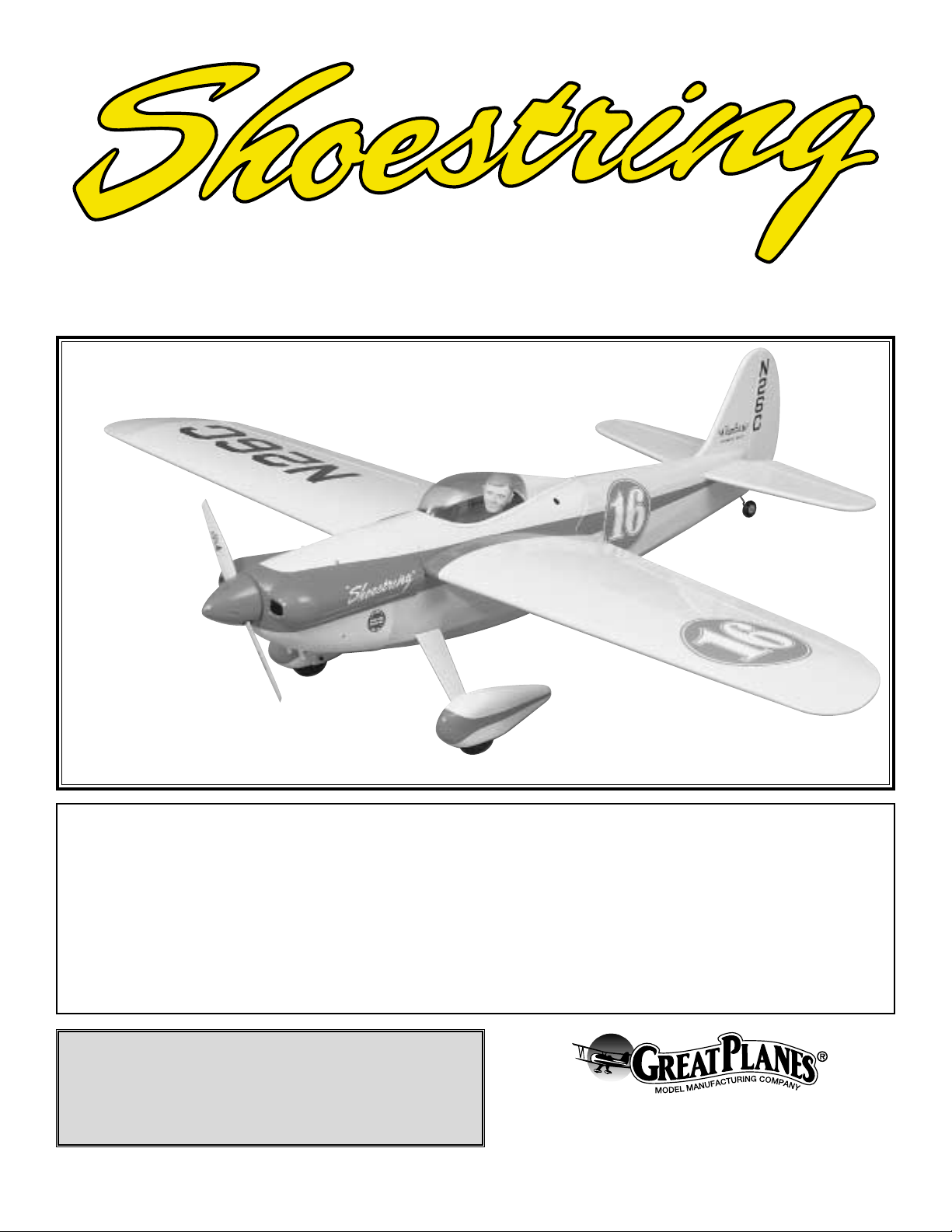
INSTRUCTION MANUAL
A. R. F.
Almost Ready to Fly
Wingspan: 61.5" [1,560mm]
Wing area: 712.5" [46 sq dm]
Weight: 7 lbs [3,630g]
Wing loading: 25.9 oz/sq ft [79 g/sq cm]
Length: 53" [1,345mm]
Radio: 4-ch (five servos)
Engine: .61 two-stroke, .91 four-stroke [10cc 2-stroke, 15cc 4-stroke]
Page 2
INTRODUCTION................................................................2
IMPORTANT SAFETY PRECAUTIONS............................2
ADDITIONAL ITEMS REQUIRED.....................................3
Muffler ................................................................................3
Hardware and Accessories................................................4
Adhesives and Building Supplies.......................................4
Optional Supplies and Tools...............................................4
IMPORTANT BUILDING NOTES.......................................4
ORDERING REPLACEMENT PARTS ...............................4
KIT CONTENTS .................................................................5
PREPARATIONS................................................................6
BUILD THE WING..............................................................6
Hook up the Ailerons..........................................................6
Join the Wing......................................................................7
BUILD THE FUSELAGE....................................................8
Mount the Wing..................................................................8
Mount the Stab and Fin......................................................9
Mount the Wheel Pants and Landing Gear......................12
Finish the Cockpit.............................................................13
Mount the Engine.............................................................15
Mount the Cowl................................................................15
FINAL ASSEMBLY ..........................................................17
Install the Radio ...............................................................17
Finishing Touches.............................................................19
GET THE MODEL READY TO FLY..................................19
Check the Control Directions ...........................................19
Set the Control Throws.....................................................19
Balance the Model (C.G.).................................................20
Balance the Model Laterally.............................................21
PREFLIGHT.....................................................................21
Identify Your Model...........................................................21
Charge the Batteries........................................................21
Balance Propellers...........................................................21
Ground Check..................................................................21
Range Check....................................................................21
ENGINE SAFETY PRECAUTIONS.................................21
AMA SAFETY CODE ......................................................22
CHECK LIST ....................................................................22
FLYING.............................................................................23
Takeoff..............................................................................23
Flight..................................................................Back Cover
Landing..............................................................Back Cover
Thank you for purchasing the Great Planes Shoestring ARF.
Those who know the full-size Shoestring and are familiar
with its history are likely to be racers who may hav e resisted
the idea of building an ARF. On the other hand, such a
beautiful plane can't be resisted no matter how it is
constructed! The Shoestring is nostalgic and modern at the
same time.While the Shoestring made its name as a pylon
racer in 1949 and into the fifties, even today the Shoestring
looks just as “mean”as any other modern-day racer.Though
it is an ARF, the Shoestring can still be “scaled-out” if one
wishes to go the extra mile by adding home-made details
such as landing gear fairings and an air scoop. Note: The
Shoestring is covered in TopFlite Red (TOPQ0201, 6’ roll)
and Cub Yellow (TOPQ0220, 6’roll) MonoKote film.
The full-size Shoestring has a wingspan of 19' (228"). This
model has a wingspan of 61.5". That makes it slightly larger
than quarter-scale (1:3.7 to be exact) and eligible to participate
in IMAA events.
For the latest technical updates or manual corrections for
the Shoestring, visit the web site listed below and select the
Great Planes Shoestring ARF. A “tech notice” box will
appear in the upper left corner of the page if there is new
technical information or changes.
http://www.greatplanes.com/airplanes/index.html
1. The Shoestring ARF should not be considered a toy, but
rather a sophisticated, working model that functions very
much like a full-size airplane. Because of its performance
capabilities, the Shoestring, if not assembled and operated
correctly, could possibly cause injury to yourself or
spectators and damage property.
2. You must assemble the model according to the
instructions. Do not alter or modify the model, as doing so
may result in an unsafe or unflyable model. In a few cases the
instructions may differ slightly from the photos. In those
instances the written instructions should be considered correct.
3. You must take time to build straight, true and strong.
4. You must use an R/C radio system that is in first-class
condition, and a correctly sized engine and components
(fuel tank, wheels, etc.) throughout the building process.
5.You must properly install all R/C and other components so
that the model operates properly on the ground and in the air.
PRO TECT YOUR MODEL,YOURSELF
& OTHERS...FOLLOW THESE
IMPORTANT SAFETY PRECAUTIONS
INTRODUCTIONTABLE OF CONTENTS
2
Page 3
6. You must check the operation of the model before every
flight to insure that all equipment is operating and that the
model has remained structurally sound. Be sure to check
clevises or other connectors often and replace them if they
show any signs of wear or fatigue.
7. If you are not already an experienced R/C pilot, you
should fly the model only with the help of a competent,
experienced R/C pilot.
8. While this kit has been flight tested to exceed normal use,
if the plane will be used for extremely high stress flying, such
as racing, the modeler is responsible for taking steps to
reinforce the high stress points.
Remember:Take y our time and follow the instructions to
end up with a well-built model that is straight and true.
If you have not flown this type of model before, we
recommend that you get the assistance of an experienced
pilot for your first flights. If you're not a member of a club,
your local hobby shop has information about clubs in your
area whose membership includes experienced pilots.
In addition to joining an R/C club, we strongly recommend
you join the AMA (Academy of Model Aeronautics). AMA
membership is required to fly at AMA sanctioned clubs.
There are over 2,500 AMA chartered clubs across the
country. Among other benefits, the AMA provides insurance
to its members who fly at AMA sites and events .Additionally,
training programs and instructors are available at AMA club
sites to help you get started the right way. Contact the AMA
at the address or toll-free phone number below:
Academy of Model Aeronautics
5151 East Memorial Drive
Muncie, IN 47302-9252
Tele. (800) 435-9262
Fax (765) 741-0057
Or via the Internet at:
http://www.modelaircraft.org
The Great Planes Shoestring ARF is an excellent sportscale model.Though it isn't particularly large, it is larger than
quarter-scale making it eligible to fly in IMAA events. The
IMAA (International Miniature Aircraft Association) is an
organization that promotes non-competitive flying of giantscale models. If you plan to attend an IMAA event, contact
the IMAA for a copy of the IMAA Safety Code at the
address or telephone number below.
IMAA
205 S. Hilldale Road
Salina, KS 67401
(913) 823-5569
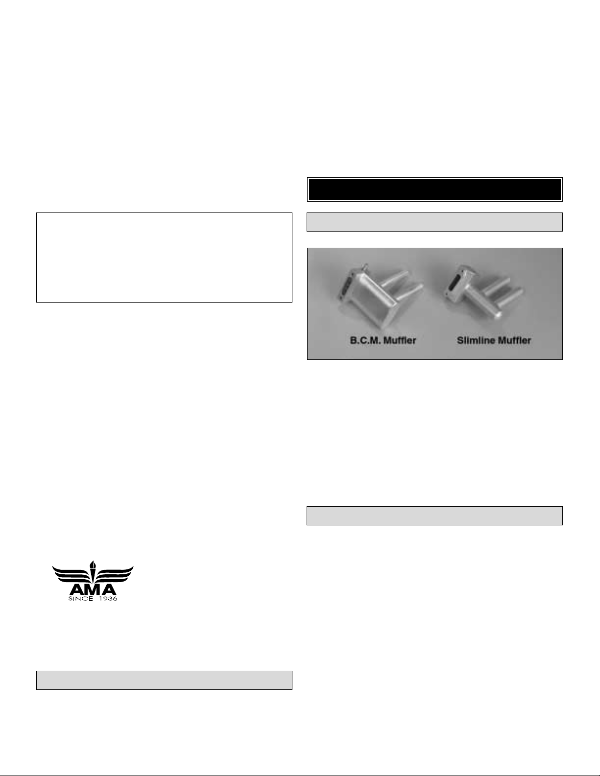
Conveniently, the O.S.®MAX .61FX engine fits inside the
cowl. Engines with similar proportions will fit as well.
However, the cowl will have to be trimmed to fit the exhaust
system. On our prototype, we used the B.C.M. (Bisson
Custom Mufflers) #04061 Pitts muffler for the O.S. .61 FX
(BISG4061). Another muffler that will work is the Slimline
#3217 (SLIG2217) Pitts Style (for O.S. .61 SF, FP, FX). To
use these mufflers, a portion of the included Great Planes
60-120 engine mount will have to be trimmed to
accommodate the muffler.See page 17 for details.
This is the list of hardware and accessories required to finish
the Shoestring ARF. Order numbers are provided in
parentheses for your convenience.
❏ Four-channel radio with five servos (two aileron servos)
❏ .61 two-stroke to .91 four-stroke engine
❏ Muffler
❏ Suitable propellers (refer to the engine manufacturer's
recommendations)
❏ 3' Medium fuel tubing (GPMQ4131)
❏ Y-harness for dual aileron servos (HCAM2500 for Futaba
®
J)
❏ 1/4-scale pilot (optional, WBRQ2626)
❏ R/C foam rubber (1/4" - HCA Q1000, or 1/2" - HCA Q1050)
❏ Easy Fueler fuel filler valve for glow fuel (GPMQ4160)
❏ Switch and charge jack mounting set (GPMM1000)
❏ 1/4" yellow Kwik Stripe striping tape (for canopy trim,
GPMQ1450)
Hardware and Accessories
Muffler
ADDITIONAL ITEMS REQUIRED
IMAA Information
Note: We, as the kit manufacturer, provide you with a top
quality kit and instructions, but ultimately the quality and
flyability of your finished model depends on how y ou b uild it;
therefore, we cannot in an y w ay guarantee the performance
of your completed model, and no representations are
expressed or implied as to the performance or safety of y our
completed model.
3
Page 4
To order replacement par ts for the Great Planes Shoestring ARF, use the order numbers in the Replacement Parts List
that follows. Replacement par ts are available only as listed. Not all parts are available separately (an aileron cannot be
purchased separately, but is only available with the wing kit).Replacement par ts are not available from Product Support,
but can be purchased from hobby shops or mail order/Internet order firms. Hardware items (screws, nuts, bolts) are also
available from these outlets. If you need assistance locating a dealer to purchase par ts, visit www.greatplanes.com and
click on “Where to Buy.” If this kit is missing parts, contact Great Planes Product Support.
Replacement Parts List
Order Number Description How to Purchase
Missing pieces ......................Contact Product Support
Instruction manual.................Contact Product Suppor t
Full-size plans.......................Not available
GPMA2210......................................Wing Kit
GPMA2211......................................Fuse Kit
GPMA2212......................................Tail Set Contact Your Hobby
GPMA2213......................................Cowl Supplier to Purchase
GPMA2214......................................Canopy These Items
GPMA2215......................................Landing Gear
GPMA2216......................................Wheel Pants
In addition to common household tools and hobby tools, this
is the “short list”of the most important items required to build
the Shoestring. Great Planes Pro™CA and Epoxy glue
are recommended.
❏ 1/2 oz. Thin Pro CA (GPMR6001)
❏ 1/2 oz. Medium Pro CA (GPMR6007)
❏ 30-Minute Epoxy (GPMR6047)
❏ Drill bits, 1/16", 5/64", 3/32", 1/8", #29 (or 9/64") and 8-32
tap (or Great Planes 8-32 tap and drill set, GPMR8103),
3/16", #11 (or 13/64"), 7/64" (or 1/4"), 7/32"
Here is a list of additional optional items we used to
assemble the Shoestring ARF.
❏ 21
ST
Century®sealing iron (COVR2700)
❏ 21
ST
Century iron cover (COVQ2702)
❏ Milled Fiberglass (GPMR6165)
❏ Microballoons (TOPR1090)
❏ Builders Triangle Set (HCAR0480)
❏ Dead Center
™
Engine Mount Hole Locator (GPMR8130)
❏ Threadlocker (GPMR6060)
❏ K & S #801 K e vlar thread (f or stab alignment K+SR4575)
❏ Denatured Alcohol (for epoxy clean up)
❏ Curved Tip Scissors for Trimming Canopy (HCAR0667)
❏ R/C-56 Canopy Glue (JOZR5007)
❏ Great Planes CG Machine
™
(GPMR2400)
❏ Great Planes AccuThrow
™
Deflection Gauge (for measuring
control throws, GPMR2405)
❏ Top Flite Precision Magnetic Prop Balancer
™
(TOPQ5700)
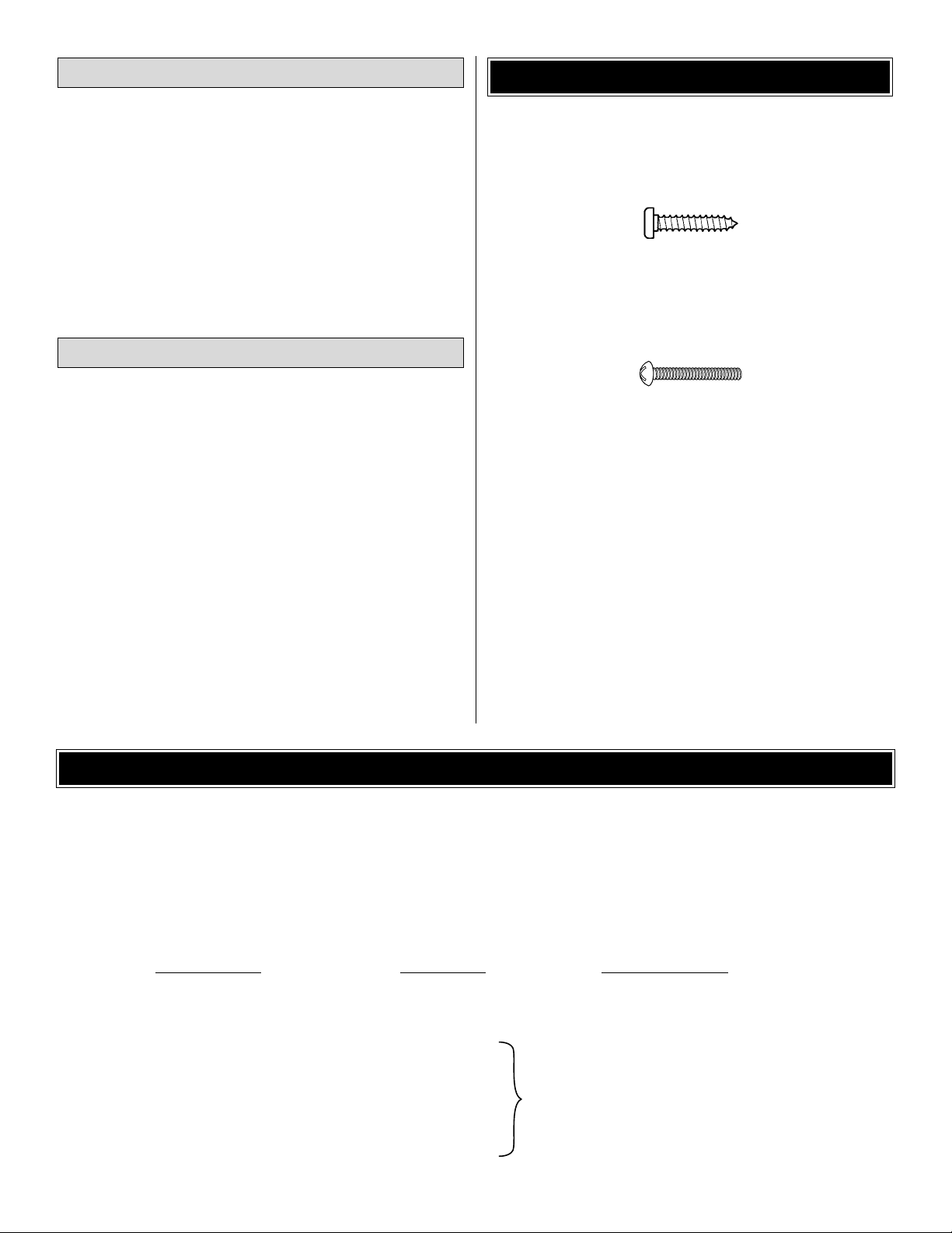
• There are two types of screws used in this kit:
Sheet metal screws are designated by a number and a
length. For example #6 x 3/4"
This is a number six screw that is 3/4" long.
Machine screws are designated by a number, threads per
inch, and a length. For example 4-40 x 3/4"
This is a number four screw that is 3/4" long with
forty threads per inch.
• Whenever the term
glue
is written you should rely upon
your experience to decide what type of glue to use.When a
specific type of adhesive works best for that step, the
instructions will make a recommendation.
• Whenever just
epoxy
is specified you may use
either
30-minute epoxy or6-minute epoxy.When 30-minute epoxy
is specified it is highly recommended that you use only 30minute (or 45-minute) epoxy, because you will need the
working time and/or the additional strength.
• Photos and sketches are placed before the step they
refer to. Frequently you can study photos in following steps
to get another view of the same parts.
IMPORTANT BUILDING NOTES
Optional Supplies and Tools
Adhesives and Building Supplies
4
ORDERING REPLACEMENT PARTS
................
Page 5
5
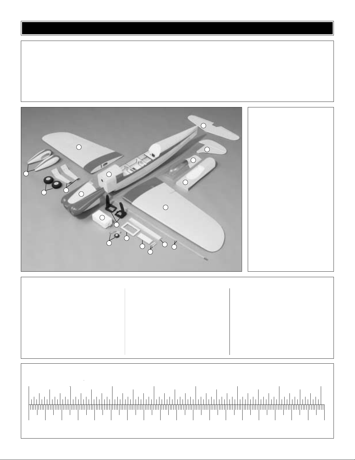
1 Wing with Ailerons
2 Fuselage
3 Stab with Elevators
4 Fin with Rudder
5 Painted Cowl
6 Painted Canopy
7 Cockpit
8 Painted Wheel Pants (2)
9 Painted Aluminum Landing
Gear (2)
10 1/4" x 1-1/8" x 10-3/4"
Wing Joiner
11 Fuel Tank with Hardware
12 Tail Gear with Wheel
13 Plywood Servo Tray
14 Engine Mount
15 3" Wheel (2)
16 1/8" Plywood Wing Bolt Plate
17 .074" x 36" Elevator and
Rudder Pushrods
18 Wing Dowels
1/8" x 7/8" x 6" Ply strip (wheel pant mounts)
(4) 1/2" x 1/2" x 5/8" Maple blocks (cowl mnts)
1/4" x 3/4" x 5" Balsa stick (fuel tank support)
3" Spinner
(2) 2" x 3/16" Bolt-on axles
(4) 3/16" Wheel collars
(4) 6-32 Set screws for wheel collars
(2) 5/16" -24 Lock nuts (for axles)
(2) 1/4-20 x 2" Nylon wing bolts
(4) Large control horns
(6) 6-32 Blind nuts (preinstalled)
(2) 1/4-20 Blind nuts (preinstalled)
(8) 8-32 x 1" SHCS (socket-head cap screws)
(4-engine mnt to firewall, 4-engine to mnt)
(4) Faslinks
(5) Nylon clevis
(1) 2" x 9" CA hinge strip
(4) 8-32 Blind nuts (engine mount)
(6) 6-32 x 3/4" Screws (landing gear)
(4) 2-56 x 5/8" Screws (elev, rudd control horns)
(4) #2 x 1/2" Screws (aileron control horns)
(4) #2 x 3/8" Screws (wheel pants)
(5) Silicone retainers (clevises)
(4) #8 Flat washers (engine mount)
(1) 3/32" Wheel collar (tail wheel)
(1) 4-40 Set screw (tail wheel)
(1) Brass body screw-lock conn.(throttle servo)
(1) Nylon retainer (screw-lock connector)
(1) 4-40 x 1/4" SHCS (screw-lock connector)
(2) .074" x 6" Pushrod (ailerons)
(1) 3/16" x 12" Guide tube (throttle)
(1) .074" x 18" Pushrod (throttle)
(8) #8 Lock washers (engine, engine mount)
(1) Elevator joiner wire
(4) #4 x 3/8" Screws (cowl)
(4) #4 Washers (cowl)
Kit Contents
(Photographed)
Kit Contents (Not Photographed)
0" 1" 2" 3" 4" 5" 6" 7"
0 10 20 30 40 50 60 70 80 90 100 110 120 130 140 150 160 170 180
Inch Scale
Metric Scale
To convert inches to millimeters, multiply inches by 25.4
Before starting to build, use the Kit Contents list to take an inventory of your kit to make sure it is complete, and inspect
the parts to make sure they are of acceptable quality. If any parts are missing or are not of acceptable quality, or if you
need assistance with assembly, contact Great Planes Product Support. When reporting defective or missing parts, use
the part names exactly as they are written in the Kit Contents list on this page.
Great Planes Product Support:
Phone: (217) 398-8970
Fax: (217) 398-7721
E-mail: airsupport@greatplanes.com
KIT CONTENTS
3
1
8
15
9
5
2
7
1
11
14
12
13
16
10
18
17
4
6
Page 6
❏ 1. If you have not done so already, remove the major
parts of the kit from the box (wings, fuse, wheel pants, cowl,
tail parts, etc.) and inspect them for damage.If any parts are
damaged or missing, contact Product Support at the
address or telephone number listed on the front cover.
❏ 2. Remove the masking tape and separate the ailerons
from the wing, the rudder from the fin and the elevators from
the stab. Use a covering iron with a covering sock on high
heat to tighten the covering. Apply pressure over sheeted
areas to thoroughly bond the covering to the wood. Hint:
Poke three or four pin holes in the covering between the
“ribs” in the tail surfaces and ailerons. This will allow air to
escape while tightening the covering.
Do the right wing first so yours matches the photos the
first time through. You can do one wing at a time, or
work on them together.
❏❏1. Drill a 3/32" hole, 1/2" deep in the center of each
hinge slot to allow the CA to “wick” in. Follow-up with a #11
blade to clean-out the slots. Hint: If you have one, use a
high-speed rotary tool to drill the holes.
❏❏2. Use a sharp #11 blade to cut a strip of covering
from the hinge slots in the wing and aileron.
❏❏3.Cut three 3/4" x 1" hinges from the CA hinge strip.
Snip off the corners so they go in easier.
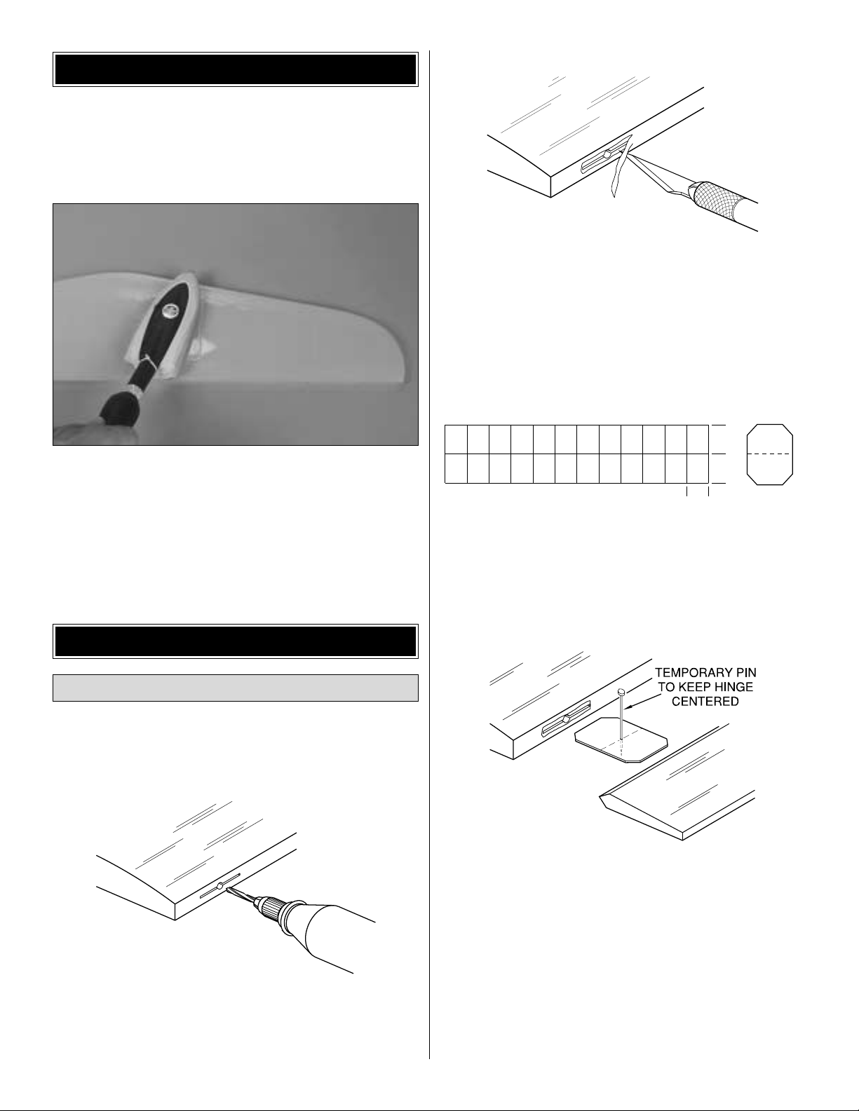
❏❏4. Test fit the ailerons to the wing with the hinges. If
the hinges don't remain centered, stick a pin through the
middle of the hinge to hold it in position.
❏❏5. Remove any pins you may have inserted into the
hinges. Adjust the aileron so there is a small gap between
the LE of the aileron and the wing. The gap should be
small—just enough to see light through or to slip a piece of
paper through.
1"
1"
3/4"
AWAY FROM THE SLOT
CUT THE COVERING
DRILL A 3/32" HOLE
1/2" DEEP, IN CENTER
OF HINGE SLOT
Hook Up the Ailerons
BUILD THE WING
PREPARATIONS
6
Page 7
❏❏6. Apply six drops of thin CA to the top and bottom of
each hinge. Do not use CA accelerator. After the CA has
fully hardened, test the hinges by pulling on the aileron.
❏❏7.Cut the covering 1/8" inside the opening in the wing
for the aileron servo.Use a trim iron to seal the covering to
the edges of the opening. Cut the covering from the hole in
the bottom of the wing for the aileron servo wire.
❏❏8. Tie the string inside the wing to the aileron servo
wire. Pull the servo wire out of the end of the wing with the
string. Drill 1/16" holes in the wing for the servo mounting
screws, then mount the aileron servo using the screws that
came with it.
❏❏9. Dr ill 1/16" holes into the bottom of the aileron for
mounting the nylon control horn. Before mounting the horn,
use a pin to poke several holes through the covering in the
mounting location. Saturate the holes with thin CA, wipe
away residual CA and allow to fully harden. Mount the
aileron control horn to the aileron with two #2 x 1/2" screws.
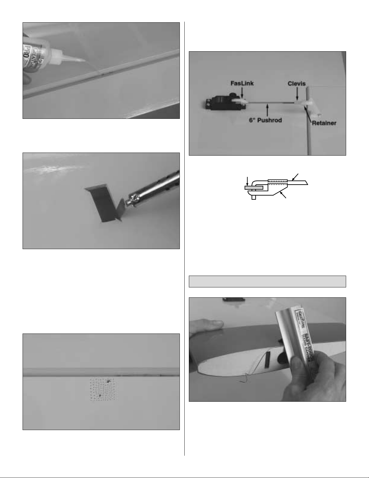
❏❏10. Enlarge the hole in the servo arm with a Hobbico
Servo Horn Drill (or a #48 or 5/64" drill bit). Connect the
aileron to the servo with a 6" pushrod, a FasLink, a clevis
and a silicone retainer.
❏ 11. If you haven't yet done so, go back to step 1 and
assemble the other wing the same way.
❏ 1. Trim the covering from the ribs on the end of both
wings.This is easily done with a sanding block and mediumgrit sandpaper as shown.
❏ 2. Test fit the wing halves with the hardwood joiner. Be
certain the joiner is installed upright (the bottom of the joiner
has an angle for wing dihedral).
Join the Wing
FasLink
2-56 (.074") Pushrod Wire
Servo Horn
7
Page 8
❏ 3. Prepare 1/2 oz. of 30-minute epoxy. Add 1/2 oz. of
microballoons.Working quickly, thoroughly coat the inside of
both wing halves where the joiner fits and one half of the
joiner with the epoxy and microballoons mixture. Making
certain the joiner is upright, insert the coated end into one of
the wing halves. Coat the other end of the joiner with the
remainder of the epoxy and microballoons mixture.Proceed
immediately to the next step.
❏ 4. Prepare an additional 1/4 oz. of 30-minute epoxy only
(no microballoons). Coat the ribs on both ends of the wing
with the epoxy. Join the wing halves tightly, holding them
together. Use a paper towel to wipe away excess epoxy that
comes out of the wing. Tightly hold the wing together with
masking tape, making certain both halves are in full contact
and that the leading edges and trailing edges align. Wipe
away e xcess epo xy and do not disturb the wing until the epoxy
has fully hardened.
❏ 5. Connect the servo wires to a Y-harness (HCAM2500
for Futaba). Secure the connection between the servo wire
and the Y-harness with heat shrink tubing, tape or clips
suitable for that purpose.
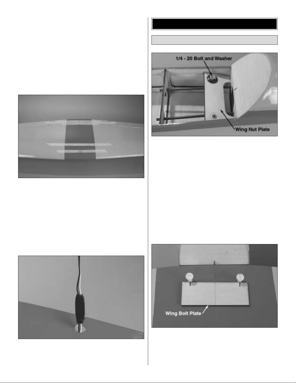
❏ 1.Inspect the blind nuts that are pressed into the bottom
of the wing nut plate inside the fuselage. If the nuts are not
securely pressed into the plate, remove them. Apply a dab
of 30-minute epoxy to the flange around the blind nuts, then
reinsert them into the plate. Use a metal 1/4-20 bolt and a
large washer to draw the blind nuts all the way up into the
wood by tightening the bolt to the top of the plate.
❏ 2. Cut the covering from the holes in the leading edge of
the wing for the dowels and near the trailing edge for the
wing bolts. Temporarily fit the 1/4" wing dowels into the
leading edge of the wing.
❏ 3. T est fit the wing to the fuse and bolt it into position with
the 1/4-20 nylon wing bolts. If necessary, enlarge or adjust
the wing bolt holes in the wing so the wing bolts will align
with the blind nuts.
❏ 4. Unscrew the wing bolts about 1/2". Place the 1/8"
plywood wing bolt plate on the wing centered on the wing
bolts. Mar k the location of the wing bolts on the plate.
❏ 5. Drill 17/64" (or 1/4") holes through the center of the
wing bolt plate at the marks (see the photo at step 7).
Mount the Wing
BUILD THE FUSELAGE
8
Page 9

❏ 6. Use a hobby knife with a sharp #11 blade to cut the
covering from the wing where the wing bolt plate will fit. Be
certain to cut only through the covering, not into the wood.
❏ 7. Remove the covering and use epoxy to glue the wing
bolt plate to the wing. Hint: Use the wing bolts themselves
as clamps to hold the wing bolt plate into position until the
epoxy hardens.Be certain you do not epoxy the wing to the
fuse or the bolts to the wing!
❏ 1. Cut the covering from the slots in the fuse for the stab
and fin and from the guide tubes for the pushrods.Hint: Cut
the covering from the slots for the stab and fin 3/32" from the
edge, thus leaving a
flap
that can be ironed to the stab and
fin after gluing them into position.
❏ 2. Cut a round groove or a notch in the fuse at the TE of
the stab to accommodate the elevator joiner wire.
❏3.Fit the stab into the fuse.Center the trailing edge by taking
accurate measurements as shown in “X”= “X”in the sketch.
❏ 4. Bolt the wing to the fuse. Place the model in a building
stand (such as a Robart Super Stand II, ROBP1402). Stand
five to ten feet behind the model and view the stab and wing. If
the stab and wing align with each other, proceed to the next
step. If the stab and wing do not align, place a weight on the
“high”side of the stab to bring it into alignment. If much weight
is required, remove the stab and sand the “high side”of the slot
in the fuse where the stab fits until the stab aligns with the wing.
X
X
X = X
ROUND
Mount the Stab and Fin
9
Page 10

❏ 5. Stick a pin into the top of the fuse centered in the
middle stringer at the front of the wing. Tie a small loop in
one end of a 42" piece of non-elastic string such as K & S
#801 Kevlar thread (K+SR4575). Slip the loop in the str ing
over the T-pin.
❏ 6.Fold a piece of masking tape over the other end of the
string and draw an arrow on it.Slide the tape along the string
and align the arrow with one end of the stab as shown in the
photo. Swing the string over to the same position on the
other end of the stab.While keeping the stab centered from
side-to-side, adjust the stab and slide the tape along the
string until the arrow aligns with both sides. Be cer tain the
stab remains centered from side-to-side during this process.
❏ 7. Use a fine-point felt-tip pen such as a Top Flite Panel
Line Pen (TOPQ2510) to mar k the outline of the fuse onto
the top and bottom of the stab.
(Disregard the elevators, fin
and rudder in the photo - they should not be mounted to the
model yet.)
❏ 8. Remove the stab from the fuse. Use a sharp #11
hobby knife or use the Expert Tip that follows to cut the
covering from the stab along the lines you marked.Use care
to cut only into the covering and not into the wood.
How to cut covering from balsa.
Use a soldering iron to cut the covering from the stab.The
tip of the soldering iron doesn't have to be sharp, but a fine
tip does work best. Allow the iron to heat fully. Use a
straightedge to guide the soldering iron at a rate that will just
melt the covering and not burn into the wood.The hotter the
soldering iron, the faster it must trav el to melt a fine cut.Peel
off the covering (see the photo at step 11).
❏ 9. The same as you did for the wing and fuse, cut the
covering from the hinge slots in the stab and elevators and
the fin and rudder.There should be three hinge slots in the
rudder and in both elevators and two hinge slots in the fin.
There should also be a hinge slot in the fuse that aligns with
the bottom hinge slot in the rudder.Drill 3/32" holes through
the middle of the slots.
❏ 10. Cut nine more CA hinges from the CA hinge str ip.
Temporarily join the elevators to the stab with the hinges.
10
Page 11

❏ 11. Position the elevator joiner wire, evenly spaced,
over both elevators as shown in the photo. Mark the ends of
the joiner wire onto the elevators.
❏ 12. Drill a 1/8" hole through the LE of both elevators at
the marks you made. Use a Great Planes Groove Tube
(GPMR8140) or a 1/8" brass tube sharpened on the end to
cut a groove in the LE of the elevators to accommodate the
joiner wire.Test fit elevators to stab with joiner wire.“Tweak”
the joiner wire if necessary to get both elevators even.
❏ 13. Use 30-minute epoxy to glue the stab into the fuse.
For the most strength, apply epoxy to both sides of the stab
and inside the fuse where the stab fits. Slide the stab and
the elevator joiner wire into position. Wipe away residual
epoxy with a tissue dampened with alcohol. If the stab
required a weight on one side or the other to align it with the
fuse, position the weight. Use the pin and string to confir m
stab alignment. If you've cut the covering as suggested over
the slots in the fuse for the stab (leaving a 3/32"
flap
that can
be ironed to the stab), use a trim iron to iron the covering to
the stab before the epoxy hardens .Do not disturb the model
until the epoxy has fully hardened.
❏ 14. Thoroughly coat the insides of the holes in the
elevators for the joiner wire with 30-minute epoxy. Also coat
the ends of the joiner wire that go into the elevators .Join the
elevators to the stab and the joiner wire with the hinges.
Wipe away excess epoxy before it hardens. The same as
you did the ailerons, permanently join the elevators to the
stab by gluing in the hinges with thin CA.
❏ 15. Fit the fin into the fuse. Just the same as you did the
stab, mark the outline of the fuse onto the fin, then use the
soldering iron technique to remove the covering.Glue the fin
into position with 30-minute epoxy using a builder's square
to make certain the fin is vertical. If necessary, pull the fin to
one side or the other with masking tape until the fin is
perpendicular to the stab.
❏ 16. Use a #11 blade or a small razor saw to cut a slot in
the aft end of the fuse for the nylon bearing on the tail gear
wire.Test fit the tail gear wire into the fuse as shown.
11
Page 12

❏ 17. The same as the elevators, drill a 3/32" hole in the
rudder for the tail gear wire and cut a groove to accommodate
the bearing.
❏ 18. Apply petroleum jelly to the tail wheel bearing where
the wire passes through.This will prevent the wire from being
glued to the bearing. Permanently join the rudder to the fin
using 30-minute epoxy to glue the “arm” portion of the tail
gear wire into the rudder.Use thin CA to glue in the hinges.
❏❏1. Cut two 1-3/8"-long wheel pant mounts from the
1/8" x 7/8" x 6" plywood strip.Stack one mount on top of the
other, then drill a 3/16" hole through the center of both
mounts at the same time. Enlarge the hole in one of the
mounts to 1/2".Note: Drawing diagonal lines, from corner to
corner as shown, will help locate the center of the wheel
pant mounts.
❏❏2. Glue the mounts together with the holes centered
over each other.
❏❏3. Holding one of the wheel pants as shown in the
photo (with the front of the pant toward the left), insert a
wheel into the pant and center it in the opening.Use a felt-tip
pen to mark the side of the pant over the hole in the wheel.
Refer to these photos for the following two steps.
❏❏4. Use a high-speed rotary tool with a cutting bit or a
hobby knife to cut a 1/2" hole centered over the mark 1/2"
from the bottom of the pant.This is now the right wheel pant.
❏❏5. Round the bottom edge of the wheel pant mount so it
fits in the pant when the 1/2" hole in the mount is centered over
the hole in the pant.Glue the mount to the pant with 30-minute
epoxy. Hint: For the most secure bond, add microballoons
(TOPR1090) or milled glass fibers (GPMR6165) to the epoxy.
❏❏6. Drill 3/32" holes through the right landing gear on
both sides of the large hole for the axle.
Mount the Wheel Pants & Landing Gear
12
Page 13

❏❏7. Use a metal saw or a high-speed rotar y tool with a
reinforced cut-off wheel to cut 5/16" from one of the bolt-on
axles. Mount the axle to the landing gear with a nut.
❏❏8. Use a #11 (or 13/64") drill to enlarge the hole in the
wheel.Temporarily slide the wheel pant, a wheel collar and a
wheel onto the axle. Deter mine where the set screw for the
second wheel collar that holds on the wheel will be positioned
on the axle. Remove the wheel and pant, then file a flat spot
on the axle for the set screw in the wheel collar.
❏❏9. Mount the wheel and pant to the axle with a wheel
collar on both sides of the wheel.Temporarily tighten the set
screws in the wheel collars.
❏ 10.Return to step 1 and mount the other wheel and pant
to the left landing gear the same way. Be cer tain to make a
left wheel pant.
❏ 11.Mount the landing gear to the fuse with six 6-32 x 3/4"
screws. Mount the tail wheel to the tail gear wire with the
wheel collar and set screw.
❏ 12.Place the model on its gear on the workbench. Prop-
up the tail until the fuse is level.Adjust both wheel pants so
they are level with the workbench.
❏ 13. Without moving the wheel pants, mark the locations
of the holes in the landing gear onto the wheel pants.
❏ 14.Drill 1/16" holes through the pants and the wheel pant
mounts at the marks you made (it may be easier to remove
the landing gear from the fuselage for this).
❏ 15. Fasten the wheel pants to the landing gear with
#2 x 3/8" screws. Remove the set screws in the wheel
collars, and add a drop of oil to the axles and the wheels.
Add a drop of threadlocker to the set screws, install them
into the wheel collars and securely tighten.
Refer to this photo while finishing the cockpit and
gluing in the pilot.
❏ 1. Paint the inside of the cockpit black. Caution: Most
types of paint will soak through the balsa and show through
the covering. To avoid this, first clear-coat the inside of the
cockpit before painting it black.
❏ 2. After the black paint inside the cockpit fully dries, apply
the instrument panel decal.
Finish the Cockpit
13
Page 14

❏ 3. Use curved-tip scissors to cut out the canopy. Be
certain to leave approximately a 1/4" rim all the way around
the canopy for a gluing surf ace to the coc kpit.True the edges
by sanding with medium-grit sandpaper.
❏ 4. Test fit the pilot but do not yet glue him into position.
We used a Williams Brothers' 1/4-scale pilot (WBRQ2626).
Unless a portion of the cockpit floor is removed, there is
room for only his head, not his bust.On the prototype shown
in this manual, we simply cut a round hole in the cockpit floor
for his neck.Position the canopy on the cockpit to be certain
the pilot does not contact the canopy. Make adjustments
where necessary.
❏ 5. Paint the pilot and securely glue him into position.
❏ 6. Place the canopy on the cockpit.Use a fine-point felt-tip
pen to lightly trace the outline of the canopy onto the cockpit.
❏ 7. Remove the canopy. Use a pin to poke several holes
through the covering all the way around the cockpit 3/32"
inside the line you marked. These holes will help the glue
adhere to the cockpit when it's time to glue the canopy on.
Use a tissue dampened with alcohol to wipe away the ink line .
❏ 8. Wash the canopy in warm, soapy water. Glue the
canopy to the cockpit with R/C-56 Canop y Glue (JOZR5007).
CA could be used, but great care must be taken not to f og the
canopy or use too much CA which could run onto the canopy
or the covering. Canopy glue provides working time and can
be wiped away with a damp tissue before it dries.Use rubber
bands, weights or whatever method appropriate to hold the
canopy to the cockpit until the glue dries.
❏ 9. Use epoxy to glue the wing dowels into the wing with
1/4" protruding from the LE.
❏ 10.Mount the wing to the fuse.Position the cockpit on the
wing. Accurately align the cockpit with the fuselage. Use a
felt-tip pen to mark the outline of the cockpit onto the wing.
❏ 11. Remove the cockpit and the wing from the fuse. Use
the “soldering iron and straightedge” technique to cut the
14
Page 15

covering 1/16" inside the lines you marked. Make an
additional cut 1/2" inside of the cuts already made. Peel the
covering from the wing to expose the balsa wing sheeting.
12.Mount the wing to the fuse.Use epoxy to glue the cockpit
to the wing.
❏1.T urn to page 23 and cut the engine mount template from
the manual. Use spray adhesive or tape to temporarily attach
the template to the firewall with the vertical and horizontal lines
on the template aligned with the lines on the firewall.
❏ 2.Use a small punch or a wire sharpened on one end to
transfer the engine mount bolt holes to the firewall by
making dimples in the wood. Remove the template.
❏ 3.Drill 7/32" holes through the firewall at the marks.Install
four 8-32 blind nuts into the holes on the back of the firewall.
Refer to this photo for the following two steps.
❏ 4. Mount the engine mount to the firewall with four
8-32 x 1" SHCS (socket-head cap screws), #8 lock washers
and #8 flat washers, but do not fully tighten the bolts.Place
the back plate of the spinner on the engine.Adjust the width
of the mount to fit the engine. Center the molded-in “tick”
marks on the engine mount over the horizontal line on the
firewall.Tighten the mounting bolts.
❏ 5. Use small clamps or another method to temporarily
secure the engine to the mount with the back plate of the
spinner 5-11/16" from the firewall.Use a Great Planes Dead
Center™Engine Mount Hole Locator (GPMR8130) or
another method to mark the engine mount holes onto the
engine mount.
❏ 6. Remove the engine from the mount. Drill #29 holes
through the mount at the marks you made.Tap 8-32 threads
into the mount. Mount the engine to the mount with four
8-32 x 1" socket head cap screws and #8 lock washers.
❏ 1. Use epoxy to glue the four 1/2" x 1/2" x 5/8" maple
cowl mounting blocks to the firewall where shown. Before
gluing the top two blocks, sand them to a curved shape to
match the top of the fuse.Also note that the top left block will
have to be trimmed to accommodate the engine mount.
Mount the Cowl
Mount the Engine
15
Page 16

❏ 2. Hold a ruler to the fuse centered on one of the cowl
mounting blocks. Use a felt-tip pen to draw a line directly
onto the fuse along the straightedge.
❏ 3. Mark a reference point on the end of the line exactly
6" from the center of the cowl mounting block.
❏ 4.Mark the location of the remaining three cowl mounting
blocks the same way.
❏ 5.Place the cowl on the fuse.Mount the spinner and prop
to the engine. Position the cowl on the fuse so it is in
alignment with the spinner. Be certain there is at least a
3/32" gap between the front of the cowl and the back plate
of the spinner.It may be helpful to have an assistant hold the
cowl for you.
❏ 6. Align the ruler with the line on the fuselage. Mark the
center of the cowl mounting block on the cowl 6" from the
reference point. Drill a 3/32" hole through cowl and the
mounting block at the mark.Enlarge the hole in the cowl only
with a 1/8" drill. Mount the cowl to the block with a #4 x 3/8"
screw and #4 washer.
❏ 7.With your assistant holding the cowl in position, mark,
drill and mount the cowl to the remaining three cowl
mounting blocks the same way.
Before finishing the cowl, now is a good time to install the
fuel tank...
❏ 8. Arrange the stopper and tubes as shown in the photo,
then insert them into in the tank. Tighten the screw to
expand the stopper , thus sealing the tank.Be certain the fuel
line weight (clunk) at the end of the fuel line inside the tank
does not contact the rear of the tank. Otherwise, the line
may become stuck above the fuel level and discontinue fuel
flow. Remember (or use a felt-tip pen to mark) which tube is
the fuel pick-up tube and which tube is the vent (that will be
connected to the pressure fitting on the engine muffler).
❏ 9. Install the tank in the fuse. Fit the neck through the
hole in the firewall. Be certain the vent tube inside the tank
is pointing upward. Cut the 1/4" x 3/4" x 5" balsa stick to the
correct length to fit between the fuselage sides under the aft
end of the tank (the approximate length will be 4-11/16").
Position the “fuel tank support” in the fuse, then glue it into
position. If necessary, the support may be broken free to
remove the tank when maintenance is required.
BALSA FUEL
TANK SUPPORT
16
Page 17

❏ 10. Mount the muffler to the engine. A Bisson Custom
Mufflers #04061 Pitts muffler (BISG4061) was selected for the
O.S. .61 FX used on the model shown in this manual (the
muffler can be seen in the following photo). The muffler
supplied with the engine could be used, but this would require
trimming a significant amount of material from the cowl,
detracting from its appearance.Note: Approximately 1/16" of
the engine mount must be ground away to accommodate the
Bisson muffler.This poses no problem as long as the corners
are round as illustrated in the sketch.
❏ 11. Use the filler valve mount from a Great Planes
Handy Mounts set (GPMQ6000), or fashion a mount from
1/8" plywood (not included) for the fuel filler valve. A Great
Planes Easy-Fueler for glow fuel was used on this model
(GPMQ4160, not included with this kit). Use epoxy to
securely glue the filler valve mount to the firewall in a
location where the filler valve will be accessible outside the
cowl when it's time to fuel the engine.
❏ 12. Use epoxy or fuelproof paint to coat the cowl
mounting blocks and the fuel filler mount.
❏ 13. Cut holes in the cowl where necessary for the engine
exhaust, needle valv e, glo w plug igniter (or remote glow plug
hook up if used) and fuel filler valve.
❏ 1. Make the elevatorand rudder pushrods by threading
two nylon clevises approximately 20 full turns onto the end
of two 36" pushrods. Connect each clevis to a large nylon
control horn.
❏ 2. Slide the pushrods into the guide tubes through the aft
end of the fuse. Bend the pushrods as necessary so the
control horns will fit on the rudder and elevator. Drill 3/32"
holes through the rudder and elevator and mount the horns
with 2-56 x 5/8" screws and the nylon mounting plates on
the other side of the control horn.
Install the Radio
FINAL ASSEMBLY
ROUND
17
Page 18

Refer to this photo while mounting the servos.
❏ 3. Test fit the rudder, elevator and throttle servos in the
1/8" plywood servo tray. Make modifications to the tray if
necessary to fit the servos. Use epoxy to glue the servo tray
into the fuse.
❏ 4. Place the ser vos in the tray. Center the elevator and
rudder.If necessary, bend the elevator and rudder pushrods
to align with the holes in the servo arms, then cut the
pushrods so they can be connected to the servos with a
nylon FasLink as shown in the sketch.
❏ 5. Connect the pushrods to the servos. Drill 1/16" holes
through the servo tray for mounting the elevator and rudder
servos. Add a drop of thin CA to each hole and allow to
harden. Mount the servos to the ser vo tray with the screws
that came with the servos.
Hook up the throttle...
❏ 6. Drill a 3/16" hole through the firewall for the throttle
pushrod guide tube. Be certain to not drill into the tank! It
may be helpful to remove the engine for this step, so it does
not interfere with drilling the hole (or use an extended drill bit).
❏ 7. Insert the 3/16" x 12" throttle pushrod guide tube
through the hole in the firewall.Bend the 17" throttle pushrod
as necessary, then connect it to the carb arm on the engine
with a nylon clevis and connect it to the throttle servo with a
screw-lock pushrod connecter.Make a brace for the aft end
of the guide tube from 1/8" leftover balsa or plywood (not
supplied with this kit) and glue it to the former as shown in
the previous photo .Mount the throttle servo to the servo tra y.
❏ 8. Glue the guide tube to the brace and the firewall.
❏ 9. Wrap the battery pack and receiver in at least 1/4" of
R/C foam rubber and install them in the fuselage. On our
model with an O.S. MAX .61 FX, the battery and receiver
were mounted where shown in the photo to minimize the
amount of tail weight required to balance the model at the
correct C.G. (with a 2-stroke engine, a small amount of tail
weight may be required). Securely hold the battery pack and
receiver in position with a balsa stick glued between the fuse
sides. Simply stuffing the receiver and battery pack in place
with additional foam rubber is not a secure method of holding
them down. Note: Be certain that the wing bolts do not
dislodge the balsa stick that holds the battery and receiver in
the fuse.The wing bolts may be shortened if necessary.
❏ 10. Mount the receiver on/off switch. A Great Planes
Switch & Charge Jack Mounting Set (GPMM1000, not
included) was used on this model. Be certain it is in a
location away from engine exhaust.
❏ 11. Make cer tain all the servo arms are secured to the
servos with the screws that came with them and that all the
clevises have retainers on them.
FasLink
2-56 (.074") Pushrod Wire
Servo Horn
18
Page 19

❏ 12. Extend the receiver antenna and guide it out of the
fuselage and connect it to the fin. Be certain there is a strain
relief on the antenna to keep stress off the solder joint inside
the receiver .On our prototype we drilled a 3/32" hole through
the top stringer aft of the cockpit and routed the antenna
through the hole. The end of the antenna was connected to
a hook made from a cut-off servo arm connected to a small
rubber band and a T-pin inserted into the top of the fin.
❏ 1. If you prefer , paint the spinner with LustreKote
®
Missile
Red (TOPR7201) to accurately match the paint and
covering on the plane. Note: The paint on spinners usually
does not hold up well to electric starters, so painted spinners
are best for display only.
❏ 2. Apply the decals. The easiest and most accurate way
to position the decals is to first cut them from the sheet.
When ready to apply one of the decals, submerge it in a tub
of warm water mixed with liquid dish soap (about a
tablespoon of soap per gallon of water) and peel the decal
from the backing.Lay the decal on the model and position it
exactly where you want it. Use a paper towel to wipe away
most of the water, then use a soft balsa sheet or something
similar to squeegee the rest of the water from under the
decal. Allow to dry overnight before flying the model.
❏ 3. Apply 1/4" yellow striping tape (GPMQ1450) around
the base of the canopy.
❏ 1. Turn on the transmitter and receiver and center the
trims. If necessary, remove the servo arms from the servos
and reposition them so they are centered. Reinstall the
screws that hold on the servo arms.
❏ 2. With the transmitter and receiver still on, check all the
control surfaces to see if they are centered.If necessary, adjust
the clevises on the pushrods to center the control surfaces.
❏ 3. Make certain that the control surfaces and the
carburetor respond in the correct direction as shown in the
diagram.If any of the controls respond in the wrong direction,
use the servo reversing in the transmitter to reverse the
servos connected to those controls. Be cer tain the control
surfaces have remained centered. Adjust if necessary.
Use a Great Planes AccuThrow (or a ruler) to accurately
measure and set the control throw of each control surface as
Set the Control Throws
CARBURETOR WIDE OPEN
RUDDER MOVES RIGHT
LEFT AILERON MOVES DOWN
RIGHT AILERON MOVES UP
ELEVATOR MOVES UP
4-CHANNEL
TRANSMITTER
(STANDARD MODE 2)
4-CHANNEL RADIO SETUP
TRANSMITTER
4-CHANNEL
TRANSMITTER
4-CHANNEL
TRANSMITTER
4-CHANNEL
Check the Control Directions
GET THE MODEL READY TO FLY
Finishing T ouches
19
Page 20

indicated in the chart that follows.If your radio does not hav e
dual rates, we recommend setting the throws
between
the
high and low rate settings.
NOTE: The throws are measured at the widest part of the
elevators, rudder and ailerons.
At this stage the model should be in ready-to-fly condition
with all of the systems installed including the engine, landing
gear, covering and paint and the radio system.The fuel tank
should be empty.
❏ 1. Use a felt-tip pen or 1/8"-wide tape to accurately mark
the C.G. on the bottom of the wing on both sides of the
fuselage. The C.G. is located 3-3/16" [81mm] back from
the leading edge of the wing where it meets the fuselage.
❏ 2.With the wing attached to the fuselage, all parts of the
model installed (ready to fly) and an empty fuel tank, place
the model on a Great Planes CG Machine, or lift it at the
balance point you marked.
❏ 3.When the model is lifted at the recommended balance
point it is likely that the nose will drop, thus indicating that the
model is nose-heavy and will require tail weight to balance.
However, if the tail drops, the model is tail heavy and the
model will require nose weight. If you haven't already done
so, move the battery pack and receiver to a location that will
minimize or eliminate any additional ballast required. If
additional weight is required to balance the model, nose
weight may be easily added by using a “spinner weight”
(GPMQ4645 for the 1 oz.weight, or GPMQ4646 for the 2 oz.
weight). If spinner weight is not practical or is not enough,
use Great Planes (GPMQ4485) “stick-on”lead.A good place
to add stick-on lead to the nose is to the firewall (don't attach
weight to the cowl—it is not intended to support weight).If tail
weight is required (as will most likely be the case), it may be
temporarily attached to the bottom of the stab or fuse.When
the amount of tail weight is finalized after test flying, the tail
block ma y be cut open and weight permanently glued inside.
Note: Do not rely upon the adhesive on the back of the lead
weight to permanently hold it in place. Over time, fuel and
exhaust residue may soften the adhesive and cause the
weight to fall off. Use RTV silicone or epoxy to permanently
hold the weight in place.
❏ 4. IMPORTANT: If you found it necessary to add any
weight, recheck the C.G.after the weight has been installed.
3-3/16"
This is where your model should balance for your first
flights. Later, you may wish to experiment by shifting the
C.G. up to 7/16" [11mm] forward or 7/16" [11mm] back to
change the flying characteristics. Moving the C.G. forward
may improv e the smoothness and stability, but it may then
require more speed for takeoff and make it more difficult
to slow for landing. Moving the C.G. aft makes the model
more maneuverable, but could also cause it to become
difficult to control. In any case, start at the recommended
location and do not at any time balance the model outside
the recommended range.
BOTTOM OF WING
3-3/16" 3-3/16"
More than any other factor, the C.G. (center of gravity or
balance point) can have the greatest effect on how a
model flies and may determine whether or not your first
flight will be successful.If you value this model and wish to
enjoy it for many flights, DO NOT OVERLOOK THIS
IMPORTANT PROCEDURE. A model that is not proper ly
balanced will be unstable and possibly unflyable.
Balance the Model (C.G.)
IMPORTANT: The Shoestring ARF has been extensively
flown and tested to arrive at the throws at which it flies
best. Flying your model at these throws will provide you
with the greatest chance for successful first flights.If, after
you have become accustomed to the way the Shoestring
flies, you would like to change the throws to suit your
taste, that is fine. However, too much control throw could
make the model difficult to control, so remember, “more is
not always better.”
These are the recommend control surface throws:
High Rate Low Rate
ELEVATOR: 3/4" [19mm] up 1/2" [13mm] up
3/4" [19mm] down 1/2" [13mm] down
RUDDER: 1-1/4" [32mm] right 3/4" [19mm] right
1-1/4" [32mm] left 3/4" [19mm] left
AILERONS: 9/16" [14mm] up 3/8" [9mm] up
9/16" [14mm] down 3/8" [9mm] down
20
Page 21

❏ 1. With the wing level, have an assistant help you lift the
model by the engine propeller shaft and the bottom of the
fuse under the TE of the fin.Do this several times.
❏2.If one wing always drops when you lift the model, it means
that side is heavy. Balance the airplane by adding weight to the
other wing tip. An airplane that has been laterally balanced
will track better in loops and other maneuvers.
No matter if you fly at an AMA sanctioned R/C club site or if you
fly somewhere on your own, you should always have your
name, address, telephone number and AMA number on or
inside your model.It is required at all AMA R/C club flying sites
and AMA sanctioned flying events. Fill out the identification tag
on page 23 and place it on or inside your model.
Follow the battery charging instructions that came with your
radio control system to charge the batteries. You should
always charge your transmitter and receiver batteries the
night before you go flying and at other times as
recommended by the radio manufacturer.
NOTE: Checking the condition of your receiver battery pack is
highly recommended. All batter y packs, whether it's a trusty
pack taken out of another model, or a new battery pack, should
be cycled, noting the discharge capacity. Oftentimes, a weak
battery pack can be identified (and a valuable model saved!)
by comparing its actual capacity to its rated capacity. Refer to
the instructions and recommendations that come with your
cycler.If you don't own a battery cycler, perhaps you can have
a friend cycle your pack and note the capacity for you.
Carefully balance your propeller and spare propellers before
you fly. An unbalanced prop can be the single most significant
cause of vibration that can damage your model. Not only will
engine mounting screws and bolts loosen, possibly with
disastrous effect, but vibration may also damage your radio
receiver and battery. Vibration can also cause your fuel to
foam, which will, in turn, cause your engine to run hot or quit.
We use a Top Flite Precision Magnetic Prop Balancer
™
(TOPQ5700) in the workshop and keep a Great Planes
Fingertip Prop Balancer (GPMQ5000) in our flight box.
If the engine is new, follow the engine manufacturer's
instructions to break-in the engine. After break-in,
confirm that the engine idles reliably, transitions smoothly
and rapidly to full power and maintains full power—
indefinitely. After you run the engine on the model, inspect
the model closely to make sure all screws remained tight,
the hinges are secure, the prop is secure and all pushrods
and connectors are secure.
Ground check the operational range of your r adio before the
first flight of the day. With the transmitter antenna collapsed
and the receiver and transmitter on, you should be able to
walk at least 100 feet away from the model and still have
control. Have an assistant stand by your model and, while
you work the controls, tell you what the control surfaces are
doing. Repeat this test with the engine running at various
speeds with an assistant holding the model, using hand
signals to show you what is happening. If the control
surfaces do not respond correctly, do not fly! Find and
correct the problem first.Look for loose servo connections or
broken wires, corroded wires on old servo connectors, poor
solder joints in your battery pack or a defective cell, or a
damaged receiver crystal from a previous crash.
Keep all engine fuel in a safe place, away from high heat,
sparks or flames, as fuel is very flammable. Do not smoke
near the engine or fuel; and remember that engine exhaust
gives off a great deal of deadly carbon monoxide.Therefore
do not run the engine in a closed room or garage.
Get help from an experienced pilot when learning to
operate engines.
Use safety glasses when starting or running engines.
Failure to follow these safety precautions may result
in severe injury to yourself and others.
ENGINE SAFETY PRECAUTIONS
Range Check
Ground Check
Balance the Propeller
Charge the Batteries
Identify Y our Model
PREFLIGHT
Balance the Model Laterally
21
Page 22

Do not run the engine in an area of loose gravel or sand;the
propeller may throw such material in your face or eyes.
Keep your f ace and body as well as all spectators a wa y from the
plane of rotation of the propeller as you start and run the engine.
Keep these items away from the prop: loose clothing, shir t
sleeves, ties, scarfs, long hair or loose objects such as
pencils or screwdrivers that may fall out of shirt or jacket
pockets into the prop.
Use a “chicken stick” or electric starter to star t the engine.
Do not use your fingers to flip the propeller .Make certain the
glow plug clip or connector is secure so that it will not pop
off or otherwise get into the running propeller.
Make all engine adjustments from behind the rotating propeller .
The engine gets hot! Do not touch it during or right after
operation. Make sure fuel lines are in good condition so fuel
will not leak onto a hot engine, causing a fire.
To stop a glow engine, cut off the fuel supply by closing off the
fuel line or following the engine manufacturer's
recommendations. Do not use hands, fingers or any other
body part to try to stop the engine.To stop a gasoline powered
engine an on/off switch should be connected to the engine coil.
Do not throw anything into the propeller of a running engine.
Read and abide by the following Academy of Model
Aeronautics Official Safety Code:
1. I will not fly my model aircraft in sanctioned events,
air shows, or model flying demonstrations until it has been
proven to be airworthy by having been previously
successfully flight tested.
2. I will not fly my model aircraft higher than approximately
400 feet within 3 miles of an airport without notifying the
airpor t operator. I will give right of way to and avoid flying in
the proximity of full scale aircraft. Where necessary an
observer shall be used to supervise flying to avoid having
models fly in the proximity of full scale aircraft.
3. Where established, I will abide by the safety rules for the
flying site I use and I will not willfully and deliberately fly my
models in a careless, reckless and/or dangerous manner.
7. I will not fly my model unless it is identified with my name
and address or AMA number, on or in the model.
9. I will not operate models with pyrotechnics (any device
that explodes, burns, or propels a projectile of any kind).
1. I will have completed a successful radio equipment ground
check before the first flight of a new or repaired model.
2. I will not fly my model aircraft in the presence of
spectators until I become a qualified flier, unless assisted b y
an experienced helper.
3. I will perform my initial turn after takeoff away from the pit
or spectator areas and I will not thereafter fly over pit or
spectator areas, unless beyond my control.
4. I will operate my model using only radio control frequencies
currently allowed by the Federal Communications Commission.
❏ 1.Fuelproof all areas exposed to fuel or exhaust residue
such as the cowl mounting blocks , fuel filler mount, the wing
saddle area, etc.
❏ 2. Check the C.G. according to the measurements
provided in the manual.
❏ 3. Be certain the battery and receiver are securely
mounted in the fuse. Simply stuffing them into place with
foam rubber is not sufficient.
❏ 4. Extend the receiver antenna and make sure it has a
strain relief inside the fuselage to keep tension off the solder
joint inside the receiver.
❏ 5. Balance the model
laterally
as explained in
the instructions.
❏ 6. Use threadlocking compound to secure critical
fasteners such as the set screw in the wheel collar that holds
the tail wheel on, screws that hold the carburetor arm (if
applicable), screw-lock pushrod connectors, etc.
❏7.Add a drop of oil to the axles so the wheels will turn freely.
❏ 8. Make sure all hinges are securely glued in place.
❏ 9. “Harden” holes for wood screws with thin CA where
appropriate (servo mounting screws, cowl mounting
screws, etc.).
❏ 10. Confirm that all controls operate in the correct
direction and the throws are set up according to the manual.
❏ 11. Make sure there are silicone retainers on all the
clevises and that all servo arms are secured to the servos
with the screws.
During the last few moments of preparation your mind
may be elsewhere anticipating the excitement of the first
flight. Because of this, you may be more likely to overlook
certain checks and procedures that should be performed
before the model is flown.To help avoid this, a checklist is
provided to make sure these important areas are not
overlooked. Many are covered in the instruction manual,
so where appropriate, refer to the manual for complete
instructions. Be sure to check the items off they are
completed (that's why it's called a
check list!
).
CHECK LIST
Radio Control
General
AMA SAFETY CODE (Excerpt)
22
Page 23

❏ 12. Secure connections between servo wires and Y-
connectors or servo extensions and the connection between
the battery pack and the on/off switch with tape, heat shrink
tubing or special clips suitable for that purpose.
❏ 13. Make sure servo wires do not interfere with other
systems (servo arms, pushrods, etc.).
❏14.Secure the pressure tap (if used) to the muffler with high
temp RTV silicone, thread locking compound or J.B. Weld.
❏ 15. Make sure the fuel lines are connected and are
not kinked.
❏ 16. Use an incidence meter to check the wing for twists
and attempt to correct before flying.
❏ 17. Balance the propeller (and spare propellers).
❏ 18.Tighten the propeller nut and spinner.
❏19. Place your name, address, AMA number and telephone
number on or inside the model.
❏ 20. Cycle the receiver battery pack (if necessary) and
make sure it is fully charged.
❏ 21. If you wish to photograph the model, do so before
your first flight.
❏ 22. Range check the radio when you get to the flying field.
The Shoestring ARF is a great-flying model that flies smoothly
and predictably.The Shoestring does not, however, possess the
self-recovery characteristics of a primary R/C trainer and should
be flown only by experienced R/C pilots.
A fully cowled engine may run at a higher temperature than
an un-cowled engine. For this reason, the fuel mixture
should be richened so the engine runs at about 200 rpm
below peak speed. By running the engine slightly r ich, you
will help prevent dead-stic k landings caused by overheating.
Before taking off, see how the model handles on the ground
by doing a few practice runs at low speeds on the runway.
Hold “up” elevator to keep the tail wheel on the ground. If
necessary , adjust the steering by using pliers to bend the tail
gear wire so the model will roll straight down the runway
(when the rudder is centered). If you need to calm your
nerves before the maiden flight, shut the engine down and
bring the model back into the pits. Top off the fuel, then
check all fasteners and control linkages for peace of mind.
Takeoff into the wind. When ready, point the model straight
down the runway, hold a bit of up elevator to keep the tail on
the ground to maintain tail wheel steering, then gradually
advance the throttle. As the model gains speed, decrease
up elevator allowing the tail to come off the ground. One of
Takeoff
CAUTION: (THIS APPLIES TO ALL R/C AIRPLANES): If,
while flying, you notice any unusual sounds, such as a
low-pitched “buzz,” this may indicate control surface
flutter
. Because flutter can quickly destroy components of
your airplane, any time you detect flutter you must
immediately cut the throttle and land the airplane! Check
all servo grommets for deterioration (this may indicate
which surface fluttered) and make sure all pushrod
linkages are secure and free of play. If the control surface
fluttered once, it probably will flutter again under similar
circumstances unless you can eliminate the free-play or
flexing in the linkages. Here are some things which can
cause flutter: Excessive hinge gap; Not mounting control
horns solidly; Poor fit of clevis pin in horn; Side-play of
pushrod in guide tube caused by tight bends;Poor fit of Zbend in servo arm; Insufficient glue used when gluing in
the elevator joiner wire; Excessive
play
or
backlash
in
servo gears; and Insecure servo mounting.
Fuel Mixture Adjustments
FLYING
23
EM60120
PATTERN
Page 24

the most important things to remember with a tail dragger is
to always be ready to apply right rudder to counteract
engine torque. Smoothly applying power will decrease the
amount of right rudder required. Gain as much speed as the
runway and flying site will practically allow before gently
applying up elevator and lifting the model into the air. Be
smooth on the elevator, allowing the model to establish a
gentle climb to a safe altitude before turning into the traffic
pattern established at the field you are using.
For reassurance and safety, have an assistant on the flight
line with you. Tell him or her to remind you to throttle back
once the plane gets to a comfortable altitude. The
Shoestring is smooth and predictable at full throttle, but
flying at reduced speeds for the first flight will calm your
nerves and give you time to think and react.
T ak e it easy with the Shoestring for the first f ew flights, gr adually
getting acquainted with it as you gain confidence. Adjust the
trims to maintain straight and level flight.After flying around for
a while, and while still at a safe altitude with plenty of fuel,
practice slow flight and ex ecute practice landing approaches b y
reducing the throttle to see how the model handles at slower
speeds.Add power to see how she climbs as well.Continue to
fly around, executing various maneuvers and making mental
notes (or having your assistant write them down) of what trim
or C.G. changes may be required to fine tune the model so it
flies the way you lik e .Mind your fuel level, but use this first flight
to become familiar with the Shoestring before landing.
The Shoestring is a “clean” model, so it doesn't slow as
rapidly as other models and may require a longer landing
approach.To initiate an approach, lower the throttle while on
the downwind leg. Allow the nose of the model to pitch
downward to gradually decrease altitude. Continue to lose
altitude, but maintain airspeed by keeping the nose down as
you turn onto the crosswind leg. Make the final turn toward
the runway (into the wind) keeping the nose down to maintain
airspeed and control. Level the attitude when the model
reaches the runway threshold, modulating the throttle as
necessary to maintain the glide path and airspeed. If you are
going to overshoot, smoothly advance the throttle and climb
out to make another attempt.When you are ready to make a
landing flare and the model is a foot or so off the deck,
smoothly increase up elevator until it gently touches down.
Three-point landings (on the main gear and tail gear) are
recommended, but require a slower landing speed to flare.If
the mains touch-down too hard, the model has a tendency to
bounce.Once the model is on the runway and has lost flying
speed, apply up elevator to hold the tail on the ground.
One final note about flying the Shoestring (or any model).
Have a goal or flight plan in mind for every flight. This can be
learning a new maneuver(s), improving a maneuver(s) you
already know, or learning how the model behaves in certain
conditions (such as on high or low rates). This is not
necessarily to improve flight skills (
though it is never a bad
idea!
), but more importantly so you do not surprise yourself by
impulsively attempting a maneuver and suddenly finding that
you've run out of time, altitude or airspeed. Every maneuver
should be deliberate, not impulsive.For example, if planning a
loop, check your altitude, note the wind direction (anticipating
rudder corrections that will be required to maintain heading),
remember to throttle back at the top, and make certain you
are on the desired rates (high/low rates). A flight plan greatly
reduces the chances of crashing just because of poor
planning and impulsive moves. Remember to think.
Have a ball! But always stay in control and fly in a
safe manner. GOOD LUCK AND GREAT FLYING!
Landing
Flight
 Loading...