

Great Planes GPMA1321 User Manual
WARRANTY
Great Planes
®
Model Manufacturing Co. guarantees this kit to be free from defects in both material and workmanship at the date of
purchase.This warranty does not cover any component parts damaged by use or modification. In no case shall Great Planes’liability
exceed the original cost of the purchased kit. Further, Great Planes reserves the right to change or modify this warranty without notice.
In that Great Planes has no control over the final assembly or material used for final assembly, no liability shall be assumed nor
accepted for any damage resulting from the use by the user of the final user-assemb led product.By the act of using the user-assembled
product, the user accepts all resulting liability.
If the buyer is not prepared to accept the liability associated with the use of this product, the buyer is advised to return this
kit immediately in new and unused condition to the place of purchase.
To make a warranty claim send the defective part or item to Hobby Services at the address below:
Hobby Services
3002 N. Apollo Dr. Suite 1
Champaign IL 61822 USA
Include a letter stating your name, return shipping address, as much contact information as possible (daytime telephone number, fax
number, e-mail address), a detailed description of the problem and a photocopy of the purchase receipt. Upon receipt of the package
the problem will be evaluated as quickly as possible.
READ THROUGH THIS MANUAL BEFORE STARTING
CONSTRUCTION. IT CONTAINS IMPORTANT WARNINGS
AND INSTRUCTIONS CONCERNING THE ASSEMBLY
AND USE OF THIS MODEL.
GPMZ0308 for GPMA1321 V1.0© Copyright 2005
Champaign, Illinois
(217) 398-8970, Ext. 5
airsupport@greatplanes.com
INSTRUCTION MANUAL
Wingspan: 63 in [1600mm]
Wing Area: 775 sq in [50 dm2]
Weight: 7.25 - 8.25 lb [3290 - 3740g]
Wing Loading: 22 - 25 oz/sq ft [65 - 75 g/dm2]
Length: 56.5 in [1435mm]
Radio: 4-channel, 5 servos
Engine: .61 cu in [10cc] two-stroke, .91cu in [15cc] four-stroke

INTRODUCTION................................................................2
IMAA ..................................................................................2
SAFETY PRECAUTIONS..................................................2
DECISIONS YOU MUST MAKE ........................................3
Radio Equipment.........................................................3
Engine Recommendations...........................................3
ADDITIONAL ITEMS REQUIRED.....................................3
Hardware and Accessories ..........................................3
Optional Supplies and Tools ........................................4
IMPORTANT BUILDING NOTES.......................................4
COMMON ABREVIATIONS...............................................4
KIT INSPECTION...............................................................5
KIT CONTENTS .................................................................5
ORDERING REPLACEMENT PARTS...............................6
WORKING WITH FIBERGLASS .......................................6
PREPARATIONS................................................................7
ASSEMBLE THE WING.....................................................7
Install the Ailerons .......................................................7
Install the Aileron Servos and Pushrods .....................8
Join the Wings.............................................................9
ASSEMBLE THE FUSELAGE.........................................11
Install the Stab, Elevators and Rudder......................11
Install the Landing Gear and Wheel Pants................12
Mount the Canopy to the Wing..................................13
Install Engine, Fuel Tank and Throttle Servo .............14
Install the Cowl ..........................................................16
Install the Radio System............................................18
FINAL TOUCHES.............................................................20
Install Canopy............................................................20
Apply the Decals ........................................................20
GET THE MODEL READY TO FLY..................................20
Check the Control Directions.....................................21
Set the Control Throws..............................................21
Balance the Model (C.G.)..........................................21
Balance the Model Laterally......................................22
PREFLIGHT.....................................................................22
Identify Your Model.....................................................22
Charge the Batteries ..................................................22
Balance Propellers.....................................................22
Ground Check............................................................22
Range Check.............................................................22
ENGINE SAFETY PRECAUTIONS.................................23
AMA SAFETY CODE ......................................................23
CHECK LIST ....................................................................24
FLYING.............................................................................24
Fuel Mixture Adjustments..........................................24
Takeoff .......................................................................24
Flight..........................................................................25
Landing......................................................................25
The Great Planes “Minnow” ARF is a great flying
reproduction of the 1940’s racer. Not only does it have the
great looks but it is also a pleasure to fly.You will be amazed
at how fast it flies.
For the latest technical updates or manual corrections to the
Minnow visit the Great Planes web site at:
www.greatplanes.com.
Open the “Airplanes”link, then select the Minnow ARF.If there
is new technical information or changes to this model a “tech
notice” box will appear in the upper left corner of the page.
The Great Planes Minnow is an excellent sport-scale model
and is eligible to fly in IMAA events.The IMAA (International
Miniature Aircraft Association) is an organization that
promotes non-competitive flying of giant-scale models. If you
plan to attend an IMAA event, obtain a copy of the IMAA
Safety Code by contacting the IMAA at the address or
telephone number below , or b y logging on to their w eb site at:
IMAA
205 S. Hilldale Road
Salina, KS 67401
(913) 823-5569
www.fly-imaa.org/imaa/sanction.html
1. Your Minnow should not be considered a toy, but rather a
sophisticated working model that functions very much like a fullsize airplane. Because of its performance capabilities, the
Minnow , if not assemb led and operated correctly, could possibly
cause injury to yourself or spectators and damage to property.
2. You must assemble the model according to the
instructions. Do not alter or modify the model, as doing so
may result in an unsafe or unflyable model. In a few cases
the instructions may differ slightly from the photos.In those
instances the written instructions should be considered
as correct.
3.You must take time to build straight, true and strong.
4. You must use an R/C radio system that is in first-class
condition, and a correctly sized engine and components
(fuel tank, wheels, etc.) throughout the building process.
PRO TECT YOUR MODEL,YOURSELF
& OTHERS...FOLLOW THESE
IMPORTANT SAFETY PRECAUTIONS
IMAA
INTRODUCTIONTABLE OF CONTENTS
2
5.You must correctly install all R/C and other components so
that the model operates correctly on the ground and in the air .
6.You must check the operation of the model before every
flight to insure that all equipment is operating and that the
model has remained structurally sound. Be sure to check
clevises or other connectors often and replace them if they
show any signs of wear or fatigue.
7. If you are not already an experienced R/C pilot, you
should fly the model only with the help of a competent,
experienced R/C pilot.
8.While this kit has been flight tested to exceed normal use,
if the plane will be used for extremely high stress flying, such
as racing, the modeler is responsible for taking steps to
reinforce the high stress points.
Remember:Take y our time and follow the instructions to
end up with a well-built model that is straight and true.
If you have not flown this type of model before, we
recommend that you get the assistance of an experienced
pilot in your R/C club for your first flights. If you’re not a
member of a club, your local hobby shop has information
about clubs in your area whose membership includes
experienced pilots.
In addition to joining an R/C club, we strongly recommend y ou
join the AMA (Academy of Model Aeronautics). AMA
membership is required to fly at AMA sanctioned clubs.There
are over 2,500 AMA chartered clubs across the country.
Among other benefits, the AMA provides insurance to its
members who fly at sanctioned sites and events .Additionally,
training programs and instructors are available at AMA club
sites to help you get started the right way. Contact the AMA at
the address or toll-free phone number below:
Academy of Model Aeronautics
5151 East Memorial Drive
Muncie, IN 47302-9252
Tele. (800) 435-9262
Fax (765) 741-0057
Or via the Internet at:
http://www.modelaircraft.org
❏ Four channel radio
❏ Four 54 oz-in servos and one 30 oz-in servo.
❏ T w o 6" [150mm] servo extension (HCAM2701 f or Futaba)
❏ Y-harness (HCAM2751 for Futaba)
❏ 500 mAh batter y or greater
❏ Propeller
We have installed both a two and a four stroke engine in our
prototypes.The two-stroke engine requires much of the cowl
to be cut away while the four-stroke maintains most of the
integrity of the cowl. If a more “scale“ look is desired, we
recommend the four-stroke engine (.91cu. in. [15cc]) option
over the two-stroke (.61 cu. in. [10cc]).
The following is the list of hardware and accessories required to
finish the Minnow. Order numbers are provided in parentheses.
❏ R/C foam rubber (1/4" [6mm],HCAQ1000;
or 1/2" [13mm], HCAQ1050)
❏ William’s Brother’s #626 1/4-scale sportsman pilot
(WBRQ2626)
❏ 1/2 oz. [15g] Thin Pro
™
CA (GPMR6001)
❏ 1 oz. [30g] Medium Pro CA+ (GPMR6008)
❏ Pro 30-minute epoxy (GPMR6047)
❏ Pro 6-minute epoxy (GPMR6045)
❏ Drill bits: 1/16" [1.6mm], 5/64" [2mm], 3/32" [2.4mm], 1/8"
[3.2mm], 3/16" [4.8mm], 9/64” [3.6mm]
❏ 8-32 tap and drill set (GPMR8103)
❏ #1 Hobby knife (HCAR0105)
❏ #11 blades (5-pack, HCAR0211)
❏ Medium T-pins (100, HCAR5150)
❏ Top Flite
®
MonoKote®sealing iron (TOPR2100)
❏ CA applicator tips (HCAR3780)
❏ R/C-56 canopy glue (JOZR5007)
❏ Threadlocker threadlocking cement (GPMR6060)
❏ Denatured alcohol (for epoxy cleanup)
Hardware and Accessories
ADDITIONAL ITEMS REQUIRED
Engine Recommendations
Radio Equipment
DECISIONS YOU MUST MAKE
We, as the kit manuf acturer, provide you with a top quality ,
thoroughly tested kit and instructions, but ultimately the
quality and flyability of your finished model depends on
how you build it; therefore, we cannot in any way
guarantee the performance of your completed model, and
no representations are expressed or implied as to the
performance or safety of your completed model.
3
Here is a list of optional tools mentioned in the manual that
will help you build the Minnow.
❏ 2 oz. [57g] spray CA activator (GPMR6035)
❏ CA debonder (GPMR6039)
❏ Epoxy brushes (6, GPMR8060)
❏ Mixing sticks (50, GPMR8055)
❏ Mixing cups (GPMR8056)
❏ 36" [900mm] metal ruler (HCAR0475)
❏ Curved-tip canopy scissors for trimming plastic parts
(HCAR0667)
❏ Robart
®
Super Stand II (ROBP1402)
❏ 18" x 24" [460 x 610mm] Builder’s Cutting Mat (HCAR0455)
❏ Hobbico
®
Duster™can of compressed air (HCAR5500)
❏ Masking tape (TOPR8018)
❏ Switch & Charge Jack Mounting Set (GPMM1000)
❏ Rotary tool such as Dremel
®
❏ Rotary tool reinforced cut-off wheel (GPMR8200)
❏ Servo horn dr ill (HCAR0698)
❏ Dead Center
™
Engine Mount Hole Locator (GPMR8130)
❏ AccuThrow
™
Deflection Gauge (GPMR2405)
❏ CG Machine
™
(GPMR2400)
❏ Precision Magnetic Prop Balancer
™
(TOPQ5700)
❏ Cover Sock (COVR2702)
❏ Spinner weight (GPMQ4645 for the 1 oz. weight, or
GPMQ4646 for the 2 oz. weight)
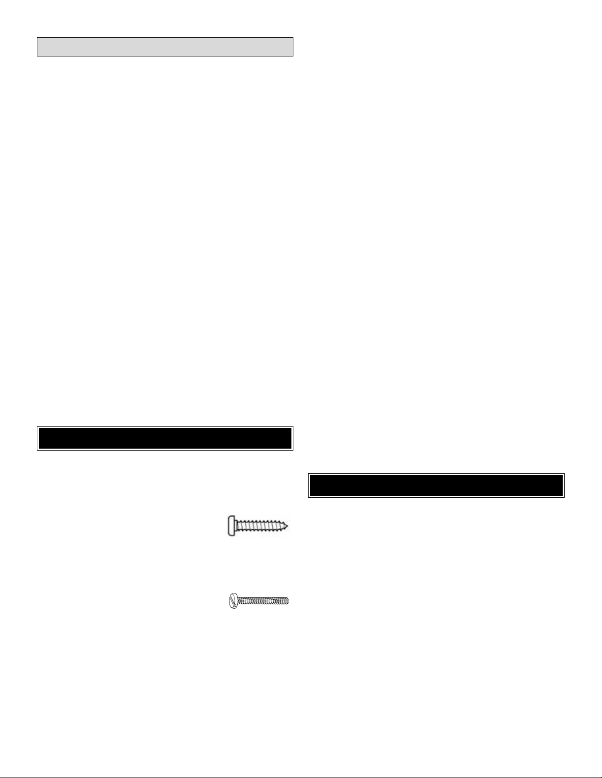
• There are two types of screws used in this kit:
Sheet metal screws are designated by a number and a
length. For example #6 x 3/4" [19mm]
This is a number six screw that is 3/4
"
[19mm] long.
Machine screws are designated by a number, threads per
inch and a length. For example 4-40 x 3/4" [19mm]
This is a number four screw that is 3/4"
[19mm] long with forty threads per inch
.
• When you see the term
test fit
in the instructions, it means
that you should first position the part on the assembly
without using any glue, then slightly modify or
custom fit
the part as necessar y for the best fit.
• Whenever the term
glue
is written you should rely upon
your experience to decide what type of glue to use.When
a specific type of adhesive works best for that step, the
instructions will make a recommendation.
• Whenever just
epoxy
is specified you may use
either
30minute (or 45-minute) epoxy or6-minute epoxy. When 30minute epoxy is specified it is highly recommended that
you use only 30-minute (or 45-minute) epo xy, because you
will need the working time and/or the additional strength.
• Photos and sketches are placed before the step they
refer to .Frequently you can study photos in following steps
to get another view of the same parts.
• The Minnow is factory-covered with Top Flite MonoKote
film. Should repairs ever be required, MonoKote can be
patched with additional MonoKote purchased separately.
MonoKote is packaged in six-foot rolls, but some hobby
shops also sell it by the foot. If only a small piece of
MonoKote is needed for a minor patch, perhaps a fellow
modeler would give you some. MonoKote is applied with a
model airplane covering iron, but in an emergency a
regular iron could be used. A roll of MonoKote includes full
instructions for application. Following are the colors used
on this model and order numbers for six foot rolls.
Dark Red TOPQ0218
Sapphire Blue TOPQ0226
White TOPQ0204
• The stabilizer and wing incidences and engine thrust
angles have been factory-built into this model. However,
some technically-minded modelers may wish to check
these measurements anyway.To vie w this inf ormation, visit
the web site at
www.greatplanes.com
and click on
“Technical Data.”Due to manufacturing tolerances that will
have little or no eff ect on the way your model will fly, please
expect slight deviations between your model and the
published values.
Fuse = Fuselage
Stab = Horizontal Stabilizer
Fin = Ver tical Fin
LE = Leading Edge
TE = Trailing Edge
LG = Landing Gear
Ply = Plywood
" = Inches
mm = Millimeters
SHCS = Socket Head Cap Screw
COMMON ABBREVIATIONS
IMPORTANT BUILDING NOTES
Optional Supplies and Tools
4
5
Before starting to build, take an inventory of this kit to make sure it is complete and inspect the parts to make sure they
are of acceptable quality. If any parts are missing or are not of acceptable quality , or if y ou need assistance with assemb ly,
contact Product Support. When repor ting defective or missing parts, use the part names exactly as they are written in
the Kit Contents list.
Great Planes Product Support:
3002 N Apollo Drive, Suite 1
Champaign, IL 61822
Telephone: (217) 398-8970, ext. 5
Fax: (217) 398-7721
E-mail:
airsupport@greatplanes.com
KIT INSPECTION
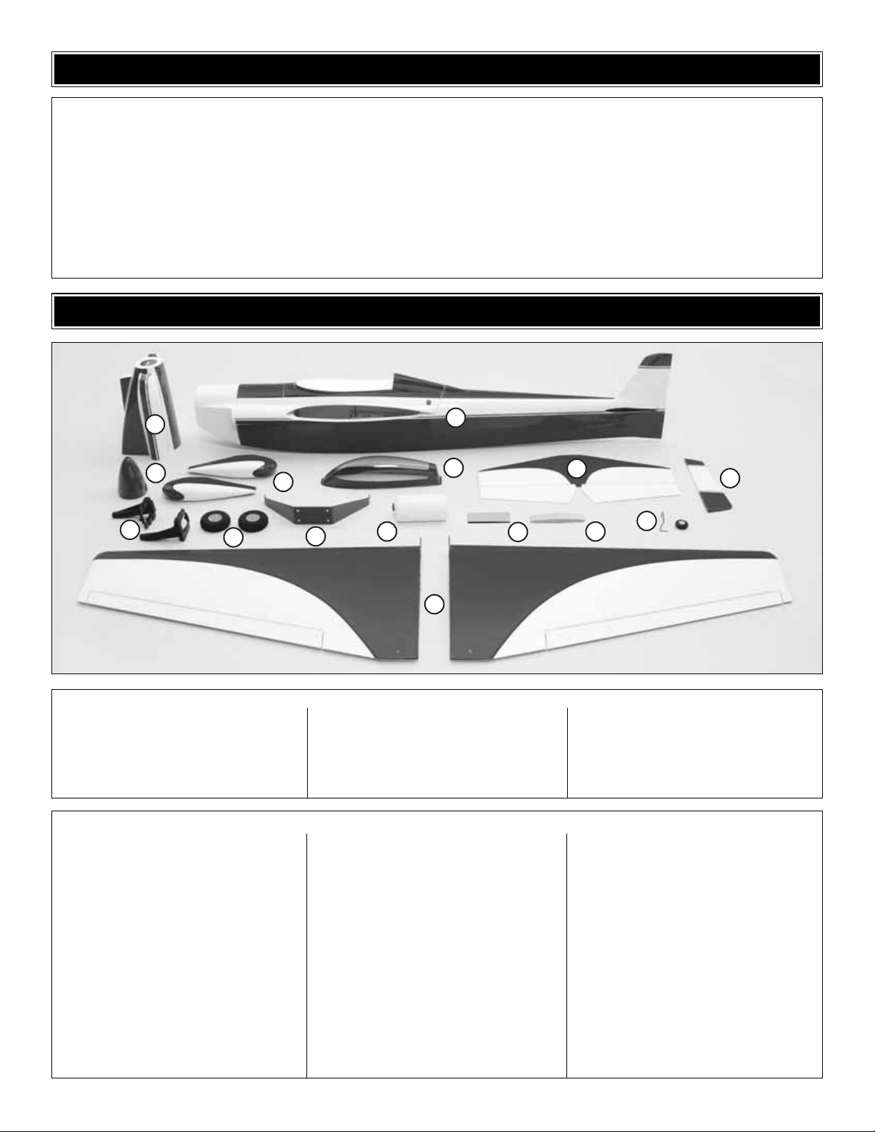
1 Wing
2 Fuselage with Canopy Base
3 Cowl
4 Spinner
5 Adjustable Engine Mount
6 Wheels
7 Wheel Pants
8 Main Landing Gear
9 Fuel Tank
10 Canopy
11 Stabilizer with Elevators
12 Rudder
13 Wing Bolt Plate
14 Wing Joiner
15 Tail Wheel Assembly
Kit Contents (Photographed)
5/32" x 2" Axle (2)
Brass Body EZ Connector (2)
4-40 Blind Nuts (4)
4-40 Nut (1)
8-32 Blind Nut (8)
5/16-24 Lock Nut (2)
1/4-20 Blind Nuts (2)
Large Nylon Control Horn (5)
Nylon Torque Rod Bearing (1)
1/4-20 Nylon Wing Bolt (2)
Nylon Clevis (5)
Nylon Retainer (2)
2" x 9" Hinge Material (1)
FasLink™(4)
Grey Plastic Outer Pushrod 24" (5)
Silicone Clevis Retainer (5)
2-56 x 5/8" Machine Screw (10)
6-32 x 1/8" Set Screw (2)
6-32 x 1/4"SHCS (4)
4-40 Set Screw (1)
#2 x 3/8" Sheet Metal Screw (12)
#4 x 3/8" Sheet Metal Screw (4)
4-40 x 1/2" Machine Screw (4)
#2 x 3/8" Wood Screw (4)
8-32 x 1-1/4" SHCS (4)
8-32 x 1" SHCS (4)
4-40 x 1/8" SHCS (2)
8-32 x 3/4" Flat Head Machine Screw (4)
3/32" Wheel Collar (1)
5/32" Wheel Collar (6)
1-1/4" Tail Wheel (1)
.074" Wire Threaded One End 36" (4)
.074" x 6" Pushrod Wire (2)
4-40 x 12" Threaded Wire (1)
#4 Lock Washer (4)
#4 Flat Washers (8)
#2 Flat Washers (12)
#8 Lock Washers (8)
#8 Flat Washers (8)
7-3/4" [200mm] Velcro
®
Kit Contents (Not Photographed)
KIT CONTENTS
3
4
5
6
2
7
8
9
10
1
13
11
14
15
12
6
ORDERING REPLACEMENT PARTS
Replacement parts for the Great Planes Minnow ARF are available using the order numbers in the Replacement Parts
List that follows.The fastest, most economical service can be provided by your hobby dealer or mail-order company.
To locate a hobby dealer, visit the Hobbico web site at www.hobbico.com.Choose “Where to Buy” at the bottom of the menu
on the left side of the page. Follow the instructions provided on the page to locate a U.S., Canadian or International dealer.
If a hobby shop is not available, replacement parts may also be ordered from Tower Hobbies at www.towerhobbies.com,
or by calling toll free (800) 637-6050.
Parts may also be ordered directly from Hobby Services by calling (217) 398-0007, or via facsimile at (217) 398-7721, but
full retail prices and shipping and handling charges will apply. Illinois and Nevada residents will also be charged sales tax.
If ordering via fax, include a Visa or MasterCard number and expiration date for payment.
Mail parts orders and payments by personal check to:
Hobby Services
3002 N Apollo Drive, Suite 1
Champaign IL 61822
Be certain to specify the order number exactly as listed in the Replacement Parts List.Payment by credit card or personal
check only; no C.O.D.
If additional assistance is required for any reason contact Product Support by e-mail at productsupport@greatplanes.com
or by telephone at (217) 398-8970.
Replacement Parts List
Or
der Number
Description How to Pur
chase
Missing pieces ................................................Contact Product Support
Instruction manual...........................................Contact Product Support
Full-size plans.................................................Not available
Kit parts listed below .......................................Hobby Supplier
GPMA2491............Wing Kit
GPMA2490............Fuse Kit
GPMA2492............Tail Set
GPMA2493............Cowl
GPMA2496............Canopy
GPMA2494............Landing Gear
GPMA2495............Wheel Pants
GPMA2497............Top Wing Cover Only
IMPORTANT INFORMATION ABOUT WORKING WITH FIBERGLASS
If you have never w orked with fiberglass there are a few
basic things you should be aware of:
1. When cutting fiberglass, be sure you are cutting the
correct place. Unlike wood, you are not able to go back and
easily fix a mistake.
2.Whenever you are gluing a part to the inside of fiberglass
it is important to roughen the inside surface of the fiberglass
with 220-grit sandpaper, then wipe the area with rubbing
alcohol. The molding process leaves a waxy residue that
can prevent a good bond between the glue and the parts
being glued.
3. If you do not have a high-speed motor tool such as a
Dremel tool you should consider purchasing one or
borrowing one from a fellow modeler. This, combined with a
fiberglass cut-off wheel will be extremely helpful in the
assembly process.
WARNING:The cowl, wheel pants and fuselage included in
this kit are made of fiberglass, the fibers of which may cause
eye, skin and respiratory tract irritation. Never blow into a
part to remove fiberglass dust, as the dust will blow back
into your eyes. Always wear safety goggles, a particle mask
and rubber gloves when grinding, drilling and sanding
fiberglass parts. Vacuum the parts and the work area
thoroughly after working with fiberglass parts.
❏ 1. If you have not done so already, remove the major
parts of the kit from the box and inspect for damage. If any
parts are damaged or missing, contact Product Suppor t at
the address or telephone number listed in the “Kit
Inspection” section on page 5.
❏ 2.Remove the tape and separate the ailerons from the wing
and the elevators from the stab. Use a covering iron with a
covering sock on high heat to tighten the cov ering if necessary .
Apply pressure over sheeted areas to thoroughl y bond the
covering to the wood.
Do the right wing first so your work matc hes the photos
the first time through.You can do one wing at a time, or
work on them together.
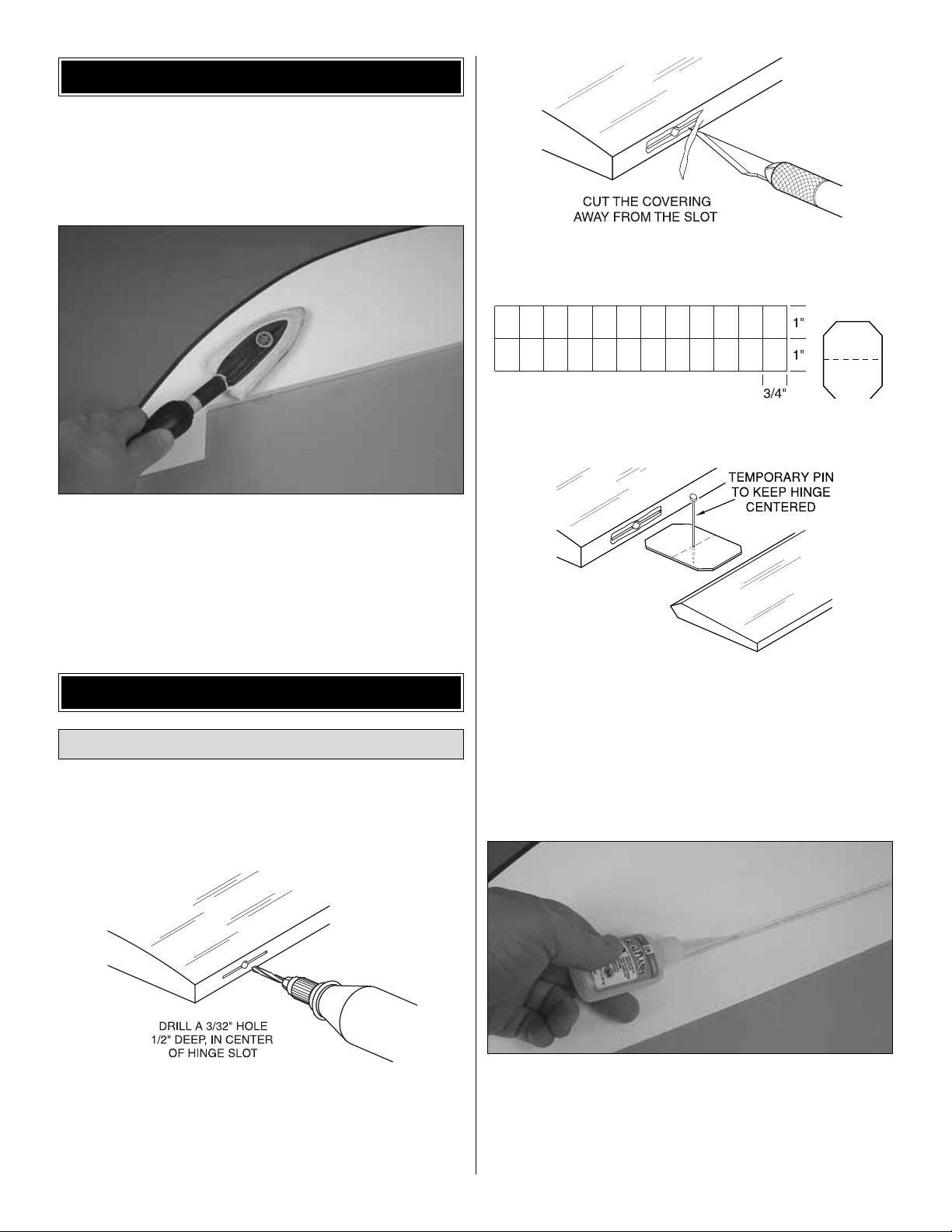
❏❏1. Drill a 3/32" [2.4mm] hole, 1/2" [13mm] deep in the
center of each hinge slot to allow the CA to “wick”in. Followup with a #11 blade to clean out the slots. Hint: If you have
one, use a high-speed rotary tool to drill the holes.
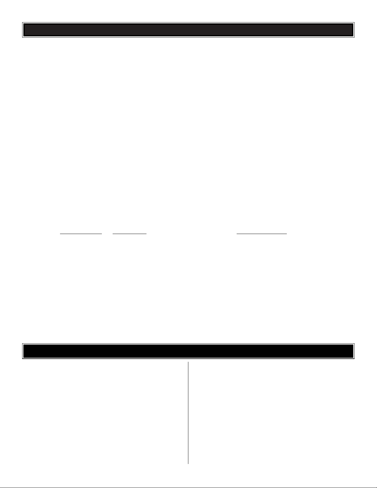
❏❏2.Use a sharp #11 blade to cut a strip of covering from
the hinge slots in the wing and aileron.
❏❏3.Cut eight 3/4" x 1" [19 x 25mm] hinges from the CA
hinge strip.Snip off the corners so they are easier to insert.
❏❏4. Test fit the ailerons to the wing with the hinges. If
the hinges don’t remain centered, stick a pin through the
middle of the hinge to hold it in position.
❏❏5. Remove any pins you may have inserted into the
hinges.Adjust the aileron so there is a small gap between the
LE of the aileron and the wing.The gap should be small, just
enough to see light through or to slip a piece of paper through.
❏❏6. Apply six drops of thin CA to the top and bottom of
each hinge waiting a few seconds between drops to allow
the CA to soak in. Do not use CA accelerator. After the CA
has fully hardened, test the hinges by pulling on the aileron.
❏ 7. Repeat steps 1- 6 for the left wing panel.
Install the Ailerons
ASSEMBLE THE WING
PREPARATIONS
7
❏❏1. Installing the servos in the wing will require the use
of one 6" [152mm] servo extension for each aileron. One
Y-harness connector is required and is used to allow the aileron
servos to plug into one slot in your receiver.You may have a
computer radio that allows you to plug the servos into separate
slots and mix them together through the radio transmitter .If you
choose to mix them with the radio rather than the Y-harness,
refer to the instructions with your particular brand of radio.
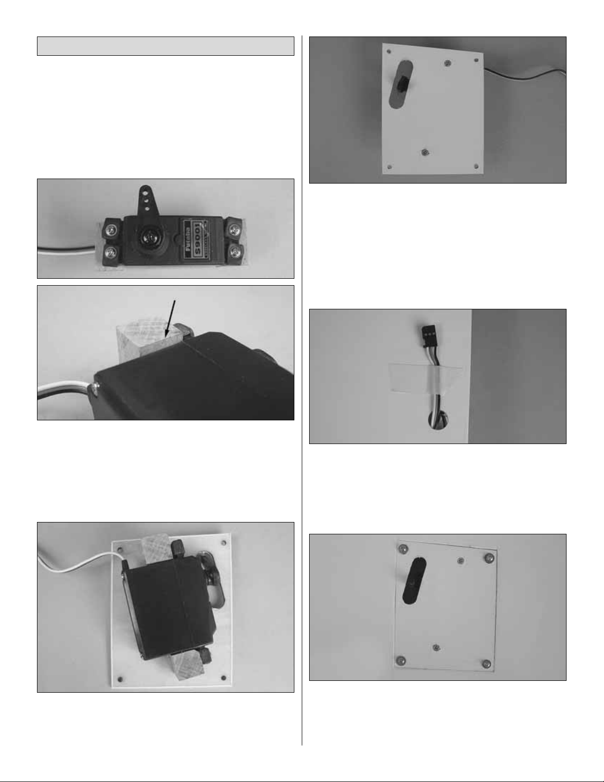
❏❏2.Remove the tape holding the servo cover to the wing.
Locate two 1/2" x 1/2" x 3/4" [12 x 12 x 20mm] hardwood
blocks. Place the blocks against the sides of your aileron
servo. When positioning the blocks they should be slightly
higher than the servo case.Drill a 1/16" [1.6mm] hole through
the blocks for the servo screws.Using the hardware included
with your radio system screw the servos to the two blocks.
❏❏3. Apply 6-minute epoxy to each block. Position the
blocks so that the servo arm is centered over the opening in
the cover.Clamp the blocks to the cover.When the glue has
hardened, remove the clamps.
❏❏4. Mark the center of the hardwood blocks on the
cover. Drill a 1/16" [1.6mm] hole through the marks, drilling
through the blocks.Install a #2 x 3/8" [9mm] wood screw into
each of the holes tightening them against the cover.
❏❏5. Attach the servo extension to the aileron servo.
Secure the connectors together using a large piece of heat
shrink tubing, tape or other method for securing the
connectors together.
❏❏6. Located in the wing in the servo compar tment, a
string is taped to the wing skin. Tie the string to the end of
the servo wire. Pull the servo wire through the wing with the
string. Feed the servo wire out the hole in the bottom of the
wing center section. Tape the servo wire to the wing to
prevent it from falling back into the wing.
❏❏7. Center the servo. Trial fit the servo cover into the
wing. Depending on the size and mounting position of your
particular servo you may need to trim away some of the
wood edge the cover rests on.Tr im as needed to allow the
servo cover to be positioned properly on the wing.
Install the Aileron Servos and Pushrods
8
❏❏8. Place the cover on the wing. Drill a 1/16" [1.6mm]
hole through each of the pre-drilled mounting holes. Remove
the cover from the wing.Install and remove a #2 x 3/8" [9mm]
sheet metal screw into each of the four holes.Insert a drop of
thin CA into the holes to harden the wood. After the glue has
hardened, install the cover with four #2 x 3/8" [9mm] sheet
metal screws and four #2 flat washers.
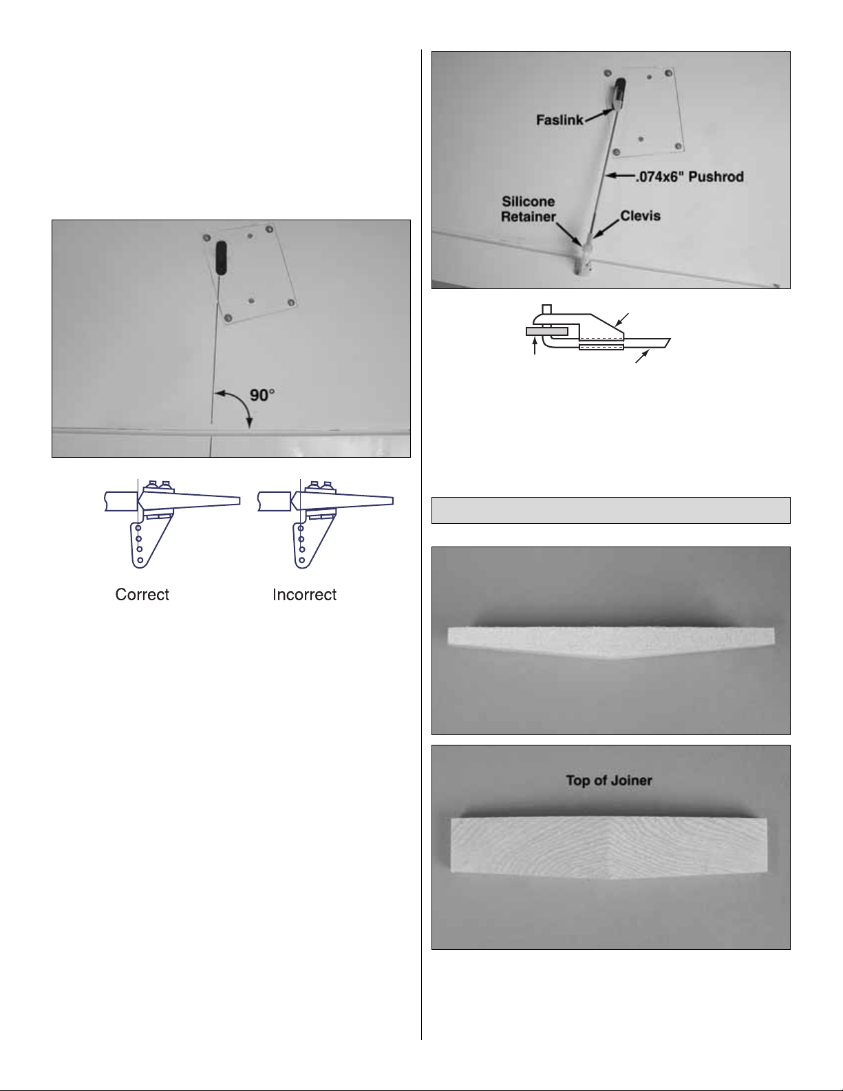
❏❏9. Position a nylon control horn on the aileron,
positioning it as shown in the sketch and aligning it with the
servo arm. Mark the location for the screw holes. Drill
through the marks you made with a 1/16" [1.6mm] drill bit,
drilling through the aileron. Secure the control hor n to the
aileron with two 2-56 x 5/8" [16mm] machine screws and the
nylon mounting plate.
❏❏10. Locate a .074" x 6" [.074" x 152mm] pushrod wire
threaded on one end. Screw a nylon clevis onto the
threaded end of the wire 20 full turns. Install a silicone clevis
keeper onto the clevis, then install the clevis in the second
hole from the end of the aileron control horn.
❏❏11. Be sure the aileron servo is centered. Enlarge the
first hole in the servo arm with a Hobbico Servo Horn Drill
(or a #48 or 5/64" [2mm] drill bit). Center the aileron and
align the wire pushrod with the hole in the end of the servo
arm.Using a marker, mark the location where the wire aligns
with the hole in the servo arm. On that mark make a 90
degree bend. From the bend measure an additional 3/16"
[4.8mm] then cut off the excess pushrod wire.
❏❏12.Install the wire into the hole in the servo arm using
a nylon FasLink as shown in the sketch.
❏ 13. Repeat steps 1-12 for the left wing panel
❏ 1. Locate the hardwood wing joiner. Notice that the
joiner is cut with a double taper. Test fit the joiner into both
wing halves to see exactly how it fits into the wing, making
sure that it is not too tight. Sand the joiner as needed to get
a good fit.
Join the Wings
9
Faslink
Servo Horn
2-56(.074") Pushrod Wire
 Loading...