

Page 1
WARRANTY
Great Planes
®
Model Manufacturing Co. guarantees this kit to be free from defects in both material and workmanship at the date of
purchase. This warranty does not cover any component parts damaged by use or modification. In no case shall Great Planes’
liability exceed the original cost of the purchased kit. Further, Great Planes reserves the right to change or modify this warranty
without notice.
In that Great Planes has no control over the final assembly or material used for final assembly, no liability shall be assumed nor
accepted for any damage resulting from the use by the user of the final user-assembled product. By the act of using the
user-assembled product, the user accepts all resulting liability.
If the buyer is not prepared to accept the liability associated with the use of this product, the buyer is advised to return this
kit immediately in new and unused condition to the place of purchase.
While this kit has been flight tested to exceed normal use, if the plane will be used for extremely high stress flying, the modeler is
responsible for taking steps to reinforce the high stress points.
READ THROUGH THIS MANUAL BEFORE
STARTING CONSTRUCTION. IT CONTAINS
IMPORTANT WARNINGS AND INSTRUCTIONS
CONCERNING THE ASSEMBLY AND USE OF
THIS MODEL.
GPMZ0217 for GPMA1315 V1.0© Copyright 2000
P.O. Box 788 Urbana, IL 61803 (217) 398-8970
INSTRUCTION MANUAL
Page 2

Important Safety Precaution......................................................2
Introduction.................................................................................2
Precautions .................................................................................2
Decisions You Must Make..........................................................3
Engine Selection....................................................................3
Preparations................................................................................3
Required Accessories............................................................3
Building Supplies and Tools ..................................................3
Optional Supplies and Tools ..................................................4
General Inspection ................................................................4
Inch/Metric Ruler ...................................................................4
Parts List................................................................................5
Wing Assembly ...........................................................................6
Rudder Assembly ..................................................................6
Wing Installation .........................................................................7
Install The Stabilizer...................................................................7
Engine Installation......................................................................8
Cowling Installation..................................................................10
Fuel Tank Installation ...............................................................10
Main Landing Gear Installation ...............................................11
Radio Installation......................................................................12
Attach the Ailerons...............................................................12
Install the Aileron Servos.....................................................13
Attach the Elevators ............................................................14
Install the Elevator Servos...................................................15
Attach the Rudder................................................................16
Install the Rudder Servo......................................................16
Tail Gear Installation ............................................................17
Throttle Servo Installation....................................................18
Receiver & Battery Installation ............................................19
Final Assembly..........................................................................19
Control Throw Adjustment ...................................................20
Control Surface Throws.......................................................20
Balance Your Model..................................................................20
Balance Your Model Laterally ..............................................21
Advanced Aerobatics ...............................................................21
Preflight .....................................................................................23
Charge the Batteries ...........................................................23
Balance the Propeller ..........................................................23
Find a Safe Place to Fly ......................................................23
Ground Check Your Model ..................................................23
Range Check Your Radio ....................................................23
Engine Safety Precautions ..................................................24
AMA Safety Code (excerpt)......................................................24
General................................................................................24
Radio Control.......................................................................24
Flying .........................................................................................24
Takeoff .................................................................................24
Flying ...................................................................................25
Landing................................................................................25
Appendix: Flight Trimming......................................................26
Flight Log ..................................................................Back Cover
Engine Mount Template ...........................................Back Cover
Your Giles G-202 ARF is not a toy, but rather a
sophisticated, working model that functions very much like a
full-size airplane. Because of its realistic performance, the
Giles G-202 ARF, if not assembled and operated correctly,
could possibly cause injury to yourself or spectators and
damage property.
To make your R/C modeling experience totally enjoyable,
we recommend that you get experienced, knowledgeable
help from an instructor with assembly and during your first
flights. You’ll learn faster and avoid risking your model
before you’re truly ready to solo. Your local hobby shop has
information about flying clubs in your area whose
membership includes qualified instructors.
You can also contact the national Academy of Model
Aeronautics (AMA), which has more than 2,500 chartered
clubs across the country. Through any one of them,
instructor training programs and insured newcomer training
are available. Contact the AMA at the address or toll-free
phone number below:
Academy of Model Aeronautics
5151 East Memorial Drive
Muncie, IN 47302-9252
Tele. (800) 435-9262
Fax (765) 741-0057
Or via the internet at: http://www.modelaircraft.org
Congratulations and thank you for purchasing the Great
Planes Giles G-202 ARF. We’d like to provide you with a bit
of history on our selection of this aircraft as the newest
release in the Great Planes scale aerobatic ARF line.
Richard Giles noted a trend in the International Aerobatic
Club (I.A.C.) competition arena toward bigger, heavier, more
costly “super monoplanes,” and he wanted to do better. The
resulting “full-scale” Giles G-200 and G-202 were designed
specifically to be a reasonably priced, low wing loading,
unlimited level, superior performer on a reasonably priced
4-cylinder engine.
Flying the Giles G-202 is a thrilling experience–as it should
be for such an aerobatic model! It doesn’t take much
elevator or aileron throw to put the Giles through its paces.
When you have a feel for your Giles G-202, the throws can
be increased to high rates (illustrated in the instructions) to
really showcase the aerobatic potential.
We hope you enjoy building and flying your Great Planes
Giles G-202 ARF as much as we did testing the prototypes.
1. You must assemble the model according to the
instructions. Do not alter or modify the model, as doing so
may result in an unsafe or unflyable model.
2. Take time to align the components straight, true and
strong.
PRECAUTIONS
INTRODUCTION
PROTECT YOUR MODEL,YOURSELF &
OTHERS...FOLLOW THIS IMPORTANT
SAFETY PRECAUTION
TABLE OF CONTENTS
2
Page 3

3. Use an R/C radio system that is in first-class condition,
and a correctly sized engine and components (fuel tank,
wheels, etc.) throughout your assembly process.
4. You must properly install the R/C radio system and other
components so that the model operates properly on the
ground and in the air.
5. You must test the operation of the model before every
flight to insure that all equipment is operating and you must
make certain that the model has remained structurally
sound. Be sure to check clevises and other connectors often
and replace them if they show signs of wear or fatigue.
Remember: Take your time and follow directions to end up
with a well-built model that is straight and true. Please
inspect all parts carefully before starting to build! If any parts
are missing, broken or defective, or if you have any
questions about assembling or flying this airplane, please
call us at (217) 398-8970. If you are calling for replacement
parts, please reference the part names and numbers on
page 5 and have them ready when calling.
We can also be reached by e-mail at:
productsupport@greatplanes.com
Items in parentheses such as (GPMQ4243) are suggested
part numbers recognized by distributors and hobby shops
and are listed for your ordering convenience. GPM is the
Great Planes brand, TOP is the Top Flite®brand, and HCA
is the Hobbico®brand.
❏ Four-Channel Radio with Six Servos (minimum of 65
oz/in of torque for flight controls)
❏ “Y” Harness for Aileron and Elevator Servos (if not
using a computer radio)
❏ Five 24" Servo Extensions for Aileron, Elevator and
Rudder Servos
❏ Engine - See Engine Selection
❏ Spare Glow Plugs (O.S. #8 for most 2-Stroke engines,
OSMG2691, or O.S. Type F for most 4-stroke engines,
OSMG2692)
❏ Propeller (Top Flite Power Point
®
-refer to your engine’s
instructions for proper size)
❏ 3' Medium 3/32" Glow Fuel Tubing (GPMQ4131)
❏ 1/4" Latex Foam Rubber Padding (HCAQ1000)
These are the building tools that are required. We
recommend Great Planes Pro™CA and Epoxy glue.
❏ 2 oz. Pro CA (Thin, GPMR6003)
❏ 2 oz. Pro CA+ (Medium, GPMR6009)
❏ CA Accelerator (GPMR6035)
❏ 6-Minute Pro Epoxy (GPMR6045)
❏ 30-Minute Pro Epoxy (GPMR6047)
❏ Canopy Glue (JOZR5007)
❏ #1 Hobby Knife Handle (HCAR0105)
❏ #11 Blades (HCAR0311, 100 Qty)
❏ Builders Triangle Set (HCAR0480)
❏ Masking Tape (TOPR8018)
❏ Electric Power Drill
❏ Slip-Joint & Needle Nose Pliers
❏ Monofilament String for Stabilizer Alignment
❏ Screwdrivers – Flat Blade & Phillips
❏ Pro Thread Locking Compound (GPMR6060)
❏ Isopropyl Alcohol (70%)
❏ Drill Bits: 1/16" [1.5mm], 3/32" [2.5mm], 1/8" [3mm],
9/64"[3.5mm], 3/16" [5mm], 7/32" [5.5mm], 1/4"
[6mm],
5/16" [8mm], 1/2" [13mm], #29
❏ 8-32 Tap & Drill (GPMR8103)
❏ Top Flite Trim Seal Tool
™
(TOPR2200)
❏ Panel Line Pen (TOPQ2510)
❏ Sandpaper (coarse and fine grit)
❏ Metal File
❏ 3/4 oz. Fiberglass Cloth (HCAR5000)
❏ Paper Towels
❏ T-Pins (HCAR5100)
❏ Silver Solder (GPMR8070)
Building Supplies & Tools
Required Accessories
PREPARATIONS
Engine Selection
There are several engines that will work well in your Giles
G-202 ARF. We recommend a SuperTigre®G-2300 for the
best performance for your Giles G-202. An O.S.®FT-160
would be the best choice for a 4-stroke. Your choice of
2-stroke or 4-stroke will determine the location of the
throttle servo and throttle pushrod exit on the firewall, so
plan ahead.
Note: Please see the FLYING section regarding flutter,
propeller selection and aerobatic performance.
DECISIONS YOU MUST MAKE
Note: We, as the manufacturer, provide you with a
top quality kit and great instructions, but ultimately
the quality of your finished model depends on how
you assemble it; therefore, we cannot in any way
guarantee the performance of your completed
model, and no representations are expressed or
implied as to the performance or safety of your
completed model.
3
Page 4

❏ Electrical Tape or Heat Shrink Tubing
❏ Hobby Heat
™
Micro Torch (HCAR0750)
❏ Razor Saw
❏ Petroleum Jelly
❏ 4" White Spinner
❏ CA Applicator Tips (HCAR3780)
❏ Epoxy Brushes (GPMR8060)
❏ Epoxy Mixing Sticks (GPMR8055, Qty. 50)
❏ CA Debonder (GPMR6039)
❏ Dremel
®
Moto-Tool™or Similar with Cut-Off Wheel
❏ Hot Sock
™
(TOPR2175)
❏ Dead Center
™
Engine Mount Hole Locator
(GPMR8130)
❏ Curved Tip Canopy Scissors for Canopy Trimming
(HCAR0667)
❏ Switch and Charge Jack (GPMM1000)
❏ Sealing Iron (TOPR2100)
❏ Household Oil
❏ 6 oz. Segmented Lead Weight (GPMQ4485)
❏ C.G. Machine
™
(GPMR2400)
❏ Power Point
®
Balancer (TOPQ5700)
❏ Fingertip Prop Balancer (GPMQ5000)
❏ Fueling System (Great Planes Top Fueler
™
,
GPMQ4160)
1. Closely inspect the fuselage, wing panels, rudder
assembly and stabilizer assembly for damage. If you find
any damage, contact the place of purchase, or Hobby
Services at Great Planes for a replacement.
2. Eliminate any wrinkles you find in the covering by
shrinking them away with a heat gun, then apply pressure to
the area with a covering iron and a hot sock. This will
securely bond the covering to the wood so the wrinkles will
be less likely to reappear in the future. Caution: Be careful
while working around areas where the colors overlap.
General Inspection
Optional Supplies & Tools
4
Inch Scale
0" 1" 2" 3" 4" 5" 6" 7"
0 10 20 30 40 50 60 70 80 90 100 110 120 130 140 150 160 170 180
Metric Scale
Page 5
5
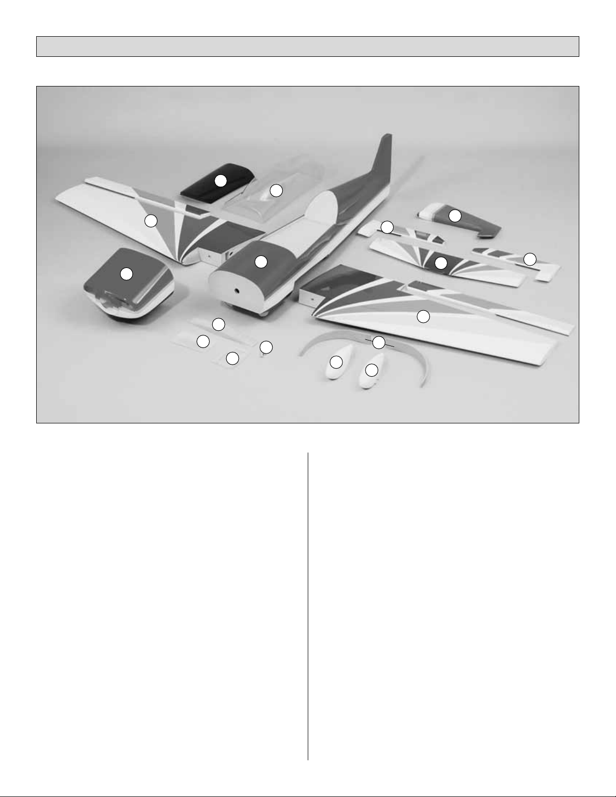
Key# Description Qty
1
Fuselage 1
2 Left Wing Panel w/Aileron 1
3 Right Wing Panel w/Aileron 1
4 Cowl 1
5 Wing Belly Pan 1
6 Canopy 1
7 Right Wheel Pant 1
8 Left Wheel Pant 1
9 Aluminum Landing Gear (Right & Left) 2
10 Stabilizer 1
11 Elevator Assembly (Right & Left) 2
12
Rudder 1
13 Wing Dowels 2
14 Servo Tray 1
15 Wing Joiner 1
16 Wing Bolt Plate 1
Parts Not Shown In Photo
Description Qty
Adjustable Engine Mount (Right & Left Halves)
2
Tail Wheel Assembly 1
Main Wheels 2
CA Hinge Strip (2" x 9") 1
Hardware Bag 1
Replacement Parts
If needed, replacement parts for
Giles G-202 ARF
are
available through your hobby supplier.
Wing Set............................................................GPMA2180
Fuselage Kit ......................................................GPMA2181
Tail Set...............................................................GPMA2182
Canopy ..............................................................GPMA2183
Cowl ..................................................................GPMA2184
Wheel Pants ......................................................GPMA2185
Landing Gear Set ..............................................GPMA2186
Parts List
11
11
10
12
6
5
2
3
1
4
13
7
8
14
15
16
9
Page 6
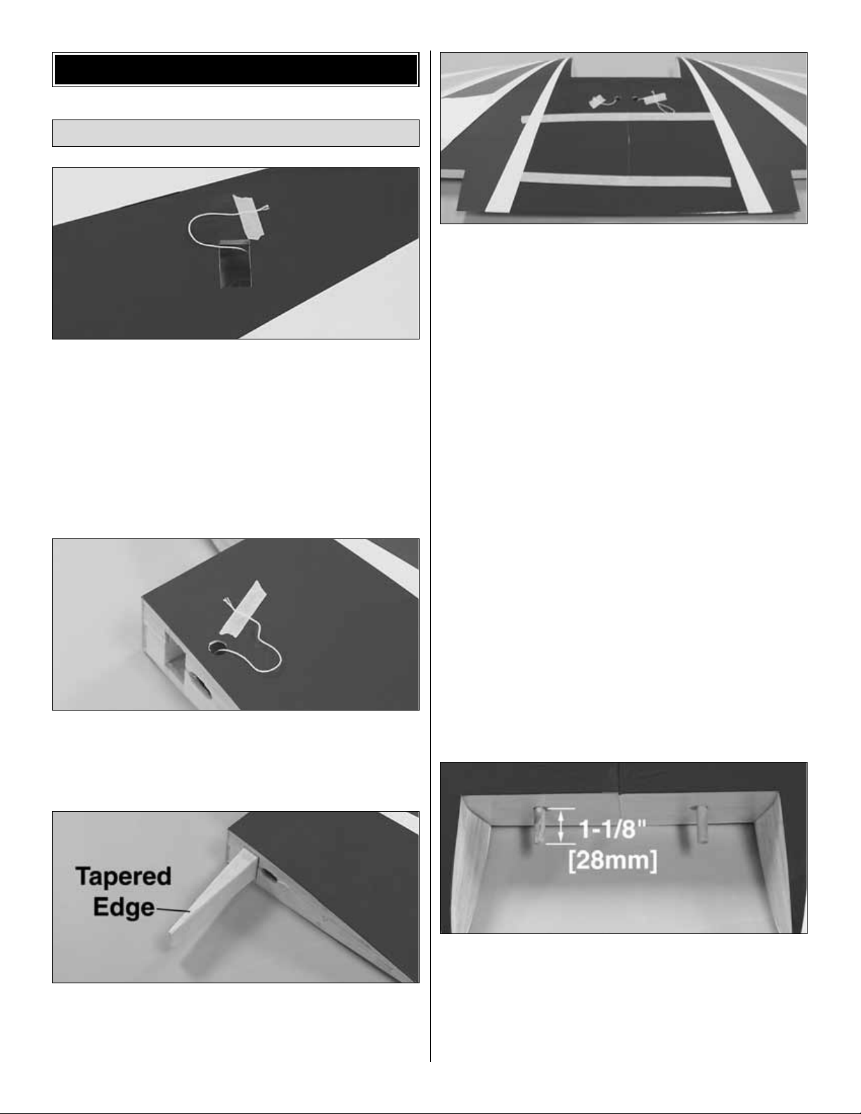
❏❏ 1. Locate the servo cut out on the bottom of each wing
and cut the covering 1/8" [3mm] inside the edges of the
opening in the bottom of the right wing panel for the aileron
servo. Use your Top Flite MonoKote®Trim Seal Tool™to seal
the covering to the sides of the opening.
Note: You’ll notice a piece of string that passes through the
ribs at the location of the aileron servo well. Don’t remove
the string because you will use it to pull your aileron servo
cord through the wing later. Tape the string in place as
shown.
❏❏ 2. Locate the hole and cut the covering on the top of
the right wing panel for the string to exit. Remove the tape
from the wing root, and route it through the opening. Tape
the string to the top of the wing.
❏❏ 3. Test fit the wing halves with the wing joiner. The
tapered edge of the joiner faces the leading edge of the
wing. If necessary, sand any high spots on the root end of
the wing panels so there is no gap when you join them.
❏ 4. Tape a piece of wax paper or Great Planes Plan
Protector™over your work surface. Thoroughly coat the
joiner pockets and the mating ends of both wing halves with
30-minute epoxy. Set the wing halves aside and proceed
quickly. Coat all surfaces of one half of the wing joiner with
30-minute epoxy and place it in one of the wing halves. Coat
the other half of the joiner with 30-minute epoxy and join the
other wing. Use a piece of balsa or cardboard to wipe away
excess epoxy. Use masking tape to tape the wing tightly
together. Use a paper towel dampened with alcohol to wipe
away any more epoxy that oozes out of the wing, then set
the wing aside. Do not disturb the wing until the epoxy has
fully cured.
❏ 5. Locate the two 5/16" x 3-3/8" [8mm x 86mm]
hardwood wing dowels. Slightly bevel the ends of the
dowels. Test fit the dowels into the wing, making sure they
lock into the holes inside the wing. If necessary, drill the
holes in the wing using a 5/16" [8mm] drill bit. Use 30-
minute
epoxy to glue the dowels into the wing, allowing them to
protrude 1-1/8" [28mm].
Rudder Assembly
WING ASSEMBLY
6
Page 7
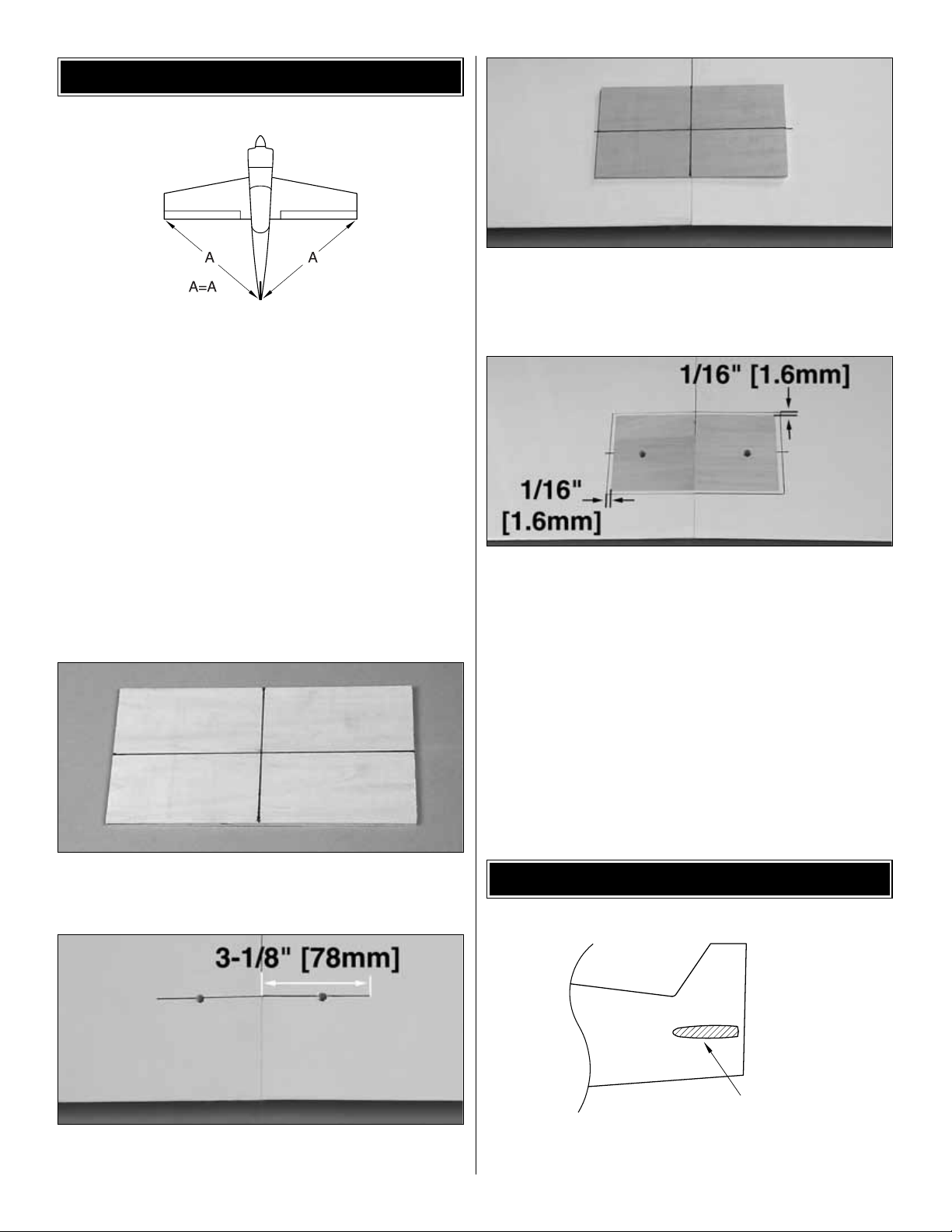
❏ 1. Place the wing on the fuselage. Measure from the aft
center of the fuselage to one wing tip and record the
distance. Measure from the same point to the opposite wing
tip, and compare it to the first measurement. If the
measurements are not the same, adjust the wing and
re-measure until they are equal. Place a mark on the wing
and fuselage so it can be repositioned accurately for the
following steps.
❏ 2. Remove the covering from the holes in the wing
center-section where the wing bolts will pass through the
wing as shown in the photo for step 5.
❏ 3. Bolt the wing to the fuselage using the 1/4-20 x 2"
nylon bolts. Enlarge the holes if necessary to allow the
bolts to pass through the wing. Check the alignment of the
wing and enlarge the holes in the wing if necessary to allow
the wing to be shifted to match the alignment marks.
❏ 4. Locate the 1/8" x 6" x 3-1/8" [3mm x 150mm x 78mm]
plywood wing bolt plate. Draw a vertical and horizontal
centerline onto the plate as shown in the photo.
❏ 5. Draw a line 3-1/8" [78mm] to each side of the center of
the wing through the center of the bolt holes.
❏ 6. Position the wing bolt plate onto the bottom of the
wing.
Align the vertical and horizontal centerlines on the plate with
the center of the wing and the line drawn through the center
of the bolts. Trace around the plate using a felt-tip marker.
❏ 7. Use a fresh #11 blade to carefully cut through the
covering 1/16" [1.5mm] inside the lines. Do not cut the
wood under the covering! This will weaken the structure
and may cause failure in flight. Remove the covering from
the wing within the lines you cut. Use medium CA to glue the
plate to the wing. Drill the holes for the bolts in the plate from
the top of the wing.
❏ 1. Remove the covering from the fuselage sides in the
location for the horizontal stabilizer.
Remove Covering
INSTALL THE STABILIZER
WING INSTALLATION
7
Page 8
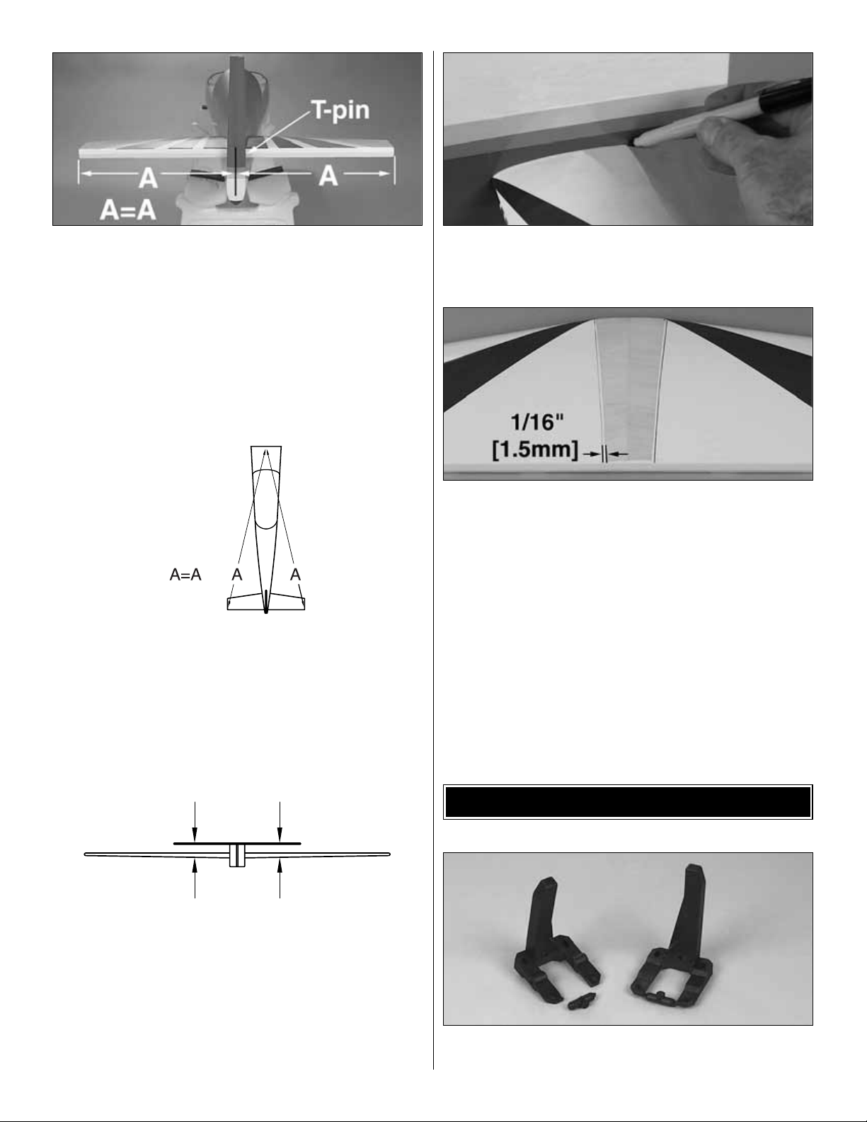
❏ 2. Slide the stabilizer into the fuselage. Center the
stabilizer
in the fuselage by measuring the distance from the
fuselage
to the tip of the stabilizer. The stabilizer is centered when the
measurements from both sides are equal. Place a T-pin into
the stabilizer against the fuselage on one side to allow the
stabilizer to be repositioned if it accidentally moves.
❏ 3. Perform the same technique for aligning the stab as
was used for aligning the wing. This time, the center on the
fuselage is at the front, rather than the rear. Mark the stab
so it can be returned to its aligned location.
❏ 4. Mount the wing to the fuselage using the nylon bolts.
Stand back 8 to 10 feet [2.5 to 3 meters] and view the model
from the front and rear. The stab tips should be equally
spaced above the level of the wing. If not, lightly sand the
high side of the stab saddle to correct the problem. Work
slowly and check the alignment often.
❏ 5. Use a felt-tip pen to mark the sides of the fuselage on
the bottom and top of the stab. Remove the stab from the
fuselage.
❏ 6. Use a fresh #11 blade to carefully cut through the
covering 1/16" [1.5mm] inside the lines you marked on the
bottom and top of the stab that indicate the fuse sides. Do
not cut the wood under the covering! This will weaken
the structure and may cause the stab to fail in flight.
Remove the covering from the center of the stab within the
lines you cut.
❏ 7. Use a liberal coating of 30-minute epoxy to glue the
stab in position. Hold the stab in position with weights while
the epoxy cures. Double check the alignment with the wing
and fuse while the epoxy cures.
IMPORTANT: Form a thin epoxy fillet along the fuse sides
where the epoxy squeezes out to create a fuelproof seal
between the stab and fuselage.
❏ 1. Cut or break the “spreader bar” from each engine
mount half. Carefully trim any extra material left by the
ENGINE INSTALLATION
AA
A=A
8
Page 9
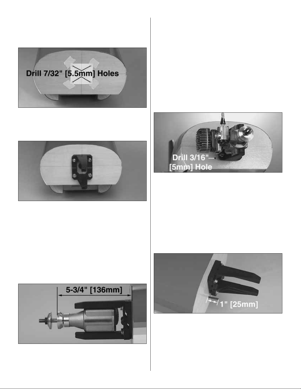
spreader bar from each mount half. The surfaces where the
spreader bars were attached must be smooth to allow the
mount halves to fit together. Trim the flashing off any rough
edges if necessary.
❏ 2. Copy the engine mount template from the back page
and tape it to the firewall as shown. At the locations on the
template, drill four 7/32" [5.5mm] holes in the firewall for the
engine mount blind nuts.
❏ 3. Install four 8-32 blind nuts to the inside of the firewall.
Pull the blind nuts into the back side of the firewall using
8-32 socket head cap screws with a flat washer under the
head of each screw. Fit the two halves of the Engine Mount
together. Use four #8 flat washers and four 8-32 x 1"
socket head cap screws to secure the engine mount to the
firewall. Do not tighten the screws at this time, as the mount
must be adjusted for the engine.
❏ 4. Test fit your engine into the mount. Adjust the width of
the rails to fit the engine snugly. Tighten the mount screws
to allow marking the engine mounting holes without moving
the rails.
❏ 5. Position the engine on the engine mount rails so the
propeller thrust washer is 5-3/4" [136mm] ahead of the
firewall. Use a Great Planes Dead Center Hole Locator
(GPMR8130) (not included) or a sharpened piece of wire to
scribe the four engine mount holes onto the rails. Use a
center punch at the marks to prevent the drill bit from
wandering, then drill #29 pilot holes through the rails. Be
sure to hold the drill perpendicular to the rails. If you have
access to a drill press, this is a good tool for this purpose.
Use an 8-32 tap to tap the holes for the 8-32 screws. Use
four 8-32 x 1" socket head cap screws to secure the engine
to the mount.
❏ 6. Drill a 3/16" [5mm] hole in the firewall for the throttle
pushrod. The hole location will depend on whether you are
installing a 2-stroke or 4-stroke engine.
❏ 7. Roughen the outside surface of the 36" [910mm]
throttle pushrod tube with coarse grit sandpaper. Insert
the pushrod tube through the hole in the firewall. Push it in
until it protrudes 1" [25mm] in front of the firewall. Use
medium CA to glue the tube to the firewall, but leave it free
inside the fuselage until the servos are installed.
Note: The engine has been removed from the above picture
for clarity.
9
Page 10

❏ 1. Use thin cardboard or plastic to make templates
locating the firewall and forward fuselage.
❏ 2. Slide the cowl over the engine and fuselage. Install the
spinner backplate and center the cowl 3/32" to 1/8" [2.5mm
to 3mm] behind the spinner backplate. Tape the cowl in
position and place four marks (two on each side of the cowl)
for the cowl mounting screws using the templates.
❏ 3. Drill a 3/32" [2.5mm] hole through the cowl and fuse at
each mark. Remove the cowl and enlarge the holes in the
cowl only to 1/8" [3mm]. With the cowl removed, apply a
couple of drops of thin CA to the cowl mounting holes in the
fuse to harden the wood. This will prevent the holes from
stripping out during flight. After the CA has cured, attach the
cowl to the fuse with four #4 washers and four #4 x 5/8"
sheet metal screws.
❏ 4. Remove the cowl and use a piece of thin cardboard or
plastic to make templates for the cutout in the cowl for the
glow plug, needle valve and exhaust. Tape the templates to
the fuselage side, accurately indicating the position of the
cylinder
head.
❏ 5. Remove the engine and install the cowl. Transfer the
glow plug, needle valve and exhaust holes from the
templates onto the cowl.
❏ 6. Remove the cowl and templates, then remount the
engine. Cut out the holes in the cowl, then test fit it to the
fuselage. You may want to make the cuts slightly smaller
than the template outline to allow for adjustment. Adjust the
position and size of the holes as needed.
Note: There are three holes in the fuel tank stopper but only
two are used for this model. Do not puncture the third hole
in the stopper.
❏ 1. Push one short aluminum tube and one long
aluminum tube through the rubber stopper until 1/2"
[13mm] of the tubes protrudes from the front of the stopper.
Slide the large cap onto the front of the stopper, and the
small cap onto the back. Insert the stopper screw into the
center hole in the front cap, then screw it through the
stopper
into the aft stopper cap. Just start the threads in the aft cap
or you won’t be able to insert the stopper into the tank.
❏ 2. Push one end of the silicone pickup tube all the way
onto the clunk, and the other end all the way onto the short
aluminum tube. Bend the long aluminum (vent) tube upward
at about a 45º angle, being careful not to kink the tube.
FUEL TANK INSTALLATION
COWLING INSTALLATION
10
Page 11

❏ 3. Test fit the stopper into the fuel tank. The seam
around the tank should be vertical. By holding the tank up to
the light you will be able to see where the vent tube is, in
relation to the top of the tank. If necessary, bend the vent
tube to position it about 1/8" [3mm] below the top of the tank.
When satisfied with the fit, make sure the stopper is fully
seated in the fuel tank. Tighten the stopper screw until the
plastic cap is indented about 1/16" [1.5mm]. Doing so will
lock the stopper into position. Check the clunk and pickup
tube to make sure they move freely in the tank without
binding or stopping.
❏ 4. Cut a piece of 1/4" [6mm] thick foam rubber to 5-1/2"
x 2" [14mm x 50mm]. Place the foam onto the tank floor
inside the fuselage. Before installing the tank, make sure the
bent vent tube points toward the top of the fuselage. Apply
a bead of 100% silicone sealer around the sides of the
rubber stopper and the front edge of the fuel tank. Insert the
tank fully into the tank compartment while working the
stopper into the hole in the firewall. The silicone will seal the
opening and help hold the tank in position after it has cured.
Use two or three #64 rubber bands at the aft end of the tank
to secure it to the tank floor.
❏ 1. Locate the two aluminum main gear and secure them
to the fuselage using six #6 washers and six 6-32 x 5/8"
socket head cap screws. Use thread locking compound on
the screws to prevent them from loosening during flight.
❏ ❏ 2. Press the landing gear cover onto the bolts to
transfer
their locations onto the cover. Remove the cover, and
remove the material from the locations to allow the cover to
set flush with the fuselage. A 1/4" [6mm] drill bit works well
for this step.
❏ ❏ 3. Glue the landing gear cover into position using
medium CA or 6-minute epoxy. (You did use thread locking
compound on those six bolts?)
❏❏ 4. Position the wheel pant onto the landing gear.
The
bottom of the gear will be flush with the pant locks as
shown
in the photo. Use a felt-tip marker to transfer the locations of
the holes in the landing gear onto the wheel pants.
❏❏ 5. Drill the locations marked onto the wheel pants.
Use a 1/8" [3mm] drill bit for the two smaller holes. The
larger hole is drilled using a 1/2" [13mm] drill bit.
MAIN LANDING GEAR INSTALLATION
11
Page 12

❏ ❏ 6. Glue two pieces of 1/8" x 3/8" x 3/8" [3mm x
9.5mm
x 9.5mm] plywood behind the two 1/8" [3mm] holes using
6-minute epoxy. Make sure the plywood does not extend
into the larger hole.
❏❏ 7. Use a 1/8" [3mm] drill bit to re-drill the small holes
through the plywood backing plates. Press two 4-40 blind
nuts into the holes in the plywood plates.
❏ ❏ 8. Attach a 5/32" axle to the landing gear using a
5/16" x 24 locking nut. Trim the length of the axle to 1-3/4"
[44mm] as shown.
❏ ❏ 9. File a flat spot along the bottom of the axle. This
provides a better area for the set screw to bite and helps
keep the wheel in place. Slide a 5/32" wheel collar onto the
axle. Thread a 6-32 set screw into the wheel collar base,
and secure the collar in position 5/16" [8mm] from the hex
on the axle as shown.
❏ ❏ 10. Slide the wheel pant, wheel and a 5/32" wheel
collar onto the axle. Use two 4-40 x 3/8" machine screws
to secure the wheel pant to the landing gear. Use a 6-32 set
screw to secure the wheel collar to the axle. Check to make
sure the wheel rotates without binding on the wheel pant. If
not, loosen the set screws on the wheel collars and adjust
the position of the wheel.
❏ 1. Cut eight 3/4" x 1" [19mm x 25mm] hinges from the CA
hinge strip supplied with this kit. Snip the corners off so
they go into the slots easier. You may cut all the hinges now,
or cut them as you need them.
1"
[25mm]
1"
[25mm]
3/4"
[19mm]
Attach the Ailerons
RADIO INSTALLATION
12
Page 13

❏❏ 2. Test fit the ailerons to the wing. If the hinges are
difficult to install or don’t go in far enough, carefully enlarge
the hinge slots with a hobby knife and a #11 blade.
❏❏ 3. Drill a 3/32" [2.5mm] hole, 1/2" [13mm] deep, in the
center of the hinge slot. If you use a Dremel®MultiPro™for
this task, it will result in a cleaner hole than if you use a
slower speed drill. Drilling the hole will twist some of the
wood fibers into the slot, making it difficult to insert the
hinge, so you should reinsert the knife blade, working it back
and forth a few times to clean out the slot.
❏❏ 4. If the hinges don’t remain centered, remove the
aileron and insert a pin in the center of the hinges.
❏❏ 5. Cut a paper towel into approximately 2" [50mm]
squares. Add six drops of thin CA to the center of the hinges
on both sides. Use the paper towel squares to absorb
excess CA from the hinge gap before it cures. Do not use
CA accelerator; allow the CA to cure slowly.
❏ ❏ 1. Install the rubber grommets and eyelets on your
aileron
servos. Attach a servo extension to the aileron servo. Use
heat shrink tubing or electrical tape to secure the servo lead
to the extension so they don’t unplug in flight. Tie the string
to the servo cord on one of the aileron servos.
❏ ❏ 2. Fit the aileron servo in the wing. Hold the servo to
the wing so the sides don’t contact the wing and drill 1/16"
[1.5mm] holes for the servo mounting screws. Remove the
Install the Aileron Servos
THE CA WICKS
ALONG THE "TUNNELS"
TO THE ENTIRE
HINGE SURFACE
ASSEMBLE, THEN APPLY 6 DROPS
OF THIN CA TO CENTER
OF HINGE, ON BOTH SIDES
TEMPORARY PIN
TO KEEP HINGE
CENTERED
DRILL A 3/32" [2.5mm] HOLE
1/2" [13mm] DEEP, IN CENTER
OF HINGE SLOT
Before you glue in the hinges, apply a few drops of
household oil to a tissue. Wipe the tissue over the trailing
edge of the wing and the leading edge of the ailerons,
coating them with a fine film of oil. This will prevent excess
CA, you use for gluing in the hinges, from sticking to the
wing and ailerons at the hinge gap.
13
Page 14

servo and wick a few drops of thin CA into each of the four
holes. Mount the servo to the wing with the screws included
with your servos.
❏ ❏ 3. Mount your other aileron servo in the opposite wing
panel using the same procedures as above.
❏ ❏ 4. Cut the unused arms from one of your servo horns
and mount it on one of your aileron servos in the wing. The
remaining arm faces the tip of the wing.
❏ ❏ 5. Hold the control horn on the aileron, making sure
the holes align with the hinge gap. The horn must also rest
on the plywood plate installed in the aileron. Use the control
horn as a template to drill 3/32" [2.5mm] holes in the aileron
for the mounting screws.
❏ ❏ 6. Screw the #4 x 5/8" self-tapping screws into the
holes. Remove the screws, and apply three drops of thin CA
to each hole drilled to harden the underlying plywood. Re-
attach
the control horns using the #4 x 5/8" self-tapping screws.
❏ ❏ 7. Thread a 4-40 hex nut and a 4-40 threaded clevis
onto the threaded end of the pushrod wire. Attach the clevis
to the control horn.
❏ ❏ 8. Use a felt-tip pen to mark the pushrod wire where
it crosses the holes in the aileron servo arm. Cut the
pushrod wire 3/4" [19mm] behind the mark.
❏ ❏ 9. Locate a solder clevis. Use the following
sequence
to solder the clevis to the pushrod:
❏ ❏ A. Lightly sand the pushrod and clean it with alcohol.
❏ ❏ B. Insert the pushrod into the non-threaded clevis.
The wire should protrude 1/16" [1.5mm] inside the forks of
the clevis.
❏ ❏ C. Apply a small amount of soldering flux to the joint.
❏ ❏ D. Apply heat evenly to the pushrod and the
clevis and
then touch the solder to the joint and allow it to flow.
❏ ❏ E. Allow the pushrod and clevis to cool slowly before
continuing.
❏ ❏ 10. Place a clevis retainer onto both of the clevises.
Attach the pushrod to the servo and control horn.
❏ 11. Return to step 4 and connect the other aileron servo
to the other aileron the same way.
❏ 12. Turn the wing over. Use the string out of the 1/2"
[13mm] holes in the center-section of the wing to retrieve
your aileron servo cords.
Note: The procedure for installing the elevators to the
stabilizer is similar to the installation of the ailerons.
❏ 1. Cut six 3/4" x 1" [19mm x 25mm] hinges from the CA
hinge strip supplied with this kit. Snip the corners off so they
go into the slots easier. You may cut all the hinges now, or
cut them as you need them.
❏ 2. Test fit the elevators to the stabilizer. If the hinges are
difficult to install or don’t go in far enough, carefully enlarge
the hinge slots with a hobby knife and a #11 blade.
❏ 3. Drill a 3/32" [2.5mm] hole, 1/2" [13mm] deep, in the
center of the hinge slot. If you use a Dremel MultiPro for this
Attach the Elevators
INCORRECTCORRECT
HINGE LINE
14
Page 15

task, it will result in a cleaner hole than if you use a slower
speed drill. Drilling the hole will twist some of the wood fibers
into the slot, making it difficult to insert the hinge, so you
should reinsert the knife blade, working it back and forth a
few times to clean out the slot.
❏ 4. If the hinges don’t remain centered, remove the
elevator and insert a pin in the center of the hinges.
❏ 5. Cut a paper towel into approximately 2" [50mm]
squares. Add six drops of thin CA to the center of the hinges
on both sides. Use the paper towel squares to absorb
excess CA from the hinge gap before it cures. Do not use
CA accelerator; allow the CA to cure slowly.
❏ 1. Locate the servo holes and remove the covering from
the sides of the fuselage using a sharp hobby knife. Do not
cut into the underlying wood, as this will weaken the
structure and could cause a failure it flight. Seal down the
edges with the Trim Seal Tool. Use 6-minute epoxy to
fuelproof any exposed wood.
❏ 2. Install the rubber grommets and eyelets on your
elevator servos. Attach a servo extension to the elevator
servo. Use heat shrink tubing or electrical tape to secure the
servo lead to the extension so they don’t unplug in flight.
Drop the extension into the fuselage.
❏❏3. Fit the elevator servo in the fuselage. Hold the
servo to the fuselage so the sides don’t contact the fuselage
and drill 1/16" [1.5mm] holes for the servo mounting screws.
Remove the servo and wick a few drops of thin CA into each
of the four holes. Mount the servo to the fuselage with the
screws included with your servos.
❏❏4. Cut the unused arms from one of your servo horns
and mount it on one of your elevator servos. The remaining
arm faces the bottom of the stabilizer.
❏❏5. Hold the control horn on the elevator, making sure
the holes align with the hinge gap. The horn must also rest
on the plywood plate installed in the elevator. Use the
control horn as a template to drill 3/32" [2.5mm] holes in the
elevator for the mounting screws.
❏❏6. Screw the #4 x 5/8" self-tapping screws into the
holes. Remove the screws, and apply three drops of thin CA
to each hole drilled to harden the underlying plywood. Re-
attach
the control horns using the #4 x 5/8" self-tapping screws.
INCORRECTCORRECT
HINGE LINE
Install the Elevator Servos
15
Page 16

❏❏7. Thread a 4-40 hex nut and a 4-40 clevis onto the
threaded end of the pushrod wire. Attach the clevis to the
control horn.
❏❏8. Use a felt-tip pen to mark the pushrod wire where it
crosses the holes in the aileron servo arm. Cut the pushrod
wire 3/4" [19mm] behind the mark.
❏❏9. Locate a solder clevis. Use the following sequence
to solder the clevis to the pushrod:
❏❏A. Lightly sand the pushrod and clean it with alcohol.
❏
❏
B. Insert the pushrod into the non-threaded clevis. The
wire should protrude 1/16" [1.5mm] inside the forks of the
clevis.
❏❏C. Apply a small amount of soldering flux to the joint.
❏❏D. Apply heat evenly to the pushrod and the clevis and
then touch the solder to the joint and allow it to flow.
❏❏E. Allow the pushrod and clevis to cool slowly before
continuing.
❏❏10. Place a clevis retainer onto both of the clevises.
Attach the pushrod to the servo and control horn.
❏ 11. Return to step 3 and connect the other elevator servo
to the other elevator the same way.
Note: The procedure for installing the rudder to the fin is
similar to the installation of the elevators.
❏ 1. Cut two 3/4" x 1" [ 19mm x 25mm] hinges from the CA
hinge strip supplied with this kit. Cut one 1-1/2" x 1" [38mm
x 25mm] hinges from the CA hinge strip supplied with this
kit. This larger hinge is used as the bottom hinge on the
rudder. The hinge is positioned vertically in the slot. Snip the
corners off so they go into the slots easier.
❏ 2. Test fit the rudder to the fin. If the hinges are difficult to
install or don’t go in far enough, carefully enlarge the hinge
slots with a hobby knife and a #11 blade.
❏ 3. Drill a 3/32" [2.5mm] hole, 1/2" [13mm] deep, in the
center of the hinge slot. Drill two evenly spaced holes for the
bottom hinge. If you use a Dremel MultiPro for this task, it
will result in a cleaner hole than if you use a slower speed
drill. Drilling the hole will twist some of the wood fibers into
the slot, making it difficult to insert the hinge, so you should
reinsert the knife blade, working it back and forth a few times
to clean out the slot.
❏ 4. If the hinges don’t remain centered, remove the rudder
and insert a pin in the center of the hinges.
❏ 5. Cut a paper towel into approximately 2" [50mm]
squares. Add six drops of thin CA to the center of the hinges
on both sides. Use the paper towel squares to absorb
excess CA from the hinge gap before it cures. Do not use
CA accelerator; allow the CA to cure slowly.
❏ 1. Locate the hole for the Rudder Servo and remove the
covering from the side of the fuselage using a sharp hobby
knife. Do not cut into the underlying wood, as this will
weaken the structure and could cause a failure in flight. Seal
down the edges with the Trim Seal Tool. Use 6-minute
epoxy to fuelproof any exposed wood.
❏ 2. Install the rubber grommets and eyelets on your rudder
servo. Attach a servo extension to the rudder servo. Use
heat shrink tubing or electrical tape to secure the servo lead
to the extension so it doesn’t unplug in flight. Drop the
extension into the fuselage.
❏ 3. Fit the rudder servo in the fuselage. Hold the servo to
the fuselage so the sides don’t contact the fuselage and drill
1/16" [1.5mm] holes for the servo mounting screws.
Remove the servo and wick a few drops of thin CA into each
of the four holes. Mount the servo to the fuselage with the
screws included with your servos.
❏ 4. Cut the unused arms from one of your servo horns and
mount it to your rudder servo. The remaining arm faces the
bottom of the fuselage.
Install the Rudder Servo
Attach the Rudder
16
Page 17

❏ 5. Hold the control horn on the rudder, making sure the
holes align with the hinge gap. The horn must also rest on
the plywood plate installed in the rudder. Use the control
horn as a template to drill 3/32" [2.5mm] holes in the rudder
for the mounting screws.
❏ 6. Screw the #4 x 5/8" self-tapping screws into the holes.
Remove the screws, and apply three drops of thin CA to
each hole drilled to harden the underlying plywood. Re-
attach
the control horns using the #4 x 5/8" self-tapping screws.
❏ 7. Thread a 4-40 hex nut and a 4-40 clevis onto the
threaded end of the pushrod wire. Attach the clevis to the
control horn.
❏ 8. Use a felt-tip pen to mark the pushrod wire where it
crosses the holes in the aileron servo arm. Cut the pushrod
wire 3/4" [19mm] behind the mark.
❏ 9. Locate a solder clevis. Use the following sequence to
solder the clevis to the pushrod:
❏ A. Lightly sand the pushrod and clean it with alcohol.
❏ B. Insert the pushrod into the non-threaded clevis. The
wire
should protrude 1/16" [1.5mm] inside the forks of the clevis.
❏ C. Apply a small amount of soldering flux to the joint.
❏ D. Apply heat evenly to the pushrod and the clevis and
then touch the solder to the joint and allow it to flow.
❏ E. Allow the pushrod and clevis to cool slowly before
continuing.
❏ 10. Place a clevis retainer onto both of the clevises.
Attach the pushrod to the servo and control horn.
❏ 1. Locate the tail gear assembly. Position the assembly
so the bend is 1/8" [3mm] in front of the hinge line on the
rudder. Mark the fuselage where the gear assembly will
enter the fuselage. Drill the location using a 9/64" [3.5mm]
drill bit.
❏ 2. Attach the tail gear to the fuselage using two nylon
landing gear straps and four #2 x1/2" sheet metal
screws.
❏ 3. Thread a nylon clevis 14 turns onto a 2-56 x 12"
pushrod wire. Slide a clevis retainer onto the clevis and
attach the clevis to the tail wheel steering arm.
❏ 4. Install a brass screw-lock pushrod connector on the
rudder servo horn. Snap the nylon retainer onto the
pushrod connector post beneath the servo horn.
RETAINER
Tail Gear Installation
INCORRECTCORRECT
HINGE LINE
17
Page 18

❏ 5. Make a 45º bend in the pushrod wire just after the
threads. Make another 45º bend so the remaining pushrod
wire will pass through the pushrod connector. Slide a 1/16"
wheel collar onto the pushrod wire. Cut a 1/2" [13mm]
length of medium fuel tubing and slide it onto the wire. Slide
the wire through the pushrod connector. Slide another piece
of 1/2" [13mm] long fuel tubing onto the wire, then a 1/16"
wheel collar. File a flat spot onto the wire. This provides a
better area for the set screw to bite and helps keep the
wheel collars in place. Center the rudder servo and tail
wheel and secure the position of the wheel collars against
the fuel tubing using two 4-40 set screws.
❏ 1. Locate the plywood servo tray. Test fit the tray into
position, sanding as necessary for a good fit. Use 6-minute
epoxy
to glue the tray to the formers and fuselage sides as
shown.
❏ 2. Install the rubber grommets and eyelets on your
throttle servo. Fit the throttle servo into the servo tray. Hold
the servo so the sides don’t contact the tray and drill 1/16"
[1.5mm] holes for the servo mounting screws. Remove the
servo and wick a few drops of thin CA into each of the four
holes. Mount the servo with the screws included with your
servos. Trim the throttle pushrod housing 1/16" [1.5mm] aft
of the servo tray.
❏ 3. Install a brass screw-lock pushrod connector with the
4-40 x 1/8" cap screw on the throttle servo horn. Snap the
nylon retainer onto the pushrod connector post beneath the
servo horn.
❏ 4. Assemble the 36" [910mm] throttle pushrod wire by
installing a nylon clevis and silicone retainer onto the
threaded end. Slide the throttle pushrod into its outer tube
(from the firewall).
❏ 5. Bend the throttle pushrod as necessary to reach the
throttle arm without binding. When satisfied with the fit,
insert the pushrod through the screw-lock pushrod
connector on the servo. Connect the clevis to the throttle on
the engine, snap the clevis closed, then slide the retainer
in place.
❏ 6. With the radio switched on, move the throttle trim and
control stick to the fully closed position by pulling them back
RETAINER
Throttle Servo Installation
18
Page 19

(or downward) all the way. Manually close the throttle on the
carburetor completely. Tighten the cap screw on the screwlock pushrod connector. Check throttle operation with the
radio and make adjustments to the linkages as necessary
for smooth operation. Use the appropriate holes in the servo
and throttle arms to provide the correct amount of throttle
movement and to prevent the servo from binding at its end
points. Once everything is adjusted, install a spare piece of
balsa as a brace near the servo for the outer pushrod
housing.
❏ 1. Hook up - following the manufacturer’s
recommendations
- the receiver, switch and battery as shown in the photo. We
added a Great Planes Switch Mount & Charge Jack
™
(GPMM1000, not included) for convenience and ease of use
at the field, installed on the side of the fuselage. At this time,
it is suggested to allow the receiver and battery the option of
being moved until after the aircraft has been balanced. Once
balanced, the receiver and battery should be secured into
the aircraft to prevent them from moving during flight. Plug
the servo extensions for the elevator and rudder servos, as
well as the extensions for the aileron servos, into the
receiver at this time.
❏ 2. Route the antenna to the tail of the model. You may
use your preferred method or the method we use in the
Great Planes model shop. Drill a 15/64" [6mm] hole through
the fuse side in the proximity of the receiver. Cut a 1/2"
[13mm] long piece of fuel tubing and install it in the hole.
Install a strain relief (as shown in the sketch), then route the
antenna through the fuel tubing to the bottom of the fuse at
the tail. Use a rubber band to attach the antenna to a T-pin
at the aft end of the fuselage. Do not cut or shorten the
antenna wire. Leave any excess to hang free.
❏ 1. Fit approximately 12" to 14" [300mm to 360mm] of fuel
line on the pick-up and vent nipples of your fuel tank. Attach
the fuel lines from the fuel tank to the engine, making sure
the fuel and pressure lines are correctly attached. Be certain
you do not kink the fuel lines.
Note: If your engine’s carburetor is inaccessible with the
cowl in position, now would be a good time to add a Great
Planes Fuel Filler Valve™(not included, GPMQ4160) to the
side of your aircraft. Instructions for installation are included
with the valve.
❏ 2. Locate the clear canopy and carefully trim along the
cut lines with scissors or Lexan®shears. Test fit the canopy
on the fuse as you proceed, making small adjustments as
required for a good fit.
❏ 3. Paint the exposed wood behind the canopy with black
paint. Install a pilot if so desired. You can use Top Flite
LustreKote®without any special preparations to the paint or
the model. Just make sure to mask off any areas you do not
want painted.
❏ 4. Roughen the bottom 1/8" [3mm] of the inside canopy
edge, being careful not to scratch any exposed areas. Glue
the canopy into position with 6-minute epoxy or R/C-56
glue.
❏ 5. Attach the wing to the fuselage using the 1/4-20 x 2"
nylon bolts. Test fit the belly pan onto the wing. Trim the
belly pan as necessary to provide a tight fit against the wing.
Trace around the outside of the belly pan using a felt-tip
marker.
❏ 6. Remove the belly pan and remove a 1/2" [13mm] wide
strip of covering 1/16" [1.5mm] inside the line drawn. Using
30-minute epoxy, glue the belly pan to the wing.
FINAL ASSEMBLY
Receiver & Battery Installation
19
Page 20

❏ 7. Cut two holes in the belly pan to access the bolts.
Measure and place a mark 4-3/4" [123mm] forward of the aft
edge on the belly pan. Place two marks 1-7/8" [47mm] from
the centerline. Drill two 1/2" [13mm] holes at the crossing of
these two lines to access the wing bolts.
By moving the position of the clevis at the control horn
toward the outermost hole, you will decrease the amount of
throw of the control surface. Moving it toward the control
surface will increase the amount of throw. If these
adjustments don’t accomplish the job, you may need to work
with a combination of adjustments by also repositioning the
pushrod at the servo end. Moving the pushrod towards the
center of the servo horn will decrease the control surface
throw – outward will increase it.
Note: Throws are measured at the widest part of the
elevators, rudder and ailerons. We recommend the following
control surface throws as a starting point:
Elevator 5/16" [8mm] Up 7/16" [11mm] Down
Rudder 2" [50mm] Right 2" [50mm] Left
Ailerons 3/8" [9.5mm] Up 3/8" [9.5mm] Down
These control throws are recommended for normal flying. If
you are planning on performing extreme “3D” aerobatics,
see the section on “Advanced Aerobatics” for the
recommended control throws, notes on using computer
radios and details on performing some maneuvers
associated with this exciting new form of aerobatics.
One leading cause of crashes is flying an airplane with its
control throws set differently from those recommended in
the instructions. The Great Planes AccuThrow™lets you
quickly and easily measure actual throws first, so you can
make necessary corrections before you fly. Large, no-slip
rubber feet provide a firm grip on covered surfaces without
denting or marring the finish. Spring tension holds
AccuThrow’s plastic ruler steady by each control surface.
Curved to match control motions, the ruler provides exact
readings in both standard or metric measurements.
GPMR2405.
Make sure the control surfaces move in the proper direction
as illustrated in the following sketch:
Note: This section is VERY important and must NOT be
omitted! A model that is not properly balanced will be
unstable and possibly unflyable.
❏ 1. The balance point (C.G.) is located 9-1/4" [236mm]
forward from the trailing edge of the wing. Balance your
Giles using a Great Planes C.G. Machine™Airplane
Balancer (GPMR2400) for the most accurate results. This is
the balance point at which your model should balance for
your first flights. After initial trim flights and when you
become more acquainted with your Giles, you may wish to
experiment by shifting the balance up to 3/8" [9.5mm]
forward or backward to change its flying characteristics.
Moving the balance forward may improve the smoothness
and stability, but the model may then require more speed for
takeoff and may become more difficult to slow for landing.
Moving the balance aft makes the model more agile with a
lighter, snappier “feel” and often improves knife-edge
BALANCE YOUR MODEL
4-CHANNEL
TRANSMITTER
4-CHANNEL
TRANSMITTER
4-CHANNEL
TRANSMITTER
4-CHANNEL RADIO SET-UP
(STANDARD MODE 2)
TRANSMITTER
4-CHANNEL
ELEVATOR MOVES UP
RIGHT AILERON MOVES UP
LEFT AILERON MOVES DOWN
RUDDER MOVES RIGHT
CARBURETOR WIDE OPEN
Control Surface Throws
Control Throw Adjustment
20
Page 21

capabilities. In any case, please start at the location we
recommend. Do not at any time balance your model outside
the recommended range.
❏ 2. With the wing attached to the fuselage, all parts of the
model installed (ready to fly), and an empty fuel tank, block
up the tail as necessary to level the stab. Lift the model at
the desired balance point, and observe the tail of the
aircraft. If the tail drops, the model is “tail heavy” and you
must add weight* to the nose to balance the model. If the
nose drops, it is “nose heavy” and you must add weight* to
the tail to balance the model.
Note: Nose weight may be easily installed by using a
“spinner weight.” Tail weight may be added by using Great
Planes (GPMQ4485) “stick-on” lead weights.
* If possible, first attempt to balance the model by changing
the position of the receiver battery. If you are unable to
obtain good balance by doing so, then it will be necessary to
add weight to the nose or tail to achieve the proper balance
point. Remember to secure the receiver and battery after
your model has been balanced.
IMPORTANT: Do not confuse this procedure with “checking
the C.G.” or “balancing the airplane fore and aft.”
Now that you have the basic airplane nearly completed, this
is a good time to balance the airplane laterally (side-to-side).
Here is how to do it:
❏ 1. Assemble the model as in preparation for flight. (No
fuel is required for this procedure.)
❏ 2. With the wing level, lift the model by the engine
propeller shaft and the fin post (this may require two
people). Do this several times.
❏ 3. If one wing always drops when you lift the model, it
means that side is heavy. Balance the airplane by adding
weight to the opposite, lighter wing tip.
Note: An airplane that has been laterally balanced will track
better in loops and other maneuvers.
Computer Radios. As you prepare to fly the Giles G-202
ARF for the first time, there are a few features on computer
radios we’d like to mention. There are many others, of
course, but these are commonly used features on most
computer radios. If you are using a non-computerized radio,
this information may still be of interest to you for future
installations.
ATV or Travel Volume: ATV is a wonderful feature of
computer radios which allows you to make minor
adjustments to how far a servo travels at its extremes. For
example, you install the throttle pushrod, and it’s almost
perfect, except you have some binding at wide open.
Instead of struggling with the clevises to try to keep full
throttle but not have the binding, you can turn down the ATV
slightly until the binding is gone.
Why only adjust ATV slightly? Control linkages are really
just a lesson in leverage. The less distance the servo is
moving for a given throw at the surface, the less leverage
you have given the servo to do the job. Thus the lower you
set the ATV, the less power you are leaving for the servo to
apply to the surface. Additionally, a servo has only so many
points within its range of motion. By cutting its range in half,
you’ve also diminished the precision of the servo by 50%.
Because of both of these issues, we strongly recommend
setting the high rates as close as possible to 100% on the
ATV.
Dual Rates: Setting dual rates helps make your model
easier to fly in a variety of situations. For example, an expert
pilot who wants to do torque rolls will need a large amount
of control throw. However, he does not want that same huge
volume of throw when he is trying to do smooth loops or
slow rolls. Low rates give your model a soft feel, with
aggressive responsiveness just a flip of a switch away.
Exponential, the best of both rates: Exponential is a feature
which modelers tend to either love or hate. The benefits of
exponential are that they make the elevator, for example,
feel like it is on low rates when you are moving the stick near
center; however, when you get farther from center the model
gets progressively more responsive. The reason this is
helpful is that it allows you to make soft, minor adjustments
when small corrections are needed, but still allows you
sufficient throw to make major changes at full stick. For
example,
you can smoothly level the wings while flying
along straight
and level without over-controlling, yet still
have enough
aileron throw at full stick to complete a one-second roll.
Idle Down and Throttle Kill: Idle down allows you to have a
switch set for a high idle, ideal for most aerobatics where
you have little or no risk of dead sticking, as well as a lower
idle setting for, say, landings, taxiing, and minimum throttle
maneuvers such as spins. The throttle kill setting on most
computer radios will idle your engine down whatever
percent you set it so that your engine will shut off when the
switch is thrown AND the throttle stick is in the idle position.
This is an excellent safety feature to shut off your engine in
emergency situations. If you are utilizing a gasoline engine,
you can mix your electronic kill switch to your throttle kill
position for consistency.
ADVANCED AEROBATICS
Balance Your Model Laterally
21
Page 22

3D Aerobatics and Freestyle Aerobatic Competition
Competition aerobatics is a great way to challenge your
skills, enjoy camaraderie with hobbyists who share
interests in aerobatics and similar aircraft, and get to show
off your new Giles G-202 ARF! Even if you don’t ever
intend to compete, learning and practicing competition
routines is a great way to stretch your skills and expand
your awareness of your aircraft’s orientation and
performance at all times in all flights. For more information
on scale aerobatics, visit http://www.mini-iac.com/ or
contact your AMA representative for information on
reaching the regional director in your area.
A separate event of IMAC (scale aerobatic) contests is
called Freestyle. This is a 3-minute “anything safe goes”
chance to really pull out the stops and show off all your
finest hot dogging, or watch others and learn new and
exciting aerobatic maneuvers to add to your flying. Since
1995, a new form of aerobatic maneuvers has developed
known as “3D.” The name comes from helicopter freestyle
and, as it implies, is based upon the aircraft doing
maneuvers that involve all 3 axes in one maneuver.
Another definition is aerobatics below the stall speed of
the aircraft. Below we’ve provided you some examples of
some popular 3D and other freestyle maneuvers the
aircraft does exceptionally well and some information on
how to perform them. Be sure to always practice new
maneuvers high and safe and, ideally, have an
experienced pilot with you who is familiar with both the
maneuvers you are trying AND your Giles G-202 ARF.
Before beginning any of these extreme “3D” maneuvers,
you will need to adjust your control throws accordingly.
The throws to use are as follows:
Ailerons 1-1/4" up [32mm up] 1-1/4" down [32mm down]
Elevator 7/8" up [47mm up] 1-7/8" down [47mm down]
Rudder 5" right [130mm right] 5" left [130mm left]
Use a longer control horn on the servo to obtain these
control throws rather than moving the linkage closer to the
control surface. This will give a mechanical advantage to
the servo, and also help in preventing flutter.
Torque Roll: Since Charlie Hillard did the first torque roll to
win the World Championships in the 70’s, the torque roll is
probably the most widely recognized “3D” maneuver. To
properly torque roll, an airplane must be “hanging on the
prop” so that it is not climbing or losing altitude. Note that the
vertical C.G. of the airplane will affect whether it hangs truly
vertical or slightly “on its back” or “on its belly” (the tail
slightly farther from or closer to the pilot than the spinner).
When an aircraft is hung perfectly and not climbing or diving,
the torque of the engine will pull the aircraft around to the left
on its own, resulting in a torque roll (feeding left aileron
when an airplane is close to hanging is NOT a torque roll).
The modeler’s job is to keep the plane upright, giving slight
elevator and rudder corrections to keep the plane from
twisting off vertical or it will fall out of the torque roll. This is
much more difficult than it sounds because you must notice
the slightest need for correction and make it promptly, plus
you have to remember the rudder works opposite of your
instinct if the aircraft is “belly in” (the underside facing the
pilot). To help get past this, we recommend practicing trying
to hang the model belly in until the rudder application
becomes
natural. This will really help when you get torque rolling.
Knife-Edge Loop: The knife-edge loop is a challenging
maneuver that takes lots of courage! (Don’t try this
maneuver until you are REALLY confident flying your model
knife-edge, and can feed aileron or elevator – or have set a
mix – that means you can smoothly fly knife-edge without
seeing any pitching or rolling.) Fly the plane knife-edge into
center stage from the left at full throttle. Gradually apply
more left rudder until the model just starts to climb knife-
edge.
Apply more rudder to maintain the round shape until you’ve
completed 1/4 loop. (If you’re nervous, do just this first 1/4
of the loop until you get comfortable.) For the next 1/4 loop
you will gradually need to ease out of the left rudder and
may even need a small amount of right rudder at the top of
the loop to keep the shape round. Again, it will take LOTS of
practice to get a round shape. For now let’s just get all the
way around! Now for the scary part – throttle back as you
come across the top of the loop and again start to apply left
rudder. When you hit the 3/4 point of the loop it gets really
exciting! You’ll need to balance rudder and slowly add
throttle until the airplane finishes the bottom of the loop,
easing it to straight knife-edge flight. WHEW! This is a really
impressive show of power, aerobatic capability and piloting
skill when you can do it cleanly and round.
Hangar Keyhole: The hangar keyhole is a unique 3D
maneuver that has lots of WOW factor. Its kind of a
combination of the two maneuvers we just covered. Climb
vertically and bring the model to a hangar, but do not stop
long enough to let the torque pull the model around
(climbing or sliding slightly will not be noticeable to
spectators but will keep air flowing over the ailerons and
provide you roll authority to stop the torque). When the
model is hanging, rock the plane left with rudder, then apply
full throttle and full right rudder and hold both, completing
3/4 of a VERY tight knife-edge loop. When done correctly,
the plane pivots around the wingtip in a very small area. This
maneuver can be done in either direction similarly.
Knife-Edge Tumble: This is an impressive looking
maneuver that really isn’t as difficult as it looks. (Before
learning this maneuver you must be able to confidently snap
and tumble your Giles and stop the aircraft at exactly a
single snap without over rotating.) Simply fly the model
knife-edge from the right at full throttle so the model has
reasonable airspeed. Perform one full right negative tumble
by maintaining your rudder and throttle settings while
applying full down elevator full right aileron, releasing in time
22
Page 23

to end again flying knife-edge to the right. Note that you may
need to use some positive elevator and/or left aileron to stop
the tumble at exactly knife-edge. This maneuver is easier to
the right because torque helps stop the tumble, and it can
be done at varied airspeeds with proper throttle and rudder
modulation.
Knife-Edge Slide: A knife-edge slide is a unique landing
approach which MUST be practiced with altitude until
complete confidence is gained. From several hundred feet
out from the end of the field, rotate to knife-edge, throttle
back and apply full rudder. Allow the aircraft to descend
rapidly in knife-edge flight, gradually rolling the aircraft into
a slip as it approaches the runway, then set the plane on the
runway on its gear. This maneuver takes LOTS of courage
and even more practice so be sure to practice the landing
phase of it at a hundred feet or more until you get
comfortable, then gradually work the plane down.
Rolling Circle: A rolling circle is a gorgeous precision
maneuver this plane does so well we just had to mention it!
You must be able to confidently do slow rolls, including
proper rudder application, before learning to do a proper
rolling circle. Once you can do a slow roll properly, practice
adjusting the elevator and rudder application off by 1/4 roll,
so you apply the most push at the first quarter, the most
rudder at the inverted stage, the most pull at the 3rd quarter,
etc. As you get confident, practice varying the roll rates and
rudder/elevator application until you can control the plane’s
roll rate and position at each quarter of the circle, resulting
in an 8 roll rolling circle (2 rolls per quarter), then a 4 roll,
then a 2 roll, and then, with tons of practice, a single roll
rolling circle. Practice rolling to the outside and to the inside,
and modifying the roll timing and variations (inside roll then
outside roll then inside roll, or 3 rolls, etc.)
At this time check all connections including servo horn
screws, clevises, servo cords and extensions.
Follow the battery charging procedures in your radio
instruction manual. You should always charge your
transmitter and receiver batteries the night before you go
flying and at other times as recommended by the radio
manufacturer.
Carefully balance your propellers before flying. An
unbalanced prop is the single most significant cause of
vibration. Not only may engine mounting screws vibrate out,
possibly with disastrous effect, but vibration may also
damage your radio receiver and battery. Vibration may
cause your fuel to foam, which will, in turn, cause your
engine to run lean or quit.
We use a Top Flite Precision Magnetic Prop Balancer
™
(TOPQ5700) in the workshop and keep a Great Planes
Fingertip Balancer (GPMQ5000) in our flight box.
Since you have chosen the Giles G-202 ARF, we assume
that you are an experienced modeler. Therefore, you should
already know about AMA chartered flying fields and other
safe places to fly. If for some reason you are a relatively
inexperienced modeler and have not been informed, we
strongly suggest that the best place to fly is an AMA
chartered club field. Ask the AMA or your local hobby shop
dealer if there is a club in your area and join. Club fields are
set up for R/C flying and that makes your outing safer and
more enjoyable. The AMA address and telephone number
are in the front of this manual. If a club and flying site are not
available, find a large, grassy area at least 6 miles away
from houses, buildings and streets and any other R/C radio
operation like R/C boats and R/C cars. A schoolyard may
look inviting but is too close to people, power lines and
possible radio interference.
Inspect your radio installation and confirm that all the control
surfaces respond correctly to the transmitter inputs. The
engine operation must also be checked by confirming that
the engine idles reliably, transitions smoothly and rapidly to
full power and maintains full power, indefinitely. The engine
must be “broken-in” on the ground by running it for at least
two tanks of fuel. Follow the engine manufacturer’s
recommendations for break-in. Make sure that all screws
remain tight, that the hinges are secure and that the prop is
on tight.
Whenever you go to the flying field, check the operational
range of the radio before the first flight of the day. First,
make sure no one else is on your frequency (channel). With
your transmitter on, you should be able to walk at least 100
feet away from the model and still have control. While you
work the controls, have a helper stand by your model and
tell you what the control surfaces are doing. Repeat this test
with the engine running at various speeds with a helper
Range Check Your Radio
Ground Check the Model
Find a Safe Place to Fly
Balance the Propeller
Charge the Batteries
PREFLIGHT
23
Page 24

holding the model. If the control surfaces are not always
responding correctly, do not fly! Find and correct the
problem first. Look for loose servo connections or corrosion,
loose bolts that may cause vibration, a defective on/off
switch, low battery voltage or a defective receiver battery, a
damaged receiver antenna, or a receiver crystal that may
have been damaged from a previous crash.
Note: Failure to follow these safety precautions may result
in severe injury to yourself and others.
Keep all engine fuel in a safe place, away from high heat,
sparks or flames, as fuel is very flammable. Do not smoke
near the engine or fuel; and remember that the engine
exhaust gives off a great deal of deadly carbon monoxide.
Do not run the engine in a closed room or garage.
Get help from an experienced pilot when learning to operate
engines.
Use safety glasses when starting or running engines. Do not
run the engine in an area of loose gravel or sand; the
propeller may throw such material in your face or eyes.
Keep your face and body as well as all spectators away from
the plane of rotation of the propeller as you start and run
the engine.
Keep these items away from the prop: loose clothing, shirt
sleeves, ties, scarfs, long hair or loose objects such as
pencils or screwdrivers that may fall out of shirt or jacket
pockets into the prop.
Use a “chicken stick” or electric starter to start the engine.
Do not use your fingers to flip the propeller. Make certain the
glow plug clip or connector is secure so that it will not pop
off or otherwise get into the running propeller.
Make all engine adjustments from behind the rotating
propeller.
The engine gets hot! Do not touch it during or right after
operation. Make sure fuel lines are in good condition so fuel
will not leak onto a hot engine, causing a fire.
To stop a glow engine, cut off the fuel supply by closing off
the fuel line or following the engine manufacturer’s
recommendations. Do not use hands, fingers or any other
body part to try to stop the engine. Do not throw anything
into the propeller of a running engine.
Read and abide by the following Academy of Model
Aeronautics Official Safety Code:
General
1. I will not fly my model aircraft in sanctioned events, air
shows, or model flying demonstrations until it has been
proven to be airworthy by having been previously
successfully flight tested.
2. I will not fly my model aircraft higher than approximately
400 feet within 3 miles of an airport without notifying the
airport operator. I will give right of way to and avoid flying in
the proximity of full-scale aircraft. Where necessary an
observer shall be used to supervise flying to avoid having
models fly in the proximity of full-scale aircraft.
3. Where established, I will abide by the safely rules for the
flying site I use and I will not willfully and deliberately fly my
models in a careless, reckless and/or dangerous manner.
7. I will not fly my model unless it is identified with my name
and address or AMA number, on or in the model.
9. I will not operate models with pyrotechnics (any device
that explodes, burns, or propels a projectile or any kind).
Radio Control
1. I will have completed a successful radio equipment
ground check before the first flight of a new or repaired
model airplane.
2. I will not fly my model aircraft in the presence of
spectators until I become a qualified flier, unless assisted by
an experienced helper.
3. I will perform my initial turn after takeoff away from the pit
or spectator areas and I will not thereafter fly over pit or
spectator areas, unless beyond my control.
4. I will operate my model using only radio control
frequencies currently allowed by the Federal
Communications
Commission.
The Giles is a great flying sport airplane that flies smoothly
and predictably, yet is highly maneuverable. It does not have
the self-recovery characteristics of a primary trainer.
Therefore, you must either have mastered the basics of R/C
flying or seek the assistance of a competent R/C pilot to help
you with your first flights.
Although the Giles has excellent low speed characteristics,
you should always build up as much speed as your runway
will permit before lifting off, as this will give you a safety
margin in case of a “flame-out.”
Takeoff
FLYING
AMA SAFETY CODE (excerpt)
Engine Safety Precautions
24
Page 25

We recommend that you take it easy with your Giles for the
first several flights and gradually “get acquainted” with this
fantastic aircraft as your engine gets fully broken-in. Add and
practice one maneuver at a time, learning how she behaves
in each one.
When it’s time to land, make your approach as you would
any low-wing sport aircraft. If your Giles is assembled
straight and true, you’ll find that you can really flare it out for
slow landings without fear of tip stalling. Because the Giles
is such a forgiving aircraft, there are no bad habits to deal
with during landing. You will find it very easy to get the plane
down on the ground without pulling the throttle to a complete
idle. A little practice is all it takes to make 3-point landings
look easy.
Have a ball! But always stay in control and fly in a safe
manner.
Great Planes Extra 300S .40-size
Ideal for MinIMAC, Great Planes’ sport-scale Extra 300S kit
requires no more experience, expense or assembly work than the
average mid-size sport model. It minimizes building challenges
with CAD-engineered, perfectly interlocking parts, a photo-
illustrated
instruction manual and accurate, full-size plans. The fully
symmetrical
wing comes with preshaped and notched leading and trailing
edges, and D-tube construction to maximize strength. Economize
by using the engine from your .40-size sport trainer...or use a “hot”
.40 engine to fly unlimited vertical! GPMA0235
Futaba
®
8UAPS PCM 8-Channel Radio
Since your eyes can’t leave your plane, all trims beep as they pass
neutral. You can trim your plane by ear! The 8UAPS also offers 8
model memory; a large LCD screen for programming ease;
programmable mixing; side-to-side adjustable exponential; allchannel failsafe; digital trims and automatic trim memory; Direct
Servo Control; programmable switch location and trainer function;
full NiCds; charger; 60-minute stopwatch and more. 72MHz.
FUTJ81**
OTHER ITEMS AVAILABLE FROM
GREAT PLANES
Landing
CAUTION (THIS APPLIES TO ALL
R/C AIRPLANES): If,
while flying, you notice any unusual sounds, such as a
low-pitched “buzz,” this may be an indication of control
surface “flutter.” Because flutter can quickly destroy
components of your airplane, any time you detect flutter
you must immediately cut the throttle and land the
airplane! Check all servo grommets for deterioration (this
will indicate which surface fluttered), and make sure all
pushrod linkages are slop-free. If it fluttered once, it will
probably flutter again under similar circumstances unless
you can eliminate the slop or flexing in the linkages. Here
are some things which can result in flutter: Excessive
hinge gap; Not mounting control horns solidly; Sloppy fit
of clevis pin in horn; Elasticity present in flexible plastic
pushrods; Side-play of pushrod in guide tube caused by
tight bends; Sloppy fit of Z-bend in servo arm; Insufficient
glue used when gluing in the elevator joiner wire or aileron
torque rod; Excessive flexing of aileron, caused by using
too soft balsa aileron; Excessive “play” or “backlash” in
servo gears; and Insecure servo mounting.
Flying
25
Page 26

APPENDIX
FLIGHT TRIMMING
Note: The following article has been reprinted in part for future reference
and also as a guide for your flight instructor or experienced flying partner to
help you with trimming your model. If further information is required, please
contact your local hobby dealer, local flying club or call Great Planes at
(217) 398-8970
A model is not a static object. Unlike a car, which you can only hunt left
or right on the road (technically, a car does yaw in corners, and pitches
when the brakes are applied), a plane moves through that fluid we call air
in all directions simultaneously. The plane may look like it’s going forward,
but it could also be yawing slightly, slipping a little and simultaneously
climbing or diving a bit! The controls interact. Yaw can be a rudder problem,
a lateral balance problem or an aileron rigging problem. We must make
many flights, with minor changes between each, to isolate and finally
correct the problem.
The chart accompanying this article is intended to serve as a handy field
reference when trimming your model. Laminate it in plastic and keep it in
you flight box. You just might have need to consult it at the next contest!
The chart is somewhat self-explanatory, but we will briefly run through the
salient points.
First, we are assuming that the model has been C.G. balanced
according to the manufacturer’s directions. There’s nothing sacred about
that spot — frankly, it only reflects the balance point where a prototype
model handled the way the guy who designed it thought it should. If your
model’s wing has a degree more or less of incidence, then the whole
balance formula is incorrect for you. But, it’s a good ballpark place to start.
The second assumption is that the model has been balanced laterally.
Wrap a strong string or monofilament around the prop shaft behind the
spinner, then tie the other end to the tail wheel or to a screw driven into the
bottom of the aft fuse. Make the string into a bridle harness and suspend
the entire model inverted (yes, with the wing on!). If the right wing always
drops, sink some screws or lead into the left wing tip, etc. You may be
surprised to find out how much lead is needed.
At this point the model is statically trimmed. It’s only a starting point, so
don’t be surprised if you wind up changing it all. One other critical feature
is that the ailerons must have their hinge gap sealed. If shoving some
Scotch tape or Monokote into the hinge gap to prevent the air from slipping
from the top of the wing to the bottom, and vice-versa, bothers you, then
don’t do it.
To achieve the maximum lateral trim on the model, the hinge gap on the
ailerons should be sealed. The easiest way to do this is to disconnect the
aileron linkages, and fold the ailerons as far over the top of the wing as
possible (assuming they are top or center hinged). Apply a strip of clear
tape along the joint line. When the aileron is returned to neutral, the tape
will be invisible, and the gap will be effectively sealed. Depending on how
big the ailerons are, and how large a gaping gap you normally leave when
you install hinges, you could experience a 20 percent increase in aileron
control response just by this simple measure.
Your first flights should be to as certain control centering and control feel.
Does the elevator always come back to neutral after a 180° turn or Split-S?
Do the ailerons tend to hunt a little after a rolling maneuver? Put the plane
through its paces. Control centering is either a mechanical thing (binding
servos, stiff linkages, etc.), an electronic thing (bad servo resolution or dead
band in the radio system), or C.G. (aft Center of Gravity will make the plane
wander a bit). The last possibility will be obvious, but don’t continue the
testing until you have isolated the problem and corrected it.
Let’s get down to the task of trimming the model. Use the tachometer
every time you start the engine, to insure consistent results. These trim
flights must be done in calm weather. Any wind will only make the model
weather vane. Each “maneuver” on the list assumes that you will enter it
dead straight-and-level. The wings must be perfectly flat, or else the
maneuver will not be correct and you’ll get a wrong interpretation. That’s
where your observer comes in. Instruct him to be especially watchful of the
wings as you enter the maneuvers.
Do all maneuvers at full throttle. The only deviation from this is if the
plane will routinely be flown through maneuvers at a different power setting.
Let’s commence with the “engine thrust angle” on the chart. Note that
the observations you make can also be caused by the C.G., so be prepared
to change both to see which gives the desired result. Set up a straight-andlevel pass. The model should be almost hands-off. Without touching any
other control on the transmitter, suddenly chop the throttle. Did the nose
drop? When you add power again, did the nose pitch up a bit? If so, you
need some down thrust, or nose weight. When the thrust is correct, the
model should continue along the same flight path for at least a dozen plane
lengths before gravity starts to naturally bring it down.
Do each maneuver several times, to make sure that you are getting a
proper diagnosis. Often, a gust, an accidental nudge on the controls, or just
a poor maneuver entry can mislead you. The thrust adjustments are a real
pain to make. On most models, it means taking the engine out, adding
shims, then reassembling the whole thing. Don’t take shortcuts.
Don’t try to proceed with the other adjustments until you have the thrust
line and/or C.G. correct. They are the basis upon which all other trim
settings are made.
Also, while you have landed, take the time to crank the clevises until the
transmitter trims are at neutral. Don’t leave the airplane so that the
transmitter has some odd-ball combination of trim settings. One bump of
the transmitter and you have lost everything. The trim must be repeatable,
and the only sure way to do this is to always start with the transmitter
control trims at the middle.
The next maneuver is somewhat more tricky than it looks. To verify C.G.,
we roll the model up to a 45° bank, then take our hands off the controls.
The model should go a reasonable distance with the fuse at an even keel.
If the nose pitches down, remove some nose weight, and the opposite if the
nose pitches up. The trick is to use only the ailerons to get the model up at
a 45° bank. We almost automatically start feeding in elevator, but that’s a
no-no. Do the bank in both directions, just to make sure that you are getting
an accurate reading of the longitudinal balance.
We now want to test the correct alignment of both sides of the elevator
(even if they aren’t split, like a Pattern ship’s, they can still be warped or
twisted). Yaw and lateral balance will also come into play here, so be
patient and eliminate the variables, one-by-one. The maneuver is a simple
loop, but it must be entered with the wings perfectly level. Position the
maneuver so that your assistant can observe it end-on. Always loop into the
wind. Do several loops, and see if the same symptom persists. Note if the
model loses heading on the front or back side of the loop. If you lose it on
the way up, it’s probably an aileron problem, while a lose of heading on the
way back down is most likely a rudder situation.
Note that the Yaw test is the same looping sequences. Here, however,
we are altering rudder and ailerons, instead of the elevator halves. We
must repeat that many airplanes just will not achieve adequate lateral trim
without sealing the hinge gaps shut. The larger you make the loops (to a
point), the more discernable the errors will be.
The Lateral Balance test has us pulling those loops very tightly. Pull
straight up into a vertical and watch which wing drops. A true vertical is hard
to do, so make sure that your assistant is observing from another vantage
point. Note that the engine torque will affect the vertical fall off, as will
rudder errors. Even though we balance the wing statically before leaving for
the field, we are now trimming it dynamically.
The Aileron Coupling (or rigging), is also tested by doing Hammerheads
Stalls. This time, however, we want to observe the side view of the model.
Does the plane want to tuck under a bit? If so, then try trimming the ailerons
down a small bit, so that they will act as flaps. If the model tends to want to
go over into a loop, then rig both ailerons up a few turns on the clevises.
Note that drooping the ailerons will tend to cancel any washout you have in
the wing. On some models, the lack of washout can lead to some nasty
characteristics at low speeds.
Again, we reiterate that all of these controls are interactive. When you
change the wing incidence, it will influence the way the elevator trim is at a
given C.G. Re-trimming the wing will also change the rigging on the
ailerons, in effect, and they may have to be readjusted accordingly.
The whole process isn’t hard. As a matter of fact it’s rather fun — but
very time consuming. It’s amazing what you will learn about why a plane
flies the way it does, and you’ll be a better pilot for it. One thing we almost
guarantee, is that your planes will be more reliable and predictable when
they are properly trimmed out. They will fly more efficiently, and be less
prone to doing radical and surprising things. Your contest scores should
improve, too.
We wish to acknowledge the Orlando, Florida, club newsletter, from which
the basics of the chart presented here were gleaned.
Reprinted in part by Great Planes Model Manufacturing Company, courtesy
of Scale R/C Modeler
magazine, Pat Potega, Editor, August
1983 issue.
See the Flight Trimming Chart on Page 27
26
Page 27

27
TRIM FEATURE MANEUVERS OBSERVATIONS CORRECTIONS
CONTROL
CENTERING
CONTROL
THROWS
ENGINE
THRUST
ANGLE
1
CENTER OF
GRAVITY
LONGITUDINAL
BALANCE
YAW
2
LATERAL
BALANCE
AILERON
RIGGING
Fly general circles and
random maneuvers.
Random maneuvers
From straight flight,
chop throttle quickly.
From level flight roll to
45º bank and
neutralize controls.
Into wind, do open loops,
using only elevator.
Repeat tests doing
outside loops from
inverted entry.
Into wind, do tight inside
loops.
With wings level, pull
to vertical climb and
neutralize controls.
Try for hands off straight
and level flight.
A. Too sensitive, jerky
controls.
B. Not sufficient control.
A. Aircraft continues level
path for short distance.
B. Plane pitches nose up.
C. Plane pitches nose
down.
A. Continues in bank for
moderate distance.
B. Nose pitches up.
C. Nose drops.
A. Wings are level
throughout.
B. Yaws to right in both
inside and outside
loops.
C. Yaws to left in both
inside and outside
loops.
D. Yaws right on insides,
and left on outside
loops.
E. Yaws left in insides,
and right on outside
loops.
A. Wings are level and
plane falls to either side
randomly.
B. Falls off to left in loops.
Worsens as loops
tighten.
C. Falls off to right in
loops. Worsens as
loops tighten.
A. Climb continues along
same path.
B. Nose tends to go to
inside loop.
C. Nose tends to go to
outside loop.
Readjust linkages so that
Tx trims are centered.
If A, change linkages to
reduce throws.
If B, increase throws.
If A, trim is okay.
If B, decrease
downthrust.
If C, increase downthrust.
If A, trim is good.
If B, add nose weight.
If C, remove nose weight.
If A, trim is correct.
If B, add left rudder trim.
If C, add right rudder trim.
If D, add left aileron trim.
If E, add right aileron trim.
If A, trim is correct.
If B, add weight to right
wing tip.
If C, add weight to left
wing tip.
If A, trim is correct.
If B, raise both ailerons
very slightly.
If C, lower both ailerons
very slightly.
1. Engine thrust angle and C.G. interact. Check both.
2. Yaw and lateral balance produce similar symptoms. Note that fin may be crooked. Right and left references are from the plane’s vantage point.
Page 28

BUILDING NOTES
Kit Purchased Date: _______________________
Where Purchased:_________________________
Date Construction Started: __________________
Date Construction Finished: _________________
Finished Weight: __________________________
Date of First Flight: ________________________
FLIGHT LOG
Engine Mount Template
Refer to this template
when instructed in
this manual.
 Loading...