

Page 1
WARRANTY
Great Planes Model Manufacturing Co. guarantees this kit to be free from defects in both material and workmanship
at the date of purchase. This warranty does not cover any component parts damaged by use or modification. In no case
shall Great Planes’ liability exceed the original cost of the purchased kit. Further, Great Planes reserves the right
to change or modify this warranty without notice.
In that Great Planes has no control over the final assembly or material used for final assembly, no liability shall be
assumed nor accepted for any damage resulting from the use by the user of the final user-assembled product. By the act
of using the user-assembled product, the user accepts all resulting liability.
If the buyers are not prepared to accept the liability associated with the use of this product, they are advised
to return this kit immediately in new and unused condition to the place of purchase.
READ THROUGH THIS INSTRUCTION MANUAL
FIRST. IT CONTAINS IMPORTANT INSTRUCTIONS
AND WARNINGS CONCERNING THE ASSEMBLY
AND USE OF THIS MODEL.
GPMZ0215 V1.0 Entire Contents © Copyright 1999
P.O. Box 788 Urbana, IL 61801 (217) 398-8970
productsupport@greatplanes.com
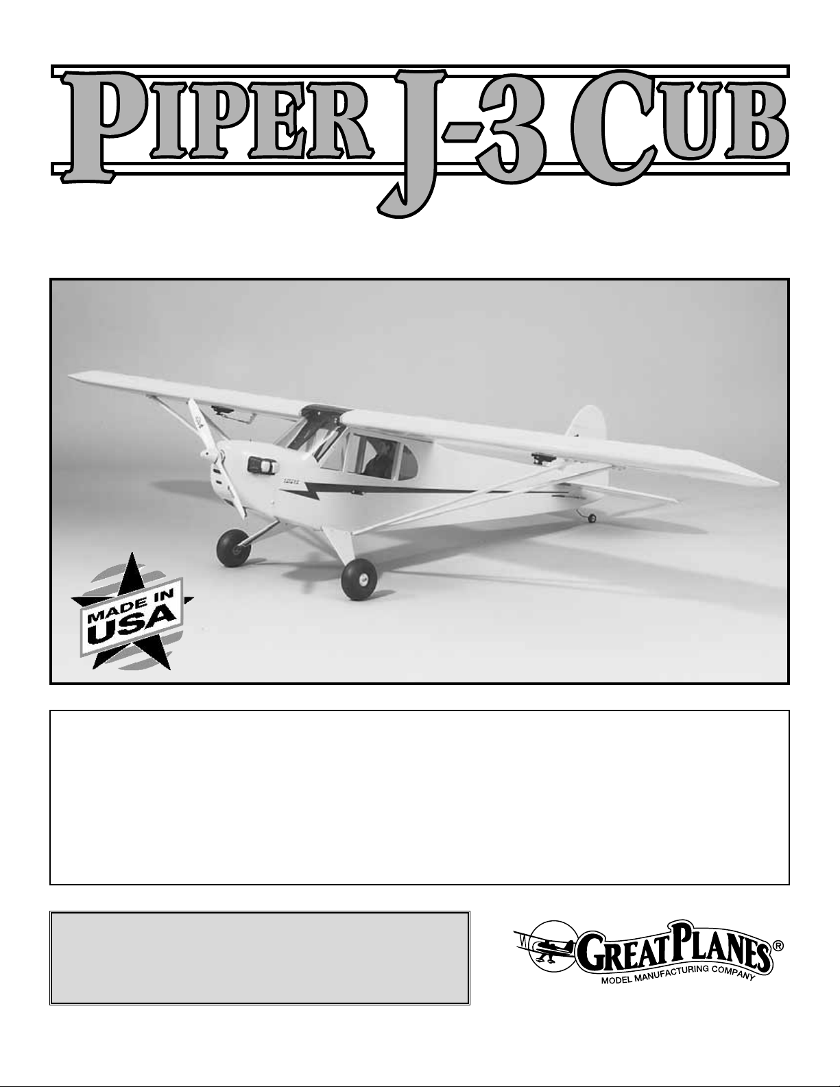
INSTRUCTION MANUAL
QQUUAARRTTEERR SSCCAALLEE
A.R.F.
Almost Ready to Fly
Page 2
Important Safety Precautions . . . . . . . . . . . . . . . . . . . 2
Introduction . . . . . . . . . . . . . . . . . . . . . . . . . . . . . . . . . 3
Decisions You Must Make . . . . . . . . . . . . . . . . . . . . . . 3
Engine Selection. . . . . . . . . . . . . . . . . . . . . . . . 3
Preparations . . . . . . . . . . . . . . . . . . . . . . . . . . . . . . . . 3
Required Accessories . . . . . . . . . . . . . . . . . . . . 3
Building Supplies and Tools. . . . . . . . . . . . . . . . 3
Optional Supplies and Tools . . . . . . . . . . . . . . . 4
General Inspection . . . . . . . . . . . . . . . . . . . . . . 4
Inch/Metric Ruler. . . . . . . . . . . . . . . . . . . . . . . . 4
Parts List . . . . . . . . . . . . . . . . . . . . . . . . . . . . . 5
Begin Construction . . . . . . . . . . . . . . . . . . . . . . . . . . . 6
Fuelproof the Fuselage . . . . . . . . . . . . . . . . . . . 6
Join the Wing Halves . . . . . . . . . . . . . . . . . . . . 6
Mount the Engine . . . . . . . . . . . . . . . . . . . . . . . 6
Install the Fuel Tank . . . . . . . . . . . . . . . . . . . . . 8
Mount the Wing. . . . . . . . . . . . . . . . . . . . . . . . . 9
Mount the Stab & Fin . . . . . . . . . . . . . . . . . . . 10
Install the Tail Landing Gear . . . . . . . . . . . . . . 11
Install the Main Landing Gear . . . . . . . . . . . . . 12
Install the Elevator Joiner Wire . . . . . . . . . . . . 13
Join The Control Surfaces . . . . . . . . . . . . . . . . 14
Hook up the Ailerons. . . . . . . . . . . . . . . . . . . . 15
Radio Installation . . . . . . . . . . . . . . . . . . . . . . 16
Pushrod Installation. . . . . . . . . . . . . . . . . . . . . 17
Throttle Pushrod Installation . . . . . . . . . . . . . . 18
Final Assembly . . . . . . . . . . . . . . . . . . . . . . . . . . . . . 19
Windshield Installation. . . . . . . . . . . . . . . . . . . 19
Strut Installation . . . . . . . . . . . . . . . . . . . . . . . 19
Control Throw Adjustment. . . . . . . . . . . . . . . . 21
Balance the Model Laterally . . . . . . . . . . . . . . 21
Preflight . . . . . . . . . . . . . . . . . . . . . . . . . . . . . . . . . . . 22
Charge the Batteries . . . . . . . . . . . . . . . . . . . . 22
Balance the Propeller . . . . . . . . . . . . . . . . . . . 22
Find a Safe Place to Fly . . . . . . . . . . . . . . . . . 22
Ground Check the Model . . . . . . . . . . . . . . . . 22
Range Check Your Radio . . . . . . . . . . . . . . . . 22
Engine Safety Precautions . . . . . . . . . . . . . . . 23
AMA Safety Code (excerpt) . . . . . . . . . . . . . . . . . . . . 23
General. . . . . . . . . . . . . . . . . . . . . . . . . . . . . . 23
Radio Control . . . . . . . . . . . . . . . . . . . . . . . . . 23
Flying . . . . . . . . . . . . . . . . . . . . . . . . . . . . Back Cover
Takeoff . . . . . . . . . . . . . . . . . . . . . . . Back Cover
Flight. . . . . . . . . . . . . . . . . . . . . . . . . Back Cover
Landing. . . . . . . . . . . . . . . . . . . . . . . Back Cover
Engine Mount Template . . . . . . . . . . . . . . . Back Cover
Your Piper Cub ARF is not a toy, but rather a sophisticated,
working model that functions very much like an actual
airplane. Because of its realistic performance, the Piper Cub
ARF, if not assembled and operated correctly, could possibly
cause injury to yourself or spectators and damage property.
To make your R/C modeling experience totally enjoyable, we
recommend that you get experienced, knowledgeable help
from an instructor with assembly and during your first flights.
You’ll learn faster and avoid risking your model before you’re
truly ready to solo. Your local hobby shop has information
about flying clubs in your area whose membership includes
qualified instructors. You may also contact the national
Academy of Model Aeronautics (AMA), which has more
than 2,500 chartered clubs across the country. Contact the
AMA at the address or toll-free phone number below.
Academy of Model Aeronautics
5151 East Memorial Drive
Muncie, IN 47302-9252
Tele. (800) 435-9262
Fax (765) 741-0057
or via the Internet at http://www.modelaircraft.org
1. Assemble the plane according to the instructions. Do not
alter or modify the model, as doing so may result in an
unsafe or unflyable model.
2. Take time to align the components straight and true.
3. Use an R/C radio system that is in first-class condition,
and a correctly-sized engine and components (fuel tank,
wheels, etc.) throughout your assembly process.
4. You must properly install all components so that the
model operates properly on the ground and in the air.
5. You must check the operation of the model before every
flight to ensure that all equipment is operating and that the
model has remained structurally sound. Be sure to check
nylon clevises or other connectors often and replace them if
they show signs of wear or fatigue.
PRECAUTIONS
PROTECT YOUR MODEL,YOURSELF
& OTHERS...FOLLOW THIS
IMPORTANT SAFETY PRECAUTION
TABLE OF CONTENTS
2
Page 3
Remember: Take your time and follow directions to end
up with a well-built model that is straight and true.
Please inspect all parts carefully before starting to
build! If any parts are missing, broken or defective, or if
you have any questions about assembling or flying this
airplane,
please call us at (217) 398-8970 or e-mail us at
productsupport@greatplanes.com. If you are calling for
replacement parts, please reference the part name and
number (See page 5) and have them ready when calling.
The Great Planes Piper Cub ARF is an easy-to-fly
sport-scale airplane that closely resembles the full size
Piper Cub both in appearance and performance. The Piper
Cub ARF is very stable and predictable, allowing even
novice skill level pilots to enjoy it.
Because of its docile flight characteristics, this airplane could
be used as a first airplane for learning to fly, but only with the
assistance and close supervision of a competent instructor.
This airplane lacks the self-recovery characteristics of a true
“basic trainer” such as the Great Planes PT
™
series, which is
the model of choice for learning to fly.
Items in parentheses (OSMG2691) are suggested part
numbers recognized by distributors and hobby shops and
are listed for your ordering convenience. GPM is the Great
Planes
®
brand, TOP is the Top Flite®brand, and HCA is the
Hobbico®brand.
❏ 4 Channel Radio with 5 Servos
❏ “Y” Harness For Aileron Servos
❏ Two 6" Servo Extensions For Aileron Servos
❏ Engine – See Engine Selection
❏ Spare Glow Plugs (O.S. #8 For Most 2-Stroke Engines,
OSMG2691) Type F for 4-stroke (OSMG2692)
❏ Propeller (Top Flite
®
Power Point®)
(Refer To Your Engine’s Instructions For Proper Size)
❏ 3’ Medium 3/32" Fuel Tubing (GPMQ4131)
❏ 1/4" Latex Foam Rubber Padding (HCAQ1000)
❏ Fueling System (Great Planes Top Fueler
™
, GPMQ4160)
❏ 8-32 Tap & #29 Drill Bit (GPMR8103)
These are the building tools that are required. We recommend
Great Planes Pro
™
CA and Epoxy glue.
❏ 2 oz. Pro CA (Thin, GPMR6003)
❏ 2 oz. Pro CA+ (Medium, GPMR6009)
❏ CA Accelerator (GPMR6035)
❏ 6-Minute Pro Epoxy (GPMR6045)
❏ 30-Minute Pro Epoxy (GPMR6047)
❏ Canopy Glue (JOZR5007)
❏ Hobby Knife (HCAR0105) & Blades (HCAR0311)
❏ Builders Triangle Set (HCAR0480)
❏ Masking Tape (TOPR8018)
❏ Slip-Joint & Needle Nose Pliers
❏ Monofilament String For Stabilizer Alignment
❏ Screwdrivers (Flat Blade & Phillips)
❏ Pro Thread Locking Compound (GPMR6060)
❏ Isopropyl Alcohol (70%)
❏ Drill & Drill Bits: 1/16" [1.6mm], 5/64" [2mm], 3/32"
[2.4mm], 3/16" [4.8mm], 7/32" [5.6mm], 1/4" [6mm], #29
❏ Top Flite Trim Seal Tool
™
(TOPR2200)
❏ Panel Line Pen (TOPQ2510)
❏ Sandpaper: 80, 220 & 320-grit
❏ Metal File
❏ 3/4 Oz. Fiberglass cloth (HCAR5000)
❏ Paper Towels
❏ T-Pins (HCAR5100)
❏ 1/4-20 x 1" Steel Bolt & 1/4" Washer
❏ Hobby Heat
™
Micro Torch (HCAR0750)
❏ Silver Solder (GPMR8070)
❏ Razor Saw
❏ Petroleum Jelly
Building Supplies and Tools
Required Accessories
PREPARATIONS
Engine Selection
There are several engines that will work well in your Piper
Cub ARF. We recommend an O.S.®FS-70 4-stroke for the
best scale appearance and sound for your Piper Cub. A hot
2-stroke such as an O.S. .46FX or SuperTigre®G45 would
also be a good choice. Another option for a 2-stroke would
be a mild .60, such as the O.S. .65 LA or O.S. .60 FP. Your
choice of 2-stroke or 4-stroke will determine the location of
the throttle servo and throttle pushrod exit on the firewall, so
plan ahead.
DECISIONS YOU MUST MAKE
INTRODUCTION
NOTE: We, as the manufacturer, provide you with a top
quality kit and great instructions, but ultimately the quality of
your finished model depends on how you assemble it;
therefore, we cannot in any way guarantee the performance
of your completed model, and no representations are
expressed or implied as to the performance or safety of your
completed model.
3
Page 4
4
❏ CG Machine
™
(GPMR2400)
❏ Dremel®MultiPro™Or Similar W/Cut-Off Wheel
❏ Dead Center™Engine Mount Hole Locator (GPMR8130)
❏ Groove Tube™Grooving Tool (GPMR8140)
❏ Curved Tip Canopy Scissors (HCAR0667)
❏ Switch and Charge Jack (GPMM1000)
❏ 6 Oz. Segmented lead weight (GPMQ4485)
Eliminate any wrinkles you find in the covering by shrinking
them away with a low temperature setting on a heat gun, then
apply pressure to the area with a covering iron and a hot
sock. This will securely bond the covering to the wood so the
wrinkles will be less likely to reappear in the future.
AMA =
Academy of Model Aeronautics
ARF = almost ready to fly
Deg = degrees Elev = elevator
Fuse = fuselage " = inches
LE = leading edge Ply = plywood
Stab = stabilizer TE = trailing edge
LG = landing gear mm = millimeters
1/64" = .4mm
1/32" = .8mm
1/16" = 1.6mm
3/32" = 2.4mm
1/8" = 3.2mm
5/32" = 4mm
3/16" = 4.8mm
1/4" = 6.4mm
3/8" = 9.5mm
1/2" = 12.7mm
5/8" = 15.9mm
3/4" = 19mm
1" = 25.4mm
2" = 50.8mm
3" = 76.2mm
6" = 152.4mm
12" = 304.8mm
15" = 381mm
18" = 457.2mm
21" = 533.4mm
24" = 609.6mm
30" = 762mm
36" = 914.4mm
1" = 25.4mm (conversion factor)
Metric Conversions
Common Abbreviations
General Inspection
Optional Supplies and Tools
Page 5
5
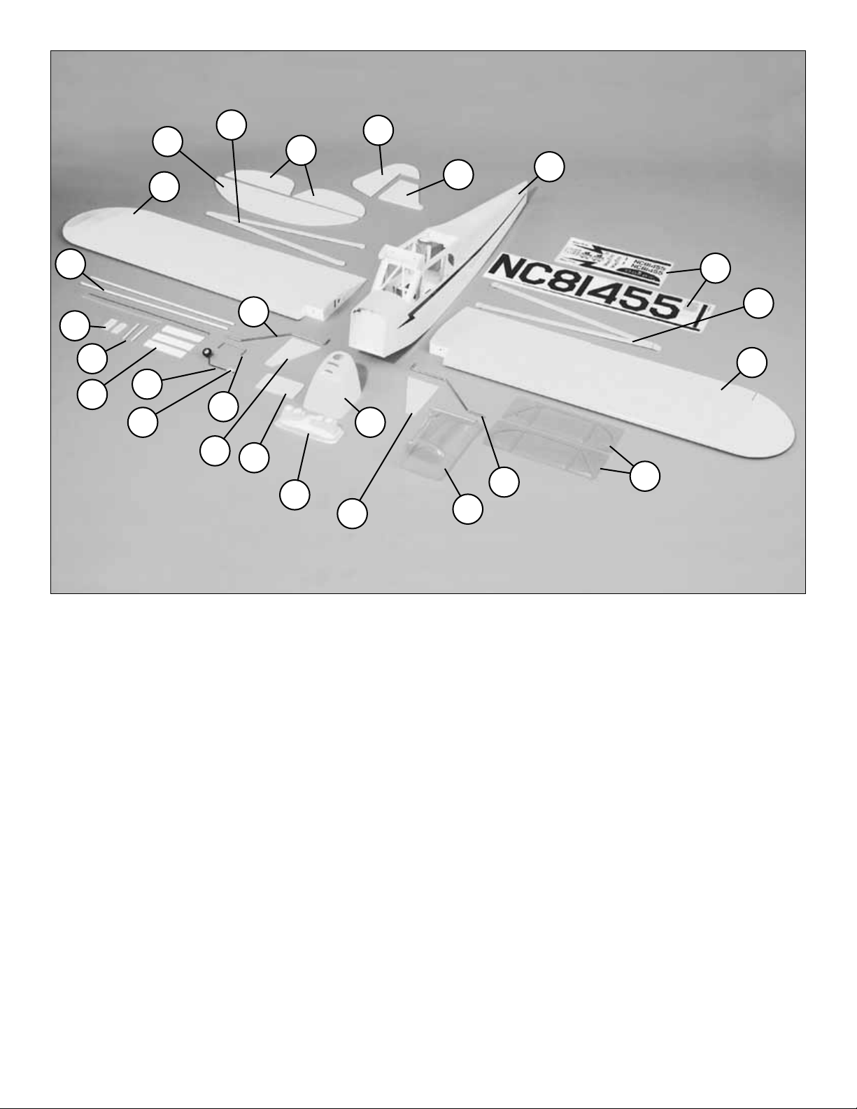
Key# Description Qty
1 Fuselage . . . . . . . . . . . . . . . . . . .1
2 Left Wing Panel w/Aileron . . . . . . .1
3 Right Wing Panel w/Aileron . . . . . .1
4 Cowl . . . . . . . . . . . . . . . . . . . . . . .1
5 Decals . . . . . . . . . . . . . . . . . .1 Set
6 Side Windows . . . . . . . . . . . . . . . .2
7 Canopy . . . . . . . . . . . . . . . . . . . .1
8 Right Landing Gear Cover . . . . . .1
9 Left Landing Gear Cover . . . . . . .1
10 Landing Gear . . . . . . . . . . . . . . . .1
11 Wing Bolt Plate . . . . . . . . . . . . . . .1
12 Stabilizer . . . . . . . . . . . . . . . . . . .1
13 Elevator Assembly . . . . . . . . . . . .1
14 Rudder . . . . . . . . . . . . . . . . . . . . .1
15 Vertical Fin . . . . . . . . . . . . . . . . . .1
16 Tail Wheel Assembly . . . . . . . . . . .1
17 Tail Wheel Bracket . . . . . . . . . . . .1
18 Wing Struts . . . . . . . . . . . . . . . . .2
19 Elevator Joiner Wire . . . . . . . . . . .1
20 Dummy Engine . . . . . . . . . . . . . . .1
21 Wing Joiners . . . . . . . . . . . . . . . .3
22 Landing Gear Fairing Mounts . . . .2
23 Wing Dowels . . . . . . . . . . . . . . . .2
24 Pushrods . . . . . . . . . . . . . . . .1 Set
Parts Not Shown In Photo
Description Qty
Adjustable Engine Mount . . . . . . . . . . . . .1
Main Wheels . . . . . . . . . . . . . . . . . . . . . .2
Servo Tray . . . . . . . . . . . . . . . . . . . . . . . .1
CA Hinge Strip (2" x 9") . . . . . . . . . . . . . .1
Hardware Bag . . . . . . . . . . . . . . . . . . . . .1
Replacement Parts
If needed, replacement parts for Piper Cub ARF are
available through your hobby supplier.
Wing Set . . . . . . . . . . . . . . . . . . . . .GPMA2180
Fuselage Kit . . . . . . . . . . . . . . . . . . .GPMA2181
Tail Fin Set . . . . . . . . . . . . . . . . . . . .GPMA2182
Canopy . . . . . . . . . . . . . . . . . . . . . .GPMA2183
Cowl . . . . . . . . . . . . . . . . . . . . . .GPMA2184
Landing Gear Set . . . . . . . . . . . . . . .GPMA2185
1
2
3
4
5
7
8
9
10
10
11
12
13
14
15
16
17
18
18
19
20
21
22
23
24
6
Page 6
6
❏ 1. Coat the firewall and all other bare wood around the
firewall with fuelproof paint or 30-minute epoxy thinned with
alcohol. Fuelproof other areas of bare wood in the fuselage
that may be exposed to fuel or engine exhaust, such as the
fuel tank area and the front and back of the wing saddle.
❏ 2. Set the fuselage aside while the paint or epoxy dries.
❏ 1. Cut the covering 1/8" inside the edges of the opening
in the bottom of the Right Wing Panel for the aileron servo.
Use your Top Flite MonoKote
®
Trim Seal Tool™to seal the
covering to the sides of the opening.
Note: You’ll notice a piece of string that passes through the
covering at the location of the aileron servo. Don’t remove
the string because you will use it to pull your aileron servo
cord through the wing later.
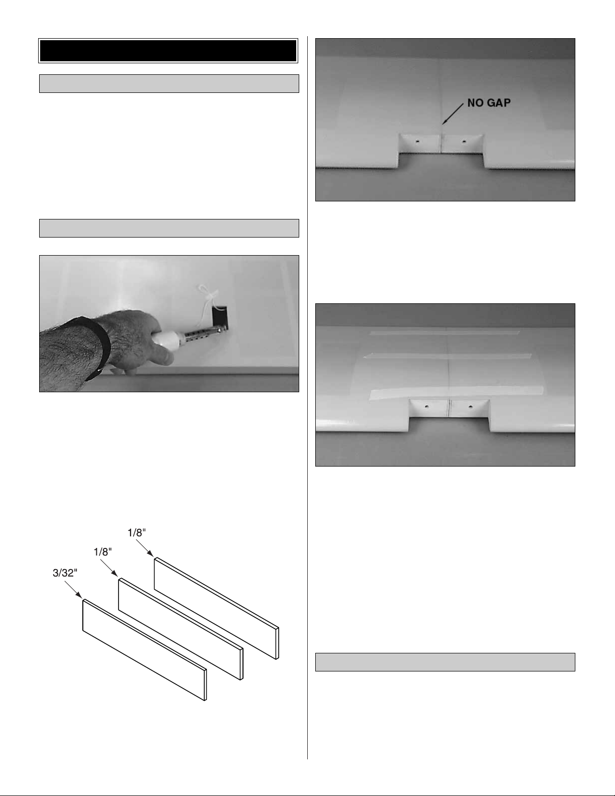
❏ 2. Use 30-minute epoxy to glue the two 1/8" x 1-1/8" x
5-1/4" [3mm x 28mm x 133mm] plywood Wing Joiners and
the 3/32" x 1-1/8" x 5-1/4" [2.4mm x 28mm x 133mm]
plywood wing joiner together. Wipe away any excess epoxy.
❏ 3. Test fit the wing halves with the wing joiner. If necessary,
sand any high spots on the root end of the wing panels so
there is no gap when you join them. Since the wing is built
with no dihedral, it can be built flat on your work surface.
Make a
dry run
of the following step
without using any glue
so you will know how to clamp your wing together.
❏ 4. Tape a piece of wax paper or plan protector over your
work surface. Thoroughly coat the joiner pockets and the
mating ends of both wing halves with 30-minute epoxy. Set
the wing halves aside and proceed quickly. Coat all surfaces
of one half of the wing joiner with 30-minute epoxy and
place it in one of the wing halves. Coat the other half of the
joiner with 30-minute epoxy and join the other wing. Use a
piece of balsa or cardboard to wipe away excess epoxy. Use
masking tape to tightly tape the wing together. Use a tissue
dampened with alcohol to wipe away any more epoxy that
oozes out of the wing, then set the wing aside. Do not
disturb the wing until the epoxy has fully cured.
❏ 1. Cut or break the “spreader bar” from each Engine
Mount half. Carefully trim any extra material left by the
spreader bar from each mount half. The surfaces where the
spreader bars were attached must be smooth to allow the
mount halves to fit together. Trim the flashing off any rough
edges if necessary.
Mount the Engine
Join the Wing Halves
Fuelproof the Fuselage
BEGIN CONSTRUCTION
Page 7
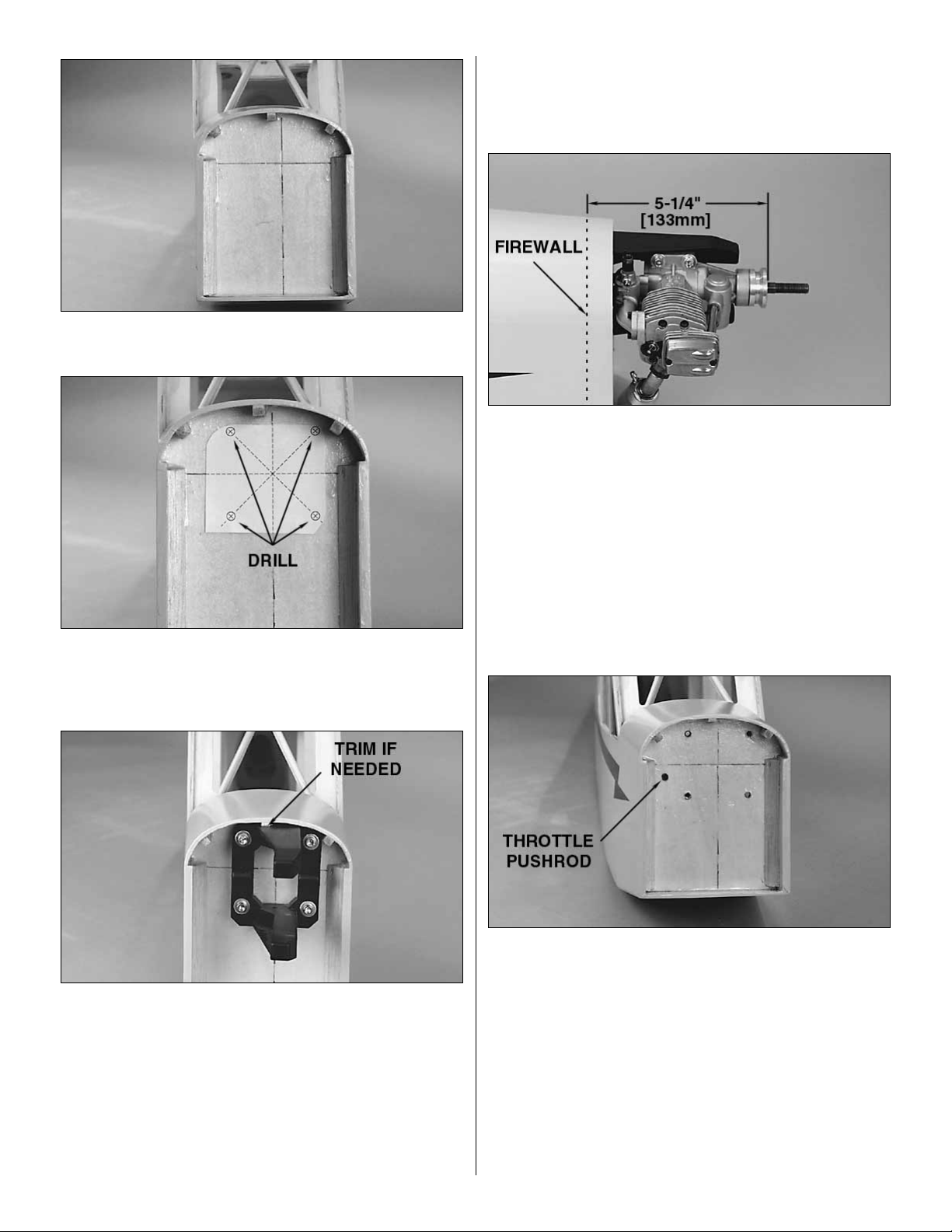
❏ 2. Extend the marks on the firewall to locate the position
for the engine mount on the firewall.
❏ 3. Cut the Engine Mount Template from the back cover
of the manual and tape it to the firewall as shown. At the
locations on the template, drill four 7/32" [5.6mm] holes in
the firewall for the engine mount blind nuts.
❏ 4. Install four 8-32 Blind Nuts to the inside of the firewall.
Pull the blind nuts into the back side of the firewall using
8-32 Socket Head Cap Screws with a flat washer under
the head of the screws. Fit the two halves of the Engine
Mount together. Use four #8 Flat Washers and four 8-32 x
1" Socket Head Cap Screws to secure the engine mount to
the firewall. Do not tighten the screws at this time, as the
mount must be adjusted for the engine. Depending on your
engine selection, it may be necessary to trim the top center
stringer to allow for positioning the engine mount.
❏ 5. Test fit your engine into the mount. Adjust the width of
the rails to fit the engine snugly. Tighten the mount screws
to allow marking the engine mounting holes without moving
the rails.
❏ 6. Position the engine on the engine mount rails so the
propeller thrust washer is 5-1/4" [133mm] ahead of the
firewall. Use a Great Planes Dead Center Hole Locator
(GPMR8130) (not included) or a sharpened piece of wire to
scribe the four engine mount holes onto the rails. Use a
center punch at the marks to prevent the drill bit from
wandering, then drill #29 pilot holes through the rails. Be
sure to hold the drill perpendicular to the rails. If you have
access to a drill press, this is a good tool for this purpose.
Use an 8-32 tap to tap the holes for the 8-32 screws. Use
four 8-32 x 1" socket head cap screws to secure the engine
to the mount.
❏ 7. Drill a 3/16" [4.7mm] hole in the firewall for the throttle
pushrod. The hole location will depend on whether you are
installing a 2-stroke or 4-stroke engine.
❏ 8. Roughen the outside surface of the 11-3/4" [298mm]
Throttle Pushrod Tube with coarse grit sandpaper. Insert
the pushrod tube through the hole in the firewall. Push it in
until it is flush with the front of the firewall. Use medium CA
to glue the tube to the firewall, but leave it free inside the
fuselage until the servos are installed.
Note: The engine has been removed from the above picture
for clarity.
7
Page 8
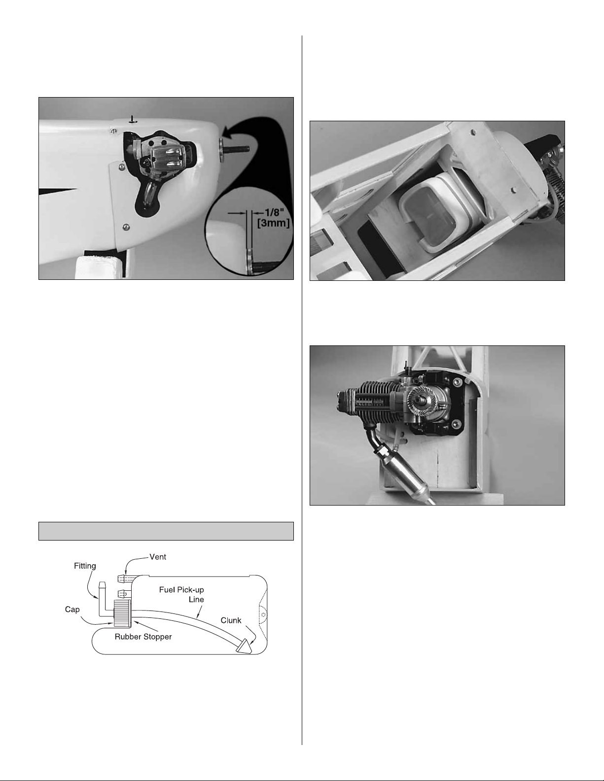
❏ 9. Slip the Cowl over the front of the fuse. Cut a hole in
the cowl just large enough to accommodate the engine.
After the cowl is mounted, you can enlarge the hole to allow
some clearance for a more finished appearance.
❏ 10. Align the front of the cowl 1/8" [3mm] behind the drive
washer of the engine and tape it to the fuselage.
❏ 11. Drill a 5/64" [2mm] hole through the cowl into the
fuselage. Screw a #4 x 1/2" Sheet Metal Screw through the
cowl just far enough into the fuselage to temporarily hold
that part of the cowl in place. One at a time, drill a hole and
insert a screw into the cowl the same way. Depending on
the engine, you may use either four or five screws to secure
the cowl.
❏ 12. Remove the cowl. Roughen the inside of the cowl
around the screw holes with 80-grit sandpaper. Cut four 1"
square pieces of glass cloth and glue them to the inside of
the cowl over the mounting holes with 30-minute epoxy as
shown in the photo. Set the cowl aside while the epoxy
cures. Use a small amount of epoxy to fuelproof the cowl
mounting blocks.
❏ 1. Cut the clear pick-up tube included with this kit to a
length of 3-3/16" [81mm]. Assemble the fuel tank as shown
in the sketch using the 90-degree nipple. After you
assemble the tank hold it up to the light and make sure the
clunk does not contact the rear of the tank. If necessary,
disassemble the tank and shorten the pick-up tube.
❏ 2. Wrap the tank with 1/4" [6mm] foam rubber secured
with a couple of rubber bands.
❏ 3. Remove the engine mount. Drill 1/4" [6mm] holes
through the firewall for your fuel lines. Make sure to drill the
holes where they will not interfere with the engine mount.
❏ 4. Fit approximately 12" to 14" [300mm to 360mm] of fuel
line on the pick-up and vent nipples of your fuel tank. Pull the
fuel lines through the holes you drilled in the firewall as you
install your tank. Be certain you do not kink the fuel lines.
❏ 5. Mount the muffler to your engine. Trim the cowl where
necessary so it does not interfere with the muffler, allowing
an approximate 1/4" [6mm] clearance all the way around.
Attach the fuel lines from the fuel tank to the engine, making
sure the fuel and pressure lines are correctly attached.
Install the Fuel Tank
8
Page 9

❏ 1. Bevel the ends of the 1/4" [6mm] Hardwood Wing
Dowels.Test fit the dowels into the wing, making sure they lock
into the holes inside the wing. Use 30-minute epoxy to glue the
dowels into the wing, leaving them protrude 5/8" [16mm].
❏ 2. Install the 1/4-20 Blind Nuts by drawing them up into
the wing nut plate with a 1/4-20 bolt and washer (not
included). Apply 30-minute epoxy to the prongs of the blind
nuts before drawing them up into the nut plate to secure
their positions.
❏ 3. Place the wing on the fuselage. Measure from the aft
center of the fuselage to one wing tip and record the
distance. Measure from the same point to the opposite wing
tip and compare it to the first measurement. If the
measurements are not the same, adjust the wing and
remeasure until they are equal. Place a mark on the wing
and fuselage so it can be repositioned accurately for the
following steps.
❏ 4. Remove the covering from the wing center section
where the wing bolts will pass through the wing.
❏ 5. Bolt the wing to the fuselage using the 1/4-20 x 2"
Nylon Bolts. Enlarge the holes if necessary to allow the
bolts to pass through the wing. Check the alignment of the
wing and enlarge the holes in the wing if necessary to allow
the wing to be shifted to match the alignment marks.
❏ 6. Remove the wing and center the Wing Bolt Plate on
the trailing edge of the wing. Trace around the plate with a
pencil. Use a fresh #11 blade to carefully cut through the
covering 1/16" [1.6mm] inside the lines. Do not cut the
wood under the covering! This will weaken the
structure and may cause failure in flight. Remove the
covering from the wing within the lines you cut. Use medium
CA to glue the plate to the wing. Drill the holes for the bolts
in the plate from the bottom of the wing.
Mount the Wing
9
Page 10

❏ 1. Use a fresh #11 blade to trim the covering from the
slots in the aft end of the fuse for the stab and fin.
❏ 2. Measure the Stabilizer and accurately mark the center
with a felt-tip pen. Use a 90-degree triangle to mark a
vertical centerline across the mark you made.
❏ 3. (Refer to this sketch while you align the stab.) Slide the
stab into the fuse. Align the centerline you marked with the
slot for the fin. Measure the stab on both sides of the fuse
to make sure it is centered (A=A).
❏ 4. Remove your cowl if it’s on the fuselage. Insert a T-pin
into the bottom center of the firewall in the front of the
fuselage. Tie a small loop at one end of a 42" [1070mm]
piece of monofilament string and slip it over the T-pin.
❏ 5. Fold a piece of masking tape over the other end of the
string and draw an arrow on it. Slide the tape along the string
and align the arrow with one end of the stab. Swing the string
over to the other end of the stab, while keeping the stab
centered in the fuselage. Shift the stab and slide the tape
along the string until the distances between both ends of the
stab and the front of the fuse are equal (B=B). Now your stab
is centered and square with the fuse.
❏ 6. Use a felt-tip pen to mark the sides of the fuselage
on the top and bottom of the stab. Remove the stab from
the fuselage.
Mount the Stab & Fin
10
Page 11

❏ 7. Use a fresh #11 blade to carefully cut through the
covering 1/16" [1.6mm] inside the lines you marked on the top
and bottom of the stab that indicate the fuse sides. Do not cut
the wood under the covering! This will weaken the
structure and may cause the stab to fail in flight. Remove
the covering from the center of the stab within the lines you cut.
❏ 8. Reinstall the stab in the fuse. Bolt the wing to the fuse
with two 1/4-20 x 2" bolts. View the fuselage from the rear
and make sure the stab is parallel with the wing as shown
in the sketch (A=A). If the stab is not parallel with the wing,
remove the stab and carefully sand the fuse where it
interferes with the stab. Reinstall the stab and recheck
alignment from behind the fuse. Sand the fuse as
necessary until the stab is aligned. Proceed carefully and
remove only a small amount of material at a time.
❏ 9. Now it’s time to glue the stab to the fuse. Position the
stab in the fuse so the exposed balsa of the center section
is visible. Apply a film of 30-minute epoxy to the bare balsa
on both sides of the stab and slide it into position, making
sure you distribute enough epoxy in the opening. Repeat
this procedure once more to make sure you have distributed
plenty of epoxy in the stab saddle. Recheck alignment using
the pin-and-string technique shown earlier. Wipe away
excess epoxy before it cures and use T-pins to hold the stab
in position until the epoxy has fully cured.
❏ 10. Test fit the Fin into the fuselage. Trim where necessary
so the TE of the fin aligns with the end of the fuse.
❏ 11. Use 30-minute epoxy to glue the fin to the fuse. If
necessary, use masking tape to hold the fin perpendicular
to the stab. Apply a thin coat of epoxy to the bare wood on
the TE of the fin. Do not disturb the fuselage until the epoxy
has fully cured.
❏ 1. Slip the Tail Gear Wire into the plastic Tail Gear
Bracket. Make a 90-degree bend in the wire 1-1/2" [38mm]
from the end.
Install the Tail Landing Gear
11
Page 12

❏ 2. Cut a slot in the tail post of the fuselage 3/8" [9.5mm] up
from the bottom of the fuse for the tail gear bracket. Coat the
tail gear wire with petroleum jelly where it slides through the
bracket. Glue the bracket into the slot using 30-minute epoxy.
❏ 3. Hold the rudder to the fin next to the tail gear wire (or
tape the rudder to the fin). Mark the rudder where the arm
portion of the tail gear wire will enter.
❏ 4. Cut a groove in the LE of the rudder and drill a 3/32"
[2.4mm] hole where you made your mark to accommodate
the tail gear wire. Hint: Use a 3/32" [2.4mm] brass tube
sharpened at the end to cut the groove. (The Groove Tube
™
Grooving Tool (GPMR8140) works great for this task.)
❏ 5. Test fit the rudder to the tail gear wire. View the rudder and
the tail gear wire from above (when the fuselage is upsidedown in your cradle). If necessary, bend the tail gear wire so
your model will taxi straight when your rudder is centered.
❏ 1. Use a fresh #11 blade to trim the covering from the slot
in the fuselage for the main landing gear.
❏ 2. Test fit the Main Landing Gear. It’s helpful if you use a
file to remove any burrs or sharp edges from the ends of the
wire. Seat the landing gear wire in the landing gear rail on
the fuselage. Use a Nylon Landing Gear Strap as a guide
to drill 1/16" [1.6mm] pilot holes for the screws. Secure the
landing gear with two nylon straps and four #2 x 1/2" Sheet
Metal Screws.
❏❏3. Position the landing gear fairing mounts on the landing
gear fairings as shown in the photo. The hinge line of the
mount must align with the edge of the fairing. Mark the
location of the mount and remove the underlying covering
from the fairing. Use 6-minute epoxy to glue the mount to the
fairing. Make both a right and left gear fairing assembly.
Install the Main Landing Gear
12
Page 13

❏❏4. Locate and remove the covering from the notches
of the landing gear fairing. Fuelproof the exposed wood
with epoxy.
❏❏5. Drill two 3/32" [2.4mm] holes in the landing gear
fairing mounts as shown. The exact spacing of these holes
is not important.
❏❏6. Drill 1/16" [1.6mm] pilot holes into the fuselage and
mount the landing gear fairing assembly using two #2 x 1/2"
sheet metal screws. Use a small rubber band to hold the
bottom of the fairing to the landing gear strut.
❏❏7. Install the main wheels using four 7/32" Wheel
Collars and four 8-32 Set Screws. Drill the hub of the wheels
using a 7/32" [5.6mm] drill bit if necessary so they fit onto the
axle. Grind or file a flat spot at the point of set screw contact.
This provides a better area for the set screw to bite and helps
keep the wheel in place. Trim off any excess axle wire after
installing the wheel collar. Use threadlock on the set screws
to prevent loosening.
❏ 1. Use a razor saw to remove the aft fuselage tail post
behind the stabilizer.
❏❏2. Tape the Elevator halves to the stabilizer. Position
the Elevator Joiner Wire on the halves and mark the
location of the joiner onto the elevators.
Install the Elevator Joiner Wire
13
Page 14

❏❏3. Cut a groove in the LE of the elevators and drill 3/32"
[2.4mm] holes where you made your marks to accommodate
the elevator joiner wire. Hint: Use a 3/32" [2.4mm] brass tube
sharpened at the end to cut the groove. (The Groove Tube
™
Grooving Tool (GPMR8140) works great for this task.)
❏❏4. Use 30-minute epoxy to glue the elevator joiner wire
into the elevators. Use a straightedge as shown in the photo
to align the leading edge of the elevators. Use weights to
hold the elevators in position until the epoxy cures.
❏ 1. Cut twelve 3/4" x 1" [19mm x 25mm] hinges from the
CA hinge strip supplied with this kit. Snip the corners off so
they go into the slots easier.You may cut all the hinges now,
or cut them as you need them.
❏ 2. Test fit the elevators to the stab. If the hinges are
difficult to install or don’t go in far enough, carefully enlarge
the hinge slots with a hobby knife and a #11 blade.
❏ 3. Drill a 3/32" [2.4mm] hole, 1/2" [13mm] deep, in the
center of the hinge slot. If you use a Dremel® MultiPro™ for
this task, it will result in a cleaner hole than if you use a
slower speed drill. Drilling the hole will twist some of the
wood fibers into the slot, making it difficult to insert the
hinge, so you should reinsert the knife blade, working it
back and forth a few times to clean out the slot.
❏ 4. If the hinges don’t remain centered, remove the
elevator and insert a pin in the center of the hinges.
Before you glue in the hinges, apply a few drops of
household oil to a tissue. Wipe the tissue over the trailing
edge of the stabilizer and the leading edge of the
elevators, coating them with a fine film of oil. This will
prevent excess CA from sticking to the stab and elevator
at the hinge gap while you are gluing in the hinges.
Join the Control Surfaces
14
Page 15

❏ 5. Cut a paper towel into approximately 2" [50mm]
squares. Add six drops of thin CA to the center of the hinges
on both sides. Use the paper towel squares to absorb
excess CA from the hinge gap before it cures. Do not use
CA accelerator; allow the CA to cure slowly.
❏ 6. Pack the tail gear wire hole and the groove in the LE of
the Rudder with epoxy. If you work quickly, you may use 5minute epoxy, but we recommend 30-minute epoxy. Join the
rudder to the fin using two hinges. Use a tissue dampened
with alcohol to wipe away excess epoxy before it cures.
Make sure there is approximately a 1/32" [.8mm] gap
between the rudder and the fin. Place the fuselage on its
side so the fin and rudder are horizontal. Add six drops of
thin CA to the center of the hinges on both sides. Use the
paper towel squares to absorb excess CA from the hinge
gap before it cures. Do not use CA accelerator; allow the CA
to cure slowly.
❏❏7. Use the same hinging method to join the ailerons to
the wing.
❏ 8. After all control surfaces are securely hinged and the
CA has thoroughly cured, move the control surfaces back
and forth to loosen them up a little so it will be easier for
your servos to move them.
❏❏1. If you haven’t already done so, install the rubber
grommets and eyelets in your aileron servos. Attach a servo
extension to the aileron servo. Use heat-shrink tubing or
electrical tape to secure the servo cord to the extension so
they don’t unplug in flight. Pull the string part-way out of one
of the aileron servo compartments in the wing. Tie the string
to the servo cord on one of the aileron servos.
❏❏2. Fit one of the aileron servos in the wing. Hold the servo
to the wing so the sides don’t contact the wing and drill 1/16"
[1.6mm] holes for the servo mounting screws. Mount the servo
to the wing with the screws included with your servos.
❏❏3. Mount your other aileron servo in the opposite wing
panel using the same procedures as above.
❏❏4. Cut the unused arms from one of the servo horns
and mount it on one of the aileron servos in the wing. When
installing the arms onto the servos, position the arms as
shown in the sketch so the ailerons will move opposite each
other when using a "Y" harness.
❏❏5. Refer to the following photo. Use alcohol or other
solvent to clean the film of oil from the two 2-56 x 6" Wire
Pushrods. Screw a Nylon Clevis about fourteen turns onto
one of the pushrods. Connect the clevis to the outer hole of
a nylon control horn.
❏❏6. Hold the control horn on the aileron, making sure the
holes align with the hinge line. Use the control horn as a
template to drill 1/16" [1.6mm] holes through the aileron for
the mounting screws.
Hook Up the Ailerons
15
Page 16

❏❏7. Screw the #2 x 1/2" self tapping screws into the
holes. Remove the screws and apply three drops of thin CA
to each hole to harden the underlying balsa. After the CA
has fully cured, attach the control horns using the #2 x 1/2"
self tapping screws.
❏❏8. Use a felt-tip pen to mark the pushrod wire where it
crosses the holes in the aileron servo arm.
❏ 9. Bend the pushrod at the mark you made. Cut the
excess wire as shown in the sketch and connect the
pushrod to the servo arm with a nylon FasLinkTm.
❏ 10. Return to step 4 and connect the other aileron servo
to the other aileron the same way.
❏ 11. Turn the wing over. Locate the hole in the bottom of
the wing for the servo leads to exit. Remove the covering
from the holes using a sharp hobby knife. Pull the string out
of the 1/2" [13mm] holes in the bottom center section of the
wing to retrieve your aileron servo cords. Connect both
aileron servo cords to a "Y" harness.
❏ 1. Use the following sequence for mounting the servos
into the servo tray in the fuselage:
A. Install rubber grommets and brass eyelets in the
servos as shown in the sketch above.
B. Test fit the servos in the tray. Enlarge the openings
if needed to create a 1/32" [.8mm] gap around
the servo.
C. Mark servo mounting hole locations on the tray, then
drill 1/16" [1.6mm] pilot holes through each mark.
D. Mount the servos with the screws provided with
your radio system.
❏ 2. Install and hook up - following the manufacturer’s
recommendations - three servos, the receiver, switch and
battery as shown in the photo. We added a Great Planes
Switch Mount & Charge Jack (GPMM1000, not included) for
convenience and ease of use at the field, installed on the
side of the fuselage. Center the elevator, rudder and throttle
trims on the transmitter.
Radio Installation
16
Page 17

❏ 1. Cut 1" long slots in both sides of the fuselage for the
elevator and rudder Pushrod Tubes to exit the fuselage.
Use the measurements in the photo for locating the position
of the exits.
❏ 2. Use a 3/16" [4.8mm] drill bit to bevel the holes for
easier installation of the pushrod tubes.
❏ 3. Locate the two 36" [910mm] Outer Pushrod Guide
Tubes and scuff the outside with coarse grit sandpaper. Route
the tubes through the fuselage and into the radio
compartment. The tubes must protrude at least 1-1/2" [38mm]
from the fuse side exits.
❏ 4. Cut the pushrod tubes 1-1/2" [38mm] behind the servo
openings in the servo tray.
❏❏5. Insert one of the 4-40 x 36" [910mm] Threaded End
Rods into the rudder tube in the fuselage. The pushrod
should slide easily into the tube. Screw a 4-40 nut and a 4-40
steel clevis on the pushrod and add a silicone retainer to the
clevis. The threaded rod should protrude slightly inside the
forks of the clevis.
❏❏6. Install the nylon rudder control horn in line with the
pushrod. Hold the horn in position and mark the location of
Pushrod Installation
17
GP
Page 18

the mounting holes. Drill 3/32" [2.4mm] mounting holes
through the marks. Wick two to three drops of Thin CA into
the holes to harden the underlying balsa, then re-drill the
holes. Attach the horns using 2-56 x 5/8" Machine Screws
and Nylon Nut Plates. Do not over-tighten the screws,
crushing the underlying balsa.
❏❏7. Center the rudder and rudder servo and mark the
pushrod where it crosses the servo arm. Remove the
pushrod from the aircraft. Cut the pushrod wire 3/4" [19mm]
behind the mark.
Use the following sequence to solder the clevis to the
pushrod wire:
A. Lightly sand the pushrod wire and clean it with alcohol.
B. Insert the pushrod into the non-threaded clevis. The
wire should protrude 1/16" inside the forks of the clevis.
C. Apply a small amount of soldering flux to the joint.
D. Apply heat evenly to the pushrod wire and the
clevis and then touch the solder to the joint and
allow it to flow.
E. Allow the pushrod and clevis to cool before
continuing.
❏❏8. Remove the threaded clevis and nut from the
pushrod. Slide a clevis retainer from the threaded end onto
the clevis just soldered. Slide the pushrod, threaded end
first, into the pushrod tube from the servo compartment.
Attach the clevis to the outer hole of the servo arm. Thread
the nut and clevis back onto the pushrod wire and attach the
clevis to the rudder control horn.
❏ 9. Repeat steps 5 through 8 to assemble and install the
elevator pushrod.
❏ 10. A pushrod brace must be installed to prevent the
pushrods from flexing near the servos. We used 1/4" balsa
to make the brace shown. This brace can be made using
mixing sticks or any other woods you may have lying
around. The brace must be positioned so it won’t cause the
pushrods to bind against the tubes when installed. Glue the
pushrod tubes to the brace using medium CA.
❏ 1. Install a Brass Screw-Lock Pushrod Connector with
the 4-40 x 1/8" Cap Screw on the throttle servo horn. Snap
the Nylon Retainer onto the pushrod connector post
beneath the servo horn.
❏ 2. Assemble the 17-1/2" [444mm] Throttle Pushrod Wire
by installing a nylon clevis and silicone retainer onto the
threaded end. Slide the throttle pushrod into its outer tube
(from the firewall).
❏ 3. Bend the Throttle Pushrod as necessary to reach the
throttle arm without binding. When satisfied with the fit, insert
the pushrod through the Screw-Lock Pushrod Connector on
the servo. Connect the clevis to the throttle on the engine,
snap the clevis closed, then slide the retainer in place.
Throttle Pushrod Installation
18
Page 19

❏ 4. With the radio switched on, move the throttle trim and
control stick to the fully closed position by pulling them back
(or downward) all the way. Manually close the throttle on the
carburetor completely. Tighten the Cap Screw on the screwlock pushrod connector. Check throttle operation with the
radio and make adjustments to the linkages as necessary
for smooth operation. Use the appropriate holes in the servo
and throttle arms to provide the correct amount of throttle
movement and to prevent the servo from binding at its end
points. Once everything is adjusted, install a brace near the
servo for the outer pushrod tube.
❏ 1. Carefully trim the Windshield along the cut lines with
scissors or Lexan®shears.Test fit the windshield on the fuse
as you proceed, making small adjustments as required for
a good fit.
❏ 2. If you wish to paint the windshield, test the paint on a
sample of the canopy material to make sure the paint is
compatible. Straight out of the spray can, Top Flite
LustreKote®is not recommended for painting the clear
plastic your windshield is made from and will eventually curl
it. But, if you have an airbrush, it is possible to paint your
windshield with LustreKote; however, you must use the
following procedure. Spray an ounce or two of LustreKote
through a tube (such as a large drinking straw or a brass
tube) into a container. Let it sit for about an hour or two to
allow the damaging elements to “boil off.” Using an air
brush, you may now spray your windshield with your
specially prepared LustreKote. For airbrushing, we
recommend thinning LustreKote with lacquer thinner. If you
prefer to spray your windshield frame directly from a spray
can, we have had success with Pactra Formula-U and
Chevron paint. Always test your painting methods on
leftover plastic before you try it on your model!
❏ 3. Paint the exposed wood behind the windshield with
black paint. Install pilots if so desired. You can use Top Flite
LustreKote without any special preparations to the paint or
the model. Just make sure to mask off any areas you do not
want painted.
❏ 4. Roughen the bottom 1/8" [3mm] of the inside
windshield edge, being careful not to scratch any exposed
areas. Glue the canopy into position with 6-minute epoxy or
R/C-56 glue.
❏ 5. Trim the Side Windows so 1/32" [.8mm] remains for
the windows to rest on the inside of the fuselage. Because
the windows fit recessed into the fuselage from the inside,
this lip must remain on the windows. Roughen the outside
edges of the windows and glue them inside the fuselage
with 6-minute epoxy or R/C-56 glue.
❏ 1. Attach the wing to the fuse with two 1/4-20 x 2" nylon
bolts. Place the Struts into position, taking note of the
“airfoil” shape of the struts.
❏❏2. Drill a 1/8" [3mm] hole where the strut will attach to
the fuselage and one in each of the ends attaching to the
Strut Installation
Windshield Installation
FINAL ASSEMBLY
19
Page 20

wing. The holes in the wing ends of the struts should be
positioned so they will align with the hardwood blocks in the
wing. Do not drill into the wing or fuselage at this time.
❏❏3. Position the strut on the fuselage and wing. Drill a 3/32"
[2.4mm] hole at the fuselage and the front strut mount only.
Do not drill the hole for the rear strut mount at this time.
❏❏4. Thread a #4 x 1/2" sheet metal screw into the fuselage
and front wing strut mount block. Remove the screws and
place three drops of thin CA into the holes to harden the
threads. Wait until the CA has cured before you continue.
❏❏5. Attach the strut using two #4 x 1/2" sheet metal
screws and two #4 washers.
The following steps are necessary to install the struts so
they do not twist the wing. Work slowly and carefully,
checking the alignment until you are confident the strut will
not twist the wing when attached.
❏❏6. Place your Cub upside-down in an aircraft stand.
Place a level (or incidence meter) on the wing near the
fuselage. Adjust the position of the airplane until the root of
the wing is perfectly level.
❏❏7. Move the level (or incidence meter) out to the tip of
the wing without allowing the position of the main aircraft to
change. Use the level to check the wing to make sure it is
not twisted. If so, carefully twist the wing until it is level.
❏❏8. Once level, mark the location of the rear strut
attachment through the hole in the strut. Remove the strut and
drill the marked location using a 3/32" [2.4mm] drill bit. Follow
the procedure in step 4 to harden the hole for the screw.
❏ 9. Repeat steps 2 through 8 to install the remaining strut.
IMPORTANT: The struts are necessary to safely fly
your Cub. It must not be flown without them installed
under any circumstance.
20
Page 21

By moving the position of the clevis at the control horn
toward the outermost hole, you will decrease the amount of
throw of the control surface. Moving it toward the control
surface will increase the amount of throw. If these
adjustments don’t accomplish the job, you may need to work
with a combination of adjustments by also repositioning the
pushrod at the servo end. Moving the pushrod towards the
center of the servo horn will decrease the control surface
throw – outward will increase it.
Note: Throws are measured at the widest part of the
elevators, rudder and ailerons. If your radio does not have
dual rates, set the control throws to halfway between the
specified high and low rates. We recommend the following
control surface throws as a starting point:
One leading cause of crashes is flying an airplane with its
control throws set differently from those recommended in the
instructions. The Great Planes AccuThrow™(GPMR2405) lets
you quickly and easily measure actual throws first, so you can
make necessary corrections before you fly. Large, no-slip
rubber feet provide a firm grip on covered surfaces without
denting or marring the finish. Spring tension holds AccuThrow’s
plastic ruler steady by each control surface. Curved to match
control motions, the ruler provides exact readings in both
standard or metric measurements. .
Route the antenna to the tail of the model.You may use your
preferred method or the method we use in the Great Planes
model shop. Drill a 1/4" [6mm] hole through the fuse side in
the proximity of the receiver. Cut a 1/2" [13mm] long piece
of fuel tubing and install it in the hole. Install a strain relief
(as shown in the sketch), then route the antenna through the
fuel tubing to the bottom of the fuse at the tail. Use a rubber
band to attach the antenna to a T-pin. Do not cut or shorten
the antenna wire. Leave any excess antenna wire hang free.
❏ Make sure the control surfaces move in the proper
direction as illustrated in the sketch.
IMPORTANT: Do not confuse this procedure with “checking
the C.G.” or “balancing the airplane fore and aft.”
Now that you have the basic airplane nearly completed, this
is a good time to balance the airplane laterally (side-toside). Here is how to do it:
❏ 1. Assemble the model in as in preparation for flight. (No
fuel is required for this procedure.)
❏ 2. With the wing level, lift the model by the engine
propeller shaft and the bottom of the fin post (this may
require two people). Do this several times.
Balance the Model Laterally
Control Surface Throws
High Rates Low Rates
Elevator 1-1/8" up [28mm] 5/8" up [16mm]
1-1/8" down [28mm] 5/8" down [16mm]
Ailerons 3/4" up [19mm] 9/16" up [14mm]
3/4" down [19mm] 9/16" down [14mm]
Rudder 1-1/2" right [38mm] 1" right [25mm]
1-1/2" left [38mm] 1" left [25mm]
Control Throw Adjustment
21
4-CHANNEL
TRANSMITTER
4-CHANNEL
TRANSMITTER
4-CHANNEL
TRANSMITTER
4-CHANNEL
TRANSMITTER
Page 22

❏ 3. If one wing always drops when you lift the model, it
means that side is heavy. Balance the airplane by adding
weight to the opposite, lighter wing tip. Note: An airplane
that has been laterally balanced will track better in loops
and other maneuvers.
Note: This section is VERY important and must NOT be
omitted! A model that is not properly balanced will be
unstable and possibly unflyable.
❏ 1. The balance point (C.G.) is located 4" [103mm] back
from the leading edge of the wing against the fuselage.
Balance your Piper Cub using a Great Planes C.G. Machine
™
Airplane Balancer (GPMR2400) for the most accurate
results. This is the balance point at which your model should
balance for your first flights. After initial trim flights and when
you become more acquainted with your Piper Cub, you may
wish to experiment by shifting the balance up to 3/8" [9.5mm]
forward or backward to change its flying characteristics.
Moving the balance forward may improve the smoothness
and stability, but the model may then require more speed for
takeoff and may become more difficult to slow for landing.
Moving the balance aft makes the model more agile with a
lighter, snappier “feel.” In any case, please start at the location
we recommend. Do not at any time balance your model
outside the recommended range.
❏ 2. With the airplane on the balance stand, the wing
attached to the fuselage, all parts of the model installed
(ready to fly), and an empty fuel tank, lift up the tail as
necessary to level the stab. Release the model, and
observe the tail of the aircraft. If the tail drops, the model is
"tail heavy" and you must add weight* to the nose to
balance the model. If the nose drops, it is "nose heavy" and
you must add weight* to the tail to balance the model.
Note: Weight may be added by using Great Planes
(GPMQ4485) “stick-on” lead weights.
* If possible, first attempt to balance the model by changing
the position of the receiver battery. If you are unable to
obtain good balance by doing so, then it will be necessary
to add weight to the nose or tail to achieve the proper
balance point.
At this time check all connections including servo horn
screws, clevises, servo cords and extensions. Make sure you
have installed the nylon retainer on the Screw-Lock Pushrod
Connector and the silicone retainers on all the clevises.
Charge the Batteries
Follow the battery charging procedures in your radio
instruction manual.You should always charge your transmitter
and receiver batteries the night before you go flying and at
other times as recommended by the radio manufacturer.
Balance the Propeller
Carefully balance your propellers before flying. An
unbalanced prop is the single most significant cause of
vibration. Not only may engine mounting screws vibrate out,
possibly with disastrous effect, but vibration may also
damage your radio receiver and battery. Vibration may
cause your fuel to foam, which will, in turn, cause your
engine to run lean or quit.
We use a Top Flite Precision Magnetic Prop Balancer
™
(TOPQ5700) in the workshop and keep a Great Planes
Fingertip Balancer (GPMQ5000) in our flight box.
Find A Safe Place to Fly
We strongly suggest that the best place to fly is an AMA
chartered club field. Ask the AMA or your local hobby shop
dealer if there is a club in your area and join. Club fields are
set up for R/C flying and that makes your outing safer and
more enjoyable. The AMA address and telephone number
are in the front of this manual. If a club and flying site are not
available, find a large, grassy area at least 6 miles away
from houses, buildings and streets and any other R/C radio
operation like R/C boats and R/C cars. A schoolyard may
look inviting but is too close to people, power lines and
possible radio interference.
Ground Check the Model
Inspect your radio installation and confirm that all the control
surfaces respond correctly to the transmitter inputs. The
engine operation must also be checked by confirming that
the engine idles reliably, transitions smoothly and rapidly to
full power and maintains full power, indefinitely. The engine
must be “broken-in” on the ground by running it for at least
two tanks of fuel. Follow the engine manufacturer’s
recommendations for break-in. Make sure that all screws
remain tight, that the hinges are secure and that the prop is
on tight.
Range Check Your Radio
Whenever you go to the flying field, check the operational
range of the radio before the first flight of the day. First,
make sure no one else is on your frequency (channel). With
your transmitter on, you should be able to walk at least 100
feet (30 meters) away from the model and still have control.
While you work the controls, have a helper stand by your
model and tell you what the control surfaces are doing.
PREFLIGHT
Balancing your Model
22
Page 23

Repeat this test with the engine running at various speeds
with a helper holding the model. If the control surfaces are
not always responding correctly, do not fly! Find and correct
the problem first. Look for loose servo connections or
corrosion, loose bolts that may cause vibration, a defective
on/off switch, low battery voltage or a defective receiver
battery, a damaged receiver antenna, or a receiver crystal
that may have been damaged from a previous crash.
Note: Failure to follow these safety precautions may result
in severe injury to yourself and others.
Keep all engine fuel in a safe place, away from high heat,
sparks or flames, as fuel is very flammable. Do not smoke
near the engine or fuel; and remember that the engine
exhaust gives off a great deal of deadly carbon monoxide.
Do not run the engine in a closed room or garage.
Get help from an experienced pilot when learning to operate
gas engines.
Use safety glasses when starting or running engines. Do not
run the engine in an area of loose gravel or sand; the
propeller may throw such material in your face or eyes.
Keep your face and body as well as all spectators away
from the plane of rotation of the propeller as you start and
run the engine.
Keep these items away from the prop: loose clothing, shirt
sleeves, ties, scarfs, long hair or loose objects such as
pencils or screwdrivers that may fall out of shirt or jacket
pockets into the prop.
Use a “chicken stick” or electric starter to start the engine.
Do not use your fingers to flip the propeller. Make certain the
glow plug clip or connector is secure so that it will not pop
off or otherwise get into the running propeller.
Make all engine adjustments from behind the propeller.
The engine gets hot! Do not touch it during or right after
operation. Make sure fuel lines are in good condition so fuel
will not leak onto a hot engine, causing a fire.
To stop a glow engine, cut off the fuel supply by closing off
the fuel line or following the engine manufacturer’s
recommendations. Do not use hands, fingers or any other
body part to try to stop the engine. Do not throw anything
into the propeller of a running engine.
Read and abide by the following Academy of Model
Aeronautics Official Safety Code:
GENERAL
1. I will not fly my model aircraft in sanctioned events, air
shows, or model flying demonstrations until it has been
proven to be airworthy by having been previously
successfully flight tested.
2. I will not fly my model aircraft higher than approximately
400 feet within 3 miles of an airport without notifying the
airport operator. I will give right of way to and avoid flying in
the proximity of full-scale aircraft. Where necessary an
observer shall be used to supervise flying to avoid having
models fly in the proximity of full-scale aircraft.
3. Where established, I will abide by the safely rules for the
flying site I use and I will not willfully and deliberately fly my
models in a careless, reckless and/or dangerous manner.
7. I will not fly my model unless it is identified with my name
and address or AMA number, on or in the model.
9. I will not operate models with pyrotechnics (any device
that explodes, burns, or propels a projectile of any kind).
RADIO CONTROL
1. I will have completed a successful radio equipment
ground check before the first flight of a new or repaired
model airplane.
2. I will not fly my model aircraft in the presence of
spectators until I become a qualified flier, unless assisted by
an experienced helper.
3. I will perform my initial turn after takeoff away from the pit
or spectator areas and I will not thereafter fly over pit or
spectator areas, unless beyond my control.
4. I will operate my model using only radio control
frequencies currently allowed by the Federal
Communications Commission.
AMA SAFETY CODE (excerpts)
Engine Safety Precautions
23
Page 24

The J-3 CUB is a great-looking scale airplane and a great-flying
sport airplane that, true to its full-size counterpart, is highly
aerobatic. It does not have the self-recovery characteristics of a
primary trainer, therefore you must either have mastered the
basics of R/C flying or seek the assistance of a competent R/C
pilot to help you with your first flights.
TAKEOFF
Do a low speed taxi test before your first takeoff. If the plane
does not track straight when the rudder is in neutral, check
the alignment of the main gear and the tailgear. If
neccessary adjust the wires with pliers. Don't adjust the
ground steering with the rudder trim or the rudder trim will
be off in flight! Although the J-3 CUB has good low speed
characteristics, you should always build up as much speed
as your runway will permit before lifting off, as this will give
you a safety margin in case of a "flame-out". The tail will
come up off the ground very quickly, but allow the plane to
remain on the ground until it gains plenty of airspeed. Climb
out gradually and let it gain some airspeed before hunting
for the clouds. For safety's sake, always remember to make
your first turn away from the pit area.
FLIGHT
We recommend that you take it easy with your J-3 CUB for
the first several flights and gradually "get acquainted" with
its flying characteristics as your engine gets fully broken-in.
Work on trimming the airplane for straight and level flight
with the transmitter trims at neutral, adjusting the nylon
clevises after each flight, as necessary. Also, take note of
the responsiveness of the elevator, ailerons and rudder, and
adjust their throws to your preference. Add and practice one
maneuver at a time, learning how it behaves in each one.
You may notice some "sluggishness" in the way your J-3
Cub handles at low speeds with the regular wing. This is
normal and should be taken into consideration when flying
"low and slow".Your Cub is capable of performing most any
manuever, however, you can expect some roll coupling with
rudder when attempting knife edge maneuvers. Full-throttle
snaps are not recommended, due to the extremely high
stresses they place on the structure.
Sometime well before it's time to land, you should climb your
Piper Cub to a safe altitude, cut the throttle to an idle and
check out the model's low speed characteristics. Do this a
few times so you know what to expect upon landing and how
the Piper Cub handles stalls.
LANDING
Because the J-3 Cub has a light wing loading and a high lift
airfoil, it really floats when the throttle is reduced. You will
usually find it hard to get the plane down on the ground
without pulling the throttle to a complete idle. A little practice
is all it takes to make 1 or 3-point landings look easy.
Have a ball! But always remember to think about your next
move and plan each maneuver before you do it. Impulsively
“jamming the sticks” without any thought is what gets most
fliers in trouble rather than lack of flying skill.
Happy Landings!
Caution: (THIS APPLIES TO ALL R/C AIRPLANES): If, while
flying, you notice any unusual sounds, such as a low-pitched
“buzz,” this may indicate control surface “flutter.” Because flutter
can quickly destroy components or your airplane, any time you
detect flutter you must immediately cut the throttle and land the
airplane! Check all servo grommets for deterioration (this may
indicate which surface fluttered) and make sure all pushrod
linkages are slop-free. If it fluttered once, it will probably flutter
again under similar circumstances unless you can eliminate the
slop or flexing in the linkages. Here are some things which can
result in flutter: Excessive hinge gap; Not mounting control horns
solidly; Sloppy fit of clevis pin in horn; elasticity present in flexible
plastic pushrods; Side-play of pushrod in guide tube caused by
tight bends; Sloppy fit of control rods in servo horns; Insufficient
glue used when gluing in torque rods; Excessive flexing of
aileron, caused by using too soft balsa; Excessive “play” or
“backlash” in servo gears; and insecure servo mounting.
FLYING
ENGINE MOUNT TEMPLATE
 Loading...