

Page 1
WARRANTY
Great Planes
®
Model Manufacturing Co. guarantees this kit to be free from defects in both material and workmanship at the date of purchase.
This warranty does not cover any component parts damaged by use or modification. In no case shall Great Planes’ liability exceed the
original cost of the purchased kit. Further, Great Planes reserves the right to change or modify this warranty without notice.
In that Great Planes has no control over the final assembly or material used for final assembly, no liability shall be assumed nor accepted for
any damage resulting from the use by the user of the final user-assembled product.By the act of using the user-assembled product, the user
accepts all resulting liability.
If the buyer is not prepared to accept the liability associated with the use of this product, the buyer is advised to return this kit
immediately in new and unused condition to the place of purchase.
To make a warranty claim send the defective part or item to Hobby Services at the address below:
Hobby Services
3002 N. Apollo Dr., Suite 1
Champaign, IL 61822
USA
Include a letter stating your name, return shipping address, as much contact information as possible (daytime telephone number, fax number,
e-mail address), a detailed description of the problem and a photocopy of the purchase receipt. Upon receipt of the package the problem will
be evaluated as quickly as possible.
READ THROUGH THIS MANUAL BEFORE STARTING
CONSTRUCTION.IT CONT AINS IMPOR T ANT INSTR UCTIONS
AND WARNINGS CONCERNING THE ASSEMBLY AND
USE OF THIS MODEL.
GPMZ0192 for GPMA1307 V1.0© Copyright 2005
Champaign, Illinois
(217) 398-8970, Ext 5
airsupport@greatplanes.com
INSTRUCTION MANUAL
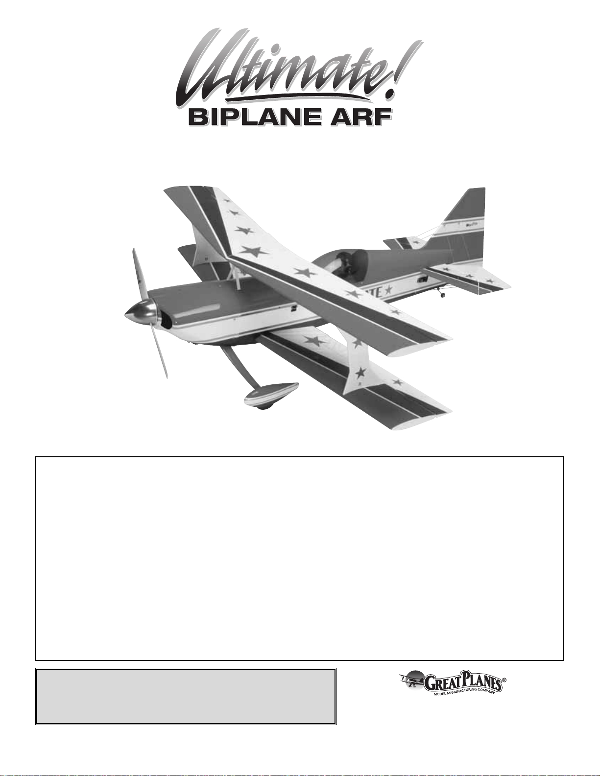
Wingspan: 65 in [1650mm]
Wing Area: 1446 sq in [93dm2]
Weight: 12 – 13.5 lb [5440 – 6120g]
Wing Loading: 19 – 22 oz/sq ft [58 – 67g/dm2]
Length: 72 in [1830mm]
Radio: 4-channel radio (minimum), 7-channel or greater computer
radio with mixing capabilities (preferred).
Engine: 1.60 cu in [26cc] two-stroke, 43cc gasoline engine
Page 2
2
INTRODUCTION ....................................................................2
AMA........................................................................................2
SAFETY PRECAUTIONS.......................................................2
DECISIONS YOU MUST MAKE.............................................3
Radio Equipment .............................................................3
Engine Recommendations ...............................................3
ADDITIONAL ITEMS REQUIRED..........................................4
Required Hardware & Accessories ..................................4
Optional Supplies & Tools................................................4
IMPORTANT BUILDING NOTES...........................................4
METRIC CONVERSIONS ......................................................5
ORDERING REPLACEMENT PARTS ...................................5
COMMON ABBREVIATIONS.................................................5
KIT INSPECTION...................................................................6
KIT CONTENTS.....................................................................6
PREPARATIONS....................................................................7
ASSEMBLE THE WINGS.......................................................7
Install the Ailerons ...........................................................7
Install the Aileron Servo & Pushrods...............................8
Join the Bottom Wing.......................................................9
Install the Center Cabanes & “I” Struts..........................11
Assemble the Top Wing.................................................13
Mount the Belly Pan.......................................................14
ASSEMBLE THE FUSELAGE .............................................14
Install the Elevators & Rudder.......................................15
Build the Carry Handle ..................................................15
Assemble the Landing Gear & Wheel Pants .................16
Install the Elevator & Rudder Servos.............................18
Install the Tail Wires.......................................................19
Install the Engine ...........................................................20
Install the Fuel Tank.......................................................23
Install the Cowl...............................................................24
Install the Receiver, Battery & Complete
the Aileron Connections.................................................25
FINISHING TOUCHES..........................................................27
Apply the Decals............................................................27
GET THE MODEL READY TO FLY ......................................27
Check the Control Directions.........................................27
Set the Control Throws..................................................27
Balance the Model (C.G.)..............................................28
Balance the Model Laterally ..........................................29
PREFLIGHT .........................................................................29
Identify Your Model.........................................................29
Charge the Batteries......................................................29
Balance the Propellers...................................................29
Ground Check ................................................................29
Range Check.................................................................29
ENGINE SAFETY PRECAUTIONS......................................30
AMA SAFETY CODE (excerpts).........................................30
General ..........................................................................30
Radio Control.................................................................30
CHECK LIST........................................................................31
FLYING .................................................................................31
Fuel Mixture Adjustments ..............................................31
Takeoff............................................................................32
Flight ..............................................................................32
Landing ..........................................................................32
FUJI-IMVAC BT-43 EIS ENGINE MOUNTING TEMPLATE.....33
O.S.
1.60 ENGINE MOUNTING TEMPLATE...................33
Any model called the “Ultimate” better be as good as it
sounds.The Great Planes Ultimate has been designed with
an eye on high performance and light weight. You will find
that there is not much this airplane cannot do.You are only
limited by your own abilities.We have no doubt that you too
will find it the “Ultimate” in model flying.
For the latest technical updates or manual corrections to the
“Ultimate” visit the Great Planes web site at
www.greatplanes.com. Open the “Airplanes” link, then
select the “Ultimate” ARF. If there is new technical
information or changes to this model a “tech notice” box will
appear in the upper left corner of the page.
We urge you to join the AMA (Academy of Model
Aeronautics) and a local R/C club.The AMA is the governing
body of model aviation and membership is required to fly at
AMA clubs.Though joining the AMA provides many benefits,
one of the primary reasons to join is liability protection.
Coverage is not limited to flying at contests or on the club
field. It even applies to flying at public demonstrations and
air shows. Failure to comply with the Safety Code (excerpts
printed in the back of the manual) may endanger insurance
coverage.Additionally, training prog r ams and instructors are
available at AMA club sites to help you get started the right
way. There are over 2,500 AMA chartered clubs across the
country. Contact the AMA at the address or toll-free phone
number below.
IMPORTANT!!! Two of the most important things you can do
to preserve the radio controlled aircraft hobby are to avoid
flying near full-scale aircraft and avoid flying near or over
groups of people.
1.Your “Ultimate” should not be considered a toy, but rather
a sophisticated, working model that functions very much like
PRO TECT YOUR MODEL,Y OURSELF
& OTHERS...FOLLOW THESE
IMPORTANT SAFETY PRECAUTIONS
Academy of Model Aeronautics
5151 East Memorial Drive
Muncie, IN 47302
Tele: (800) 435-9262
Fax (765) 741-0057
Or via the Internet at:
http://www.modelaircraft.org
AMA
INTRODUCTION
TABLE OF CONTENTS
Page 3

a full-size airplane. Because of its performance capabilities,
the “Ultimate,” if not assembled and operated correctly , could
possibly cause injury to yourself or spectators and damage
to property.
2. You must assemble the model according to the
instructions. Do not alter or modify the model, as doing so
may result in an unsafe or unflyable model. In a few cases
the instructions may differ slightly from the photos.In those
instances the written instructions should be considered
as correct.
3.You must take time to build straight, true and strong.
4. You must use an R/C radio system that is in first-class
condition, and a correctly sized engine and components
(fuel tank, wheels, etc.) throughout the building process.
5.You must correctly install all R/C and other components so
that the model operates correctly on the ground and in the air .
6.You must check the operation of the model before every
flight to insure that all equipment is operating and that the
model has remained structurally sound. Be sure to check
clevises or other connectors often and replace them if they
show any signs of wear or fatigue.
7. If you are not an experienced pilot or have not flown this
type of model before, we recommend that you get the
assistance of an experienced pilot in your R/C club for your
first flights.If you’ re not a member of a club, your local hob by
shop has information about clubs in your area whose
membership includes experienced pilots.
8. WARNING: The cowl and wheel pants included in this kit
are made of fiberglass, the fibers of which may cause eye,
skin and respiratory tract irritation. Never blow into a part
(wheel pant, cowl) to remove fiberglass dust, as the dust will
blow back into your eyes. Always wear safety goggles, a
particle mask and rubber gloves when grinding, drilling and
sanding fiberglass parts. Vacuum the parts and the work
area thoroughly after working with fiberglass parts.
Remember:Take your time and follow the instructions to
end up with a well-built model that is straight and true.
This is a partial list of items required to finish the “Ultimate”
that may require planning or decision making before starting
to build.
Radio:
4-channel radio (minimum), 7-channel or greater
computer radio with mixing capabilities (preferred).
Receiver:
4-channel minimum. 7 channel or greater (preferred).
Battery:
1000mAh (minimum)
Servos (IMAC type aerobatics):
Ailerons – four 50 oz-in servos
Elevator – two 50 oz-in servos
Rudder – one 100 oz-in servo or two 50 oz-in servos
Throttle – one 30 oz-in servo
Extreme and 3D aerobatics
Ailerons – four 75 oz-in servos
Elevator – two 75 oz-in servos
Rudder – one 130 oz-in servo or two 70 oz-in servos
Throttle – one 30 oz-in servo
Connectors:
Two “Y” harnesses.
Four 12" extensions.
Two or four 24" extensions.
The Great Planes “Ultimate” has been tested and flown with
the O.S. 1.60 cu in two-stroke [26cc] glow engine and the
Fuji-IMVAC BT-43EIS [43cc] gasoline engine. If you choose
another brand of engine, the following guidelines should
be followed.
1.5 – 1.8 cu in [25 – 30cc] two-stroke glow engine
1.8 – 2.1 cu in [30 – 36cc] four-stroke glow engine
1.9 – 2.6 cu in [32 – 43cc] gasoline engine
Note: The model was also tested with a DA50 gas engine
using a 20x8 prop.The model was considered over-pow ered
and will require throttle management for successful
operation. The use of engines weighing more than 2.5
pounds will require corresponding balancing tail weights and
will raise the all-up weight accordingly.
Engine Recommendations
Radio Equipment
DECISIONS YOU MUST MAKE
We, as the kit manuf acturer, provide you with a top quality ,
thoroughly tested kit and instructions, but ultimately the
quality and flyability of your finished model depends on
how you build it; therefore, we cannot in any way
guarantee the performance of your completed model, and
no representations are expressed or implied as to the
performance or safety of your completed model.
3
Page 4
This is the list of hardware and accessories required to finish
the “Ultimate.” Order numbers are provided in parentheses.
❏ 3' [900mm] Standard silicone fuel tubing (GPMQ4131)
❏ 2' [600mm] Large silicone fuel tubing (GPMQ4133)
❏ 3' [900mm] Gasoline fuel tubing (GPMQ4135)
❏ 1 oz. [30g] Thin Pro
™
CA (GPMR6002)
❏ 1 oz. [30g] Medium Pro CA+ (GPMR6008)
❏ Pro 30-minute epoxy (GPMR6047)
❏ Drill bits: 1/16" [1.6mm], 3/32" [2.4mm], 1/8" [3.2mm],
9/64" [3.6mm], 5/32" [4mm], 7/32" [5.6mm],
1/4" [6.4mm]
❏ 8-32 Tap
❏ #1 Hobby knife (HCAR0105)
❏ #11 Blades (5-pack, HCAR0211)
❏ Small T-pins (100, HCAR5100)
❏ Alcohol (for epoxy clean up)
❏ Masking tape
❏ Paper towels
❏ Flat file
Here is a list of optional tools mentioned in the manual that
will help you build the “Ultimate.”
❏ 2 oz. [57g] Spray CA activator (GPMR6035)
❏ R/C-56 canopy glue (JOZR5007)
❏ CA applicator tips (HCAR3780)
❏ CA debonder (GPMR6039)
❏ Epoxy brushes (6, GPMR8060)
❏ Mixing sticks (50, GPMR8055)
❏ Mixing cups (GPMR8056)
❏ Curved-tip canopy scissors for trimming plastic
parts (HCAR0667)
❏ Threadlocker
™
thread-locking cement (GPMR6060)
❏ Switch & Charge Jack Mounting Set (GPMM1000)
❏ Rotary tool such as Dremel
®
and cut-off wheel
❏ Dead Center
™
Engine Mount Hole Locator (GPMR8130)
❏ AccuThrow
™
Deflection Gauge (GPMR2405)
❏ CG Machine
™
(GPMR2400)
• There are three types of screws used in this kit:
• Sheet metal screws (SMS) are designated by a number
and a length. For example, #6 x 3/4" [19mm].
This is a number six screw that is 3/4" [19mm] long.
• Machine screws (MS) are designated by a number,
threads per inch, and a length. For example, 4-40 x
3/4" [19mm].
This is a number four screw that is 3/4" [19mm] long
with forty threads per inch.
• Socket-head cap screws (SHCS) are designated by a
number, threads per inch, and a length. For example,
4-40 x 1-1/2" [38mm].
This is a number four screw that is 1-1/2" [38mm] long
with forty threads per inch.
• When you see the term
test fit
in the instructions, it
means that you should first position the part on the
assembly without using any glue, then slightly modify or
custom fit
the part as necessar y for the best fit.
• Whenever the term
glue
is written you should rely upon
your experience to decide what type of glue to use.When a
specific type of adhesive works best for that step, the
instructions will make a recommendation.
• Whenever just
epoxy
is specified you may use either
30-minute (or 45-minute) epoxy or 6-minute epoxy. When
30-minute epoxy is specified, it is highly recommended that
you use only 30-minute (or 45-minute) epoxy, because you
will need the working time and/or the additional strength.
•
Photos
and
sketches
are placed before the step they
refer to. Frequently you can study photos in following steps
to get another view of the same parts.
• The “Ultimate” is factory-covered with Top Flite
®
MonoKote®film. Should repairs ever be required, MonoKote
can be patched with additional MonoKote purchased
separately. MonoKote is packaged in six-foot rolls, but some
hobby shops also sell it by the foot. If only a small piece of
MonoKote is needed for a minor patch, perhaps a fellow
modeler would give you some. MonoKote is applied with a
model airplane covering iron, but in an emergency a regular
iron could be used. A roll of MonoKote includes full
instructions for application.Following are the colors used on
this model and order numbers for six foot rolls.
White – TOPQ0204
Sapphire Blue – TOPQ0226
Missile Red – TOPQ0201
Metallic Gold – TOPQ0404
IMPORTANT BUILDING NOTES
Optional Supplies & Tools
Required Hardware & Accessories
ADDITIONAL ITEMS REQUIRED
4
Page 5

1" = 25.4mm (conversion factor)
Replacement parts for the Great Planes “Ultimate” ARF
are available using the order numbers in the
Replacement Parts List that follows. The fastest, most
economical service can be provided by your hobby
dealer or mail-order company.
To locate a hobby dealer, visit the Hobbico web site at
www.hobbico.com. Choose “Where to Buy”at the bottom of the
menu on the left side of the page.Follow the instructions provided
on the page to locate a U.S., Canadian or International dealer .If a
hobby shop is not available, replacement parts may also be
ordered from Tower Hobbies®at www.towerhobbies.com, or by
calling toll free (800) 637-6050.
Parts may also be ordered directly from Hobby Services by
calling (217) 398-0007, or via facsimile at (217) 398-7721,
but full retail prices and shipping and handling charges will
apply. Illinois and Nevada residents will also be charged
sales tax. If ordering via fax, include a Visa®or MasterCard
®
number and expiration date for payment.
Mail parts orders and payments by personal check to:
Hobby Services
3002 N. Apollo Drive, Suite 1
Champaign, IL 61822
Be certain to specify the order number exactly as listed in
the Replacement Parts List. Payment by credit card or
personal check only; no C.O.D.
If additional assistance is required for any reason, contact Product
Support by e-mail at productsupport@greatplanes.com, or by
telephone at (217) 398-8970.
Replacement Parts List
Order Number Description How to Purchase
Missing pieces Contact Product Support
Instruction manual Contact Product Support
Full-size plans Not available
GPMA2830 Bottom Wing Set Contact Hobby Supplier
GPMA2831 Top Wing Set Contact Hobby Supplier
GPMA2832 Fuselage Set Contact Hobby Supplier
GPMA2833 Tail Set Contact Hobby Supplier
GPMA2834 Cowl Contact Hobby Supplier
GPMA2835 Landing Gear Contact Hobby Supplier
GPMA2836 Wheel Pants (2) Contact Hobby Supplier
GPMA2837 Canopy Contact Hobby Supplier
GPMA2838 Tail Wheel Assembly Contact Hobby Supplier
GPMA2839 Aluminum Spinner Contact Hobby Supplier
GPMA2840 Interplane Struts (2) Contact Hobby Supplier
GPMA2841 Interplane Thumb Screws (4) Contact Hobby Supplier
GPMA2842 Cabane Struts (2) Contact Hobby Supplier
GPMA2843 Decal Set Contact Hobby Supplier
GPMA2844 Flying Wire Set Contact Hobby Supplier
Fuse = Fuselage
Stab = Horizontal Stabilizer
Fin = Ver tical Fin
LE = Leading Edge
TE = Trailing Edge
LG = Landing Gear
Ply = Plywood
" = Inches
mm = Millimeters
SHCS = Socket-Head Cap Screw
COMMON ABBREVIATIONS
ORDERING REPLACEMENT PARTS
METRIC CONVERSIONS
5
1/64" = .4 mm
1/32" = .8 mm
1/16" = 1.6 mm
3/32" = 2.4 mm
1/8" = 3.2 mm
5/32" = 4.0 mm
3/16" = 4.8 mm
1/4" = 6.4 mm
3/8" = 9.5 mm
1/2" = 12.7 mm
5/8" = 15.9 mm
3/4" = 19.0 mm
1" = 25.4 mm
2" = 50.8 mm
3" = 76.2 mm
6" = 152.4 mm
12" = 304.8 mm
18" = 457.2 mm
21" = 533.4 mm
24" = 609.6 mm
30" = 762.0 mm
36" = 914.4 mm
Page 6
6
Before starting to build, take an inventory of this kit to make sure it is complete, and inspect the parts to make sure they
are of acceptable quality. If any parts are missing or are not of acceptable quality, or if you need assistance with assembly,
contact Product Support. When reporting defective or missing parts, use the part names exactly as they are written in
the Kit Contents list.
Great Planes Product Support
3002 N. Apollo Drive, Suite 1
Champaign, IL 61822
Telephone: (217) 398-8970, ext. 5
Fax:(217) 398-7721
E-mail: airsupport@greatplanes.com
KIT INSPECTION
Description Quantity
Wire Clip 4
120-180 Engine Mount Left 1
120-180 Engine Mount Right 1
4-40 Threaded Metal Clevis 8
4-40 Solder Clevis 8
3/16" x 2" Axles 2
Screw-Lock Pushrod Connector 2
4-40 Blind Nuts 10
4-40 Nut 8
6-32 Blind Nuts 6
8-32 Blind Nuts 4
5/16-24 Lock Nut 2
1/4-20 Blind Nut 2
4-40 Nylon Lock Nut 10
1/4-20 Nylon Bolt 2
Large Black Control Horn 8
Nylon Retainer 2
2" x 9" Hinge Material 2
11-3/4" Gray Plastic Outer Tube 1
Clevis Keeper 16
#4 x 1/2" SMS 33
#2 x 3/8" SMS 8
4-40 x 3/8" Machine Screw 4
6-32 x 1/2" SHCS 4
4-40 x 1" SHCS 4
4-40 x 1/2" SHCS 4
4-40 x 3/4" SHCS 4
4-40 x 1/2" Machine Screw 4
6-32 x 1" SHCS 6
8-32 x 1-1/4" SHCS 4
8-32 x 1" SHCS 4
4-40 x 1/8" SHCS 2
3/16" Wheel Collar 4
.074 x 12" Wire Threaded One End 1
.095 X 5-3/4" Wire Threaded One End 4
.095 X 12" Wire Threaded One End 3
4-40 Lock Washer 12
#6 Flat Washer 6
#4 Flat Washer 17
#2 Flat Washer 8
#8 Lock Washer 8
#8 Flat Washer 8
#6 Lock Washer 6
2-56 x 5/8" Machine Screw
#64 Rubber Bands 2
Aluminum Knurled Knobs 4
8-32 x 2" Threaded Rod 4
Aluminum Engine Stand-offs 4
Flying Wire Hardware 1 set
Spinner Nut 1
Spinner Bolt 1
Aluminum Rib 1
Kit Contents (Not Photographed)
KIT CONTENTS
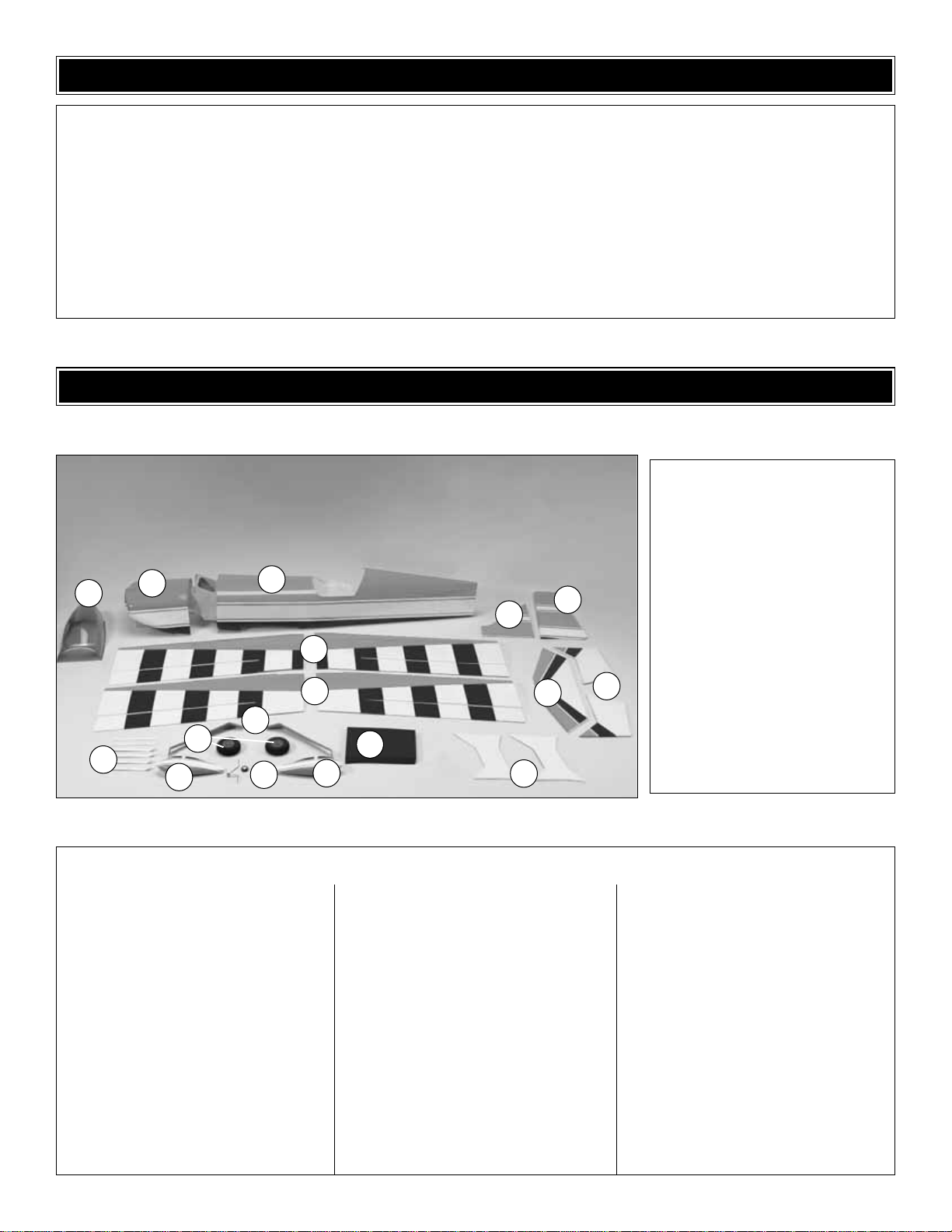
Kit Contents
1. Canopy
2. Cowl
3. Fuselage
4. T op Wing Halves (L&R)
5. Bottom Wing Halves (L&R)
6. Fin
7. Rudder
8. Cabanes (6)
9. Main Landing Gear
10. Main Wheels (2)
11. Wheel Pants (L&R)
12. T ail Wheel Assembly
13. Belly Pan
14. Inter plane Struts (2)
15. Horizontal Stabilizer
16. Elevators (L&R)
1
5
4
3
12
13
15
16
14
11
11
7
8
9
6
2
10
Page 7
❏ 1. If you have not done so already, remove the major
parts of the kit from the box and inspect for damage. If any
parts are damaged or missing, contact Product Suppor t at
the address or telephone number listed in the
“Kit
Inspection”
section on page 6.
❏ 2. Remove the tape and separate the ailerons and flaps
from the wing and the elevators from the stab. Use a
covering iron with a covering soc k on high heat to tighten the
covering if necessary.Apply pressure over sheeted areas to
thoroughly bond the covering to the wood.
Do the bottom right wing first so your work matc hes the
photos the first time through.
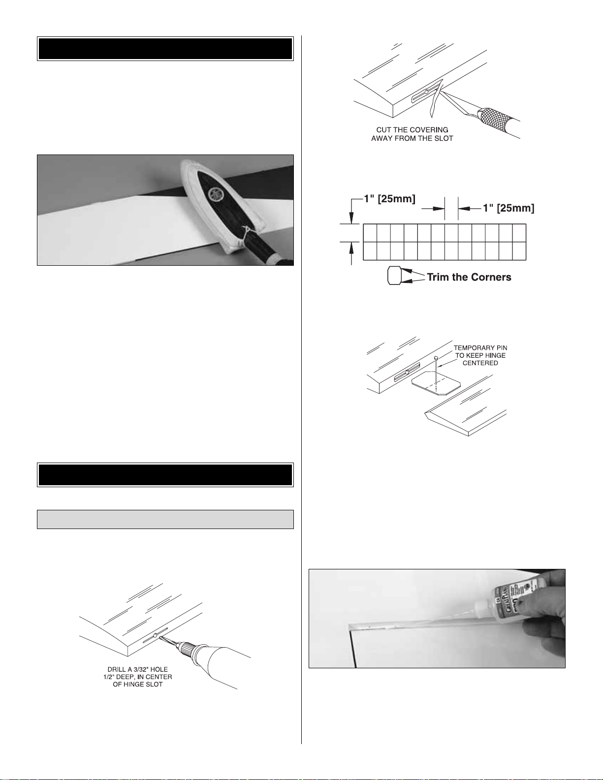
❏ ❏ ❏ ❏ 1. Drill a 3/32" [2.4mm] hole, 1/2" [13mm] deep
in the center of each hinge slot to allow the CA to “wick” in.
Follow-up with a #11 blade to clean out the slots .Hint: If you
have one, use a high-speed rotary tool to drill the holes.
❏ ❏ ❏ ❏ 2.Use a sharp #11 blade to cut a strip of covering
from the hinge slots in the wing and aileron.
❏ 3. Cut sixteen 1" x 1" [25 x 25mm] hinges from a CA
hinge strip. Snip off the cor ners so they go in easier.
❏ ❏ ❏ ❏ 4. Test fit the ailerons to the wing with the
hinges. If the hinges don’t remain centered, stick a pin
through the middle of the hinge to hold it in position.
❏ ❏ ❏ ❏ 5.Remove any pins y ou ma y ha v e inserted into
the hinges. Adjust the aileron so there is a small gap
between the LE of the aileron and the wing.The gap should
be small, just enough to see light through or to slip a piece
of paper through.
❏ ❏ ❏ ❏ 6.Apply six drops of thin CA to the top and bottom
of each hinge. Do not use CA accelerator. After the CA has
fully hardened, test the hinges by pulling on the aileron.
❏ 7. Repeat steps 1 to 6 for the left wing panel and the two
wing panels for the top wing.
Install the Ailerons
ASSEMBLE THE WINGS
PREPARATIONS
7
Page 8
❏ ❏ ❏ ❏ 1. Cut away the covering from the servo bay in
the bottom of the bottom right wing panel.Turn the wing ov er
and cut the covering from the hole in the top of the wing at
the wing root.
❏ ❏ ❏ ❏ 2. Inside the servo bay a string is taped.
Carefully remove the string from the servo bay and tape it to
the outside of the wing to prevent it from dropping back into
the wing.The other end of the string is taped to the root rib.
Remove the tape, thread the string through the small holes
you cut the covering from on the bottom of the wing, and
tape the string to the wing.
❏ ❏ ❏ ❏ 3. Install a 12" [305mm] servo extension onto
the servo lead. Secure the extension to the lead with tape, a
piece of shrink tube or some other method to keep them
from coming unplugged.
❏ ❏ ❏ ❏ 4.Tie the string to the servo extension.Pull the
string and the servo lead through the wing. Untie the string
from the lead and insert the lead through the small hole you
cut the covering from.Tape the lead to the wing to prevent it
from falling back into the wing.
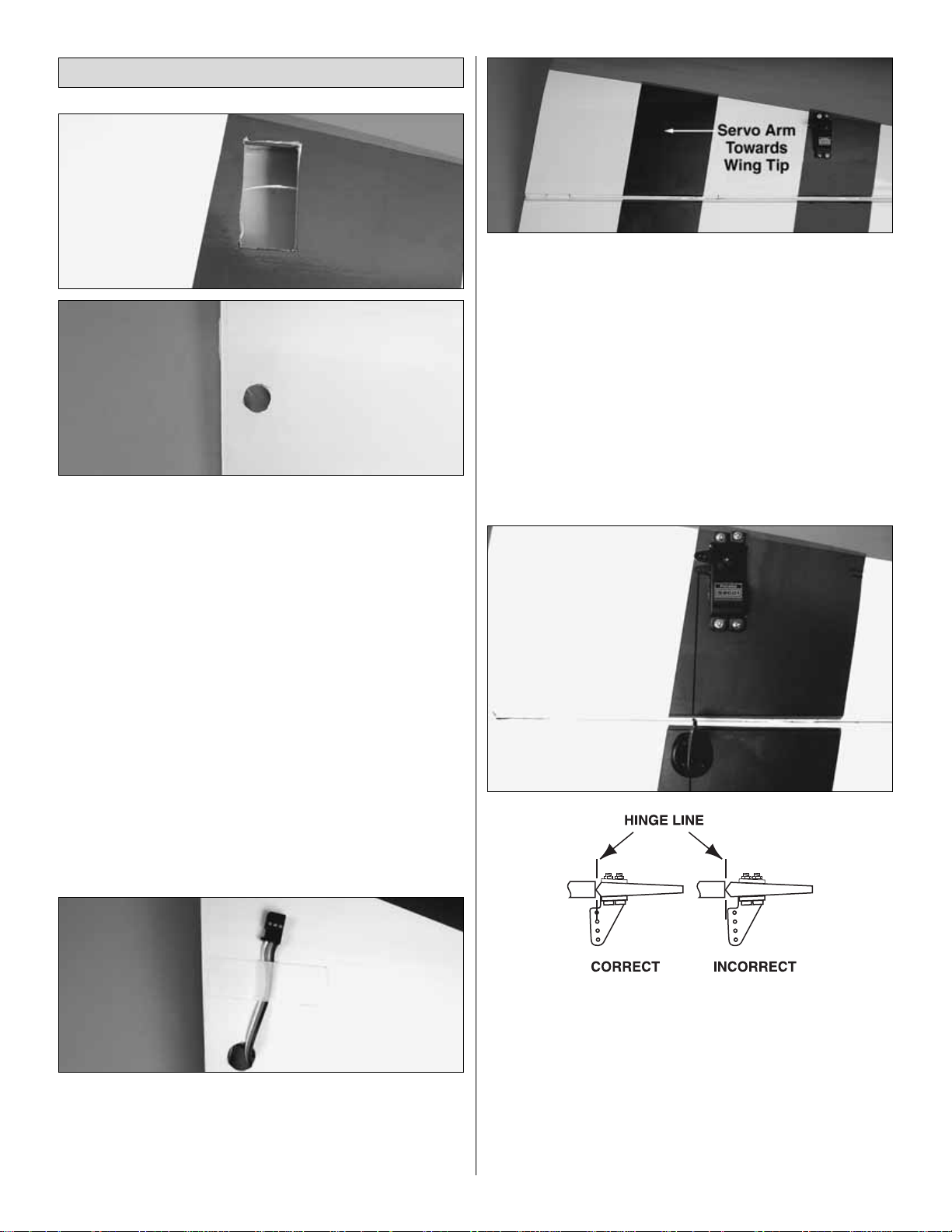
❏ ❏ ❏ ❏ 5. Install the servo into the servo opening. Drill
through the servo mounting holes with a 1/16" [1.6mm] drill
bit. Remove the servo from the servo opening. Install and
then remove a servo mounting screw into each of the holes
you have drilled. Apply a drop of thin CA into the holes to
harden the threads. Once the glue has cured, install the
servo into the servo opening using the hardware included
with your servo.Center the servo then install a servo arm as
shown.The arm should be pointing towards the wing tip.
❏ ❏ ❏ ❏ 6. Place a nylon control horn in line with the
outer hole in the servo arm. When positioned properly, the
control horn will rest on a hardwood plate in the aileron.
Mark the location of the mounting holes onto the aileron.
Drill a 3/32" [2.4mm] hole on the marks, drilling through the
plywood plate
but not
through the top of the aileron. Insert
and remove a #4 x 1/2" [13mm] screw into each of the holes .
Apply a couple drops of thin CA into the holes to harden the
threads. Once the glue has hardened attach the horn to the
aileron with four #4 x 1/2" [13mm] screws.
Install the Aileron Servos & Pushrods
8
Page 9
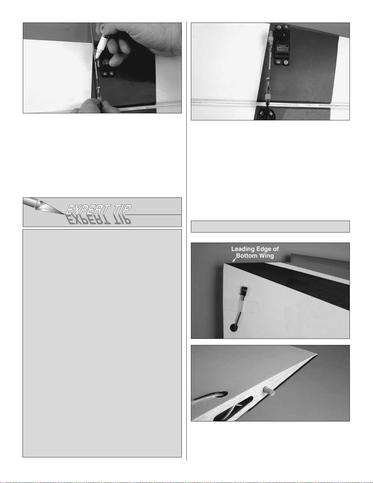
❏ ❏ ❏ ❏ 7.Thread a 4-40 nut onto a 4-40 x 5-3/4" [146mm]
threaded rod approximately twenty turns.Slide a silicone clevis
retainer onto a threaded 4-40 metal clevis. Then, thread the
clevis onto the rod, tightening it against the nut. Install the
clevis onto the nylon control horn. Install an unthreaded clevis
onto the servo arm. Center the aileron and then mark the
threaded rod where it should be cut to fit the clevis.Remove all
of the pushrod components from the servo and control horn.
Read the
Expert Tip
that follows and then silver solder the
clevis to the pushrod.
❏ ❏ ❏ ❏ 8. After the rod has cooled, install a clevis
retainer onto the clevis you have just soldered.Then, install
the pushrod onto the aileron and servo.
❏ 9. Repeat steps 1-8 for the left wing panel. Repeat steps
1-8 for the top wing panels.Note: When cutting the covering
from the hole in the top wing for the servo lead, the hole is
located on the bottom-middle of the wing.
❏ 1. Epoxy a 3/16" x 1" [4.8 x 25mm] hardwood dowel into
the root rib of the bottom right wing panel. (Note: The
bottom wing can be identified by the set back at the wing
center-section). The dowel should extend 1/2" [13mm] into
the hole in the wing.
Join the Bottom Wing
How to solder
A. Use denatured alcohol or other solvent to thoroughly
clean the pushrod. Use coarse sandpaper to roughen the
end of the pushrod where it is to be soldered.
B. Apply a few drops of soldering flux to the end of the
pushrod. Then, use a soldering iron or a torch to heat it.
Tin the heated area with silver solder (GPMR8070) by
applying the solder to the end. The heat of the pushrod
should melt the solder–not the flame of the torch or
soldering iron–thus allowing the solder to flow.The end of
the wire should be coated with solder all the way around.
C.Place the clevis on the end of the pushrod. Add another
drop of flux. Then, simultaneously heat the clevis and
pushrod. Slide the clevis the rest of the way onto the
pushrod as the solder melts. Apply another small amount
of solder while the pushrod and clevis are still hot. The
same as before, the heat of the parts being soldered
should melt the solder, thus allowing it to flow. Allow the
joint to cool naturally without disturbing. Avoid excess
blobs, but make certain the joint is thoroughly soldered.
The solder should be shiny, not rough. If necessary,
reheat the joint and allow to cool.
D. Immediately after the solder has solidified, but while it
is still hot, carefully use a cloth to quickly wipe off the flux
before it hardens. Important: After the joint cools, coat
with oil to prevent rust.Note: Do not use the acid flux that
comes with silver solder for electrical soldering.
9
Page 10
❏ 2. Test fit the plywood and balsa wing joiner into the
joiner pocket of both wing halves. When you are satisfied
with the fit of the joiners, glue the joiner into the bottom wing
panels with 30-minute epoxy. When gluing the wing panels
together, be sure to get glue into the joiner pockets in the
wing.This can be done by applying the glue into the pocket
with a small stick.Apply glue to the pocket, the joiner and the
root rib of the wing.
❏ 4. Hold the wing together while the glue is curing with
masking tape. Be sure that both of the root ribs are pulled
tightly against one another. Excess epoxy can be cleaned
away with rubbing alcohol and a paper towel.
❏ 5. Epoxy two 3/8" x 1-1/4" [9.5 x 32mm] hardwood
leading edge dowels into the two holes in the front of the
wing.The dowel should extend 1/2" [13mm] from the front of
the wing. Set the wing aside until the glue fully hardens.
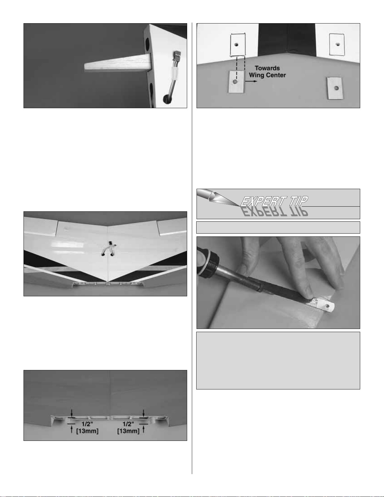
❏ 6. Place the plywood wing bolt mounting plates in
position on the bottom of the wing, over the wing bolt holes.
When positioning the plates be sure the widest part of the
plate is towards the center of the wing. Using a fine tip
marker, trace the outline of the plate onto the wing. Use a
sharp #11 hobby knife or refer to the
Expert Tip
that follows
to cut the covering from the wing along the lines you have
marked.Use care to cut only into the coveringand notinto
the wood.
❏ 7. Glue the plates in position onto the wing.
Use a soldering iron to cut the covering from a balsa
sheeted surface.The tip of the soldering iron doesn’t have
to be sharp, but a fine tip does work best.Allow the iron to
heat fully.Use a straightedge to guide the soldering iron at
a rate that will just melt the covering and not burn into the
wood. The hotter the soldering iron, the faster it must
travel to melt a fine cut.Peel off the covering.
How to cut covering from balsa
10
Page 11
❏ 1. Cut the covering away from the openings in the top of
the fuselage as well as the covering away from the holes
located on both sides of the front of the fuselage.
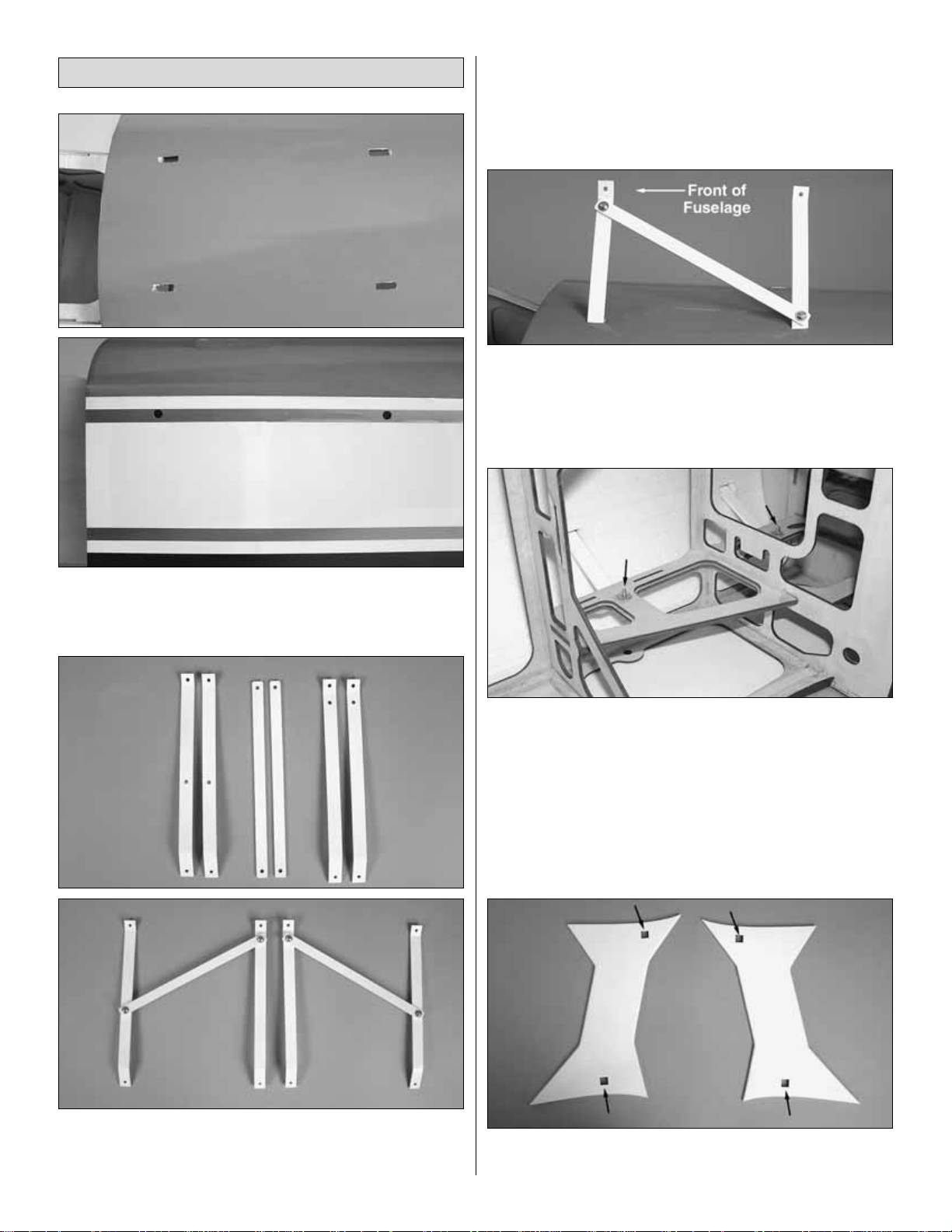
❏ 2. Identify the parts of the cabanes. Assemble them as
shown with 4-40 x 3/8" [9.5mm] machine screws, #4 flat
washers and 4-40 nylon lock nuts. When assembling the
cabanes apply a couple of drops of Threadlocker to the
screws.Do not fully tighten the screws;just make them snug
for now.
❏ 3. Inser t the cabane for the left side of the fuselage into
the slots on the top, left side of the fuselage. Be sure the
cabane slides into the slots located inside of the fuselage.
❏ 4.Located inside the fuselage are 4-40 blind nuts.Align the
holes in the cabanes with the blind nuts.Mount the cabanes to
the fuselage with 4-40 x 1/2" [13mm] socket-head cap screws
and #4 lock washers.Apply a couple of drops of Threadlocker
onto the screws. Install the screws through the holes you cut
the covering from on the sides of the fuselage. Do this for all
four of the cabane legs. Tighten all of the screws for the
cabane assembly and the mounting screws.
❏ 5. Cut the covering from the openings on both of the
“I” struts.
Install the Center Cabanes & “I”Struts
11
Page 12

❏ ❏ ❏ ❏ 6. Locate one of the knurled knobs and an
8-32 x 2" [51mm] threaded rod.
❏ ❏ ❏ ❏ 7. Inser t the knurled knob into the opening on
one end of the “I” strut.
❏ ❏ ❏ ❏ 8. On each end of the “I” strut, cut the covering
from the hole and insert the threaded rod into the hole in the
bottom of the strut, threading the rod into the knurled knob.
(The threaded rod should slip easily into the strut. If not, drill
through the hole with a 5/32" [4mm] drill bit).Thread the rod
into the knob until the threaded rod is flush with the face of
the knob.
❏ ❏ ❏ ❏ 9. Carefully apply a couple of drops of thin CA
to the threads of the rod and knob.This is best done with a
micro tip on the bottle of CA. Only a couple of drops are
required to satisfactorily bond the rod and knob together.
❏ 10. Repeat steps 6-9 for each of the knurled knobs and
threaded rods, completing the assembly for each of the
openings in the “I” struts.
❏ 11. Glue a 1/8" x 1" [3 x 25mm] dowel into each of the
holes in the bottom of the “I” Struts. Approximately 3/8"
[9.5mm] of the dowel should extend from the strut.
❏ 12. On the top of the bottom wing and the bottom of the
top wing you will find two pin holes located approximately 9"
12
Page 13

[230mm] from the wing tips. Cut the covering away from
these holes.
❏ 13. Mount the bottom wing to the fuselage with two
1/4-20 x 2" [51mm] wing bolts.
❏ 14. Using the knurled knob as a thumb screw, thread the
cabane into the blind nut in the wing and align the wood
dowel with the hole in the wing. Install the “I” str uts onto the
bottom wing.
❏ 1. Glue the two 3/8" x 1" [9.5 x 25mm] wood dowels into
the holes located in the root rib of the right wing panel of the
top wing.
❏ 2. Locate the aluminum wing r ib.Test fit the components
of the top wing by sliding the aluminum rib onto the dowels
in the right wing panel. (Be sure that the tongue from the
aluminum rib is toward the bottom of the wing). Inser t the
balsa and plywood wing joiner into the joiner pocket and
then slide the left wing panel onto the right wing panel.
Check to be sure that the root rib of the wings makes solid
contact with the aluminum rib. If they do not make good
contact with each other, sand a small amount off of the wing
dowels.This will allow the wings to slide together completely.
When you are satisfied with the fit, disassemble the wing.
Glue the top wing together with 30-minute epoxy using the
same method used for the bottom wing. Move quickly to
the next step before the epoxy hardens.
❏ 3. Mount the top wing to the “I” struts using the thumb
screws. When placing the wing, be sure the small dowels
align with the hole in the wing and the aluminum joiner drops
between the cabane struts.Tighten the wing to the “I” struts.
Assemble the Top Wing
13
Page 14

❏ 4. Once the wing is attached to the struts, install a 4-40
x 1/2" [13mm] socket-head cap screw into the cabane
mounting holes. Set the fuselage and wing assembly aside
until the glue has fully hardened.
❏ 1. Cut the covering away from the wing bolt holes on the
bottom of the belly pan.
❏ 2. Place the belly pan on the bottom wing, positioning it
over the wing bolts.Trace the outline of the belly pan onto
the bottom wing.
❏ 3.Cut the covering from the fuselage inside the lines you
have drawn on the wing.Use the same technique for cutting
the covering as used for the wing bolt plates. Glue the belly
pan to the wing.
❏ 1. If you have removed the wings, re-install them to the
fuselage. Cut the covering from the back of the fuselage to
reveal the slot f or the horizontal stabilizer and the v ertical fin.
❏ 2. Slide the horizontal stabilizer into the slot in the
fuselage. Stand back and look at the stab in relation to the
wing.The stab should be parallel with the wing. If not, sand
the stab saddle until the stab and wings are aligned.
❏ 3.Measure the distance from the tip of the stab to the tip of
each wing. Adjust the position of the stab until they are equal.
❏ 4. Using a fine-point felt-tip pen, mark the outline of the
fuselage on the top and the bottom of the stab.
❏ 5. Cut the covering on the top and bottom of the stab
inside the line you have drawn. Use the same technique for
cutting the covering as used for the wing bolt plates and the
belly pan, cutting along the lines you have mark ed.Use care
to cut only into the covering and not into the wood.
ASSEMBLE THE FUSELAGE
Mount the Belly Pan
14
Page 15

❏ 6. Glue the stab in place making sure that the stab is
properly aligned. Allow the glue to harden before continuing
with step #7.
❏ 7. Insert the vertical fin into the slot at the rear of the
fuselage. Mark the outline of the fuselage to the fin. Cut the
covering from the fin and glue the fin in place, making sure it is
perpendicular to the stab.If needed, hold the fin in position with
masking tape to assure that the fin remains perpendicular.
You can now remove the wings and continue with the
assembly of the fuselage.
❏ 1.Using the same installation method used for the ailerons,
install three 1" x 1" [25 x 25mm] hinges into each elevator half
and then install the elevators into the stab. Glue the hinges
using thin CA.
❏ 2. Glue four hinges to the fin and rudder with thin CA.
This kit comes with a convenient carrying handle for the
fuselage. In addition to its use as a handle, when installed,
it will allow you to turn the plane upside-down on the
workbench without flexing or bending the center cabanes.
❏ 1.Locate all of the 1/8" [3mm] plywood parts of the handle.
❏ 2. Glue the five parts together in the sequence shown.
Build the Carry Handle
Install the Elevators & Rudder
15
Page 16

❏ 3.When properly assembled, f our slots are formed in the
handle as shown.
❏ 4.Install two 4-40 blind nuts into the holes on one side of
the handle.
❏ 5. Position the handle onto the cabane. Fasten the
handle to the cabane with two 4-40 x 3/4" [19mm] sockethead cap screws and #4 washers.
❏ 1. Bolt the landing gear to the fuselage with 6-32 x 1"
[25mm] socket-head cap screws, #6 lock washers and #6
flat washers. When installing the landing gear, be sure the
gear sweeps towards the back of the fuselage.
❏ 2. Cut the axles to a length of 1-5/8" [41mm].
❏ 3. Install the axles to the landing gear with the axle nuts.
❏ 4. File a flat spot onto the end of the axles.
Assemble the Landing Gear & Wheel Pants
16
Page 17

❏ ❏ 5. Apply a couple of drops of threadlocker onto two
6-32 x 1/4 [6mm] socket-head cap screws. Then, thread
them in the 3/32" [2.4mm] wheel collars.Slide a wheel collar
onto the axle followed by a wheel and the remaining wheel
collar. Tighten the wheel collars. Be sure the wheel rolls
freely. Do this for both wheels.
❏ ❏ 6.Slide the wheel pant over the wheel.Apply a couple
of drops of Threadlocker to the screws and then fasten the
wheel pant to the landing gear with two 4-40 x 1/2" [13mm]
machine screws, #4 lock washers and #4 flat washers.
Repeat this for the remaining wheel.
❏ 7. Cut the covering from the hole located at the bottom
rear of the fuselage.
❏ 8. Locate the nylon tail wheel bushing and glue it in place
in the hole.
❏ 9. Slide the aluminum wheel collar (included in the tail
wheel hardware bag) onto the tail wheel wire and secure it
with the set screw. Inser t the tail wheel assembly into the
nylon bearing. Position the aluminum bracket to hold the tail
wheel assembly to the fuselage. Drill two 1/16" [1.6mm]
holes through the bracket, into the fuselage. Attach the
bracket to the fuselage with two #2 washer head screws.
❏ 10. Slide the nylon retainer onto the tail wheel wire.
❏ 11. Drill a 1/8" [3mm] hole into the bottom of the rudder.
Center the hole at the mid point of the bottom of the rudder.
❏ 12.Glue the nylon retainer into the hole, making sure the
tail wheel wire is in the nylon retainer.
17
Page 18

This airplane has been designed to utilize two servos for the
elevator with a minimum torque of 54 oz. in. each. The
rudder can utilize either one or two servos with a total torque
output of at least 100 oz. in.
❏ 1.Cut the covering away from the openings in the rear of
the fuselage for the elev ator and rudder servos.The elevator
servos are located in the upper servo openings.The rudder
servos are in the lower servo openings. When cutting the
covering away for the rudder, only cut out the covering for
the number of servos you will be using. It does not matter
into which side of the fuselage you choose to install the
rudder servo.
❏ 2.Install a 24" [610mm] servo extension onto each of the
servo leads. Secure the extension to the lead with tape, a
piece of shrink tube or some other method to keep them
from coming unplugged.
❏ 3. Install the elevator and rudder servos into the servo
openings. Drill through the servo mounting holes with a
1/16" [1.6mm] drill bit. Remove the servo from the servo
opening. Install and then remove a servo mounting screw
into each of the holes you have drilled. Apply a drop of thin
CA into the holes to harden the threads. Once the glue has
hardened, install the servo into the servo opening using the
hardware included with your servo. Center the servo and
then install a servo arm as shown. If you want to achieve 3D
throws we recommend the use of longer servo arms. The
Great Planes 1-1/2" [38mm] aluminum servo arm
(GPMM1105) works well for this.
❏ 4.Place a nylon control horn in line with the outer hole in
the servo arm. When positioned properly, the control horn
will rest on a hardwood plate in the elevator. Mark the
location of the mounting holes onto the elevator.Drill a 3/32"
[2.5mm] hole on the marks, drilling through the plywood
plate
but not
through the top of the elevator. Insert and
remove a #4 x 1/2" [13mm] screw into each of the holes.
Apply a couple drops of thin CA into the holes to harden the
threads. Once the glue has hardened, attach the control
horn to the elevator with two #4 x 1/2" [13mm] screws.
❏ 5. Repeat this procedure for the rudder servo/servos. If
you are installing two rudder servos, the rudder control
horns will be opposite each other, making it difficult to mount
them with the #4 screws.Instead mount the control horns to
the rudder with four #4 x 1" [25mm] socket-head cap scre ws
and four 4-40 lock nuts as shown in the sketch.
❏ 6.Thread a 4-40 nut onto a 4-40 x 12" [305mm] threaded
rod approximately twenty turns. Slide a silicone clevis
retainer onto a threaded 4-40 metal clevis.Then, thread the
clevis onto the rod, tightening it against the nut. Install the
clevis onto the nylon control horn. Install an unthreaded
solder clevis onto the servo arm.Center the elevator and the
servo. Next, mark the position the wire should be cut to fit
into the solder clevis. Remove all of the pushrod
components from the servo and control horn. Cut the wire
and on the mark and then solder the clevis to the wire.
❏ 7. After the rod has cooled, install a clevis retainer onto
the clevis you have just soldered. Install the pushrod onto
Install the Elevator & Rudder Servos
18
Page 19

the elevator and servo. Follow the same procedure for the
rudder pushrod.
❏ 8. Using the same method, install the pushrod linkage to
the opposite elevator and the rudder (if a second rudder is
to be used).
The tail wires are a functional component of this aircraft.DO
NOT fly the plane without the wires.
❏ 1.Examine this sketch closely.It shows the assembly of the
tail wire attachment posts.The parts are bagged together and
are pre-assembled.You can see that the wire threads through
the holes in the post and is retained by the set screw and the
small steel ball.
You will be able to assemble the wires without
taking the components of the post apart. If you find a need to
disassemble the post be very careful not to let any of the
parts fall out where you will not be able to find them.The ball
and set screw are very small! Four extra balls are included in
the bag.There is no need to disassemble the post to assemble
the flying wires! These are extras in case you should e ver lose
one in the assembly.
Do not install the wires without the ball! If you simply tighten
the set screw against the wire it will eventually break the wire!
❏ 2. The location of the wire attachment points are located
with a pin hole in the stab and fin. Cut the covering to reveal
the mounting holes. Insert a 2-56 x 5/8" [16mm] machine
screw and #2 flat washer into one of the pre-assembled
wires. Insert the screw, washer and wire into the forward
hole in the fin. On the other side of the fin, inser t another
wire over the screw followed by another #2 washer and a
2-56 nut. It is a good idea to apply a drop of Threadlocker to
the threads of the screw before installing the nut.Tighten the
nut to the screw but do not overtighten it, crushing the
wood. Repeat this step for the rear hole in the fin.
❏ 3. Holes for the wire attachment hardware are indicated
by pin hole on the stab.Locate the hole and then run a 5/32"
[4mm] drill bit through the holes.Do this for both of the holes
on each half of the stab. Install a post into one of the holes
located in the stab. Slide the retainer clip over the post on
the bottom of the stab, pushing it snugly against the bottom
of the stab.
❏ 4. Loosen the set screw. Slide the wire through the hole
in the post and under the ball located in the post. Without
removing the set screw, apply a small amount of
Threadlocker onto the threads of the set screw. Do not
tighten the wire yet; just lightly tighten the set screw to hold
the wire in the post. Do this for all four of the posts.
❏ 5. Inser t the remaining four wires into the holes in the
bottom of the posts using the same procedure used on the
top of the stab.
Install the Tail Wires
19
Page 20

❏ 6.Located on the bottom of the fuselage are two plywood
plates.Drill a 1/16" [1.6mm] hole in the center of each of the
plates. Install a #2 x 3/8" [9.5mm] screw and a #2 washer
through the end of the wire from the left and right side of the
stab. Thread the screw into the plate. Repeat this for the
remaining wire.
❏ 7. Proceed to loosen the set screw enough to allow the
wire to be pulled through the post. Lightly tension each wire
before re-tightening the set screw. The wires do not need to
be overly tight; snug is adequate. When you are satisfied
with the tension of the wires, cut the excess wire
approximately 1/4" [6mm] from the post. This will allow
enough wire to grab onto with pliers should you e v er need to
make further adjustments.
If you are installing a brand of glow engine other than the
O.S.®, read through the installation instructions for the O.S.
1.60. The procedure should be similar. The most impor tant
thing is to be sure to follow the spacing dimensions from the
engine drive washer back to the firewall
If you are installing the Fuji-IMV A C™BT-43 EIS or other gasoline
engine, skip ahead to the instructions for mounting that engine.
If you will be using another brand of gasoline engine, read
through the installation instructions for the Fuji-IMVAC. You
should find the mounting instructions for the Fuji-IMVAC helpful
in determining the best way to mount your particular brand of
engine.Skip to page 21 for gas engine installation.
Installation instructions for the O.S.1.60 two-cycle engine
❏ 1. On page 33 of this manual you will find the engine
mounting template for the O.S. 1.60 engine. Cut out the
template from the manual and tape it to the firewall, aligning
the lines of the template with the lines on the firewall.
❏ 2. On each of the four marks drill a 7/32" [5.6mm] hole.
Install an 8-32 blind nut into each of the holes from the back
of the firewall. Install a #8 flat washer onto a 8-32 x 1"
[25mm] socket-head cap screw. Then, tighten the screw into
the blind nut, pulling it into the firewall
❏ 3.Cut the tabs from the engine mount. Install the engine
mount to the firewall with four 8-32 x 1-1/4" [32mm] sockethead cap screws, #8 flat washers and #8 lock washers.
When installing the mount, be sure that you have the mount
positioned allowing the engine to be mounted on its side.
Install the Engine
20
Page 21

❏ 4. Position the engine on the mount so the distance from
the firewall to the front of the thrust washer measures 7"
[178mm]. Mark the location of the engine on the mount.The
Great Planes “Dead Center™” Hole Locator (GPMR8130)
works well for this. Dr ill through the marks you have made
with a #29 or 9/64" [3.6mm] drill bit. Tap each hole with an
8-32 tap.
❏ 5. Install the engine to the mount with four each, 8-32 x
1" [25mm] socket-head cap screws , #8 lock washers and #8
flat washers.
❏ 6. Install the muffler onto the engine. Next, install the
throttle servo into the servo opening on the side of the
firewall box. Drill a 1/16" [1.6mm] hole through each of the
mounting holes. Remove the servo and then install and
remove a servo mounting screw into each hole. Apply a
couple drops of thin CA into the holes to harden the threads.
When the glue has cured permanently, mount the servo.
❏ 7. Install a brass screw-lock pushrod connector, nylon
retainer ring and a 4-40 x 1/4" [6mm] socket-head cap screw
onto the outer hole of the servo arm and the throttle servo
arm. Bend a .074 x 12" [305mm] threaded rod to fit from the
throttle servo arm to the throttle arm.When bending the wire
be sure that you have clearance between the pushrod and
any of the engine/muffler components. Metal contact may
create radio interference.
End of glow engine installation. Skip to page 23.
Installation instructions for the Fuji-IMVA C BT-43 EIS (or
other brands of gasoline engines)
The following instructions are specific to the Fuji-IMVAC
BT-43 EIS. Other gasoline engines may be able to use a
mounting procedure very similar to the Fuji-IMV A C so tak e a
minute to review these engine mounting instructions. Pay
close attention the dimensions for spacing the engine from
the firewall when mounting your particular brand of engine
and be sure to use the mounting template for your particular
brand of engine.
(Please Note: The mounting hardware and pushrods for the
installation of a gasoline engine are not included in the kit.
All of the bolts and pushrods are readily available at the local
hobby shop).
❏ 1.Mark a line on the both sides of the engine box centering
the line on the firewall tabs. Measure up from the tabs 1/2"
[13mm] and make a crossing line. Dr ill a 1/8" [3mm] hole on
the marks, drilling into the firewall approximately 1/2" [13mm].
21
Page 22

❏ 2. Locate the 1/8" x 6" [3 x 152mm] hardwood dowel.
Apply epoxy into the holes and on the dowel. Insert the
hardwood dowel into the hole. Cut the dowel flush with the
surface. Do this for all four holes. Apply a few drops of thin
CA to fuelproof the ends of the dowels.
❏ 3.Cut out the Fuji-IMVAC BT-43 EIS mounting template from
page 33 of this instruction manual. Tape the template, aligning
the marks on the template with the lines on the firewall.
❏ 4. Drill a 1/4" [6mm] hole through each of the marks on
the template. Insert a 10/24 [5mm] blind nut into the holes
from the back of the firewall.
❏ 5. Included in the kit are four 1/2" [13mm] aluminum
spacers. Install the engine to the firewall with four 10-24 x
1-3/4" [5 x 44mm] socket-head cap screws, #10 [5mm] flat
washers and #10 [5mm] lock washers.Position the spacers
between the engine and the firewall.
❏ 6.The distance from the firewall to the engine drive washer
will be approximately 7-1/4" [184mm]. When installing your
brand of engine, there is latitude in the exact positioning of the
engine.As long as the distance from the firewall to the engine
drive washer is between 6-3/4" [171mm] and 7-1/4" [184mm]
the cowl alignment will be correct.
22
Page 23

❏ 7. Install the throttle servo following the recommendation
of the engine manufacturer. IMPORTANT!! Many gasoline
engines, especially those with an electronic ignition, require
the throttle servo to be located 6" [152mm] to 10" [254mm]
from the engine. A generic ser vo tray for use on the throttle
servo is included to help mount the throttle servo. This is
where we located the throttle for the Fuji-IMVAC engine.You
may wish to install it here or in some other location
appropriate for your brand of engine. As a general rule,
metal pushrods between the throttle servo and the arm on
the carburetor are not acceptable due to possible transfer of
electronic engine noise between the engine and the radio
system. Nylon pushrods are generally a better choice.
Please refer to the instructions with your particular brand of
engine when choosing a throttle pushrod.
❏ 8. Install the ignition cut-off switch (refer to your engine
instructions for switch recommendations) as close to the
engine as possible. The bottom of the fuselage is a good
location for this. You may wish to create a small plywood
mounting plate to mount the switch to the fuselage.
The fuel tank included with this kit is suitable for use with
glow fuel.However, if using a gas engine, the fuel tank must
be converted to work with gasoline. This can be done by
purchasing a Sullivan #484 Gasoline/Diesel fuel tank
conversion kit (SULQ2684), a package of Du-Bro #813 1/8"
[3.2mm] I.D. fuel line barbs (DUBQ0670) and 3' of Great
Planes gasoline fuel tubing (GPMQ4135). Without the fuel
line barbs some types of gas-compatible fuel line may slip
off the metal fuel tubes. If the Sullivan conversion kit is not
available the Du-Bro #400 gas conversion stopper
(DUBQ0675) and one 12" [300mm] piece of K+S 1/8"
[3.2mm] soft brass tubing (K+SR5128–box of 5) could also
be used to make the conversion.
❏ 1. Assemble the fuel tank as shown in the sketch.When
tightening the center screw be sure not to overtighten it.You
just want it snug enough to pull the rubber stopper tight
against the tank.
Install the Fuel Tank
23
Page 24

Note: If using fuel line barbs (as recommended for gas
engines), replace the aluminum fuel tubes with 1/8" [3.2mm]
brass tubing (not included). Cut the brass tubes to the correct
length, and then solder the barbs onto one end of the tubes.
❏ 2. Install the tank into the fuselage with the neck of the
tank through the front former.Hold the tank in place with two
#64 rubber bands included in the kit.
❏ 3. Install silicone fuel tubing onto the aluminum tubes
from the fuel tank.
(If this is a gasoline engine installation
substitute neoprene or Tygon®fuel tubing for the silicone fuel
tubing.Silicone is not resistant to gasoline!)
The line with the
fuel clunk will feed to the fuel inlet at the needle valve and
the other will attach to the pressure tap on the muffler.If you
choose to use some kind of an external fuel valve , follow the
instructions with your particular brand of fuel valve.You can
also install a third line to the tank and use it for filling the
tank. The method you use is your choice but make your
decision before moving onto mounting the cowl.
❏ 1. Epoxy five 1/2" x 3/4" x 3/4" [13 x 19 x 19mm] hardwood
cowl mounting blocks to the front fuselage former. Use two
blocks on each side and one block at the top center.
❏ 2. Place masking tape onto the side of the fuselage
aligned with each of the mounting blocks. Draw a line from
the center of the mounting block back 3" [76mm].Do this for
all five mounting blocks.
❏ 2. The following instructions are for assembling a cowl
alignment tool that you will find helpful in centering the cowl
onto the engine shaft.Parts are included for making this tool
for use with the O.S. 1.60 and the Fuji-IMVAC BT-43 EIS
engines.The tool may be used for other brands of engines if
you make minor adjustments to the parts.
Included are four 1/8" [3mm] disks with an outside diameter
of 2-11/16" [68mm] and a 1-1/2" [38mm] inside diameter.
The inside diameter of these disks is designed to fit over the
drive washer of the O. S. 1.60 two-stroke engine. Also
included are four 1/8" [3mm] balsa disks with an outside
diameter of 2-11/16" [68mm] and a 2" [51mm] inside
diameter.The inside diameter of these disks is designed to
fit over the drive washer of the Fuji-IMVAC BT-43 EIS
gasoline engine. Use the appropriate disks for your engine
choice when proceeding with the following instructions.
Glue the four smaller disks to each other, forming a 1/2"
[13mm] thick disk. Glue the two larger disks together,
placing the large disk with the embossed circle onto the
large disk with the small hole.
❏ 3. Glue the 1/2" [13mm] thick disk onto the large disk,
centering it inside of the embossed lines. In the future this
will be referred to as the cowl tool.
Install the Cowl
24
Page 25

❏ 4. Side the cowl over the engine. Remove the muffler,
needle valve, etc. if they prevent the cowl from sliding over
the engine. Install the cowl tool onto the prop shaft. Tighten
the prop nut and washer against the cowl tool. When
properly installed, the cowl tool will rest tightly against the
drive washer.
❏ 5. Press the cowl tightly against the cowl tool. Align the
paint lines of the cowl with the covering on the fuselage.
Starting with the top right cowl block, measure forward on
the line you have drawn 3" [76mm] and mark the cowl. On
the mark drill a 3/32" [2.4mm] hole through the cowl and the
mounting block. Insert a #4 x 1/2" [13mm] screw into the
hole. Continue this for all five mounting blocks.
❏ 6. Remove each of the screws; apply a couple of drops
of thin CA into each of the holes in the cowl mounting block
to harden the threads.
❏ 7. Cut the cowl as needed to allow clearance for the muffler
and needle valve, access to the glow plug, etc.When you have
completed this, mount the cowl with five 1/2" [13mm] scre ws and
five #4 flat washers. As you can see here, the cowl tool has
provided the proper spacing for the spinner.
❏ 1. Glue two 1/4" x 3/8" x 2-1/2" [6 x 9.5 x 64mm] hardwood
sticks onto the inside of the fuselage formers.
❏ 2. Drill a 1/16" [1.6mm] hole through the cor ners of the
tray and into the hardwood stick. Use four #2 x 3/8" [9.5mm]
screws and #2 flat washers to mount the tray to the sticks.
Install the Receiver, Batter y & Complete
the Aileron Connections
25
Page 26

❏ 3. Install the battery and receiver onto the tray. Protect
the battery and receiver from vibration by putting 1/4"
[254mm] R/C foam rubber between them.Cut the Velcro®to
length and use it to hold the receiver and battery in place.
Push the receiver antenna wire into the antenna tube inside
of the fuselage.
❏ 4. Install the radio switch harness and charge jack into
the fuselage. A location for this is provided on both sides of
the fuselage.Always locate this as far from the exhaust flow
as possible.
❏ 5. Install a “Y” har ness onto the aileron servos for both
the top and bottom wing. Secure the extension to the lead
with tape, a piece of heat-shrink tube or some other method
to keep them from coming unplugged.
❏ 6.The bottom wing will simply plug into the receiver when
mounting the bottom wing. A ser vo extension needs to be
installed in the receiver and routed to the top wing. To
provide a plug into the receiver, we have used a slightly
modified Ernst Charge Receptacle (ERN3124 for Futaba)
and a 12" [305mm] servo extension.
❏ 7. Cut the charge receptacle in half just above the
locking fingers.
❏ 8.Put a couple of small drops of medium CA on the sides
of the female end of the servo extension. Then, slide the
servo extension into the charge receptacle.
❏ 9. Near one of the cabanes, cut a hole in the top of the
fuselage just large enough for the servo extension and the
charge receptacle to fit into. Drill a 1/16" [16mm] hole into
the fuselage through each of the mounting holes in the
charge receptacle.Thread and remove the screws from the
charge receptacle into the holes you drilled. Apply thin CA
into the holes to harden the threads. Glue the charge
receptacle to the fuselage with R/C 56 canopy glue. Install
the mounting screws in the charge receptacle, into the holes
you have drilled.
❏ 10.An alternative to the modified charge jack is to simply
run the servo extension along side of the cabane and secure
it to the cabane with heat-shrink, tape, or using epoxy to
glue it to the cabane.
26
Page 27

❏ 1. Paint the cockpits flat black.After the paint has dried.
apply the instrument panel decal.
❏ 2. If you will be installing a pilot, install it into the cockpit.
❏ 3.The canopy can either be mounted to the fuselage with
screws or it can be glued with Z56 canopy glue.If you choose
to install the canopy with screws, look closely at the inside of
the cockpit walls and you will see two plywood plates on each
side of the fuselage.Position the canopy.Drill a 1/16" [1.6mm]
hole through the canopy and the fuselage at the location of the
plywood plates.Use four #2 x 3/8" [9.5mm] screws and #2 flat
washers to mount the canopy to the fuselage.
The box photographs show the location of the decals on the
airplane. Refer to the box for the exact placement of the
decals.The following tips may be useful for applying them.
1.Use scissors or a sharp hobby knife to cut the decals from
the sheet.
2. Be certain the model is clean and free from oily
fingerprints and dust. Prepare a dishpan or small bucket with
a mixture of liquid dish soap and warm water–about one
teaspoon of soap per gallon of water.Submerse the decal in
the soap and water and peel off the paper backing. Note:
Even though the decals hav e a “sticky-back”and are not the
water transfer type , submersing them in soap & water allo ws
accurate positioning and reduces air bubbles underneath.
3. Position decals on the model. Holding the decal down,
use a paper towel to wipe most of the water away.
4. Use a piece of soft balsa or something similar to
squeegee remaining water from under the decal. Apply the
rest of the decals the same way
❏ 1. Turn on the transmitter and receiver and center the
trims. If necessary, remove the servo arms from the servos
and reposition them so they are centered. Reinstall the
screws that hold on the servo arms.
❏ 2. With the transmitter and receiver still on, check all the
control surfaces to see if they are centered.If necessary, adjust
the clevises on the pushrods to center the control surfaces.
❏ 3.Make certain that the control surfaces and the carburetor
respond in the correct direction as shown in the diagram.If any
of the controls respond in the wrong direction, use the servo
reversing in the transmitter to reverse the servos connected to
those controls. Be cer tain the control surfaces have remained
centered. Adjust if necessary.
Use a ruler to accurately measure and set the control throw
of each control surface as indicated in the chart that follows.
If your radio does not have dual rates, we recommend
setting the throws at the low rate setting.
Note: The throws are measured at the widest part of the
elevators, rudder and ailerons.
Set the Control Throws
Check the Control Directions
GET THE MODEL READY TO FLY
Apply the Decals
FINISHING TOUCHES
27
Page 28

At this stage the model should be in ready-to-fly condition
with all of the systems in place including the engine, landing
gear and the radio system.
❏ 1. Use a felt-tip pen or 1/8" [3mm]-wide tape to accurately
mark the C.G.on the bottom of the top wing at the center of the
wing.The C.G.is located 6-3/8" [162mm] back from the leading
edge of the wing measured at the center of the top wing.
❏ 2.With the wing attached to the fuselage, all parts of the
model installed (ready to fly) and an empty fuel tank, lift it at
the balance point you marked.
❏ 3. If the tail drops, the model is “tail heavy” and the
battery pack and/or receiver must be shifted forward or
weight must be added to the nose to balance. If the nose
drops, the model is “nose heavy” and the battery pack
and/or receiver must be shifted aft or weight must be added
to the tail to balance. If possible, relocate the battery pack
and receiver to minimize or eliminate any additional ballast
required. If additional weight is required, nose weight may
be easily added by using a “spinner weight”(GPMQ4645 for
the 1 oz. [28g] weight, or GPMQ4646 for the 2 oz. [57g]
weight). If spinner weight is not practical or is not enough,
use Great Planes (GPMQ4485) “stick-on” lead. A good
place to add stick-on nose weight is to the firewall (don’t
attach weight to the cowl–it is not intended to support
weight). Begin by placing incrementally increasing amounts
of weight on the fuse over the firewall until the model
balances. Once you have determined the amount of weight
required, it can be permanently attached. If required, tail
weight may be added by cutting open the bottom of the fuse
and gluing it permanently inside.
Note: Do not rely upon the adhesive on the back of the lead
weight to permanently hold it in place. Over time, fuel and
exhaust residue may soften the adhesive and cause the
weight to fall off .Use #2 sheet metal screws, RTV silicone or
epoxy to permanently hold the weight in place.
❏ 4. IMPORTANT: If you found it necessary to add any
weight, recheck the C.G.after the weight has been installed.
This is where your model should balance for the first
flights. Later, you may wish to experiment by shifting the
C.G. up to 3/8" [9.5mm] forward or 3/4" [19mm] back to
change the flying characteristics. Moving the C.G.forward
may improve the smoothness and stability, but the model
may then require more speed for tak eoff and mak e it more
difficult to slow for landing.Moving the C.G.aft makes the
model more maneuverable, but could also cause it to
become too difficult to control. In any case, start at the
recommended balance point and do not at any time
balance the model outside the specified range.
More than any other factor, the C.G. (balance point) can
have the greatest effect on how a model flies, and may
determine whether or not your first flight will be
successful. If you value this model and wish to enjoy it for
many flights, DO NOT OVERLOOK THIS IMPORTANT
PROCEDURE. A model that is not properly balanced will
be unstable and possibly unflyable.
Balance the Model (C.G.)
IMPORTANT: The “Ultimate” ARF has been extensively
flown and tested to arrive at the throws at which it flies
best. Flying your model at these throws will provide you
with the greatest chance for successful first flights.If, after
you have become accustomed to the way the “Ultimate”
ARF flies, you would like to change the throws to suit your
taste, that is fine. However, too much control throw could
make the model difficult to control, so remember, “more is
not always better.”
These are the recommended control surface throws:
High Rate Low Rate
ELEVATOR: 1-1/2" [38mm] up 7/8" [22mm] up
1-1/2" [38mm] down 7/8" [22mm] down
RUDDER: 3" [76mm] right 2" [51mm] right
3" [76mm] left 2" [51mm] left
AILERONS: 1" [25mm] up 3/4" [19mm] up
1" [25mm] down 3/4" [19mm] down
3D RATES
3D ELEVATOR: 2-3/4" [70mm] up
2-3/4" [70mm] down
3D RUDDER: 5" [127mm] right
5" [127mm] left
3D AILERONS: 1-3/8" [35mm] up
1-3/8" [35mm] down
28
Page 29

❏ 1. With the wing level, have an assistant help you lift the
model by the engine propeller shaft and the bottom of the
fuse under the TE of the fin.Do this several times.
❏ 2.If one wing always drops when y ou lift the model, it means
that side is heavy. Balance the airplane by adding weight to the
other wing tip. An airplane that has been laterally balanced
will track better in loops and other maneuvers.
No matter if you fly at an AMA sanctioned R/C club site or if
you fly somewhere on your own, you should always have
your name, address, telephone number and AMA number
on or inside your model. It is required at all AMA R/C club
flying sites and AMA sanctioned flying events. Fill out the
identification tag on the back cover page (or on the decal
sheet) and place it on or inside your model.
Follow the battery charging instructions that came with your
radio control system to charge the batteries. You should
always charge your transmitter and receiver batteries the
night before you go flying, and at other times as
recommended by the radio manufacturer.
Carefully balance your propeller and spare propellers before
you fly. An unbalanced prop can be the single most
significant cause of vibration that can damage your model.
Not only will engine mounting screws and bolts loosen,
possibly with disastrous effect, but vibration may also
damage your radio receiver and battery. Vibration can also
cause your fuel to foam, which will, in turn, cause your
engine to run hot or quit.
We use a Top Flite Precision Magnetic Prop Balancer
™
(TOPQ5700) in the workshop and keep a Great Planes
Fingertip Prop Balancer (GPMQ5000) in our flight box.
If the engine is new, follow the engine manufacturer’s
instructions to break-in the engine. After break-in,
confirm that the engine idles reliably, transitions smoothly
and rapidly to full power, and maintains full
power–indefinitely. After you run the engine on the model,
inspect the model closely to make sure all screws remained
tight, the hinges are secure, the prop is secure and all
pushrods and connectors are secure.
Ground check the operational range of your r adio before the
first flight of the day. With the transmitter antenna collapsed
and the receiver and transmitter on, you should be able to
walk at least 100 feet away from the model and still have
control. Have an assistant stand by your model and, while
you work the controls, tell you what the control surfaces are
doing. Repeat this test with the engine running at various
speeds with an assistant holding the model, using hand
signals to show you what is happening. If the control
surfaces do not respond correctly, do not fly! Find and
correct the problem first.Look for loose servo connections or
broken wires, corroded wires on old servo connectors, poor
solder joints in your battery pack or a defective cell, or a
damaged receiver crystal from a previous crash.
Range Check
Ground Check
Balance the Propellers
CAUTION: Unless the instructions that came with your
radio system state differently, the initial charge on new
transmitter and receiver batteries should be done for 15
hours using the slow-charger that came with the radio
system.This will “condition” the batteries so that the next
charge may be done using the fast-charger of y our choice.
If the initial charge is done with a fast-charger, the
batteries may not reach their full capacity and you may be
flying with batteries that are only partially charged.
Charge the Batteries
Identify Y our Model
PREFLIGHT
Balance the Model Laterally
29
Page 30

Keep all engine fuel in a safe place, away from high heat,
sparks or flames, as fuel is very flammable. Do not smoke
near the engine or fuel; and remember that engine exhaust
gives off a great deal of deadly carbon monoxide.Therefore,
do not run the engine in a closed room or garage.
Get help from an experienced pilot when learning to
operate engines.
Use safety glasses when starting or running engines.
Do not run the engine in an area of loose gravel or sand;the
propeller may throw such material in your face or eyes.
Keep your f ace and body as w ell as all spectators a wa y from
the plane of rotation of the propeller as you start and run
the engine.
Keep these items away from the prop: loose clothing, shirt
sleeves, ties, scarfs, long hair or loose objects such as
pencils or screwdrivers that may fall out of shirt or jacket
pockets into the prop.
Use a “chicken stick” or electric star ter to start the engine.
Do not use your fingers to flip the propeller .Make certain the
glow plug clip or connector is secure so that it will not pop
off or otherwise get into the running propeller.
Make all engine adjustments from behind the rotating propeller.
The engine gets hot! Do not touch it during or right after
operation. Make sure fuel lines are in good condition so fuel
will not leak onto a hot engine, causing a fire.
To stop a glow engine, cut off the fuel supply by closing off
the fuel line or following the engine manufacturer’s
recommendations. Do not use hands, fingers or any other
body part to try to stop the engine. To stop a gasoline
powered engine an on/off switch should be connected to the
engine coil. Do not throw anything into the propeller of a
running engine.
Read and abide by the following excerpts from the Academy
of Model Aeronautics Safety Code.For the complete Safety
Code refer to
Model Aviation
magazine, the AMA web site or
the Code that came with your AMA license.
1) I will not fly my model aircraft in sanctioned events, air
shows, or model flying demonstrations until it has been
proven to be airworthy by having been previously,
successfully flight tested.
2) I will not fly my model aircraft higher than approximately
400 feet within 3 miles of an airport without notifying the
airport operator .I will give right-of-way and avoid flying in the
proximity of full-scale aircraft.Where necessary, an observer
shall be utilized to supervise flying to avoid having models
fly in the proximity of full-scale aircraft.
3) Where established, I will abide by the safety rules for the
flying site I use, and I will not willfully and deliberately fly my
models in a careless, reckless and/or dangerous manner.
5) I will not fly my model unless it is identified with my name
and address or AMA number, on or in the model.Note: This
does not apply to models while being flown indoors.
7) I will not operate models with pyrotechnics (any device
that explodes, burns, or propels a projectile of any kind).
1) I will have completed a successful radio equipment ground
check before the first flight of a new or repaired model.
2) I will not fly my model aircraft in the presence of
spectators until I become a qualified flier, unless assisted b y
an experienced helper.
3) At all flying sites a straight or curved line(s) must be
established in front of which all flying takes place with the
other side for spectators.Only personnel involved with flying
the aircraft are allowed at or in the front of the flight line.
Intentional flying behind the flight line is prohibited.
4) I will operate my model using only radio control frequencies
currently allowed by the Federal Communications Commission.
5) I will not knowingly operate my model within three
miles of any pre-existing flying site except in
accordance with the frequency sharing agreement
listed [in the complete AMA Safety Code].
9) Under no circumstances may a pilot or other person touch
a powered model in flight; nor should any part of the
model other than the landing gear, intentionally touch
the ground, except while landing.
Radio Control
General
AMA SAFETY CODE (excerpts)
Failure to follow these safety precautions may result
in severe injury to yourself and others.
ENGINE SAFETY PRECAUTIONS
30
Page 31

❏ 1. Fuelproof all areas exposed to fuel or exhaust
residue such as the cowl mounting blocks, wing
saddle area, etc.
❏ 2. Check the C.G. according to the measurements
provided in the manual.
❏ 3. Be certain the battery and receiver are securely
mounted in the fuse. Simply stuffing them into place
with foam rubber is not sufficient.
❏ 4. Extend your receiver antenna and mak e sure it has a
strain relief inside the fuselage to keep tension off the
solder joint inside the receiver.
❏ 5. Balance your model
laterally
as explained in
the instructions.
❏ 6. Use thread-locking compound to secure critical
fasteners such as the set screws that hold the wheel
axles to the struts, screws that hold the carburetor arm (if
applicable), screw-lock pushrod connectors, etc.
❏ 7. Add a drop of oil to the axles so the wheels will
turn freely.
❏ 8. Make sure all hinges are securely glued in place.
❏ 9. Reinforce holes for wood screws with thin CA where
appropriate (servo mounting screws, cowl mounting
screws, etc.).
❏ 10. Confir m that all controls operate in the correct direction
and the throws are set up according to the manual.
❏ 11. Make sure there are silicone retainers on all the
clevises and that all servo arms are secured to the
servos with the screws included with your radio.
❏ 12. Secure connections between servo wires and
Y-connectors or servo extensions, and the connection
between your battery pack and the on/off switch with
vinyl tape, heat-shrink tubing or special clips suitable for
that purpose.
❏ 13. Make sure any servo extension cords you may have
used do not interfere with other systems (servo arms,
pushrods, etc.).
❏ 14. Secure the pressure tap (if used) to the muffler with
high temp RTV silicone, thread-locking compound or
J.B. Weld.
❏ 15.Make sure the fuel lines are connected and are
not kinked.
❏ 16. Balance your propeller (and spare propellers).
❏ 17. Tighten the propeller nut and spinner.
❏ 18.Place your name, address, AMA number and
telephone number on or inside your model.
❏ 19. Cycle your receiver battery pack (if necessary) and
make sure it is fully charged.
❏ 20. If you wish to photograph your model, do so before
your first flight.
❏ 21. Range check your radio when you get to the flying field.
The “Ultimate” ARF is a great-flying model that flies smoothly
and predictably.The “Ultimate”ARF does not, however , possess
the self-recovery characteristics of a primary R/C trainer and
should be flown only by experienced R/C pilots.
A fully cowled engine may run at a higher temperature than
an un-cowled engine. For this reason, the fuel mixture
should be richened so the engine runs at about 200 RPM
below peak speed. By running the engine slightly rich, you
will help prevent dead-stic k landings caused by overheating.
CAUTION (THIS APPLIES TO ALL R/C AIRPLANES): If, while
flying, you notice an alarming or unusual sound such as a lowpitched “buzz,” this may indicate control surface
flutter
. Flutter
occurs when a control surface (such as an aileron or elevator)
or a flying surface (such as a wing or stab) rapidly vibrates up
and down (thus causing the noise). In extreme cases, if not
detected immediately, flutter can actually cause the control
surface to detach or the flying surface to fail, thus causing loss
of control followed by an impending crash.The best thing to do
when flutter is detected is to slow the model immediately by
reducing power, then land as soon as safely possible. Identify
which surface fluttered (so the problem may be resolved) by
checking all the servo grommets for deterioration or signs of
vibration.Make certain all pushrod linkages are secure and free
of play. If it fluttered once, under similar circumstances it will
probably flutter again unless the problem is fixed.Some things
which can cause flutter are;Excessive hinge gap;Not mounting
control horns solidly; Poor fit of clevis pin in horn; Side-play of
wire pushrods caused by large bends; Excessive free play in
servo gears; Insecure servo mounting; and one of the most
prevalent causes of flutter; Flying an over-powered model at
excessive speeds.
Fuel Mixture Adjustments
IMPORTANT!!! Flying a model with too few rubber bands
can be dangerous. If the wing momentarily lifts from the
fuselage and acts as though a large amount of “up”
elevator has suddenly been applied because there are not
enough rubber bands or they are too weak, internal
structural damage may result.Even worse, the wing could
actually detach from the fuselage, resulting in a crash. If
the model exhibits any tendencies that indicate there are
not enough rubber bands, immediately reduce power,
land, and closely inspect the model for damage. If no
damage is found, add more rubber bands.
FLYING
During the last few moments of preparation your mind ma y be
elsewhere anticipating the excitement of the first flight.
Because of this, you may be more likely to overlook certain
checks and procedures that should be performed before the
model is flown. To help avoid this, a check list is provided to
make sure these important areas are not overlooked. Many
are covered in the instruction manual, so where appropriate,
refer to the manual f or complete instructions.Be sure to check
the items off as they are completed.
CHECK LIST
31
Page 32

Before you get ready to takeoff, see how the model handles
on the ground by doing a few practice runs at low speeds
on the runway. Hold “up” elevator to keep the tail wheel on
the ground. If necessar y, adjust the tail wheel so the model
will roll straight down the runway. If you need to calm your
nerves before the maiden flight, shut the engine down and
bring the model back into the pits.Top off the fuel and then
check all fasteners and control linkages for peace of mind.
Remember to takeoff into the wind.When you’re ready, point
the model straight down the runway, hold a bit of up elevator
to keep the tail on the ground to maintain tail wheel steering,
and then gradually advance the throttle.As the model gains
speed decrease up elevator, allowing the tail to come off the
ground. One of the most impor tant things to remember with
a taildragger is to always be ready to apply right rudder to
counteract engine torque. Gain as much speed as your
runway and flying site will practically allow before gently
applying up elevator, lifting the model into the air. At this
moment it is likely that you will need to apply more right
rudder to counteract engine torque. Be smooth on the
elevator stic k, allo wing the model to estab lish a gentle climb
to a safe altitude before turning into the traffic pattern.
For reassurance and to keep an eye on other traffic, it is a
good idea to have an assistant on the flight line with you.Tell
him to remind you to throttle back once the plane gets to a
comfortable altitude.While full throttle is usually desirable for
takeoff, most models fly more smoothly at reduced speeds.
Take it easy with the “Ultimate” ARF for the first flight,
gradually getting acquainted with it as you gain confidence.
Adjust the trims to maintain straight and level flight. After
flying around for a while, and while still at a saf e altitude with
plenty of fuel, practice slow flight and execute practice
landing approaches by reducing the throttle to see how the
model handles at slower speeds.Add power to see ho w she
climbs as well. Continue to fly around, executing various
maneuvers and making mental notes (or having your
assistant write them down) of what trim or C.G. changes
may be required to fine tune the model so it flies the wa y you
like. Mind your fuel level, but use this first flight to become
familiar with your model before landing. With the plane
properly trimmed you will want to get started with some
aerobatics. This plane is capable of just about every
aerobatic maneuver you can do. Become familiar with the
high and low rate settings before using the 3D rates. If you
have not flown an airplane with 3D rates you should work
your way into these higher 3D rates cautiously.The extreme
throws can stall the airplane if you are not careful. Over
controlling could also result in unwanted snaps. If you have
not flown 3D you might want to consider getting help from an
experienced 3D pilot.When executing down line maneuvers
it is important to use good throttle management. Full power
down lines could result in over stressing of the aircraft.
To initiate a landing approach, lower the throttle while on the
downwind leg. Allow the nose of the model to pitch
downward to gradually bleed off altitude. Continue to lose
altitude, but maintain airspeed by k eeping the nose down as
you turn onto the crosswind leg.Make your final turn toward
the runway (into the wind) keeping the nose down to
maintain airspeed and control. Level the attitude when the
model reaches the runway threshold, modulating the throttle
as necessary to maintain your glide path and airspeed. If
you are going to overshoot, smoothly advance the throttle
(always ready on the right rudder to counteract torque) and
climb out to make another attempt. When you’re ready to
make your landing flare and the model is a foot or so off the
deck, smoothly increase up elevator until it gently touches
down. Once the model is on the r unway and has lost flying
speed, hold up elevator to place the tail on the ground,
regaining tail wheel control.
One final note about flying your model. Have a goal or flight
plan in mind for every flight. This can be learning a new
maneuver(s), improving a maneuver(s) y ou already kno w, or
learning how the model behaves in certain conditions (such
as on high or low rates). This is not necessarily to improve
your skills
(though it is never a bad idea!)
, but more
importantly so you do not surprise yourself by impulsively
attempting a maneuver and suddenly finding that you’v e run
out of time, altitude or airspeed. Every maneuver should be
deliberate, not impulsive.For example, if you’re going to do
a loop, check your altitude, mind the wind direction
(anticipating rudder corrections that will be required to
maintain heading), remember to throttle back at the top, and
make certain you are on the desired rates (high/low rates).
A flight plan greatly reduces the chances of crashing your
model just because of poor planning and impulsive moves.
Remember to think.
Have a ball! But always stay in control and fly in a
safe manner.
GOOD LUCK AND GREAT FLYING!
Landing
Flight
Takeoff
32
Page 33

33
Fuji-IMVAC BT-43 EIS Engine Mounting Template
O.S. 1.60 Engine Mounting Template
Page 34

34
Page 35

Great Planes 1/3-Scale Matt Chapman Cap 580 ARF
Though almost 100" in wingspan, this IMAA-/IMAC-legal
version of Matt Chapman’s aerobat can be ready for its first
flight in as little as 15 hours. It arrives with the all-wood
airframe already assembled and expertly covered in Top
Flite®MonoKote®, complete with a generous hardware
package. A painted fiberglass cowl and wheel pants are
included, too, f or no-finish/no-shaping ease .And its ability to
perform 3D stunts is nothing short of amazing.There are two
positions for the aluminum wing joiner tube, so CG can be
fine-tuned by a change in wing location. Dual rudder servos
and two servos per aileron provide the swift, strong
response that precision flying demands. GPMA1285
Great Planes 1/4-Scale Extra 300S ARF
World Champion aerobatic pilot Patty Wagstaff dazzles
crowds with her airshow performances...now you can do the
same at your local airfield with this 1/4-scale ARF version of
her famous aircraft! It f eatures IMAA-/IMAC-legal size, scale
looks, stunning maneuverability and fast, 15-hour assembly.
The all-wood main structures are covered in MonoK ote , with
durable aluminum tube mounts to attach the wings and
stabilizers. All flying surfaces are fully airfoiled for optimum
smoothness. Lightweight fiberglass forms the cowl and
wheels pants. GPMA1305
Great Planes 1/3-Scale Christen Eagle II ARF
Tr ue to the homebuilt original, the Christen Eagle II pushes
the design envelope – making it Great Planes’most realistic
bipe ever. In just 25-30 hours this bird is flight-ready, with
scale details such as fairings, struts and cowl made of
painted fiberglass, authentic flying wire locations and the
distinctive “Eagle” trim scheme. Hand-selected woods,
MonoKote covering and genuine Great Planes hardware
complete the quality picture. The cowl ring glued inside
strengthens the cowl and ensures perfect spinner alignment.
Short, direct linkages and independent servos for each
control surface give this giant-scale ARF the agility of a midsize aerobat – and it performs equally well with a gasoline or
glow engine. GPMA1217
O.S. Engines 1.60 FX Ringed Engine
The 1.60 FX features dual ball bearings for durability and
smooth operation, plus a low crankcase profile that allows
for a proportionally taller, semi-squared head – a design
refinement that increases cooling fin area and improves
heat dispersion. The threaded portion of the crankshaft is
extra-long for more secure prop and spinner nut
engagement, and the needle valve is remotely mounted for
safety during adjustments.The high-speed needle can also
be mounted horizontally, vertically, or separate from the
engine for more installation options! Includes glow plug and
2-year warranty. OSMG0660
OTHER ITEMS AVAILABLE FROM
GREAT PLANES
35
Page 36

BUILDING NOTES
Kit Purchased Date: _______________________
Where Purchased: _________________________
Date Construction Started: __________________
Date Construction Finished: _________________
Finished Weight: __________________________
Date of First Flight: ________________________
FLIGHT LOG
 Loading...